1
‘757 Captain’ FLIGHT MANUAL Part V – Flight Management System
DO NOT USE FOR FLIGHT
‘757 Captain’
FLIGHT MANUAL
PART V – Flight Management
System
Captain Sim is not affiliated with any entity mentioned or pictured in this document.
All trademarks are the property of their respective owners.
© 2011 Captain Sim www.captainsim.com
1
‘757 Captain’ FLIGHT MANUAL Part V – Flight Management System
DO NOT USE FOR FLIGHT
2
ABOUT THIS MANUAL
VERSION: 11 OCTOBER, 2011
WARNING: THIS MANUAL IS DESIGNED FOR MICROSOFT® FS9 & FSX USE ONLY. DO NOT USE FOR FLIGHT.
The ‘757 Captain’ FLIGHT MANUAL is organized into five Parts:
Each Part is provided as a separate Acrobat® PDF document:
Click START > Programs > Captain Sim > 757 Captain >
•
Part I – User’s Manual
o
The User’s Manual describes the ‘757 Captain’ product as a software title.
•
Part II – Aircraft Systems
•
Part III – Normal Procedures
•
Part IV – Flight Characteristics and Performance Data
•
Part V - Flight Management System - this document.
Adobe Acrobat® Reader Required
FOR GENERAL INFORMATION ON THE ‘757 CAPTAIN’ PRODUCT PLEASE USE WWW.CAPTAINSIM.COM .
THIS MANUAL PROVIDES ADDITIONAL INFORMATION ONLY, WHICH IS NOT AVAILABLE ON THE WEB SITE.
© 2011 Captain Sim www.captainsim.com
‘757 Captain’ FLIGHT MANUAL Part V – Flight Management System
DO NOT USE FOR FLIGHT
CONTENTS
Page
2
ABOUT THIS MANUAL
6
Section 1: FLIGHT MANAGEMENT, NAVIGATION CONTROLS AND INDICATORS
6
7
8
9
10
FLIGHT MANAGEMENT SYSTEM CONTROL DISPLAY UNIT (CDU)
FUNCTION AND EXECUTE KEYS
ALPHA/NUMERIC AND MISCELLANIOUS KEYS
CDU PAGE COMPONENTS
FMC ANNUNCIATOR LIGHT
11
Section 2: FLIGHT MANAGEMENT SYSTEM DESCRIPTION
11
11
11
INTRODUCTION
FLIGHT MANAGEMENT COMPUTER (FMC)
CONTROL DISPLAY UNITS (CDUS)
12
Section 3: FLIGHT MANAGEMENT SYSTEM OPERATION
12
12
12
12
13
13
PREFLIGHT
TAKEOFF
CLIMB
CRUISE
DESCENT
APPROACH
13
13
OPERATIONAL NOTES
TERMINOLOGY
14
14
14
14
15
15
15
16
16
17
17
17
17
18
LATERAL NAVIGATION (LNAV)
WAYPOINTS
NAVAID WAYPOINTS
FIX WAYPOINTS
LONG WAYPOINT NAMES
UNNAMED WAYPOINTS
PROCEDURE ARC FIX WAYPOINT NAMES
PROCEDURE FIX WAYPOINTS
DUPLICATE WAYPOINTS
CONDITIONAL WAYPOINTS
MANUALLY ENTERED LATITUDE/ LONGITUDE WAYPOINTS
MANUALLY ENTERED PLACE-BEARING/DISTANCE OR PLACE-BEARING/PLACE-BEARING
WAYPOINTS
MANUALLY ENTERED AIRWAY CROSSING WAYPOINTS
MANUALLY ENTERED ALONG-TRACK WAYPOINTS
18
HSI MAP DISPLAYS
18
18
VERTICAL NAVIGATION (VNAV)
SPEED/ALTITUDE CONSTRAINTS
19
TAKEOFF AND CLIMB
20
20
20
20
CRUISE
CRUISE CLIMB
STEP CLIMB
CRUISE DESCENT
21
DESCENT
22
EARLY DESCENT
© 2011 Captain Sim www.captainsim.com
3
‘757 Captain’ FLIGHT MANUAL Part V – Flight Management System
DO NOT USE FOR FLIGHT
23
23
APPROACH
CRUISE AND DESCENT PROFILE (NONPRECISION APPROACH)
25
25
25
25
DATA ENTRY RULES
ALTITUDE ENTRY
AIRSPEED ENTRY
DATA PAIRS
26
Section 4: FLIGHT MANAGEMENT COMPUTER
26
26
FMC DATABASES
THRUST MANAGEMENT
27
Section 5: FMC PREFLIGHT
27
27
INTRODUCTION
PREFLIGHT PAGE SEQUENCE
27
28
MINIMUM PREFLIGHT SEQUENCE
SUPPLEMENTARY PAGES
28
28
29
31
PREFLIGHT PAGES - PART 1
INITIALIZATION/REFERENCE INDEX PAGE
IDENTIFICATION PAGE
POSITION INITIALIZATION PAGE
33
33
35
36
POSITION
POSITION
POSITION
POSITION
37
37
39
40
ROUTE PAGE
ROUTE PAGE 1/X
MORE ROUTE PAGE PROMPTS FOR AN ACTIVE ROUTE
ROUTE PAGE 2/X
42
42
43
45
46
48
PREFLIGHT PAGES - PART 2
DEPARTURE/ARRIVAL INDEX PAGE
DEPARTURES PAGE
NAVIGATION RADIO PAGE
PERFORMANCE INITIALIZATION PAGE
TAKEOFF REFERENCE PAGE
50
Section 6: FMC TAKEOFF AND CLIMB
50
50
INTRODUCTION
TAKEOFF PHASE
50
51
53
CLIMB PHASE
CLIMB PAGE
ROUTE LEGS PAGE
55
55
AIR TURN-BACK
ARRIVALS PAGE
56
Section 7: FMC CRUISE
56
INTRODUCTION
56
56
57
58
LNAV MODIFICATIONS
RTE LEGS PAGE MODIFICATIONS
ADD WAYPOINTS
DELETE WAYPOINTS
REFERENCE
REFERENCE
REFERENCE
REFERENCE
PAGES
PAGE 2/4
PAGE 3/4
PAGE 4/4
© 2011 Captain Sim www.captainsim.com
4
‘757 Captain’ FLIGHT MANUAL Part V – Flight Management System
DO NOT USE FOR FLIGHT
59
60
CHANGE WAYPOINT SEQUENCE
REMOVE DISCONTINUITIES
61
61
62
DIRECT TO
MODIFICATION OF THE ACTIVE WAYPOINT
SELECT DESIRED WAYPOINT (WPT) PAGE
64
CRUISE PAGE
64
64
65
66
67
VNAV MODIFICATIONS
CRUISE CLIMB
CALCULATED STEP CLIMB
CRUISE DESCENT
EARLY DESCENT
68
68
69
71
NAVIGATION DATA
REFERENCE NAVIGATION DATA PAGE
FIX INFORMATION PAGE
IN-FLIGHT POSITION UPDATE
72
72
73
73
ROUTE AND WAYPOINT DATA
ROUTE DATA PAGE
WIND DATA
WIND PAGE
75
75
77
79
PROGRESS PAGES
PROGRESS PAGE 1
PROGRESS PAGE 2
POSITION REPORT PAGE
81
Section 8: FMC DESCENT AND APPROACH
81
81
INTRODUCTION
EARLY DESCENT
82
82
84
DESCENT
DESCENT PAGE
DESCENT FORECAST PAGE
85
86
88
APPROACH
ARRIVALS PAGE - IFR APPROACHES
APPROACH REFERENCE PAGE
89
90
92
HOLDING
HOLD PAGE (FIRST HOLD)
HOLD PAGE (EXISTING HOLD)
93
Section 9: FMC MESSAGES
93
94
94
FMC ALERTING MESSAGES
FMC ADVISORY MESSAGES
CDU ANNUNCIATOR LIGHTS
95
Section 10: NAVIGATION DATABASE
95
98
98
CAPTAIN SIM NAVIGATION DATABASE FILES FORMAT
CUSTOM TERMINAL PROCEDURES
AERONAUTICAL DATA
99
CUSTOMER CARE
© 2011 Captain Sim www.captainsim.com
5
‘757 Captain’ FLIGHT MANUAL Part V – Flight Management System
DO NOT USE FOR FLIGHT
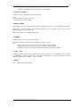
Section 1: FLIGHT MANAGEMENT, NAVIGATION CONTROLS AND INDICATORS
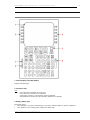
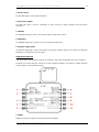
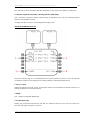
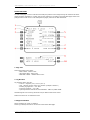
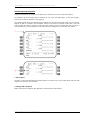
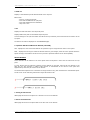
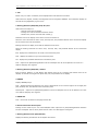
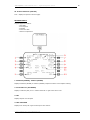
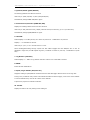
FLIGHT MANAGEMENT SYSTEM CONTROL DISPLAY UNIT (CDU)
1. Control Display Unit (CDU) Display
Displays FMS data pages.
2. Line Select Keys
Push
−
−
−
−
moves data from scratchpad to selected line
moves data from selected line to scratchpad
selects page, procedure, or performance mode as applicable
deletes data from selected line when DELETE is displayed in scratchpad.
3. Display (DSPY) Light
Illuminated (white) •
when RTE page 3 or greater, RTE LEGS page 2 or greater, RTE DATA page 2 or greater is displayed
•
when airplane is not in holding pattern displayed on HOLD page
© 2011 Captain Sim www.captainsim.com
6
‘757 Captain’ FLIGHT MANUAL Part V – Flight Management System
DO NOT USE FOR FLIGHT
•
7
when modification is in progress, and any RTE, RTE LEGS, RTE DATA, HOLD, or VNAV page is displayed.
4. FAIL Light
Illuminated (amber) - fault detected in related FMC
5. Brightness Control
Rotate - controls display brightness.
6. Message (MSG) Light
Illuminated (white) - scratchpad message is displayed.
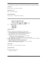
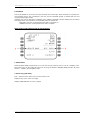
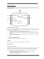
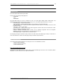
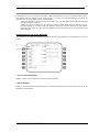
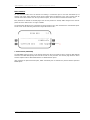
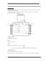
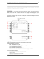
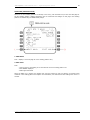
FUNCTION AND EXECUTE KEYS
1. CDU Function Keys
Push•
INIT REF - displays page for data initialization or for reference data
•
RTE - displays page to input or change origin, destination, or route
•
DEP ARR - displays page to input or change departure and arrival procedures
•
VNAV - displays page to view or change vertical navigation path data
•
FIX - displays page to create reference points on HSI map
•
LEGSdisplays page to evaluate or modify lateral and vertical route data
displays page to control HSI PLAN mode display
•
HOLD - displays page to create holding patterns and show holding pattern data
•
PROG - displays page to view dynamic flight and navigation data, including waypoint and destination
ETAs, fuel remaining, and arrival estimates
•
MENU - displays page to choose subsystems controlled by CDU
•
NAV RAD — displays page to monitor or control VOR tuning
•
PREV PAGE - displays previous page of related pages (for example, LEGS pages)
•
NEXT PAGE - displays next page of related pages.
2. Execute Light
Illuminated (white) - active data is modified but not executed.
3. Execute (EXEC) Key
Push•
makes data modifications) active
•
extinguishes execute light.
© 2011 Captain Sim www.captainsim.com
‘757 Captain’ FLIGHT MANUAL Part V – Flight Management System
DO NOT USE FOR FLIGHT
8
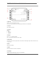
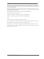
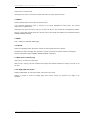
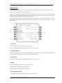
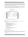
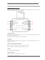
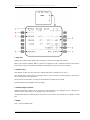
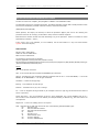
ALPHA/NUMERIC AND MISCELLANIOUS KEYS
1. Alpha/Numeric Keys
Push•
puts selected character in scratchpad
•
Slash (/) key - puts "/" in scratchpad
•
Plus Minus (+/-) key - first push puts "-" in scratchpad. Subsequent pushes alternate between "+" and
"-".
2. Clear (CLR) Key
Push•
clears last scratchpad character
•
clears scratchpad message.
Push and hold - clears all scratchpad data.
3. Delete (DEL) Key
Push - puts "DELETE" in scratchpad.
4. Space (SP) Key
Push - puts space in scratchpad
© 2011 Captain Sim www.captainsim.com
‘757 Captain’ FLIGHT MANUAL Part V – Flight Management System
DO NOT USE FOR FLIGHT
9
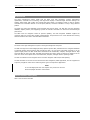
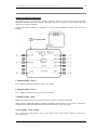
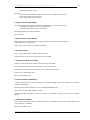
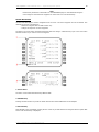
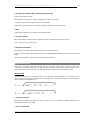
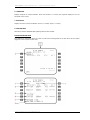
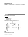
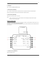
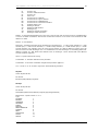
CDU PAGE COMPONENTS
1. Page Title
Subject or name of data displayed on page.
ACT (active) or MOD (modified) shows whether page contains active or modified data.
2. Line Title
Title of data on line below.
3. Line Data
Displays •
data
•
entry field
•
prompts
4. Prompts
Caret "<" or ">" indicates a prompt.
Push - selects indicated information, mode, or page.
5. Page Number
Left number is page number. Right number is total number of related pages. Page number is blank when only
one page exists.
6. Boxes
Data input is mandatory.
7. Dashes
Data input is optional. The data is not mandatory.
8. Scratchpad
Displays messages, alphanumeric entries or line selected data.
© 2011 Captain Sim www.captainsim.com
‘757 Captain’ FLIGHT MANUAL Part V – Flight Management System
DO NOT USE FOR FLIGHT
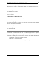
FMC ANNUNCIATOR LIGHT
1. FMC Annunciator Light
Illuminated (amber) •
CDU is displaying an operationally significant message in the scratchpad.
•
pushing CDU CLR key extinguishes the light and clears the scratchpad message.
© 2011 Captain Sim www.captainsim.com
10
‘757 Captain’ FLIGHT MANUAL Part V – Flight Management System
DO NOT USE FOR FLIGHT
11
Section 2: FLIGHT MANAGEMENT SYSTEM DESCRIPTION
INTRODUCTION
The flight management system (FMS) aids the flight crew with navigation, in-flight performance
optimization, automatic fuel monitoring, and flight deck displays. Automatic flight functions manage the
airplane lateral flight path (LNAV) and vertical flight path (VNAV). The displays include a map for airplane
orientation and command markers on the airspeed, altitude, and thrust indicators to help in flying efficient
profiles.
The flight crew enters the applicable route and flight data into the CDUs. The FMS then uses the navigation
database, airplane position, and supporting systems to calculate commands for manual and automatic flight
path control.
The FMS tunes the navigation radios for position updating. The FMS navigation database supplies the
necessary data to fly routes, SIDs, STARs, holding patterns, and procedure turns. Cruise altitudes and crossing
altitude restrictions are used to calculate VNAV commands.
FLIGHT MANAGEMENT COMPUTER (FMC)
The heart of the flight management system is the flight management computer.
The FMC uses flight crew-entered flight plan data, airplane systems data, and data from the navigation database
to calculate airplane present position and generate the pitch, roll, and thrust commands necessary to fly an
optimum flight profile. The FMC sends these commands to the autothrottle, autopilot, and flight director. Map
and route data are sent to the HSIs. The EFIS control panels are used to select the data to be displayed on the
HSIs. The mode control panel selects the autothrottle, autopilot, and flight director operating modes.
The FMC is certified for area navigation when used with navigation radio and/or GPS updating.
The FMC and CDU are used for enroute and terminal area navigation, RNAV approaches, and as a supplement
to primary navigation means when conducting other types of nonprecision approaches.
Note:
To use FSX flight plans with ‘757 Captain’ they need to be saved at
Documents/Flight Simulator X Files folder.
CONTROL DISPLAY UNITS (CDUS)
CDU is used to control the FMC.
© 2011 Captain Sim www.captainsim.com
‘757 Captain’ FLIGHT MANUAL Part V – Flight Management System
DO NOT USE FOR FLIGHT
12
Section 3: FLIGHT MANAGEMENT SYSTEM OPERATION
When first powered, the FMS is in the preflight phase.
As a phase is completed, the FMS changes to the next phase in this order:
•
•
•
•
•
•
•
preflight
takeoff
climb
cruise
descent
approach
flight complete
PREFLIGHT
During preflight, flight plan and load sheet data are manually entered into the CDU. The flight plan defines
the route of flight from the origin to the destination and initializes LNAV. Flight plan and load sheet data
provide performance data to initialize VNAV.
Required preflight data consists of:
• initial position
• route of flight
• performance data
• takeoff data
Optional preflight data includes:
• navigation database selection
• route 2
• SID
• STAR
Each required or optional data item is entered on specific preflight pages.
Preflight starts with the IDENT page. If the IDENT page is not displayed, it can be selected with the IDENT
prompt on the INIT/REF INDEX page. Visual prompts help the flight crew select necessary CDU preflight
pages. Preflight pages can be manually selected in any order.
After the necessary data on each preflight page is entered and checked, push the lower right line select key
to select the next preflight page. When ACTIVATE is selected on the ROUTE page, the execute (EXEC) light
illuminates. Push the EXEC key to make the route active.
Use the departure/arrival (DEP/ARR) page to select a standard instrument departure (SID). Selection of the
SID may cause a route discontinuity in the flight plan. The modification must be connected to the existing
route and executed. This can be accomplished on the ROUTE or LEGS page.
When all required preflight entries are complete, PRE-FLT COMPLETE is displayed on the TAKEOFF REF page.
TAKEOFF
The takeoff phase starts with engagement of takeoff trust on the MCP and extends to the thrust reduction
altitude where climb thrust is normally selected.
CLIMB
The climb phase starts at the thrust reduction altitude and extends to the top of climb (T/C) point. The T/C is
the position where the airplane reaches the cruise altitude entered on the PERF INIT page.
CRUISE
The cruise phase starts at the T/C point and extends to the top of descent (T/D) point. Cruise can include
step climbs and en route descents.
© 2011 Captain Sim www.captainsim.com
‘757 Captain’ FLIGHT MANUAL Part V – Flight Management System
DO NOT USE FOR FLIGHT
13
DESCENT
The descent phase starts at the T/D point or when the VNAV descent page becomes active. The descent
phase extends to the start of the approach phase.
APPROACH
The approach phase starts when intercepting the first leg of a published approach selected from the
ARRIVALS page.
OPERATIONAL NOTES
When operating in the LNAV and VNAV modes, system operation must be monitored for unwanted pitch, roll,
or thrust commands. If unwanted operation is noticed, roll and pitch modes other than LNAV and VNAV must
be selected.
The system must be carefully monitored for errors following:
• activation of a new data base
• power interruption
• IRS failure.
When operating far off the route, the FMC may not sequence the active waypoint when the airplane passes
abeam the waypoint.
LNAV can only capture the active leg. It cannot capture an inactive leg in the active route. The DIRECT TO
procedures can be used to create an active leg for capture.
When a waypoint is in the route more than once, certain route modifications (such as DIRECT TO and HOLD)
use the first waypoint in the route.
When entering airways in a route page, the start and end waypoints must be in the data base. Otherwise,
the route segment must be entered as a DIRECT leg.
TERMINOLOGY
The following paragraphs describe FMC and CDU terminology.
Active - flight plan data being used to calculate LNAV or VNAV guidance commands.
Activate - the procedure to change an inactive route to the active route for navigation. It is a two step
procedure.
• select the ACTIVATE prompt
• push the execute (EXEC) key.
Altitude constraint - a crossing restriction at a waypoint.
Delete - using the delete (DEL) key to remove FMC data and revert to default values, dash or box prompts,
or a blank entry.
Econ - a speed schedule calculated to minimize operating cost. The economy speed is based on the cost
index. A low cost index causes a lower cruise speed. Maximum range cruise or the minimum fuel speed
schedule may be obtained by entering a cost index of zero. This speed schedule ignores the cost of time.
A low cost index may be used when fuel costs are high compared to operating costs.
A minimum time speed schedule may be obtained by entering a cost index of 9999. This speed schedule
calls for maximum flight envelope speeds.
Enter - put data in the CDU scratchpad and line select the data to the applicable location. New characters
can be typed or existing data can be line selected to the scratchpad for entry.
Erase - remove entered data, which has resulted in a modification, by selecting the ERASE prompt.
© 2011 Captain Sim www.captainsim.com
‘757 Captain’ FLIGHT MANUAL Part V – Flight Management System
DO NOT USE FOR FLIGHT
14
Execute - push the illuminated EXEC key to make modified data active. Inactive - data not being used to
calculate LNAV or VNAV commands. Initialize - entering data required to make the system operational.
Message - FMC information displayed in the scratchpad.
Modify - to change active data. When a modification is made to the active route or performance mode, MOD
displays in the page title, ERASE displays next to line select key 6 left, and the EXEC key illuminates.
Prompt — CDU symbol that aids the flight crew in accomplishing a task. Prompts can be boxes, dashes, or
symbols (< or >) to remind the flight crew to enter or select data.
Select - pushing a key to obtain the necessary data or action, or to copy selected data to the scratchpad.
Speed restriction - an airspeed limit associated with a specified altitude entered by the flight crew.
Speed transition - an airspeed limit associated with a specified altitude entered by the FMC.
Waypoint - a point on the route or in the navigation database. It can be a fixed point such as a latitude and
longitude, VOR or ADF station, or an airway intersection. A conditional waypoint is not associated with a land
reference; it is based on a time or altitude requirement. An example of a conditional waypoint is "when
reaching 1000 feet".
LATERAL NAVIGATION (LNAV)
LNAV provides steering commands to the next waypoint or the selected route intercept point. When selected
after takeoff, LNAV engages when laterally within 2.5 nautical miles of the active route leg. FMC LNAV
guidance normally provides great circle courses between waypoints. However, when an arrival or approach
from the FMC data base is entered into the active route, the FMC commands a heading, track, to comply
with the procedure.
WAYPOINTS
Waypoint (navigation fix) identifiers display on the CDU and HSI.
The CDU message NOT IN DATABASE is displayed if a manually entered waypoint identifier is not in the data
base. The waypoint can still be entered as a latitude/longitude, place-bearing/distance or a placebearing/place-bearing waypoint.
FMC-generated waypoints contain a maximum of five characters assigned according to the following rules.
NAVAID WAYPOINTS
VHF - waypoints located at VHF navaids (VOR/DME/LOC) are identified by one, two, three or four character
facility identifier. Examples:
• Los Angeles VORTAC- LAX
• TyndallTACAN-PAM
• Riga Engure, Latvia - AN.
NDB - waypoints located at NDBs are identified by use of the station identifier. Example: FORT NELSON, CAN
- YE.
FIX WAYPOINTS
Waypoints located at fixes with names containing five or fewer characters are identified by the name.
Examples:
• DOT
• ACRA
• ALPHA.
© 2011 Captain Sim www.captainsim.com
‘757 Captain’ FLIGHT MANUAL Part V – Flight Management System
DO NOT USE FOR FLIGHT
15
LONG WAYPOINT NAMES
Waypoints with more than five characters are abbreviated using the following rules sequentially until five
characters remain. For double letters, one letter is deleted. Example:
• KIMMEL becomes KIMEL
Keep the first letter, first vowel and last letter. Delete other vowels starting from right to left. Example:
• BAILEY becomes BAILY
The next rule abbreviates names even further. Apply the previous rule, then delete consonants from right to
left. Example:
• BRIDGEPORT becomes BRIDGPRT then BRIDT
Fixes with multiword names use the first letter of the first word and abbreviate the last word, using the
above rules sequentially until a total of five characters remain. Examples:
• CLEAR LAKE becomes CLAKE
• ROUGH ROAD becomes RROAD.
UNNAMED WAYPOINTS
If an unnamed turn point, intersection, or fix is collocated with a named waypoint or navaid on a different
route structure (such as low altitude routes or an approach), the name or identifier of the collocated
waypoint is used. Example:
• Unnamed turn point on J2 between the Lake Charles (LCH) and New Orleans (MSY) VORTACs is
coincidental with the Lafayette (LFT) low altitude VORTAC. LFT is used as the identifier for the turn point.
Identifier codes for unnamed turn points not coincidental with named waypoints are constructed from the
identifier of a navaid serving the point and the distance from the navaid to the point. If the distance is 99
nautical miles or less, the navaid identifier is placed first, followed by the distance. If the distance is 100
nautical miles or more, the last two digits are used and placed ahead of the navaid identifier. Examples
(NAVAID - DISTANCE - IDENT):
• INW-18-INW18
• CSN-106-06CSN
Waypoint located at unnamed flight information region (FIR), upper flight information region (UIR), and
controlled airspace reporting points are identified by the three-letter airspace type identification followed by
a two-digit sequence number. Example:
• FRA01
Unnamed oceanic control area reporting points in the northern hemisphere use the letters N and E, while
points in the southern hemisphere use the letters S and W. Latitude always precedes longitude. For
longitude, only the last two digits of the three digit value are used.
Placement of the designator in the five character set indicates whether the first longitude digit is 0 or 1. The
letter is the last character if the longitude is less than 100° and is the third character if the longitude is 100°
or greater.
N is used for north latitude, west longitude. E is used for north latitude, east longitude. S is used for south
latitude, east longitude. W is used for south latitude, west longitude. Examples:
•
•
•
•
N50° W040° becomes 5040N
N75°W170° becomes 75N70
N50° E020° becomes 5020E
N06° El 10° becomes 06E10
•
•
•
•
S52°
S07°
S50°
S06°
W075° becomes 5275W
W120° becomes 07W20
E020° becomes 5020S
El 10° becomes 06S10.
PROCEDURE ARC FIX WAYPOINT NAMES
Unnamed terminal area fixes along a DME arc procedure are identified with the first character D. Characters
2 through 4 indicate the radial on which the fix lies. The last character indicates the arc radius. The radius is
expressed by a letter of the alphabet where A = 1 mile, B = 2 miles, C = 3 miles and so forth. Example:
•
EPH252°/24 = D252X
An unnamed waypoint along a DME arc with a radius greater than 26 miles is identified by the station
identifier and the DME radius. Example:
•
CPR338°/29 = CPR29
© 2011 Captain Sim www.captainsim.com
‘757 Captain’ FLIGHT MANUAL Part V – Flight Management System
DO NOT USE FOR FLIGHT
16
When there are multiple unnamed waypoints along a DME arc with a radius greater than 26 miles, the
station identifier is reduced to two characters, followed by the radius, and then a sequence character.
Examples:
• CPR134°/29 = CP29A
• CPR1900 /29 = CP29B
PROCEDURE FIX WAYPOINTS
Waypoints located at unnamed runway-related fixes are identified by adding a two-letter prefix to the
runway number.
Examples: CF04, RW18L.
Unnamed turn points that are part of a procedure are identified as a latitude and longitude waypoint. These
include waypoints (except conditional waypoints) defined by flying a course or track from a waypoint (except
conditional waypoints) to a radial or DME distance. These waypoints are automatically entered in a route by
selection of a procedure using these waypoints, from the departures or arrivals page.
Airport reference points are identified by the ICAO identifier.
DUPLICATE WAYPOINTS
Application of the abbreviation rules may create identical identifiers for different waypoints. When a duplicate
waypoint identifier is entered, the page changes to the SELECT DESIRED WPT page. The page lists the
latitude, longitude, and the type of facility or waypoint of all the waypoints with the same identifier. Select
the latitude/longitude of the correct waypoint to enter the correct waypoint on the original page.
© 2011 Captain Sim www.captainsim.com
‘757 Captain’ FLIGHT MANUAL Part V – Flight Management System
DO NOT USE FOR FLIGHT
17
CONDITIONAL WAYPOINTS
Conditional waypoints may be displayed in the route when selecting a DEPARTURES or ARRIVALS page
procedure. Usually, conditional waypoints cannot be manually entered on a route or legs page. These
waypoints indicate when an event occurs and are not at a geographically-fixed position. The types of
conditions are:
• climb/descent through an altitude
• flying a heading to a radial or DME distance
• intercepting a course
• heading vectors to a course or fix.
Altitude and course intercept conditional waypoints display on the CDU inside (parenthesis) marks. The
diagram below shows conditional waypoints.
MANUALLY ENTERED LATITUDE/ LONGITUDE WAYPOINTS
Pilot defined waypoints entered as a latitude and longitude are shown in a seven-character format. Latitude
and longitude waypoints are entered with no space or slash between the latitude and longitude entries.
Leading zeroes must be entered. All digits and decimal points (to 1/10 minute) must be entered unless the
latitude or longitude are full degrees. Examples:
• N47° W008° is entered as N47W008 and displays as N47W008
• N47° 15.4' W008° 3.4' is entered as N4715.4W00803.4 and displays as N47W008.
MANUALLY ENTERED PLACE-BEARING/DISTANCE OR PLACE-BEARING/PLACE-BEARING
WAYPOINTS
Waypoints entered as a place-bearing/distance or place-bearing/place-bearing are identified by the first
three characters of the entry followed by a two-digit sequence number. Examples:
• SEA330/10 becomes SEA01
• SEA330/OLM020 becomes SEA02.
The two digit sequence numbers reserved for RTE1 are 01 through 49. The two digit sequence numbers
reserved for RTE2 are 51 through 99.
MANUALLY ENTERED AIRWAY CROSSING WAYPOINTS
Airway crossing fixes are entered as a five character waypoint name or by entering consecutive airways on
the ROUTE page. In the latter case, the display is an X followed by the second airway name. Example:
© 2011 Captain Sim www.captainsim.com
‘757 Captain’ FLIGHT MANUAL Part V – Flight Management System
DO NOT USE FOR FLIGHT
18
entering J70 on the VIA line of the ROUTE page causes box prompts to display opposite on the same line.
Leaving the box prompts empty and entering J52 on the next VIA line, directly below J70, causes the FMC to
calculate the intersection of the two airways and replace the boxes with the waypoint identifier, XJ52.
MANUALLY ENTERED ALONG-TRACK WAYPOINTS
Along-track waypoints are created on the active route and do not cause route discontinuities when they are
created.
Along-track waypoints are entered using the waypoint name (the place), followed by a slash and minus sign,
for points before the waypoint, or no sign for points after the waypoint, followed by the mileage offset for
the newly defined waypoint. The distance offset must be less than the distance between the originating
waypoint and next (positive value) or preceding (negative value) waypoint. Latitude and longitude waypoints
cannot be used to create along-track waypoints. Examples:
• VAMPS/25 is 25 miles after VAMPS on the present route and displays as VAM01
• ELN/-30 is 30 miles before ELN on the present route and displays as ELN01.
HSI MAP DISPLAYS
The route is displayed on the HSI in MAP, and PLAN modes. The display color and format represent the
following status:
•
•
•
•
•
an inactive route is displayed as a cyan dashed line
an activated, but not yet executed route, is displayed as a white dashed line
the active route is displayed in magenta
modifications to an active route are shown as dashed white lines
modified waypoints are displayed in white
The HSI displays the FMC position at the apex of the airplane symbol. All HSI map data displays relative to
this apex.
VERTICAL NAVIGATION (VNAV)
VNAV provides vertical profile guidance through the climb, cruise, and descent phases of flight.
SPEED/ALTITUDE CONSTRAINTS
VNAV controls the path and speed to comply with waypoint crossing constraints. Waypoint crossing
constraints are entered on the LEGS page waypoint line by pushing the applicable key on the right side of
the CDU. Values entered as part of a procedure and manually entered constraints are shown in large font.
FMC predicted values do not act as constraints, and are displayed in small font.
Waypoints can have altitude or airspeed/altitude constraints. Speed constraint entries require an altitude
constraint at the same waypoint. All speed constraints are considered by the FMC as at or below constraints.
At or above altitude constraints are entered with a suffix letter A (example: 220A). At or below altitude
constraints are entered with a suffix letter B (example: 240B). Mandatory altitude constraints are entered
without any suffix letter (example: 270).
Altitude constraints with two altitudes may be entered in either order. The lower altitude constraint, followed
by a suffix letter A, and the upper altitude constraint, followed by a suffix letter B (example: 220A240B or
240B220A).
© 2011 Captain Sim www.captainsim.com
‘757 Captain’ FLIGHT MANUAL Part V – Flight Management System
DO NOT USE FOR FLIGHT
19
TAKEOFF AND CLIMB
1. Takeoff
The takeoff (TO) pitch mode is used for the takeoff and initial climb. VNAV is normally engaged at 1000 feet
and pitch guidance continues to maintain the target airspeed.
During takeoff the target airspeed is between V2 + 15 and V2 + 25 knots. When VNAV is engaged the FMC
airspeed is set to the target airspeed.
When VNAV is engaged (above 400 feet) the thrust reference changes to climb.
© 2011 Captain Sim www.captainsim.com
‘757 Captain’ FLIGHT MANUAL Part V – Flight Management System
DO NOT USE FOR FLIGHT
20
2. Acceleration Height
At the acceleration height, flap retraction, or AFDS altitude capture before acceleration height, VNAV
commands an airspeed increase to 250 knots or the speed transition associated with the origin airport,
limited by configuration
3. VNAV Climb
The VNAV climb profile uses VNAV SPD or VNAV PTH at the default climb speed or pilot selected climb speed
to remain within all airspeed and altitude constraints that are part of the SID entered into the active route.
Autothrottle uses selected climb thrust limit.
4. Climb Constraints
VNAV enters the VNAV PTH mode to remain within departure or waypoint constraints. Speed maintained
during this time can be:
• procedure based speed restriction
• waypoint speed restriction
• default VNAV climb speed
• manually entered climb speed.
5. Top of Climb (T/C)
The point where the climb phase meets the cruise altitude is called the top of climb. Approaching this point,
the FMC changes from the climb phase to the cruise phase. The T/C point is displayed on the map as a green
circle with the label T/C.
CRUISE
At cruise altitude, the FMC commands economy cruise speed or the pilot entered speed until reaching the
top-of-descent (T/D) point. Alternate cruise speed is flight crew entered speed.
If the cost index is set to zero the FMC commands maximum range cruise speed. Cost index modifications
are allowed until within ten miles of the top of descent.
CRUISE CLIMB
When VNAV is engaged, resetting the MCP to an altitude higher than the current cruise altitude causes the
new altitude to be displayed in the scratchpad of the CDU. The altitude can then be entered on the CRZ ALT
line on the cruise page. When the modification is executed the airplane will climb to the new cruise altitude.
The CRZ page displays ACT ECON CRZ CLB.
STEP CLIMB
Fuel and ETA predictions assume the airplane climbs at each predicted step climb point as airplane weight
decreases. FMC predicted step climb increments are based on the step size entered on the CRZ page.
Entering a step size of zero causes the FMC to assume a constant altitude cruise. Flight crew entry of a step
altitude on the CRZ page overrides the FMC step climb predictions.
Predicted step altitudes are displayed on the RTE LEGS page. The distance and ETA to the next step point is
displayed on the CRZ and progress pages. Step points are displayed on the HSI map with a green circle and
S/C label.
CRUISE DESCENT
The new cruise altitude can be entered on the cruise page. When the modification is executed the CRZ page
displays ACT ECON CRZ DES.
© 2011 Captain Sim www.captainsim.com
‘757 Captain’ FLIGHT MANUAL Part V – Flight Management System
DO NOT USE FOR FLIGHT
21
Note
A cruise descent will not provide speed adjustments to comply with speed restrictions
or transition altitude speeds. Transition or speed restrictions must be maintained by
flight crew action.
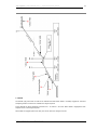
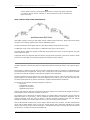
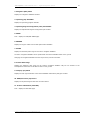
MODE CONTROL PANEL SPEED INTERVENTION
With VNAV engaged, pushing the IAS MACH selector enables speed intervention. Speed intervention allows
the flight crew to change airplane speed with the IAS/MACH selector.
The above illustration shows VNAV mode for each phase of flight during speed intervention.
In VNAV PTH mode, thrust controls speed; in VNAV SPD mode, pitch controls speed.
In a path descent, VNAV PTH changes to VNAV SPD during speed intervention. In all other phases, the pitch
mode remains the same.
In approach phase (see Approach topic this section), during speed intervention, pitch mode remains in VNAV
PTH and the vertical path is maintained regardless of IAS MACH selector changes.
DESCENT
The FMC calculates a descent path based on airspeed and altitude constraints and the end of descent (E/D)
point.
An E/D point is created by the FMC when an arrival or approach procedure is selected on the ARRIVALS page
and incorporated into the flight plan. During cruise, an E/D point is also created when an altitude constraint
less than cruise altitude is added to a downstream waypoint on the LEGS page.
The FMC calculates the top of descent (T/D) point after the E/D is entered. T/D is the point where the cruise
phase changes to the descent phase. The T/D is displayed on the HSI as a green circle with the label T/D.
The descent path starts at the T/D and includes any waypoint altitude/airspeed constraints.
The path to the first altitude constrained waypoint is based on:
• idle thrust
• speedbrakes retracted
• predicted use of anti-ice
• applicable target speed
Descent path segments after the first altitude constrained waypoint are constructed as straight line point-topoint segments from one altitude constraint to the next.
The airspeed used to determine the descent path is the existing VNAV cruise airspeed, normally economy
Mach/CAS (based on Cost Index), and any additional descent airspeed constraints. Waypoints with an
airspeed constraint must also have an altitude constraint. Airspeed constraints after the first altitude
constrained waypoint are treated as speed limits (e.g. at or below the speed constraint)
With the MCP altitude set below the current airplane altitude and at the T/D point, the FMC commands idle
thrust and the AFDS pitches down to track the vertical descent path. AFDS pitch maintains the vertical
descent path while the angle of the descent path is calculated by the FMC to maintain the descent airspeed
(at idle thrust), normally economy descent Mach/CAS.
© 2011 Captain Sim www.captainsim.com
‘757 Captain’ FLIGHT MANUAL Part V – Flight Management System
DO NOT USE FOR FLIGHT
22
If the airplane passes the T/D point and the window altitude has not been set lower, or if the airplane levels
at an MCP altitude not in the FMC descent profile, ALT HOLD annunciates. To reinitiate/continue the descent,
the MCP altitude must be reset and VNAV re-engaged.
When a speed transition altitude is included in the descent path (typically 250 kts below 10,000 ft), the
descent path angle shallows temporarily to slow to the transition altitude airspeed. Below the speed
transition altitude, the descent path angle increases to maintain a target speed 10 kts below the transition
speed (typically 240 kts) to allow for unforcast tailwinds.
Final deceleration is commanded to arrive at the final approach fix or the outer marker at 170 kts. It is the
flight crew's responsibility to extend flaps as appropriate when the final deceleration segment to 170 kts is
initiated by VNAV.
Note
Adding, deleting or revising altitude constraints after VNAV enters the descent mode causes
a recalculation of the descent path by the FMC. This may cause VNAV to revert to speed
reversion mode (VNAV SPD) if the newly calculated path is above or below the old path far
enough so as to prevent the path from remaining captured.
EARLY DESCENT
An early descent is initiated by forcing the FMC into the descent phase before reaching the top of descent
point. VNAV commands a descent at a reduced descent rate until the idle descent path is intercepted.
1. DES NOW
Use the DES NOW prompt on the DES page. VNAV starts an early descent and captures the idle descent
path.
2. Within 50 NM of Top of Descent Point
Use the MCP altitude selector to start an early descent. Within 50 NM of the top of descent point, VNAV
starts an early descent and captures the idle descent path.
3. More than 50 NM from Top of Descent Point
Enter a new cruise altitude to start a cruise descent. If the distance from the top of descent is more than 50
NM, VNAV begins a cruise descent to the new cruise altitude and the new T/D is displayed.
© 2011 Captain Sim www.captainsim.com
‘757 Captain’ FLIGHT MANUAL Part V – Flight Management System
DO NOT USE FOR FLIGHT
Monitor the descent profile to ensure the new cruise altitude is reached before T/D.
© 2011 Captain Sim www.captainsim.com
23
‘757 Captain’ FLIGHT MANUAL Part V – Flight Management System
DO NOT USE FOR FLIGHT
24
APPROACH
VNAV will fly the computed descent path to the E/D point altitude if the MCP altitude is set at or below the
E/D point altitude. However, it is the responsibility of the flight crew not to descend below the MDA of the
approach being flown until adequate visual contact is achieved.
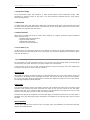
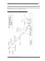
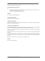
CRUISE AND DESCENT PROFILE (NONPRECISION APPROACH)
© 2011 Captain Sim www.captainsim.com
‘757 Captain’ FLIGHT MANUAL Part V – Flight Management System
DO NOT USE FOR FLIGHT
25
1. Cruise
Before the top of descent, FMC is in cruise mode and uses VNAV PTH and ECON cruise speed.
2. Level Descent Phase
After top of descent, FMC is in descent mode, VNAV decreases airspeed to ECON descent speed, maintains
altitude in VNAV PTH.
3. Descent
Upon reaching descent speed, VNAV descends in VNAV PTH at ECON descent speed.
4. Speed Limit Protection
If a tailwind causes the airplane to accelerate the DRAG REQUIRED scratchpad message will be displayed. If
the speedbrakes are not deployed, the pitch mode will change to VNAV SPD and depart the path before the
speed reaches the limit.
5. Speed Restriction Deceleration
Before the speed restriction altitude, VNAV decelerates to commanded speed using VNAV PTH.
6. Descent and Approach
When at restricted speed, VNAV descends and starts approach in VNAV PTH at commanded speed.
7. Minimum Descent Altitude
When the MDA is reached with VNAV engaged the airplane will maintain the MDA altitude in VNAV PTH.
If the missed approach point is crossed without selecting GA, VNAV will maintain the missed approach point
altitude until GA is selected.
8. Go-Around (GA)
The missed approach go-around is commenced by pushing a Go-Around switch. Pushing a Go-Around switch
sets go-around thrust.
© 2011 Captain Sim www.captainsim.com
‘757 Captain’ FLIGHT MANUAL Part V – Flight Management System
DO NOT USE FOR FLIGHT
26
DATA ENTRY RULES
ALTITUDE ENTRY
Altitudes can be entered into the FMC as three digit (XXX), four digit (XXXX), five digit (XXXXX), or flight
level (FLXXX) numbers. The FMC displays altitude or flight level entries in the proper form based on the
transition altitude. Some data lines further restrict the valid entry forms.
Three digit entries represent altitude or flight levels in increments of 100 feet. Leading zeros are required.
Examples of three digit (XXX, FLXXX) entries with transition altitude = 10,000 feet:
• 800 feet is entered as 008 or FL008; displays as 800
• 1,500 feet is entered as 015 or FL015; displays as 1500
• 11,500 feet is entered as 115 or FL115; displays as FL115
• 25,000 feet is entered as 250 or FL250; displays as FL250.
Four digit entries represent feet, rounded to the nearest ten feet. Leading zeros are required. This form is
used when the altitude does not exceed 9,994 feet.
Examples of four digit (XXXX) entries with transition altitude = 18,000 feet:
• 50 feet is entered as 0050; displays as 50
• 835 feet is entered as 0835; displays as 840
• 1,500 feet is entered as 1500; displays as 1500
• 8,500 feet is entered as 8500; displays as 8500
• 9,994 feet is entered as 9994; displays as 9990.
Five digit entries represent feet, rounded to the nearest ten feet. This form is used when the altitude
exceeds 9,994 feet
Examples of five (XXXXX) digit entries with transition altitude = 4,000 feet:
• 50 feet is entered as 00050; displays as 50
• 835 feet is entered as 00835; displays as 840
• 1,500 feet is entered as 01500; displays as 1500
• 8,500 feet is entered as 08500; displays as FL085
• 9,995 feet is entered as 09995; displays as FL100
• 11,500 feet is entered as 11500; displays as FL115
• 25,000 feet is entered as 25000; displays as FL250.
Negative altitude entries are allowed to -1000 feet.
AIRSPEED ENTRY
Airspeeds can be entered into the FMC as calibrated airspeed (CAS) or Mach number (M). CAS is entered as
three digits (XXX) in knots. Mach numbers are entered as one, two, or three digits following a decimal point.
DATA PAIRS
Many CDU pages display data in pairs separated by a slash "/." Examples of these pairs include wind
direction/speed and waypoint airspeed/altitude constraints. When entering both values in a pair, the slash is
inserted between the values. When it is possible to enter only one value of the pair, the slash may not be
required. When entering only the outboard value of a pair, the trailing or leading slash may be entered, but
is not required before transferring to the data line. When entering the inboard value of a pair, the trailing or
leading slash must be entered before transferring to the data line. Omission of the required slash normally
results in an INVALID ENTRY message.
© 2011 Captain Sim www.captainsim.com
‘757 Captain’ FLIGHT MANUAL Part V – Flight Management System
DO NOT USE FOR FLIGHT
27
Section 4: FLIGHT MANAGEMENT COMPUTER
FMC DATABASES
The FMC contains two databases:
• performance database
• navigation database
The performance database supplies all the necessary performance data to the flight crew. It supplies the
FMC with the necessary data to calculate pitch and thrust commands. All necessary data can be shown on
the CDU. The database includes:
• airplane drag and engine characteristics
• maximum and optimum altitudes
• maximum and minimum speeds.
The navigation database includes most data usually found on navigation charts. This data can be shown on
the CDU or HSI. The database contains:
• the location of VHF navigation aids
• airports
• runways
• other airline selected data, such as SIDs, STARs, approaches, and company routes
• transition altitudes.
THRUST MANAGEMENT
The autothrottle is controlled by the thrust management computer. When VNAV is engaged, the FMC
controls the autothrottle by setting the command speeds and thrust reference modes on the thrust
management computer.
When VNAV is not engaged, the thrust management is controlled by the flight crew as part of the AFDS
system.
ОВЕРКА FMC НАЧИНАЕТСЯ ОТСЮДА
© 2011 Captain Sim www.captainsim.com
‘757 Captain’ FLIGHT MANUAL Part V – Flight Management System
DO NOT USE FOR FLIGHT
28
Section 5: FMC PREFLIGHT
INTRODUCTION
FMC preflight is required before flight.
Completion of the FMC preflight requires data entry in all minimum required data locations. Additional entry
of optional preflight data optimizes FMC accuracy.
PREFLIGHT PAGE SEQUENCE
The usual FMC power-up page is the identification page. Preflight flow continues in this sequence:
• identification (IDENT) page
• position initialization (POS INIT) page
• ROUTE page
• DEPARTURES page (no automatic prompt)
• performance initialization (PERF INIT) page
• takeoff reference (TAKEOFF REF) page.
Some of these pages are also used in flight.
MINIMUM PREFLIGHT SEQUENCE
During preflight, a prompt in the lower right directs the flight crew through the minimum requirements for
preflight completion. Selecting the prompt key displays the next page in the flow. If a required entry is
missed, a prompt on the TAKEOFF page leads the flight crew to the preflight page missing data.
Airplane inertial position is necessary for FMC preflight and flight instrument operation.
A route must be entered and activated. The minimum route data is origin and destination airports, and a
route leg.
© 2011 Captain Sim www.captainsim.com
‘757 Captain’ FLIGHT MANUAL Part V – Flight Management System
DO NOT USE FOR FLIGHT
29
Performance data requires the airplane weight and cruise altitude.
Takeoff data requires a flap setting.
SUPPLEMENTARY PAGES
Supplementary pages are sometimes required, these pages have no prompts and interrupt the usual
sequence. Discussions of each page includes methods to display the page.
When the route includes SIDs and STARs, they can be entered using the DEPARTURES or ARRIVALS pages.
Route discontinuities are removed and the route is modified on the ROUTE and RTE LEGS pages.
Speed/altitude restrictions are entered and removed on the RTE LEGS page. The RTE LEGS page is described
in the FMC Cruise section.
Waypoint, navaid, airport, and runway data is referenced on the REF NAV DATA page. The REF NAV DATA
page is described in the FMC Cruise section.
PREFLIGHT PAGES - PART 1
The preflight pages are presented in the sequence used during a typical preflight.
INITIALIZATION/REFERENCE INDEX PAGE
The initialization/reference index page allows manual selection of several FMC pages. It gives access to most
of the pages used during preflight.
1. Identification (IDENT)
The IDENT page is the first page in the preflight sequence.
© 2011 Captain Sim www.captainsim.com
‘757 Captain’ FLIGHT MANUAL Part V – Flight Management System
DO NOT USE FOR FLIGHT
30
2. Position (POS)
The POS INIT page is used for IRS initialization.
3. Performance (PERF)
The PERF INIT page is used for initialization of data required for VNAV operations and performance
predictions.
4. TAKEOFF
The TAKEOFF REF page is used to enter takeoff reference data and V speeds.
5. APPROACH
The APPROACH REF page is used for entry of the approach VREF speed.
6. Navigation (NAV) DATA
The REF NAV DATA page is used to access data on waypoints, navaids, airports, and runways. The REF NAV
DATA page is accessible only from this page.
IDENTIFICATION PAGE
Most of the data on this page is for flight crew verification. Active date and drag/fuel flow can be modified.
The flight crew verifies FMC data, selects the current navigation database, and checks or modifies drag and
fuel flow factors on the identification page.
1. MODEL
Displays the airplane model from the FMC performance database.
© 2011 Captain Sim www.captainsim.com
‘757 Captain’ FLIGHT MANUAL Part V – Flight Management System
DO NOT USE FOR FLIGHT
31
2. Navigation (NAV) DATA
Displays the navigation database identifier.
3. Operating (OP) PROGRAM
Displays the operating program identifier.
4. Operating Program Configuration (OPC) Part Number
Displays the Operational Program Configuration part number.
5. INDEX
Push - displays the INIT/REF INDEX page.
6. ENGINES
Displays the engine model from the FMC performance database.
7. ACTIVE
Displays the effectivity date range for the active navigation database.
The active navigation database can be replaced with the inactive database while on the ground.
Changing the navigation database removes all previously entered route data.
8. Inactive Date Range
Displays the effectivity date range for the inactive navigation database. May be line selected to the
scratchpad and inserted to the ACTVE line while on the ground.
9. Company (CO) DATA
Displays the last eight characters of the Airline Modifiable Information (AMI) part number.
10. DRAG/Fuel Flow (FT) Factors
Displays the airplane drag and fuel flow correction factors.
11. Position Initialization (POS INIT)
Push - displays the POS INIT page.
© 2011 Captain Sim www.captainsim.com
‘757 Captain’ FLIGHT MANUAL Part V – Flight Management System
DO NOT USE FOR FLIGHT
32
POSITION INITIALIZATION PAGE
The position initialization page allows entry of airplane present position for IRS alignment. This page is also
used to enter the heading when an IRS is in the ATT mode.
1. Reference Airport (REF AIRPORT)
Entry of the reference airport displays the airport latitude/longitude.
Optional entry.
Valid entries are ICAO four letter airport identifiers.
Removes previous GATE entry.
Entry blanks when airborne.
2. GATE
The gate entry allows further refinement of the latitude/longitude position.
© 2011 Captain Sim www.captainsim.com
‘757 Captain’ FLIGHT MANUAL Part V – Flight Management System
DO NOT USE FOR FLIGHT
33
Optional entry after reference airport entered.
3. Coordinated Universal Time (UTC)
UTC -
• displays time from captain's clock when operative; otherwise, displays time from first officer's clock
• hours set by entering desired hour reference
• minutes set by resetting appropriate pilot's clock.
4. INDEX
Push - displays the INIT/REF INDEX page.
5. Last Position (LAST POS)
Displays the last FMC calculated position.
6. GPS Position (GPS POS)
Displays the GPS present position. During preflight, the GPS POS may not display due to satellite availability,
performance, or unfavorable geometry.
7. Set IRS Position (SET IRS POS)
The set inertial position entry is required to initialize the IRS. Select the most accurate latitude/longitude
from LAST POS, REF AIRPORT, GATE, GPS POS, or a manual entry to initialize the IRS.
If an entry is not made before the IRS completes the initial alignment, the scratchpad message ENTER IRS
POSITION is displayed.
If the manually entered position fails the IRS internal check, the scratchpad message ENTER IRS POSITION
is displayed.
The manually entered position is also compared with the FMC origin airport position. If the entered position
is not within 6 NM of the FMC origin airport position, the scratchpad message IRS POS/ORIGIN DISAGREE is
displayed.
Blanks when the IRS changes from the alignment to the navigation mode.
8. ROUTE
Push - displays the ROUTE page.
© 2011 Captain Sim www.captainsim.com
‘757 Captain’ FLIGHT MANUAL Part V – Flight Management System
DO NOT USE FOR FLIGHT
34
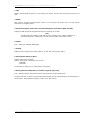
POSITION REFERENCE PAGES
POSITION REFERENCE PAGE 2/4
Position reference page 2 simulates displays positions calculated by the FMC, IRS, GPS, and radio navigation
receivers. The FMC position can be updated to IRS, GPS, or radio position on this page.
Positions are displayed as the latitude/longitude calculated by the individual systems. When BRG/DIST is
selected the IRS, GPS, and radio positions are shown as bearing and distance from the FMC position.
1. FMC Position and Source
The source used by the active FMC for position data is displayed next to the FMC line title. In the example,
the FMC uses LGPS for position data.
Displays the FMC calculated latitude/longitude.
Identifies the source for calculating the FMC position:
• GPS - position calculated from GPS and inertial position data
• IRS - position calculated from inertial position data only
• RADIO — position calculated from navigation radio and inertial position data
• LOC-GPS - position is calculated from localizer, GPS and inertial data
• LOC-RADIO - position is calculated from localizer, navigation radio and inertial data
• LOC - position is calculated from localizer and inertial data.
2. IRS
Displays latitude/longitude position or the bearing and distance from the FMC position determined by the
IRS. If the displayed position is derived from all three IRSs, (3) is displayed. If the position is from a single
IRS then (L), (C), or (R) is displayed to indicate which IRS position is displayed.
© 2011 Captain Sim www.captainsim.com
‘757 Captain’ FLIGHT MANUAL Part V – Flight Management System
DO NOT USE FOR FLIGHT
35
3. GPS
Displays latitude/longitude position or the bearing and distance from the FMC position determined by the
GPS.
4. RADIO
After airborne, displays latitude/longitude position or the bearing and distance from the FMC position
determined by navigation radios.
5. Required Navigation Performance and Actual Navigation Performance (RNP /ACTUAL)
Displays the RNP and actual navigational performance (ACTUAL) of the FMC.
Note
The FMC stops GPS updating if GPS data accuracy degrades due to satellite availability or
unfavorable geometry. Subsequently, the FMC receives updates from another system.
6. INDEX
Push - displays the INIT/REF INDEX page.
7. ACTUAL
Displays actual navigation performance (ANP) of the IRS, GPS and navigation radios.
8. Radio Update Station(s)/Mode
Displays radio station identifiers.
Position update mode is indicated in the line title:
• DME DME
• VOR DME
Line and title are blank when no radio position is computed.
9. Bearing/Distance (BRG/DIST) or Latitude/Longitude (LAT/LON)
Push - alternates position data format between bearing/distance or latitude/longitude.
The page illustration is shown in the latitude/longitude display format. Latitude/longitude format displays are
actual position. Bearing/distance display is relative to the FMC position.
© 2011 Captain Sim www.captainsim.com
‘757 Captain’ FLIGHT MANUAL Part V – Flight Management System
DO NOT USE FOR FLIGHT
36
POSITION REFERENCE PAGE 3/4
On position reference page 3, the flight crew can observe the calculated positions from the left and right GPS
receivers and the left and right FMC calculations. This page also allows the flight crew to enable or disable
GPS position updates.
This page can display the bearing/distance or latitude/longitude format. The bearing/distance format
displays the positions relative to the active FMC position on the POS REF 2/4 page. In the example, both the
left and right GPS agree with the left FMC position.
1. GPS Left (L) and GPS Right (R)
Displays the left and right GPS positions.
2. FMC Left (L) and FMC Right (R)
Displays the left and right FMC calculated position.
Primary (PRI) is displayed in line title of the FMC that is the navigation master.
3. INDEX
Push - displays the INIT/REF INDEX page.
4. GPS Navigation (NAV)
Push - alternately selects GPS NAV ON (enabled) and OFF (disabled).
OFF - GPS position data is not available to the FMC. OFF displays in large letters; ON displays in small
letters.
© 2011 Captain Sim www.captainsim.com
‘757 Captain’ FLIGHT MANUAL Part V – Flight Management System
DO NOT USE FOR FLIGHT
37
ON - GPS position data is available to the FMC. ON displays in large letters; OFF displays in small letters.
5. Latitude/Longitude (LAT/LON) or Bearing/Distance (BRG/DIST)
Push - alternately changes the display of position data on POS REF 2/4,3/4, and 4/4 to latitude/longitude
format or bearing/distance format.
The page illustration is shown in the bearing/distance display mode.
POSITION REFERENCE PAGE 4/4
On position reference page 4, the calculated positions and ground speeds from the left, center and right IRS
are displayed. Positions can be displayed in the bearing/distance or latitude/longitude format.
1. IRS L, C, and R
Displays the position of the Left, Center, and Right IRS. Positions can be displayed in latitude longitude or as
bearing and distances from the FMC position.
2. INDEX
Push - displays the INIT/REF INDEX page.
3. Ground Speed (GS)
Displays the ground speed calculated by each IRS. The displayed values are frozen when the engines are
shut down after flight until power is removed.
© 2011 Captain Sim www.captainsim.com
‘757 Captain’ FLIGHT MANUAL Part V – Flight Management System
DO NOT USE FOR FLIGHT
38
4. Latitude/Longitude (LAT/LON) or Bearing/Distance (BRG/DIST)
Push - alternately changes the displayed position between latitude/longitude format and bearing/distance
format. When the display is in the bearing/distance format the prompt displays LAT/LON>.
ROUTE PAGE
Two routes (RTE 1 and RTE 2) can be stored and displayed in air traffic control format. The first route page
displays origin and destination data. Subsequent route pages display route segments between waypoints or
fixes. Having two routes allows management of alternate or future routes while leaving the active route
unmodified. RTE 2 has an identical page structure as RTE 1.
ROUTE PAGE 1/X
On the real aircraft, selecting this prompt sends a datalink route request. In the simulated FMC this prompt
opens the SELECT CO RTE page listing all previously saved routes. You can navigate the list pages using the
NEXT PAGE and PREV PAGE keys. Selecting any route from the list loads this route into the FMC.
The FLTSIM FPLS on the bottom of SELECT CO RTE page opens IMPORT FS FPL page. This page lists all flight
plans (.FPL files) created and saved by the Flight Simulator built-in flight planner. Selecting any entry
imports the corresponding flight plan waypoints into the FMC.
1. Page Title
Preceded by ACT when the route is active, and by MOD when the route is modified and the change is not
executed.
Multiple route pages are indicated by the page sequence number to the right of the title. The minimum
number of route pages is 2.
© 2011 Captain Sim www.captainsim.com
‘757 Captain’ FLIGHT MANUAL Part V – Flight Management System
DO NOT USE FOR FLIGHT
2. ORIGIN
Entry:
•
•
•
•
•
must be a valid ICAO identifier in the navigation database
made automatically when a company route is entered
enables direct selection of departure and arrival procedures
required for route activation
inhibited in-flight for active route.
Entry on the ground deletes existing route.
3. RUNWAY
Enter the applicable runway for the origin airport. Runway must be in the navigation database.
Entry:
• is optional
• causes MOD to display in the title if route is active
• can be selected on the DEPARTURES page
4. Route (RTE) 2
Push - displays the RTE 2 page 1/x.
Allows access to an inactive route for entry, modification or activation.
Inactive route modifications:
• do not alter the active route
• do not change the inactive RTE page title.
Prompt changes to RTE 1 when RTE 2 is displayed.
5. Destination (DEST)
Entry:
•
•
•
•
must be a valid ICAO identifier in the navigation database
made automatically when a company route is entered
required for route activation
displays MOD in page title if entered in an active route.
6. Flight Number (FLT NO)
Enter the company flight number.
Entry:
• optional for activation of the route
• limited to 10 characters
• included in the PROGRESS page title
• propagated to RTE 2 page
• deleted at flight completion.
7. Company Route (CO ROUTE)
A previously saved route can be loaded from file by entering the company route identifier.
An entry is optional for activation of the route. Valid entry is any previously saved company route name. If
the name isn’t found among the saved routes, the scratchpad message NOT IN DATABASE is displayed.
Entry of a new company route replaces the previous route.
© 2011 Captain Sim www.captainsim.com
39
‘757 Captain’ FLIGHT MANUAL Part V – Flight Management System
DO NOT USE FOR FLIGHT
40
8. ACTIVATE
Push the ACTIVATE key to arm the route and illuminate the execute light. When the EXEC key is pushed, the
route becomes active, ACT is displayed in the title, and the ACTIVATE prompt is replaced with the next
required preflight page prompt.
Activation of a route is required for completion of the preflight. ACTIVATE is always displayed on the inactive
route pages. After route activation, the ACTIVATE prompt is replaced by:
• PERF INIT, when the required performance data is incomplete, or
• TAKEOFF when the required performance data is complete.
MORE ROUTE PAGE PROMPTS FOR AN ACTIVE ROUTE
1. ROUTE SAVE
Selecting ROUTE SAVE prompt allows you to save the currently entered route in a file as a company route.
Such saved route can be recalled at a later time by using CO ROUTE or REQUEST SEND prompts. All routes
saved to …/Captain_Sim/navigation/routes.
2. Route Copy (RTE COPY)
Push - copies the entire active route into the inactive route.
Displayed only on the active route page.
Displays COMPLETE after the route is copied.
© 2011 Captain Sim www.captainsim.com
‘757 Captain’ FLIGHT MANUAL Part V – Flight Management System
DO NOT USE FOR FLIGHT
41
ROUTE PAGE 2/X
The subsequent route pages 2/X through X/X, display route segments in air traffic control format. Route
segments are defined as direct routing, airways, or procedures with start and end points such as waypoints,
fixes, navaids, airports, or runways. More waypoints for each route segment are shown on the RTE LEGS
page.
1. VIA
The VIA column displays the route segment to the waypoint or termination in the TO column. Enter the path
which describes the route segment between the previous waypoint and the segment termination.
Enter an airway in the VIA column and boxes display in the TO column.
DIRECT is entered as a result of entering a TO waypoint first.
Valid airways must:
• contain the previous TO waypoint, or
• intersect the previous VIA route segment.
Dashes change to DIRECT if the TO waypoint is entered first.
Dashes are displayed for the first VIA beyond the end of the route.
Invalid VIA entries result in the scratchpad message INVALID ENTRY.
Invalid VIA entries are:
• airways routes which do not contain the TO waypoint of the previous line or
• airways that do not intersect the previous airway
• airways or company routes that are not in the navigation database.
The start and end waypoints determine whether the entered airway is valid. The route segment must contain
the waypoint entered in the TO position. The TO waypoint of the previous route segment must be the same
as the start point of the next route segment or a route discontinuity is created between the segments.
© 2011 Captain Sim www.captainsim.com
‘757 Captain’ FLIGHT MANUAL Part V – Flight Management System
DO NOT USE FOR FLIGHT
42
Entering an airway on the first VIA line of page 2 initiates an airway intercept and boxes are displayed in the
first TO line. When a waypoint is entered in the boxes the airway and waypoint are moved down to the
second line. The FMC enters a waypoint in the first TO line which is the first waypoint on the airway segment
closest to the airplane position.
Entering two intersecting airways in successive VIA lines without a TO waypoint causes the FMC to create an
airway intersection waypoint to change from one airway to the next. The FMC created waypoint is displayed
as the TO waypoint for the first airway.
LACRE3 .VAMPS is an example of a SID selection made on the DEPARTURES page.
V2 and V336 are examples of airway entries.
APP TRANS is an example of a STAR selection made on the APPROACH page.
ILS32R is an example of an approach selection made on the APPROACH page.
2. TO
Enter the end point of the route segment specified by the VIA entry.
Entry of a waypoint in the TO column without first entering a VIA airway displays DIRECT in the VIA column.
Boxes indicate data input is required to complete the route segment definition.
Valid waypoint entries for a DIRECT route segment are any valid waypoint, fix, navaid, airport, or runway.
Valid waypoint entries for airways are waypoints or fixes on the airway. Dashes display on the first TO
waypoint after the end of the route.
© 2011 Captain Sim www.captainsim.com
‘757 Captain’ FLIGHT MANUAL Part V – Flight Management System
DO NOT USE FOR FLIGHT
43
PREFLIGHT PAGES - PART 2
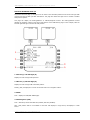
DEPARTURE/ARRIVAL INDEX PAGE
The departure and arrival index page is used to select the departure or arrival page for the origin and
destination airports for each route. The index also allows reference to departure or arrival data for any other
airport in the navigation database.
Departure and arrival prompts are available for the origin airport. Destination airports have only arrival
prompts.
1. Departure (DEP) - Route 1
Push - displays the departure page for route 1 origin airport.
2. Departure (DEP) - Route 2
Push - displays the departure page for route 2 origin airport.
3. Departure (DEP) - Other
Displays the departure page for the airport entered into this line through the scratchpad.
DEP prompt for OTHER allow display of departure data about airports that are not an origin or destination.
The data can be viewed but cannot be selected because the airport is not on the route.
4. Arrival (ARR) - Route 1 Origin
Push - displays the arrival page for route 1 origin airport. Origin airport arrivals selection is used during a
turn-back situation.
© 2011 Captain Sim www.captainsim.com
‘757 Captain’ FLIGHT MANUAL Part V – Flight Management System
DO NOT USE FOR FLIGHT
44
5. Arrival (ARR) - Route 1 Destination
Push - displays the arrival page for route 1 destination airport.
6. Arrival (ARR) - Route 2 Origin
Push — displays the arrival page for route 2 origin airport. Origin airport arrivals selection is used during a
turn-back situation.
7. Arrival (ARR) - Route 2 Destination
Push - displays the arrival page for route 2 destination airport.
8. Arrival (ARR) - Other
Displays the arrival page for the airport entered in this line through the scratchpad.
ARR prompt for OTHER allow display of arrival data about airports that are not an origin or destination.
The data can be viewed but cannot be selected because the airport is not on the route.
DEPARTURES PAGE
The departures page is used to select the departure runway, SID, and transition for the route origin airport.
The departures page for the inactive route displays when the DEP ARR function key is pushed with an
inactive RTE or RTE LEGS page is displayed.
1. Standard Instrument Departures (SIDS)
Displays a list of SIDS for the airport.
Push• selects SID for use in the route
• other SIDs no longer display and transitions for the selected SID display
© 2011 Captain Sim www.captainsim.com
‘757 Captain’ FLIGHT MANUAL Part V – Flight Management System
DO NOT USE FOR FLIGHT
45
• runways for selected SID remain and others no longer display.
2. Transitions (TRANS)
Displays transitions compatible with the selected SID.
Push• selects transition for entry in the route
• other transitions no longer display.
3. ERASE or INDEX
Erase displays when a route modification is pending. INDEX displays when no route modification is pending.
ERASE push - removes selections not executed and displays the entire departure page. Other vertical or
lateral modifications will be erased also.
INDEX push - displays the DEP/ARR INDEX page.
4. RUNWAYS
Displays a list of runways for the selected airport.
The runway selected on the RTE 1/X page displays as <SEL> or <ACT>.
Push• selects runway for use in the route. All other runways no longer display
• SIDs associated with selected runway remain, all others no longer display
• subsequent change of a runway deletes departure procedures previously selected.
5. <SEL>, <ACT>
Selecting an option displays <SEL> inboard of the option and creates a route modification. After executing
the modification, <SEL> becomes <ACT>. Executing a modification or leaving the page and returning
displays all options and the <SEL> or <ACT> prompts.
6. ROUTE
Push - displays the related RTE page.
© 2011 Captain Sim www.captainsim.com
‘757 Captain’ FLIGHT MANUAL Part V – Flight Management System
DO NOT USE FOR FLIGHT
46
NAVIGATION RADIO PAGE
VOR navigation radios are normally autotuned by the FMC. The NAV RADIO page displays the tuned VOR
frequencies, identifiers, tuning status and current radial for both VOR receivers. The VORs can be remotely
tuned from this page.
1. VOR Frequency and Tune Status
The tuning status is displayed adjacent to left and right VOR frequencies. Entry of a frequency or identifier
remotely tunes a VOR. The FMC autotunes VORs and their related DMEs for procedure flying and radio
positions. The tuning status displays are:
• A (autotuning) — FMC selects a navaid for best position orientation
• P (procedure autotuning) - FMC selects navaids for approach or departure procedure guidance
• R (remote tuning) — VOR frequency or identifier has been entered by the flight crew on the NAV
RADIO page.
• M (manual) - VOR is manual-tuned using the VOR control panels on the glareshield. Manual—tuning
takes priority over FMC autotuning.
Valid entries:
•
VOR or non-ILS DME identifier
•
VOR frequency (XXX.X or XXX.XX)
The identifier and frequencies are green and tuning status is white.
2. RADIAL
Displays the current radial from the left and right VOR stations to the airplane.
3-4. ADF Frequency
5. ILS Frequency and Course
The ILS receivers operate in the automatic or manual tuning mode. The FMC commands the frequency and
course selection in the automatic mode. When the ILS is not necessary, the FMC sets the ILS to PARK.
Airplane
position on the route determines the ILS operating mode. The operating mode displays are:
PARK - The ILS is not being used and is not tuned
XXX.XX/YYY PARK - The ILS is tuned for the selected approach but is not being used
“A” indicates autotuning under FMC control for approach guidance.
“M” indicates the ILS is manually tuned.
© 2011 Captain Sim www.captainsim.com
‘757 Captain’ FLIGHT MANUAL Part V – Flight Management System
DO NOT USE FOR FLIGHT
47
ILS manual tuning requires entry of a frequency and course.
NOTE: due to Flight Simulator limitations, entering an ILS frequency also tunes the VOR L radio to the same
frequency. This also happens when the ILS is autotuned. The VOR L tune status indicates P (procedural
autotuning) in this case.
PERFORMANCE INITIALIZATION PAGE
The performance initialization page allows the entry of airplane and route data to initialize performance
calculations. This data is required for VNAV operation.
1. Gross Weight (GRWT)
Airplane gross weight can be entered by the flight crew or calculated by the FMC after entry of zero fuel
weight.
Valid entry is thousands of pounds with a decimal (hundreds) optional.
Entering the zero fuel weight first displays calculated gross weight.
Entry of a value after takeoff speeds are selected removes the speeds and displays the scratchpad message
TAKEOFF SPEEDS DELETED.
2. FUEL
Fuel on board displays when the fuel totalizer calculations are valid. The source for the display is included in
the line:
• CALC (calculated) - fuel quantity is from FMC calculations.
© 2011 Captain Sim www.captainsim.com
‘757 Captain’ FLIGHT MANUAL Part V – Flight Management System
DO NOT USE FOR FLIGHT
48
Valid entry is thousands of pounds with a decimal (hundreds) optional.
3. Zero Fuel Weight (ZFW)
Normally, ZFW is entered from the airplane dispatch papers and the FMC calculates the airplane gross
weight.
Valid entry is thousands of pounds with a decimal (hundreds) optional.
Calculated zero fuel weight displays when airplane gross weight is entered first and fuel on board is valid.
Entry of a value after takeoff speeds are selected removes the speeds and displays the scratchpad message
TAKEOFF SPEEDS DELETED.
4. RESERVES
Valid entry is thousands of pounds with a decimal (hundreds) optional.
5. INDEX
Push - displays the INIT/REF INDEX page.
6. Cruise Altitude (CRZ ALT)
Cruise altitude can be entered by the flight crew or from a company route.
Entered value is displayed on the CLB and CRZ pages.
7. COST INDEX
Cost index is used to calculate ECON climb, cruise, and descent speeds. Larger values increase the ECON
cruise speed. Entering zero results in maximum range airspeed and minimum trip fuel. Cost index can be
entered by the flight crew or from a company route.
Valid entries are 0 to 9999.
8. Cruise Center of Gravity (CRZ CG)
Used by FMC to compute maximum altitude and maneuver margin to buffet.
Displays default center of gravity in small font.
A flight crew entered value displays in large font.
9. STEP SIZE
Displays the climb altitude increment used for planning the optimum climb profile.
Default value is ICAO which provides a 2000 foot step below FL290 and a 4000 foot step above FL290.
Valid manual entries are 0 to 9000 in 1000 foot increments.
In-flight entries are inhibited. In-flight step size changes are made on the CRZ page.
For a non-zero entry, performance predictions are based on step climbs at optimum points. For a zero entry,
performance predictions are based on a constant CRZ ALT.
10. TAKEOFF
Push - displays the TAKEOFF REF page.
© 2011 Captain Sim www.captainsim.com
‘757 Captain’ FLIGHT MANUAL Part V – Flight Management System
DO NOT USE FOR FLIGHT
© 2011 Captain Sim www.captainsim.com
49
‘757 Captain’ FLIGHT MANUAL Part V – Flight Management System
DO NOT USE FOR FLIGHT
50
TAKEOFF REFERENCE PAGE
The takeoff reference page allows the input of the final performance data required for takeoff. Entries on the
takeoff reference page complete the normal FMC preflight. If any required preflight data has been omitted,
prompts are displayed to access the page where data is missing.
1. Flap/Acceleration Height (FLAP/ACCEL HT)
Enter a valid takeoff flap setting.
Entry of a value after takeoff speeds are entered removes the speeds and displays the scratchpad message
TAKEOFF SPEEDS DELETED.
ACCEL HT displays the acceleration height in feet above the origin airport. VNAV commands acceleration at
this altitude or at first flap retraction.
© 2011 Captain Sim www.captainsim.com
‘757 Captain’ FLIGHT MANUAL Part V – Flight Management System
DO NOT USE FOR FLIGHT
51
Default value is from the AMI.
Valid flight crew entries are from 400 to 9999 feet above the origin airport elevation.
2. THRUST
Initially displays dashes and the thrust reference mode.
If an assumed temperature value is entered on the thrust management control panel, the entered
temperature is displayed here.
Valid flight crew entries are from 0 to 99 (°C) or 32F to 21 OF (°F). The entered value is displayed on EICAS.
Entry of a value after takeoff speeds are entered removes the speeds and displays the scratchpad message
TAKEOFF SPEEDS DELETED.
3. INDEX
Push - displays the INIT/REF INDEX page.
4. V Speeds
Dashes are displayed before speeds are entered and when speeds have been deleted.
If performance data is changed after speeds are entered, the speeds are deleted, dashes are displayed,
and the scratchpad message TAKEOFF SPEEDS DELETED is displayed.
5. TRIM, Center of Gravity (CG)
Valid entry is CG within the valid range.
After the CG is entered, the FMC calculates and displays the stabilizer takeoff trim setting to the left of the
CG entry
6. Pre-Flight (PRE-FLT) Status
Displays COMPLETE if all required pre-flight entries have been made.
Displays a prompt to access a pre-flight page where further entries are required if pre—flight is not
complete.
© 2011 Captain Sim www.captainsim.com
‘757 Captain’ FLIGHT MANUAL Part V – Flight Management System
DO NOT USE FOR FLIGHT
52
Section 6: FMC TAKEOFF AND CLIMB
INTRODUCTION
The takeoff phase of flight starts with the selection of takeoff thrust at the start of the takeoff roll.
The takeoff mode of the autoflight system provides flight director guidance until LNAV and VNAV are
engaged after takeoff. Preparation for this phase starts in the preflight phase and includes entry of the
TAKEOFF REF page data.
The takeoff phase changes to the climb phase when climb thrust and VNAV are engaged. The climb phase
continues to the top of climb point, where the cruise phase starts.
TAKEOFF PHASE
When changes are made to the departure runway and SID, the DEPARTURES and TAKEOFF REF pages must
be modified to agree. The modified data are entered the same as during preflight.
During takeoff, the autothrottle commands the selected thrust and the autoflight system provides pitch and
roll commands through the flight director.
FMC roll commands are provided when LNAV is engaged.
CLIMB PHASE
When climb thrust and VNAV are engaged the FMC provides pitch commands to maintain the climb speed
until the acceleration height is reached. At the acceleration height the FMC commands acceleration to 250
knots.
The VNAV commanded speed is limited by the airplane configuration. At acceleration height, VNAV
commands a speed 5 knots below the flap placard speed.
Passing 10,000 feet, VNAV commands an acceleration to the economy climb speed, which is maintained until
reaching the cruise altitude unless the climb profile contains other constraints.
During the climb, VNAV complies with the LEGS page waypoint altitude and speed constraints. A temporary
level-off for a crossing altitude restriction is accomplished at the commanded speed.
© 2011 Captain Sim www.captainsim.com
‘757 Captain’ FLIGHT MANUAL Part V – Flight Management System
DO NOT USE FOR FLIGHT
53
CLIMB PAGE
The climb page is selected by pushing the CDU VNAV function key while on the ground, during takeoff, or in
climb.
The climb page is used to evaluate, monitor, and modify the climb path. The data on the climb page comes
from preflight entries made on the route and performance pages, and from the FMC data bases.
When the airplane reaches the top of climb, the FMC changes to the cruise mode, the cruise page is
displayed and the climb page data is blanked.
The FMC provides speed control in the climb mode to provided the best economy, a fixed speed, or the
engine out speed. In each mode, the same type of data is shown on the page.
1. Page Title
ACT is displayed when the climb phase is active.
The page title displays the type of climb:
• ECON - speed based on the cost index
• LIM SPD - speed based on airplane configuration limiting speed
• MCP SPD - MCP speed intervention selected
• XXXKT - fixed CAS climb speed profile
• M.XXX - fixed Mach climb speed profile
Fixed climb speeds are for:
• climb segment constraints
• waypoint speed constraints
• an altitude constraint associated with a speed constraint
• a speed transition
• a flight crew selected speed.
2. Cruise Altitude (CRZ ALT)
Displays cruise altitude entered on PERF INIT page.
Valid entries are: XXX, XXXX, XXXXX, or FLXXX. Altitude displays in feet or flight level depending on
transition altitude.
3. Economy Speed (ECON SPD), Selected Speed (SEL SPD)
ECON SPD
• economy speed based on cost index
© 2011 Captain Sim www.captainsim.com
‘757 Captain’ FLIGHT MANUAL Part V – Flight Management System
DO NOT USE FOR FLIGHT
54
• shows CAS and Mach values.
SEL SPD
• shows when intermediate level off required below an existing speed constraint
• shows when flight crew enters speed
• CAS or Mach value may be entered.
4. Speed Transition (SPD TRANS)
The speed transition line shows the transition speed/altitude from one of these sources:
• the navigation database value for the origin airport
• a default speed of 250 knots and 10,000 feet.
Not displayed above the transition altitude.
Can be deleted.
5. Speed Restriction (SPD RESTR)
Speed restrictions not associated with specific waypoints are manually entered on this line.
Dashes before entry by flight crew.
Valid entry is a CAS and altitude (example 240/8000).
6. Economy (ECON)
Push - changes climb speed to ECON. Must be executed.
Prompt is shown on line 5L when the climb mode is not ECON.
7. Waypoint Constraint (AT XXXXX)
Displays next airspeed and/or altitude constraint at waypoint XXXXX.
FMC commands the slower of constraint speed or performance speed.
Constraints are entered on RTE LEGS page or are inserted as part of a SID.
Delete here or on RTE LEGS page.
Blank if no constraint exists.
8. Transition Altitude (TRANS ALT)
Transition altitude for origin airport contained in navigation database. FMC uses 18,000 feet if transition
altitude is not available.
Manually change transition altitude here or on DESCENT FORECAST page.
Valid entries are XXX, XXXX, XXXXX, or FLXXX.
Altitude information displayed on the CDU changes from altitudes to flight levels above the transition
altitude.
9. Climb Direct (CLB DIR)
Push - deletes all waypoint altitude constraints between the airplane altitude and the MCP altitude. FMC
cruise altitude is not affected.
Blank if no constraints exist.
© 2011 Captain Sim www.captainsim.com
‘757 Captain’ FLIGHT MANUAL Part V – Flight Management System
DO NOT USE FOR FLIGHT
55
ROUTE LEGS PAGE
The RTE LEGS page is used to evaluate and modify the planned route of flight during the climb and to add or
delete waypoint constraints to comply with the ATC clearance. The data on the RTE LEGS page comes from
preflight entries made on the route and departure pages, and from the FMC data bases.
1. Page Title
Title format shows route status:
• RTE X LEGS - inactive route
• ACT RTE X LEGS - active route
• MOD RTE X LEGS - modified active route.
2. Leg Direction
Leg segment data in line title:
• courses - magnetic (xxx°) or true (xxx° T)
• arcs - distance in miles, ARC, turn direction (example: 24 ARC L)
• heading leg segments — xxx° HDG
• track leg segments — xxx° TRK
• special procedural instructions from database - HOLD AT, PROC TURN.
Calculated great circle route leg directions may be different than chart values.
Dashes are shown for an undefined course.
3. Waypoint Identifier
Shows waypoints by name or condition.
Active leg is always the first line of the first active RTE X LEGS page.
© 2011 Captain Sim www.captainsim.com
‘757 Captain’ FLIGHT MANUAL Part V – Flight Management System
DO NOT USE FOR FLIGHT
56
All route waypoints are shown in flight sequence. Waypoints on an airway are included on the route legs
page.
Waypoints can be modified. Examples:
• add waypoints
• delete waypoints
• change waypoint sequence
• connect route discontinuities.
Boxes are shown for route discontinuities.
Dashes are diplayed on the line following the last waypoint on the route.
4. Route 2 Legs (RTE 2 LEGS)
Push-
• shows the RTE 2 LEGS
• when RTE 2 LEGS page is shown, prompt changes to RTE 1 LEGS.
5. Waypoint Speed/Altitude Constraints
Waypoint speed or altitude constraint in large font.
Manual entry allowed in climb or descent phase. Entered by FMC when constraints are part of a procedure.
Speed constraint is assumed to be at or below the displayed speed.
Valid entries are:
• speed - airspeed or Mach - requires an altitude constraint at the same
• waypoint
• altitude in thousands of feet or flight level (19000, 190)
• XXX/XXXXX - airspeed/altitude entered simultaneously
• XXX/ - airspeed only
• XXXXX or/XXXXX-altitude only.
Altitude constraint suffixes:
• blank - cross at altitude
• A - cross at or above altitude
• B - cross at or below altitude
• both - altitude block. Example: 220A240B
6. Distance to Waypoint
Distance between the waypoints displayed in nautical miles.
The first line displays the distance from the airplane to the active waypoint.
7. Waypoint Speed/Altitude Predictions
Waypoint speed and altitude predictions are displayed in small font.
Dashes are displayed in the descent region prior to descent path calculation.
Descent path calculation requires altitude constraint below cruise altitude.
8. ACTIVATE, Route Data (RTE DATA)
Push - three possible prompts
• ACTIVATE - activates inactive flight plan; shows RTE DATA prompt
• RTE DATA - shows route data page
• STEP - changes the center point on the HSI map in the PLAN mode.
9. Center (<CTR>)
© 2011 Captain Sim www.captainsim.com
‘757 Captain’ FLIGHT MANUAL Part V – Flight Management System
DO NOT USE FOR FLIGHT
57
Displays when PLAN mode selected.
Displays adjacent to the waypoint around which HSI plan mode is centered.
10. MAP Center (CTR) STEP
Replaces ACTIVATE or RTE DATA when PLAN mode selected.
Push - steps <CTR> to next waypoint. HSI plan mode recenters.
AIR TURN-BACK
ARRIVALS PAGE
During a turn-back situation, the flight crew requires quick access to the arrivals data for the origin airport.
The arrivals page allows access without changing the destination on the route page.
During climb if the airplane is less than 400 miles from the origin and less that half way to the destination,
push the DEP ARR key to show the ARRIVALS page for the origin airport.
1. Standard Terminal Arrivals (STARS)
Shows STARS for origin airport.
2. Transitions (TRANS)
Shows transitions for origin airport.
3. APPROACHES
Shows approaches for origin airport.
4. RUNWAYS
Shows runways for origin airport.
The arrivals page is discussed in more detail in the Descent and Approach Section (11.43) of this chapter.
© 2011 Captain Sim www.captainsim.com
‘757 Captain’ FLIGHT MANUAL Part V – Flight Management System
DO NOT USE FOR FLIGHT
58
Section 7: FMC CRUISE
INTRODUCTION
The cruise phase starts at the top of climb.
During cruise, the primary FMC pages are:
• RTEXLEGS
• CRZ
• PROGRESS.
The RTE LEGS pages are used to modify the route. The CRZ pages display VNAV related data. The
PROGRESS pages display flight progress data. During cruise, the specific page listed below is used to:
• POS REF page - verify the FMC position
• RTE DATA page - display progress data for each waypoint on the RTE LEGS page
• REF NAV DATA page - display data about waypoints, navaids, airports, or runways, and can be used
to inhibit navaids
• RTE page - select a route offset
• FIX INFO page - display position data about waypoints. Position data can be transferred to other
pages to create new waypoints and fixes
• SELECT DESIRED WAYPOINT page - shows a list of duplicate waypoints from the navigation
database. The flight crew selects the correct waypoint from the list
• POS REPORT page - display data for a position report.
The CLB page changes to CRZ at the top of climb. The CRZ CLB and CRZ DES pages change to CRZ when a
new cruise altitude is reached. The CRZ page changes to DES at top of descent.
LNAV MODIFICATIONS
This section shows typical techniques to modify the route. The modifications include:
• add and delete waypoints
• change waypoint's sequence
• connect discontinuities
RTE LEGS PAGE MODIFICATIONS
Modifications to the LNAV route are usually made on the RTE LEGS page. When the route is modified, MOD is
displayed in the title and the execute light is illuminated.
© 2011 Captain Sim www.captainsim.com
‘757 Captain’ FLIGHT MANUAL Part V – Flight Management System
DO NOT USE FOR FLIGHT
59
ADD WAYPOINTS
Waypoints can be added to the route at any point. Added waypoints are followed by route discontinuities.
First, enter the waypoint name in the scratchpad.
Second, locate the correct line in the flight plan and push the adjacent line select key. The scratchpad
waypoint name is put into the selected line. The entered waypoint is connected to the waypoint above it via
a direct route. A route discontinuity follows the waypoint.
For example, OED is typed into the scratchpad. Push line select key 2L to put OED into line 2. The FMC
assumes BTG direct OED. RBL and the rest of the flight plan are kept but, are put after the route
discontinuity.
1. Page Title
MOD — replaces ACT when modification is in progress.
ACT - replaces MOD when ERASE is selected or execute key is pushed.
2. Modified Waypoint
OED waypoint entered into the route after BTG Modification creates a route discontinuity because OED was
not in the active route. The FMC now requires routing beyond OED.
3. Discontinuity
Discontinuity is corrected when applicable waypoint is entered in boxes.
4. ERASE
Push - removes all modifications and shows active data.
Displayed when the FMC contains modified data.
Removed when the modifications are executed.
5. ROUTE DISCONTINUITY
Line title separates route segments when there is a discontinuity.
© 2011 Captain Sim www.captainsim.com
‘757 Captain’ FLIGHT MANUAL Part V – Flight Management System
DO NOT USE FOR FLIGHT
60
Note
Performance predictions to destination on the PROGRESS page are calculated assuming the
route of flight is direct between waypoints on either side of a route discontinuity.
DELETE WAYPOINTS
Use the RTE LEGS page to remove waypoints from the route. The active waypoint can not be deleted. Two
methods to remove a waypoint are:
• delete the waypoint with the DEL function key
• change the sequence of other waypoints.
The data in the route before the deleted waypoint does not change. A discontinuity is put in the route when
the DEL function key is used to remove a waypoint.
1. Active Route
The active route shows RBL followed by OAK and AVE.
2. DELETE Entry
Pushing the DEL function key arms the delete function and selects DELETE to the scratchpad.
3. Discontinuity
With DELETE in the scratchpad, pushing the line select key for RBL deletes the waypoint. Boxes replace RBL
and a route discontinuity is displayed.
© 2011 Captain Sim www.captainsim.com
‘757 Captain’ FLIGHT MANUAL Part V – Flight Management System
DO NOT USE FOR FLIGHT
61
CHANGE WAYPOINT SEQUENCE
Waypoints moved from one position in the flight plan to another do not cause route discontinuities.
The waypoint may be manually typed or copied from any of the RTE LEGS pages. To copy the waypoint,
push the line select key adjacent to the waypoint.
The example below shows the flight plan being modified to fly from BTG direct OAK. Push the line select key
adjacent to OAK to put OAK in the scratchpad. Push the line select key adjacent to RBL. RBL is removed
from the flight plan and the routing is direct from BTG to OAK to AVE. The modification does not cause a
route discontinuity. Several waypoints can be removed from the flight plan at a time with this method.
1. Active Route
The active route shows RBL followed by OAK and AVE. The clearance is to fly from BTG direct OAK. The OAK
waypoint is selected to the scratchpad.
2. Change OAK's Sequence
OAK is selected to the waypoint after BTG RBL is removed with no discontinuity.
© 2011 Captain Sim www.captainsim.com
‘757 Captain’ FLIGHT MANUAL Part V – Flight Management System
DO NOT USE FOR FLIGHT
62
REMOVE DISCONTINUITIES
A discontinuity exists when two waypoints are not connected by a route segment.
To remove a discontinuity, copy the subsequent waypoint from the route into the scratchpad and enter it
into the discontinuity.
1. Discontinuity
The active route has a discontinuity after BTG The example shows how to fly direct from BTG to OAK. Copy
OAK to the scratchpad. Any subsequent waypoint in the route can be selected to the scratchpad to remove
the discontinuity.
2. Continuous Route
Select OAK to the boxes to remove the discontinuity.
If a waypoint which does not already exist on the route is entered into the boxes the discontinuity moves
one waypoint further down the route.
© 2011 Captain Sim www.captainsim.com
‘757 Captain’ FLIGHT MANUAL Part V – Flight Management System
DO NOT USE FOR FLIGHT
63
DIRECT TO
If the airplane is not on the active leg segment, LNAV may deactivate or it may not activate when armed.
This happens after the airplane crosses a discontinuity, or is not on an intercept heading to the active leg
segment. Here are three ways to arm or activate LNAV:
• When the airplane is within 2.5 miles of the active leg, push the LNAV switch. LNAV activates and
intercepts the active route leg.
• When more than 2.5 miles from the active leg, push the LNAV switch when the airplane is on an
intercept heading to the active route leg. Initially, LNAV arms and then activates as the airplane
approaches the active leg. An intercept heading must intersect the active leg inbound before the
active waypoint.
MODIFICATION OF THE ACTIVE WAYPOINT
The example below depicts the airplane being off course to the right, followed by a modification to fly direct
to BTG.
1. Course to Active Waypoint
Displays current required track to fly inbound course to waypoint.
2. Active Waypoint
Displays crew entered direct/intercept waypoint. If entered waypoint is not part of the active route it will be
followed by a discontinuity.
© 2011 Captain Sim www.captainsim.com
‘757 Captain’ FLIGHT MANUAL Part V – Flight Management System
DO NOT USE FOR FLIGHT
64
SELECT DESIRED WAYPOINT (WPT) PAGE
The SELECT DESIRED WPT page is displayed when a waypoint identifier or name is entered and the
navigation database contains more than one location for the same waypoint name. Selection of a waypoint
returns the display to the previous page.
1. Identifier
Displays a list of the waypoints in the navigation database that have the same identifier as entered.
Up to 48 waypoints (8 pages) can be listed.
Waypoints are sorted as follows:
• when page is accessed as a result of a flight plan entry or modification, sort is based on proximity
to the waypoint preceding the entered waypoint
• when page is accessed as a result of a DIR/INTC, FIX INFO, or REF NAV DATA entry, sort is based
on proximity to current aircraft position.
Select the desired waypoint by pushing either the left or right line select key adjacent to the waypoint. The
CDU page where the waypoint identifier was entered is then displayed with the selected waypoint inserted.
2. Frequency
Displays frequency of the waypoint if it is a navaid. Blank if the waypoint is not a navaid.
3. Type
Displays the type of waypoint for each duplicate name.
4. Latitude/Longitude
Displays the latitude/longitude for each duplicate name.
© 2011 Captain Sim www.captainsim.com
‘757 Captain’ FLIGHT MANUAL Part V – Flight Management System
DO NOT USE FOR FLIGHT
65
CRUISE PAGE
The cruise page is used to monitor and change cruise altitude and speed. Speed changes can be manually
selected or automatically selected with the selection of other VNAV modes. Cruise climbs, cruise descents,
and step climbs can be accomplished from the cruise page.
When using the economy mode, page data is based on operating at ECON SPD. Economy cruise speed is
based on cost index. When the flight crew enters a selected speed, page data changes. When the FMC is in
the engine out mode, the data changes to include the airplane capabilities with one engine inoperative. The
long range cruise (LRC) mode calculates speeds to maximize airplane range.
1. Page Title
The page title displays active (ACT) or modified (MOD) cruise. Usually, the title contains ECON for economy
cruise. Fixed speed, engine out, and long range cruise modify the title.
Page titles include:
• CRZ CLB or CRZ DES - cruise climb or descent
• ECON - speed based on cost index
• LIM SPD - based on an airplane configuration limiting speed
• LRC - long range cruise selected
• MCP SPD - speed intervention applied from the MCP
• M.XXX - fixed Mach cruise speed
• XXXKT - fixed CAS cruise speed.
Fixed cruise speeds are for:
• waypoint speed constraints
• an altitude constraint associated with a speed constraint
• a flight crew selected speed (SEL SPD).
2. Cruise Altitude (CRZ ALT)
Displays cruise altitude entered on PERF INIT page.
Valid entries are: XXX, XXXX, XXXXX, OR FLXXX. Altitude displays in feet or flight level depending on the
transition altitude. Changing the MCP altitude enters the new altitude in the scratchpad for entry. Entry
creates a modification.
When the modification is executed the page title changes to CRZ CLB or CRZ DES.
© 2011 Captain Sim www.captainsim.com
‘757 Captain’ FLIGHT MANUAL Part V – Flight Management System
DO NOT USE FOR FLIGHT
66
3. Economy Speed (ECON SPD), Selected Speed (SEL SPD)
Displays target speed or Mach.
MOD displays in the page title until the modification is erased or executed.
A manually entered speed changes the line title to SEL SPD.
ECON can be replaced with LRC or company (CO SPD), depending on the VNAV mode.
4. EPR
Displays EPR necessary for level flight at the target airspeed.
5. Economy (ECON)
Blank when ECON is the active speed. Displays a prompt when ECON is not the active speed.
Push - selects economy cruise speed.
6. Destination ETA/FUEL
Estimated time of arrival and calculated fuel remaining at the destination.
Displays the same data for the alternate airport when a DIVERT NOW modification is selected from the ALTN
page.
Calculations are based on optimum step climbs and cruise altitudes.
VNAV MODIFICATIONS
During the cruise phase, VNAV can calculate two types of climbs: cruise climbs and step climbs. Cruise
climbs can be entered by the flight crew. Optimum step climbs are calculated by the FMC. In all cases, the
new climb altitude must be selected in the MCP altitude window before VNAV commands the climb.
CRUISE CLIMB
To initiate a cruise climb set the higher altitude on the MCP, then enter the altitude in the CRZ ALT line and
execute. When the CRZ page is displayed, the new MCP altitude is automatically copied to the scratchpad to
be line selected to the CRZ ALT line.
1. During Cruise Climb
VNAV page title displays ACT ECON CRZ CLB in a climb to a new cruise altitude. ECON is replaced by the
selected speed if other than ECON.
2. End of Cruise Climb
© 2011 Captain Sim www.captainsim.com
‘757 Captain’ FLIGHT MANUAL Part V – Flight Management System
DO NOT USE FOR FLIGHT
VNAV page title returns to ECON CRZ after level off at cruise altitude.
© 2011 Captain Sim www.captainsim.com
67
‘757 Captain’ FLIGHT MANUAL Part V – Flight Management System
DO NOT USE FOR FLIGHT
68
CALCULATED STEP CLIMB
When a non-zero value is entered into the STEP SIZE line on the PERF INIT or CRZ page, the FMC calculates
optimum points for step climbs as the airplane performance permits. The climb altitude is determined by the
value in STEP SIZE. Multiple step climbs are possible based on performance and route length. VNAV
commands the step climbs if the MCP altitude and the FMC CRZ ALT are set to the new altitude.
1. TO STEP CLIMB
When the step climb start point is the next VNAV event, the line title changes to TO STEP CLIMB.
Displays the ETA and DTG to the point where the step climb starts.
If the airplane passes the step climb point and has not started to climb, the ETA and DTG are replaced with
the word NOW.
When the FMC calculates that a step climb is not advised, the ETA and DTG are replaced with the word
NONE.
2. STEP SIZE
Displays the default step climb size of ICAO.
Valid entries are altitudes from 0 to 9000 in 1000 foot increments.
Used for calculation of optimum step point and step climb predictions.
Deletion of a manual entry defaults back to ICAO.
© 2011 Captain Sim www.captainsim.com
‘757 Captain’ FLIGHT MANUAL Part V – Flight Management System
DO NOT USE FOR FLIGHT
69
3. STEP TO
Displays a calculated step climb altitude based on the step size.
Blank when:
• there is no active flight plan
• less than 200 NM from the T/D point
• less than 500NM from the destination
• step size is zero
4. AT
Displays the ETA and DTG to the step climb point.
Displays NOW when past the calculated step climb point.
Line title changes to TO T/D when within 200 NM of the top of descent point. ETA and DTG are relative to the
T/D point.
The data is the same as displayed on the PROGRESS page.
5. Optimum Altitude and Maximum Altitude (OPT MAX)
OPT - displays the most economical altitude to fly based on gross weight and the active cruise speed.
MAX — displays the two engine maximum altitude based on gross weight, climb and cruise speeds within the
speed envelope, and sufficient excess thrust to provide a specified residual rate of climb capability.
CRUISE DESCENT
Cruise descents can be started in the cruise phase when the airplane is more than 50 miles from the T/D
point.
A cruise descent can be started by selecting a lower altitude on the MCP, entering the new altitude in the
CRZ ALT line and executing. A VNAV cruise descent is commanded at the current cruise speed and
approximately 1250 feet per minute rate of descent.
The autothrottles adjust thrust to maintain the target descent rate; pitch maintains the commanded speed.
Thrust levers can be manually positioned to adjust the descent rate.
1. During Cruise Descent
VNAV page title shows cruise phase in a descent to a new cruise altitude.
2. End of Cruise Descent
VNAV page title shows cruise phase after level off at new cruise altitude.
© 2011 Captain Sim www.captainsim.com
‘757 Captain’ FLIGHT MANUAL Part V – Flight Management System
DO NOT USE FOR FLIGHT
70
EARLY DESCENT
An early descent starts when the descent for landing is commenced prior to the FMC calculated top of
descent (T/D) point. Early descents should not be started when the distance to the T/D is greater than 50
nautical miles. When further from the top of descent point, the cruise descent function should be used.
Early descents are started on the DES page. Once an early descent is started, VNAV changes to the descent
phase and cruise features are no longer available.
The autothrottle adjusts thrust to maintain the target descent rate; pitch maintains the commanded speed.
Thrust levers can be manually positioned to adjust the descent rate.
1. Descend Now (DES NOW)
The DES NOW prompt is shown on the descent page when the cruise phase is active. Reset the MCP altitude
and select the DES NOW prompt and execute to start an early descent. The descent page becomes active
and the airplane starts a VNAV ECON descent at ECON descent speed.
Upon reaching the planned descent path, VNAV commands pitch to maintain the planned descent path and
ECON speed.
© 2011 Captain Sim www.captainsim.com
‘757 Captain’ FLIGHT MANUAL Part V – Flight Management System
DO NOT USE FOR FLIGHT
71
NAVIGATION DATA
REFERENCE NAVIGATION DATA PAGE
The reference navigation data page displays data about waypoints, navaids, airports, and runways. Use this
page to inhibit FMC position updates from radio navaids.
1. Identifier (IDENT)
Valid entries are any waypoint, navaid, airport, or runway from the navigation database. Only runways at
the destination airport can be entered.
Entry changes to dashes when page is exited and then reselected.
2. LATITUDE
Displays latitude of entered identifier. When the identifier is a runway the latitude displayed is for the
threshold of the runway.
3. Magnetic Variation (MAG VAR), LENGTH
MAG VAR - displays magnetic variation when entered identifier is a navaid.
LENGTH - displays runway length when entered identifier is a runway.
4. INDEX
Push - displays the INIT/REF INDEX page.
5. Frequency (FREQ)
Displays frequency of entered identifier when it is a navaid.
© 2011 Captain Sim www.captainsim.com
‘757 Captain’ FLIGHT MANUAL Part V – Flight Management System
DO NOT USE FOR FLIGHT
72
6. LONGITUDE
Displays longitude of entered identifier. When the identifier is a runway the longitude displayed is for the
threshold of the runway.
7. ELEVATION
Displays elevation of entered identifier when it is a navaid, airport, or runway.
8. VOR/DME NAV
Alternately switches VOR/DME NAV updating between OFF and ON.
FIX INFORMATION PAGE
Two identical fix information pages are used to create fixes and waypoints for the HSI. Some of the created
waypoints can be copied into the route.
© 2011 Captain Sim www.captainsim.com
‘757 Captain’ FLIGHT MANUAL Part V – Flight Management System
DO NOT USE FOR FLIGHT
73
1. FIX
Before entry of a name or identifier, boxes displayed and most data lines are blank.
Valid entries are airports, navaids, and waypoints from the navigation database. The selected fix displays on
the HSI and is highlighted by a green circle.
2. Bearing/Distance (BRG/DIS), ETA, DTG, ALT
Valid entries are XXX/YYY.Y:
• decimal values can be omitted
• leading zeros can be omitted for distance entries
• distance only entries must start with a slash (/).
Distances from the fix display on the HSI as a circle around the fix.
When the circle intersects the active route, the ETA, DTG, and predicted altitude at the intersection display
for the closest of the two intersections.
Bearings from the fix display on the HSI as radial lines from the fix.
When the bearing intersects the active route, the ETA, DTG, and predicted altitude at the intersection
display.
ETA - displays the estimated time of arrival to the intersection point.
DTG - displays the distance to go to the intersection point.
ALT - displays the predicted altitude at the intersection point.
Push - copies the fix place/bearing/distance into the scratchpad. This fix can be placed in the route on a
LEGS or RTE page as a waypoint.
3. Bearing/Distance (BRG/DIS) - Dashes
Enter a bearing, distance, or both bearing and distance from the fix. A bearing and distance from the fix
displays on the HSI as a waypoint fix point. ETA, DTG, and predicted do not display.
4. ABEAM
Displays ABEAM prompt.
Push - displays bearing and distance from the fix perpendicular to the nearest segment of the flight plan
path, and ETA, DTG, and altitude at the intersection point.
Second push - copies the fix place/bearing/distance into the scratchpad. This fix can be placed in the route
on a LEGS or RTE page as a waypoint.
5. ERASE FIX
Push - removes all fix data from the page and the HSI.
6. Route Intersection Point Copied
Pushing the line select key for one of the BRG/DIS entries copies the fix place/bearing/distance definition
into the scratchpad. This fix can be placed into the route on a LEGS page as a waypoint.
7. Bearing/Distance From (BRG/DIS FR)
Displays the bearing and distance of the airplane from the fix.
© 2011 Captain Sim www.captainsim.com
‘757 Captain’ FLIGHT MANUAL Part V – Flight Management System
DO NOT USE FOR FLIGHT
74
IN-FLIGHT POSITION UPDATE
FMC position update can be accomplished on the POS REF 2/3 page in flight.
1. UPDATE ARMED
Pushing the ARM prompt arms the position update function. ARM changes to ARMED. Each of the position
update sources have a NOW prompt.
2. NOW
Push - to update the FMC position from the desired source. The FMC position is changed to the position of
the selected system. If a valid source with a more accurate position (smaller ACTUAL) exists, the FMC
position will quickly return to the most accurate position source.
© 2011 Captain Sim www.captainsim.com
‘757 Captain’ FLIGHT MANUAL Part V – Flight Management System
DO NOT USE FOR FLIGHT
75
ROUTE AND WAYPOINT DATA
ROUTE DATA PAGE
The route data page displays progress data for each waypoint on the ACT RTE X LEGS page. This page is
available only for the active route.
The ETA and calculated fuel remaining are displayed for each waypoint. Manual entry is not possible.
One page shows data for five waypoints.
1. Waypoint (WPT)
Displays identifier for waypoint.
2. ETA
Displays ETA for waypoint.
3. FUEL
Displays the FMC calculated fuel remaining at the waypoint.
Note
ETA and estimated fuel calculations assume a direct flight across route discontinuities.
4. WIND Page Prompts
Push - selects WIND page for the selected waypoint.
A "W" next to the prompt indicates that wind data has been entered on the wind page for that waypoint.
© 2011 Captain Sim www.captainsim.com
‘757 Captain’ FLIGHT MANUAL Part V – Flight Management System
DO NOT USE FOR FLIGHT
76
5. LEGS
Push - displays RTE LEGS page.
WIND DATA
The FMC uses wind data to improve performance calculation accuracy.
The FMC applies the first entered wind to all waypoints in the flight plan. Wind data includes altitude and
direction/speed.
Wind data entered at another waypoint changes the wind only for the waypoints down track from that
waypoint either to the end of the track, or to the next entered wind. Therefore, enter winds for waypoints
closest to the airplane first, then enter winds for waypoints further down track.
For example: at FL 350, 100°/085 is entered at waypoint OED. All waypoints in the route have the OED wind
data. Then, additional wind data entered at OAK changes the wind data at OAK and through the end of the
route.
Entered winds are mixed with sensed winds for performance calculations. The FMC uses entered winds for
predictions far ahead of the airplane and sensed winds close to the airplane. The FMC mixes these winds for
predictions in between. Sensed winds are displayed on the HSI and on progress page 2.
WIND PAGE
The wind page is used to enter forecast winds and temperatures at specific altitudes for specific waypoints to
enhance VNAV performance. The FMC calculates step climb points based on the wind effect.
The wind page displays waypoint wind data for one to four altitudes per waypoint. This data can be uplinked
or manually entered.
The altitudes are entered first. The altitudes can be entered in any order and are sorted and displayed in
ascending order.
Wind speed and direction are entered for the specific altitudes.
OAT can be entered for any one altitude. The FMC calculates the temperature for the entered altitudes using
the standard lapse rate.
© 2011 Captain Sim www.captainsim.com
‘757 Captain’ FLIGHT MANUAL Part V – Flight Management System
DO NOT USE FOR FLIGHT
77
1. Page Title
Displays ACT XXXXX, where XXXXX is the waypoint for which the wind page was selected.
When a route is being modified, MOD in is shown in the page title. If ACT is displayed when the wind page is
first accessed, entry of wind data caused MOD to be displayed. Wind entries must be executed.
2. Altitude (ALT)
Enter altitude or flight level for wind entries. Altitude data entry is possible only on line 1L.
After altitude entry, data is sorted in ascending order in lines 1 through 4. Dashes display on right side of
line for wind direction and speed entry.
When all four lines have data, one must be deleted before new data can be entered.
Entered altitudes are propagated to all wind pages.
3. Altitude/Flight Level Data
Displays the altitude or flight level for wind entries. Data entered on 1L is displayed on lines 1 through 4 in
ascending order. Altitude entry is not possible in lines 2L through 4L.
Calculated OAT based on standard lapse rate from the entry made on the ALT/OAT line are display in small
font.
4. ERASE
Push - removes modified data.
© 2011 Captain Sim www.captainsim.com
‘757 Captain’ FLIGHT MANUAL Part V – Flight Management System
DO NOT USE FOR FLIGHT
78
5. Direction and Speed (DIR/SPD)
Displays dashes after altitude/flight level entry in the ALT line. Enter predicted wind direction and speed for
the altitude.
Values propagate to other waypoint winds. Propagated values display in small font.
Manual entries display in large font.
6. Altitude/Outside Air Temperature (ALT/OAT)
Enter altitude and OAT. The altitude for OAT does not have to be one of the wind altitudes. The FMC uses
standard lapse rate to calculate the temperature at the other altitudes.
Entries must be executed.
7. Route Data (RTE DATA)
Push - displays the RTE DATA page.
PROGRESS PAGES
The progress page displays general flight progress data.
PROGRESS PAGE 1
Page one of the progress pages displays general data about:
• waypoints (active and next)
• destination
• FMC speed
• next VNAV profile point.
The page title displays the company flight number entered on the RTE page.
1. TO
Active waypoint is displayed. Can not be modified.
© 2011 Captain Sim www.captainsim.com
‘757 Captain’ FLIGHT MANUAL Part V – Flight Management System
DO NOT USE FOR FLIGHT
79
2. NEXT
Waypoint after TO waypoint is displayed.
Can not be modified.
3. Destination (DEST)
When the page is selected the active route destination is displayed. Any waypoint or airport in navigation
database can be entered over the destination.
The line titles are:
• DEST - performance predictions to destination. Default display.
• DIR TO FIX - when entered waypoint is not in flight plan. Data is based on flying present position
direct to the waypoint.
• EN ROUTE WPT - when entered waypoint is in flight plan. Line data are based on flying the flight
plan route to the waypoint.
• MOD - a modification has been made on another page. Performance predictions include
modification.
Entries do not modify the active route and are deleted when CDU is changed to a different page.
4. Selected Speed (SEL SPD)
Displays the FMC active command speed.
The active speed mode is the same as on the performance page, unless changed by the MCP or a limit. The
speed modes are:
• LRC SPD - long range cruise speed
• ECON SPD - economy speed
• SEL SPD - selected speed manually entered on the CDU
• LIM SPD - speed is limited by VMO, MMO, flap limit, or buffet limit
• MCP SPD - MCP speed IAS/MACH indicator
5. Position Report (POS REPORT)
Push - displays the POS REPORT page.
6. ETA
Estimated time of arrival at waypoint or destination.
7. Distance To Go (DTG)
Distance to go to waypoint or destination.
8. FUEL
Estimated fuel remaining at waypoint or destination.
9. TO Top Of Descent (T/D)
ETA and DTG to next VNAV profile point.
The line
•
•
•
•
title and data change for other phases of flight. Other line titles:
TO T/C-top of climb data
TO STEP CLIMB - step climb data
TO E/D-end of descent data
LEVEL AT - time and distance to level off in engine out mode.
© 2011 Captain Sim www.captainsim.com
‘757 Captain’ FLIGHT MANUAL Part V – Flight Management System
DO NOT USE FOR FLIGHT
10. Position Reference (POS REF)
Push - displays the position reference page.
PROGRESS PAGE 2
Progress page two contains:
• wind data
• true airspeed
• fuel data
• track error data
• static air temperature.
1. Headwind (HAVIND), Tailwind (TAVIND)
Displays headwind (HAVIND) or tailwind (TAVIND) component relative to the airplane heading.
2. Crosstrack Error (XTK ERROR)
Displays crosstrack (XTK) error in nautical miles left or right of the active route.
3. TAS
Displays airplane true airspeed.
4. LEFT FUEL USED
Displays fuel used by left engine sensed by fuel flow meters.
© 2011 Captain Sim www.captainsim.com
80
‘757 Captain’ FLIGHT MANUAL Part V – Flight Management System
DO NOT USE FOR FLIGHT
81
5. Fuel Quantity (QTY) TOTALIZER
Displays total fuel quantity from the fuel system quantity processor.
The fuel remaining line displays two independent fuel remaining values, TOTALIZER and CALCULATED. They
can be compared to validate FMC calculations.
6. WIND
Displays current wind direction and speed referenced to true north.
7. Crosswind (X/WIND)
Displays left (L) or right (R) crosswind component relative to airplane heading.
8. Vertical Track Error (VTK ERROR)
Displays vertical path (VTK) error above (+) or below (-) vertical path.
9. Static Air Temperature (SAT)
Displays outside static air temperature.
10. RIGHT FUEL USED
Displays fuel used by right engine sensed by fuel flow meters.
11. FUEL USED Total (TOT)
Displays sum of the LEFT and RIGHT fuel used values.
12. FUEL Quantity (QTY)
© 2011 Captain Sim www.captainsim.com
‘757 Captain’ FLIGHT MANUAL Part V – Flight Management System
DO NOT USE FOR FLIGHT
82
POSITION REPORT PAGE
The position report page displays data for a position report. A data linked position report can be initiated
from the page.
The page contains reference data only. Manual entries are inhibited.
1. Position (POS)
Waypoint used to report position. This is the previous active waypoint. The actual time of arrival (ATA) and
altitude (ALT) at the waypoint follow the waypoint name.
2. Estimate (EST)
The active waypoint is displayed with the ETA to that waypoint.
3. NEXT
The waypoint following the active waypoint.
4. Temperature and Wind (TEMP WIND)
TEMP displays the OAT in degrees C.
WEND displays the wind direction and speed. Wind direction is shown in degrees true.
5. Destination ETA (DEST ETA)
The FMC calculated ETA for the destination is displayed.
© 2011 Captain Sim www.captainsim.com
‘757 Captain’ FLIGHT MANUAL Part V – Flight Management System
DO NOT USE FOR FLIGHT
6. Speed (SPD)
Displays the target FMC speed.
7. Position Fuel (POS FUEL)
Displays the fuel on board at the POS waypoint.
© 2011 Captain Sim www.captainsim.com
83
‘757 Captain’ FLIGHT MANUAL Part V – Flight Management System
DO NOT USE FOR FLIGHT
84
Section 8: FMC DESCENT AND APPROACH
INTRODUCTION
The descent phase starts at the top of descent point and continues to the end of descent point. Planning for
the descent phase starts during cruise.
The approach phase starts at the end of descent point and continues to touchdown.
The only automatic page change in the descent/approach phases is the VNAV selected page change, from
cruise to descent, at the top of descent.
EARLY DESCENT
Early descent is commenced before reaching the top of descent.
© 2011 Captain Sim www.captainsim.com
‘757 Captain’ FLIGHT MANUAL Part V – Flight Management System
DO NOT USE FOR FLIGHT
85
DESCENT
During descent, LNAV progress is managed using the RTE LEGS page, as in the cruise phase. VNAV descent
management is accomplished primarily on the DES page.
DESCENT PAGE
The descent page is used to monitor and revise the descent path. Descent speed modes are economy
(ECON) and fixed speed (SEL). The default VNAV descent mode is ECON. A fixed speed descent is flown
when speed intervention is used or a speed is entered on the DES page. The descent page is no longer
available after the end of descent.
The page title includes the VNAV speed mode. The ECON mode controls descent speed at the economy
speed until reaching a lower speed restriction. The fixed speed mode controls descent speed until a lower
speed restriction is reached.
1. Page Title
The title usually shows ECON during descent. Fixed speed descents modify the title.
The page title shows the type of descent:
• ECON - speed based on a cost index
• LIM SPD - speed based on airplane configuration limiting speed
• MCP SPD - MCP speed intervention is selected
• XXXKT - fixed CAS descent speed profile
• M.XXX - fixed Mach descent speed profile
• ACT - prefix shown when descent phase is active
• MOD - prefix shown when descent phase is active and the flight plan is modified.
Reasons
•
•
•
•
for fixed descent speeds are:
waypoint speed constraints
an altitude constraint associated with a speed constraint
a speed transition
a flight crew entered selected speed (SEL SPD).
© 2011 Captain Sim www.captainsim.com
‘757 Captain’ FLIGHT MANUAL Part V – Flight Management System
DO NOT USE FOR FLIGHT
86
2. End of Descent At (E/D AT)
Shows the end of descent altitude and waypoint.
The end of descent point is a waypoint in the descent phase with the lowest altitude constraint.
Blank if no E/D point exists.
3. Economy Speed (ECON SPD), Selected Speed (SEL SPD)
Shows the current target descent speed.
ECON SPD • economy speed based on cost index
• shows CAS or Mach.
SEL SPD • shows when intermediate level off required below an existing speed constraint
• shows when flight crew enters speed
• CAS or Mach value may be entered.
• page title changes to ACT XXXKT DES or ACT M.XXX DES
• <ECON prompt appears at line 5L to allow selection of economy descent speed
4. Speed Transition (SPD TRANS)
The transition speed is usually 10 knots less than the destination airport limiting speed from the navigation
database. When no airport limit speed exists, the default speed of 240 knots is shown. The transition altitude
is the point that the transition speed is active for the destination airport. When no altitude exists in the
navigation database, the default of 10,000 feet is shown.
Blanks when the transition has occurred.
Can be deleted.
5. Speed Restriction (SPD RESTR)
Speed restrictions not associated with specific waypoints are manually entered on this line.
Dashes before entry by flight crew.
Valid entry is a CAS and altitude (example 240/8000).
An entry creates a modification.
6. ATXXXXX
Shows the next waypoint constraint from the RTE LEGS page.
Line title shows:
• AT XXXXX (the waypoint identifier)
• HOLD AT XXXXX
• AT VECTORS
• AT(INTC).
The constraint is speed/altitude. Blank when no constraint exists.
Can be deleted on this page.
VNAV commands the lesser of constraint speed or present performance speed.
© 2011 Captain Sim www.captainsim.com
‘757 Captain’ FLIGHT MANUAL Part V – Flight Management System
DO NOT USE FOR FLIGHT
87
8. FORECAST
Push - shows the DESCENT FORECAST page.
7. Descend Direct (DES DIR)
Push - deletes all waypoint altitude constraints between the airplane altitude and the MCP altitude.
Shown in descent phase with altitude constraint between airplane and E/D.
9. Descend Now (DES NOW)
Shown when the descent phase is not active.
Push-
• starts a 1250 feet per minute descent schedule until intercepting the planned descent path
• activates the FMC descent phase.
DESCENT FORECAST PAGE
The descent forecast page is used to enter wind data for descent, and the altitude at which anti-ice use is
anticipated for more accurate descent path calculation.
The primary entries are wind direction and speed for up to four descent altitudes, and the altitude that antiice is turned on.
1. Transition Level (TRANS LVL)
Shows the transition level.
© 2011 Captain Sim www.captainsim.com
‘757 Captain’ FLIGHT MANUAL Part V – Flight Management System
DO NOT USE FOR FLIGHT
88
The transition level can be specified by the arrival procedure. The default transition level is FL 180.
Above transition level, altitudes are in flight levels. Below transition level, altitudes are in thousands of feet.
Valid entry is an altitude or flight level.
2. Altitude (ALT)
Enter altitude of forecast wind data.
Altitudes and flight levels can be entered in any order. Entries are not sorted.
Execute not necessary.
3. Thermal Anti-Ice On Altitude (TAI/ON ALT)
Enter the altitude where anti-ice is first turned on during the descent. The FMC calculates the descent profile
based on the higher thrust caused by thermal anti-ice operation below this altitude.
4. Wind Direction/Speed (WIND DIR/SPD)
Enter the wind direction/speed for the specified altitude. Initial entry must have wind direction and speed,
subsequent entries may have one or the other.
Execute not necessary.
5. Descent (DES)
Push - shows the DES page.
APPROACH
During approach, roll and pitch modes usually change to the approach guidance supplied by navigation
radios. The FMC continues to calculate and show present position and can supply LNAV and VNAV approach
guidance for certain types of approaches when radio navigation is not used.
The RTE LEGS and DESCENT pages are used to manage the airplane until other approach guidance becomes
active. Other pages which support approaches are:
• APPROACH REF page - to access the FMC calculated approach VREF speed
• ARRIVALS page - to select arrival and approach procedures
• HOLD page - to manage holding patterns.
Holding is described in this section but it can be used during any phase of flight.
© 2011 Captain Sim www.captainsim.com
‘757 Captain’ FLIGHT MANUAL Part V – Flight Management System
DO NOT USE FOR FLIGHT
89
ARRIVALS PAGE - IFR APPROACHES
The arrivals page allows selection of an approach, standard terminal arrival route (STAR), and an arrival
transition to the destination airport. This page can also be used to view data about a selected airport that is
not the destination. Route 1 and route 2 have separate arrival pages.
The approaches, STARS, and transitions are shown and selected on this page.
Selecting Options
Selecting an approach, STAR, or descent transition option shows <SEL> inboard of the selection, and makes
a route modification. The other options within the same category are removed from the list. When the
modification is executed, <SEL> changes to <ACT>. Select another page and return to ARRIVALS to show
all options; the applicable <SEL> or <ACT> prompts are shown.
1. Page Title
The airport identifier is shown in the title.
Airports with more than 5 runways or STARs produce multiple arrivals pages.
2. Standard Terminal Arrivals (STARS)
Lists the STARS for the airport.
© 2011 Captain Sim www.captainsim.com
‘757 Captain’ FLIGHT MANUAL Part V – Flight Management System
DO NOT USE FOR FLIGHT
90
STARS are shown first in a list under the STAR line title.
When a selection is made the procedures not selected are removed from the page.
The selected procedure is listed with <SEL> and a list of compatible transitions is shown.
3. Standard Terminal Arrivals Transitions (STARS TRANS)
Lists all the transitions for the selected STAR.
When a selection is made the transitions not selected are removed from the page. The selected transition is
listed and marked <SEL>.
4. INDEX
Push - shows the DEP/ARR INDEX page.
5. Route 1 (RTE 1)
Shows the selected route number (RTE 1 or RTE 2).
6. APPROACHES
Lists available approaches and runways for the destination airport.
When a selection is made, other approaches and runways are removed from the page and compatible
transitions are listed. The list of STARS is reduced to those compatible with the selected approach.
7. Approach Transitions (TRANS)
Transitions are listed when an approach is selected. Shows a list of available transitions to the selected
approach.
Approach transitions include:
•
IAF
•
feeder fix
•
fixes which define routing to the FAR
Selecting an approach without a transition makes a straight—in approach which starts at:
•
a charted fix or CFXXX, where XXX is the runway number
•
a waypoint 4—8 miles outside the final approach fix.
© 2011 Captain Sim www.captainsim.com
‘757 Captain’ FLIGHT MANUAL Part V – Flight Management System
DO NOT USE FOR FLIGHT
91
APPROACH REFERENCE PAGE
The approach reference page shows approach planning data and approach reference speed (VREF) selection.
1. Gross Weight (GROSS WT)
FMC calculated airplane gross weight is usually shown.
Manual entry is allowed in case the FMC calculated gross weight is unavailable or invalid, or to allow
previewing recommended approach speeds at other than the calculated FMC gross weight. The manually
entered gross weight is for reference only and is deleted when a different page is selected. Permanent
changes to gross weight may only be made on the PERF ESTIT page.
Shows boxes when gross weight is not available from the FMC.
Valid entry is XXX.X.
2. Runway Length
The shown runway reference changes based on route progress. The destination runway is the reference
when the present position is more that halfway to the destination or more than 400 NM from the origin
airport. The origin airport runway is the reference when less than halfway or less than 400 NM from the
origin airport.
Shows the length in feet and meters of the referenced runway.
3. ILS
Display is blank prior to entering a destination runway in the active route.
Displays the runway, corresponding ILS frequency and facility identifier from the navigation database for the
runway shown.
4. INDEX
Push - shows the INT/REF INDEX page.
© 2011 Captain Sim www.captainsim.com
‘757 Captain’ FLIGHT MANUAL Part V – Flight Management System
DO NOT USE FOR FLIGHT
92
5. FLAPS VREF
Shows the calculated reference speed for flaps 20°, 25°, and 30°. A gross weight is necessary for VREF
speed calculation.
The display is blank until a gross weight is shown.
6. FRONT Course (CRS)
Displays the front course for the ILS and runway shown to the left.
HOLDING
The FMC computes holding patterns with constant radius turns based on current wind and FMC commanded
airspeed. The pattern size is limited to FAA or ICAO protected airspace. In LNAV, the AFDS tracks the
holding pattern using up to a 30 degree bank angle. Strong winds or airspeed in excess of FAA or ICAO entry
speeds may result in the airplane flying outside the protected airspace.
With LNAV active before sequencing the holding fix, holding pattern entries are determined by the following:
The entry method used (parallel, teardrop, or direct) is determined by
• airplane track, not heading or direction from which the active route approaches the holding pattern.
• the airplane flies the initial outbound leg a computed distance from the holding fix, rather than a
specific time. The computed distance is a function of the command airspeed and computed wind at
the time the holding pattern becomes active
• teardrop entries use a 40 degree offset angle
• parallel and teardrop entries may cause the airplane to fly beyond the displayed holding pattern;
however, the airplane remains in protected FAA or ICAO limits.
© 2011 Captain Sim www.captainsim.com
‘757 Captain’ FLIGHT MANUAL Part V – Flight Management System
DO NOT USE FOR FLIGHT
93
HOLD PAGE (FIRST HOLD)
The hold page is used to enter a holding pattern into the route.
When the flight plan does not have a holding pattern, push the HOLD function key to show the RTE X LEGS
page with the HOLD AT line.
The holding page displays actual or default data about the holding pattern.
Entries make route modifications, which can be erased or executed.
Active holding patterns are magenta on the HSI.
1. HOLD AT
When the HOLD function key is pushed and no holding pattern exists in the route, the RTE LEGS page
displays prompts to enter the holding fix. Enter the holding fix to show the RTE X HOLD page.
Normally a route waypoint is entered as the holding fix. If a waypoint that is not part of the active route is
entered the scratchpad message HOLD AT XXX appears where XXX is the entered waypoint. The holding fix
can then be inserted in the route in the proper sequence.
2. HOLD AT Present Position (PPOS)
Selects the airplane present position as the holding fix.
3. Holding FIX
Displays the holding fix.
© 2011 Captain Sim www.captainsim.com
‘757 Captain’ FLIGHT MANUAL Part V – Flight Management System
DO NOT USE FOR FLIGHT
94
4. Quadrant/Radial (QUAD/RADIAL)
The holding quadrant and radial are entered.
Valid entry is X/XXX, XX/XXX, or /XXX (example NE/040).
Automatically changes INBD CRS/DIR to agree.
5. Inbound Course/Direction (INBD CRS/DIR)
Displays the holding inbound course and turn direction.
Valid entry is XXX (inbound course), XXX/X (inbound course/turn direction), /X or X (turn direction).
Automatically changes QUAD/RADIAL to agree.
6. LEG TIME
Default display is 1.0 MIN (minute) at or below 14,000 feet or 1.5 MIN above 14,000 feet.
Displays -.- if a LEG DIST is entered.
Valid entry is X, X.X, or .X in minutes from 0.1 to 9.9.
When climbing/descending through 14,000 feet with VNAV engaged and the SPD/TGT ALT on line 1R
displayed in large font, the FMC adjusts leg time (1.0 MIN at or below 14, 000 feet; 1.5 MIN above 14,000
feet).
7. Leg Distance (LEG DIST)
Default display is —.-NM if no leg distance has been entered or if a LEG TIME is entered
8. ERASE
Erases all FMC modifications.
9. Speed/Target Altitude (SPD/TGT ALT)
Waypoint holding fix speed/altitude constraint from the RTE LEGS page. Manual entries are in large font.
During cruise, an altitude entry below cruise altitude activates the descent page, unless a new cruise altitude
is entered. Altitude entry must be at or below cruise altitude.
A speed entry requires an altitude constraint.
10. FIX ETA
Displays the ETA to the next passing of the holding fix.
© 2011 Captain Sim www.captainsim.com
‘757 Captain’ FLIGHT MANUAL Part V – Flight Management System
DO NOT USE FOR FLIGHT
95
HOLD PAGE (EXISTING HOLD)
When one or more holding patterns are already in the route, push the HOLD key to show the hold page for
the first holding pattern. Holding parameters can be monitored and changed on this page. New holding
patterns are added using the NEXT HOLD prompt.
1. NEXT HOLD
Push - displays a new hold page for a new holding pattern entry.
2. EXIT HOLD
Push-
• arms a return to the holding fix via the inbound course for holding pattern exit
• EXIT ARMED displayed
• EXEC light illuminated.
When the EXEC key is pushed, the airplane will cross the holding fix and exit holding. If executed when
outbound in the holding pattern the airplane will immediately turn inbound and exit holding when the fix is
crossed.
© 2011 Captain Sim www.captainsim.com
‘757 Captain’ FLIGHT MANUAL Part V – Flight Management System
DO NOT USE FOR FLIGHT
96
Section 9: FMC MESSAGES
FMC messages alert the flight crew to conditions that could degrade the system operation and advise the
crew of input errors.
The messages are categorized as:
• alerting messages
• advisory messages
The scratchpad messages display according to their level of importance. A less important message replaces
another message in the scratchpad when the CLEAR key is pushed or the condition is corrected.
The FMC light illuminates and the EICAS advisory message FMC MESSAGE displays when there is an FMC
alerting message.
Scratchpad advisory messages appear in the scratchpad without an EICAS message or FMC light. All FMC
messages illuminate the CDU message (MSG) light. Clear the message or correct the condition to cancel the
message.
The message is temporarily removed from the scratchpad when manually entering data. The message
returns when the data is removed from the scratchpad.
FMC ALERTING MESSAGES
FMC alerting messages:
• display in the CDU scratchpad
• illuminate the amber FMC light on the instrument panel
• cause the EICAS advisory message FMC MESSAGE to display
• illuminate the CDU message light (MSG).
Use the CLEAR key or correct the condition responsible for the message to remove the message.
DISCONTINUITY - LNAV active and the airplane has passed the last waypoint prior to a route discontinuity
(except on a manually terminated leg, such as a VECTORS legs).
DRAG REQUIRED - VNAV active and additional drag required or autothrottle off and less thrust required to
maintain the VNAV descent path.
END OF ROUTE - LNAV active and end of active route overflown. AFDS maintains last heading.
ENTER IRS POSITION - the flight crew-entered present position did not pass one of the IRS comparison
checks, or the IRS is ready to change to navigate mode and has not received a present position entry. Use
the CLEAR key to remove this message.
INSUFFICIENT FUEL - estimated fuel at destination less than entered RESERVES value.
NO ACTIVE ROUTE - LNAV selected and no active route activated.
PERF/VNAV UNAVAILABLE - VNAV selected and gross weight, cost index, or cruise altitude are not
entered.
RESET MCP ALT - 2 minutes prior to the top of descent point with VNAV active and MCP not set to altitude
below cruise altitude.
TAKEOFF SPEEDS DELETED - selected V speeds have been deleted due to changes in takeoff performance
or configuration data.
THRUST REQUIRED - VNAV active, autothrottle disconnected, and additional thrust required to track VNAV
descent path and maintain speed.
© 2011 Captain Sim www.captainsim.com
‘757 Captain’ FLIGHT MANUAL Part V – Flight Management System
DO NOT USE FOR FLIGHT
97
FMC ADVISORY MESSAGES
FMC advisory messages are displayed on the CDU scratchpad and illuminate the CDU message light (MSG).
There are no EICAS messages associated with these messages and they do not cause the FMC light to
illuminate.
Those messages which are caused by an entry error must be cleared before the entry can continue.
DELETE - DEL key pushed.
HOLD AT XXXX — a waypoint not contained in the active route is entered into the HOLD AT box on the RTE
LEGS page, after selection of the HOLD function key. Selection of HOLD AT XXXX into a RTE LEGS page
waypoint line makes a holding fix at the XXXX waypoint.
INVALID DELETE - deletion of selected data is not allowed.
INVALID ENTRY - entry format or range is incorrect for the selected field or the entered airway or TO
waypoint does not coincide with the navigation database.
MANUALLY TUNED - attempt to remotely tune a VOR that is manually tuned.
NOT IN DATABASE - data is not in the route or the navigation database.
NOT ON INTERCEPT HEADING - LNAV selected and the airplane is outside active capture criteria and the
present heading will not intercept the active leg.
UNABLE CRZ ALT - performance predicts a zero cruise time at the entered cruise altitude.
XXXXX - altitude set in the MCP window when VNAV is engaged, the CLB or CRZ page is displayed, and the
altitude is above, within 4000 feet below, and not equal to the CRZ ALT.
CDU ANNUNCIATOR LIGHTS
These annunciator lights illuminate when certain conditions exists.
DSPY - a flight plan modification is pending and the RTE, RTE LEGS, RTE DATA, or RTE HOLD page not
containing the active leg or route segment is displayed, or a VNAV page (CLB, CRZ, or DES) not
corresponding to the active VNAV mode is displayed.
FAIL - the associated FMC has failed.
MSG - an FMC message is waiting to display or is displayed.
© 2011 Captain Sim www.captainsim.com
‘757 Captain’ FLIGHT MANUAL Part V – Flight Management System
DO NOT USE FOR FLIGHT
98
Section 10: NAVIGATION DATABASE
CAPTAIN SIM NAVIGATION DATABASE FILES FORMAT
The files are held in the “Captain_Sim/navigation” subfolder of FS installation folder.
The data within the files is organised into blocks, each block describing a single SID or STAR procedure. Each
such block is identified by a header enclosed in braces, which has this format:
{BIKF;RW02;ALD1A;ALDAN}
Which specifies, the Airport, the Runway to which the procedure applies (this can be ALL meaning this
procedure exists for all runways), the Procedure name, and the Transition waypoint.
Each block then contains several lines each describing a leg in the procedure. Each line contains 19 values
separated by semicolon – that is ;
If any value in line is not available, it is not indicated, but its field remains. I.e. any line should contain
eighteen semicolons anyway.
SID and STAR
SID are held in SIDs.db file.
STARs are held in STARs.db file.
IAPs are held in IAPs.db file.
The format for the three files is identical:
{Airport;applicable runways;SID name;transition name}
Alt1;Alt2;AltType;ArcRadius;Bearing;Distance;Fix;FixLat;FixLon;MagCourse;Path;RecNav;RteDist;RouteType
;Speed;TransitionAlt;TransitionID;Turn;
Where:
Alt1 - is the altitude constraint
Alt2 - is the second altitude constraint for BETWEEN type constraints
AltType - describes the type of following altitude constraints and can be “+” for AT OR ABOVE, “-“ for AT OR
BELOW, “B” for BETWEEN or “ “ for AT type constraints
ArcRadius - is radius for RF type legs
Bearing - is the radial for CR and VR legs
Distance - is distance for CD, FC, FD or VD legs
Fix - is a fix or waypoint this leg is based on (for example Track to Fix type leg, this field shows the name of
the fix in question)
FixLat and FixLon - are the coordinates of this fix, where applicable. The current database lists 91.00 /
181.00 where such coordinates are not defined (for example Heading to Altitude leg), but exact values are
not important.
MagCourse - is course or heading where it is required
Path - describes
HA
HF
HM
IF
PI
TF
CA
CD
the leg path type and can be one of the following standard AIRAC types:
Hold one circle
Hold until altitude reached
Hold with manual termination
Initial fix
Procedure turn
Track between fixes
Course to altitude
Course to DME distance
© 2011 Captain Sim www.captainsim.com
‘757 Captain’ FLIGHT MANUAL Part V – Flight Management System
DO NOT USE FOR FLIGHT
CI
CR
CF
DF
FA
FC
FD",
FM
RF
VA
VD
VI
VM
VR
99
Course to leg
Course to radial termination
Course to fix
Track to fix
Course from fix to altitude
Course from fix to given distance
Course from fix to DME distance
Course from fix to manual termination
Constant radius to fix
Heading to altitude
Heading to DME distance
Heading to leg
Heading to manual termination
Heading to radial termination
RecNav - is Recommended Navaid for this leg. This is used for legs such as Course from Fix to DME Distance
or Course to Radial Termination and lists the navaid name which is to be tuned to and checked for DME
distance or radial.
RteDist - is route distance
RouteType - describes which part of the procedure this leg belongs to: 1 = SID runway transition, 2 = SID
common part, 3 = SID enroute transition, 4 = STAR runway transition, 5 = STAR common part, 6 = STAR
enroute transition. For example, there can exist several versions of a SID for different runways, they will
have the same lines with RouteType of 2 or 3 and different lines with RouteType of 1 describing paths from
different runways. Or, SID blocks with different lines of RouteType 3 show similar SIDs with different
enroute transition waypoints.
Speed - is speed restriction at this leg
TransitionAlt - is Transition altitude for this procedure.
TransitionID - is the name of transition waypoint this procedure applies to
Turn - can be “L” or “R” for left or right turns as demanded by procedure
Airports
Held in Airports.db file.
File format:
Elevation;ICAO;Latitude;Longitude
Airways
Held in Airways.db file.
File format:
AirwayName;Bidirectional;Latitude;Longitude;Type;WaypointName;
Bidirectional – equals to either ‘1’ or ‘0’
Type:
ATLANTIC
1
BAHAMA
2
CORRIDOR
3
ADVISORY
4
DIRECT
5
MILITARY
6
NORTHAMERICAN
7
OCEANIC
8
RNAV
9
SUBSTITUTE
10
TACAN
11
AIRWAY
12
© 2011 Captain Sim www.captainsim.com
‘757 Captain’ FLIGHT MANUAL Part V – Flight Management System
DO NOT USE FOR FLIGHT
Root points
Held in Fixes.db file.
File format:
ID;Latitude;Longitude;UsageCode
UsageCode:
HL
LL
BOTH
RNAV
TERMINAL
1
2
3
4
5
Stations (VOR and NDB)
Held in Navaids.db file
File format:
Altitude;Frequecny;ID;Latitude;Longitude;Type;UsageCode
Type:
VOR
VORTAC
TACAN
VORDME
NDB
NDBDME
DME
1
2
3
4
5
7
9
Runways
Held in Runways.db file.
File format:
AirportICAO;GS_Angle;ILS_Frequency;Latitude;LengthFeet;Longitude;Name;TrueHeading;
Aircraft type referencing
Is fulfilled via [productcode].cfg file
For example:
AircraftModel
NavDataID
COData
OPProgram
OPCNumber
Version
= 757-200
= BA19410001
= BA1001
= PS4052970-953
= 3173BCG00025
= 0.3
© 2011 Captain Sim www.captainsim.com
100
‘757 Captain’ FLIGHT MANUAL Part V – Flight Management System
DO NOT USE FOR FLIGHT
101
CUSTOM TERMINAL PROCEDURES
Terms:
Original database - aeronautical data database included into the original product pack.
Custom terminal procedures - terminal procedures .db files (SIDs, STARs or IAPs of any airport) created
and/or modified by user.
HOW TO ADD CUSTOM TERMINAL PROCEDURES?
Any advanced user can add custom terminal procedures without a risk of damaging the original database.
DO NOT modify/remove/edit files loacated in [FSX Root Folder]\Captain_Sim\navigation\ folder!
1. Create [airport*]_stars.db and/or [airport]_sids.db and/or [airport]_iaps.db files. In order to do this right
click at any folder of your computer, create .txt file and change the file extension to .db
* - airport is the airport ICAO four letters code (e.g. KSEA).
For example:
KSEA_stars.db
KSEA_sids.db
KSEA_iaps.db
2. Paste SID and/or STAR and/or IAP data of the named airport into corresponding .db file in accordance
with Section 10: Navigation Database, Captain Sim Navigation Database Files Format part of this Manual.
3. Copy the new .db files into [FSX Root Folder]\Captain_Sim\navigation\user\ folder.
Note:
- Custom procedures has a priority over original procedures, so if available FMS use
custom procedures from the \user\ folder, and ignore procedures from original database.
- You may add the _stars.db, _sids.db, _iaps.db files in any combination (just one, two
or all three files). FMS use whatever it finds in the \user\ folder, taking the rest from
original database.
- As soon as you remove custom procedures files from the \user\ folder, FMS will
automatically switch back using original database.
4. Run MS FSX and test the custom procedures. If you get any error just delete the corrupted files from
\user\ folder.
We support Original FMS database only. Original database - aeronautical data database included into the
original product pack.
AERONAUTICAL DATA
Aeronautical database (AIRAC Cycle 0903) included into the original product pack is provided by
NAVIGRAPG&NAVData Service.
Updates can be purchased at NAVIGRAPG&NAVData web site.
We support Original FMS database only. Original database - aeronautical data database included into the
original product pack.
© 2011 Captain Sim www.captainsim.com
‘757 Captain’ FLIGHT MANUAL Part V – Flight Management System
DO NOT USE FOR FLIGHT
102
CUSTOMER CARE
FORUM
You are invited to join Captain Sim community forum
DAILY NEWS
For Captain Sim daily news please follow us at Twitter or Facebook.
VIDEO CHANNEL
For Captain Sim videos please watch our YouTube channel.
TECH SUPPORT
The '757 Captain' is the most advanced, complete and accurate digital replica of the B757 ever available for
any game platform.
Our product is not perfect (unfortunately nothing is). But we are working on improvements. If you have
some important issue to report, please check-in to Your Profile then click Product Name > Customer Support
> and use the Trouble Ticket System. We process all tickets and consider the most significant issues for the
next service packs.
© 2011 Captain Sim www.captainsim.com