1
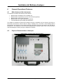
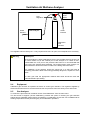
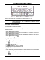
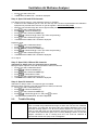
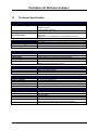
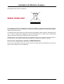
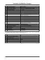
VAM01
Ventilation Air Methane
Analyser
Operating Manual
Geotechnical Instruments (UK) Ltd
Sovereign House
Queensway
Leamington Spa
Warwickshire
CV31 3JR
England
Tel:
+44 (0)1926 338111
Fax:
+44 (0)1926 338110
Email:
[email protected]
www.geotech.co.uk
Copyright© 2007
VAMOM001 / Issue 01
Ventilation Air Methane Analyser
TABLE OF CONTENTS
1
Safety Related Information ...................................................................................3
2
Introduction............................................................................................................4
3
Included in the Box ...............................................................................................4
4
General Operational Features ..............................................................................5
4.1
4.2
4.3
4.4
4.5
4.6
4.7
4.8
4.9
4.10
4.11
4.12
4.13
5
Main features of the Instrument ................................................................................................... 5
Physical Characteristics of Analyser ............................................................................................ 5
Positioning of the analyser ........................................................................................................... 6
Particle filters................................................................................................................................ 6
Access to controls ........................................................................................................................ 6
Sample gas inlet........................................................................................................................... 6
Purge air inlet ............................................................................................................................... 6
Anemometer (optional)................................................................................................................. 7
Temperature probe (optional) ...................................................................................................... 7
Power supply ............................................................................................................................ 7
Memory..................................................................................................................................... 8
Switching the Analyser On and Off........................................................................................... 8
Power-on Self Test ................................................................................................................... 8
Main Analyser Menu ..............................................................................................9
5.1
5.2
5.3
5.4
5.5
5.6
5.7
6
Main Menu.................................................................................................................................... 9
Field Calibration ........................................................................................................................... 9
Set Time/Date .............................................................................................................................. 9
Check/Clear Reading Memory ..................................................................................................... 9
Adjust Contrast............................................................................................................................. 9
Modem Diagnostics...................................................................................................................... 9
Information Screen..................................................................................................................... 10
Main read screen .................................................................................................11
6.1
7
Preliminary Checks .................................................................................................................... 11
Data Logging........................................................................................................12
7.1
7.2
7.3
8
Logging Sequence ..................................................................................................................... 12
SMS Notification......................................................................................................................... 12
Errors and warnings ................................................................................................................... 13
Modem Operation ................................................................................................14
8.1
8.2
8.3
9
Compatibility............................................................................................................................... 14
Installing the SIM Card ............................................................................................................... 14
Replacing the Modem ................................................................................................................ 14
Calibration............................................................................................................15
9.1
9.2
9.3
9.4
9.5
9.6
9.7
9.8
10
10.1
10.2
10.3
10.4
Introduction................................................................................................................................. 15
Calibration Gases....................................................................................................................... 15
Set-Up ........................................................................................................................................ 15
Equipment .................................................................................................................................. 16
Gas Analyser.............................................................................................................................. 16
Trouble Shooting ........................................................................................................................ 18
Factory Settings ......................................................................................................................... 19
Viewing Time of Last Field Calibration....................................................................................... 19
Communications Software ..............................................................................20
Introduction............................................................................................................................. 20
Installing the software............................................................................................................. 20
Starting the Application........................................................................................................... 20
Connecting to the Analyser..................................................................................................... 21
VAMOM001 Issue 01
Geotechnical Instruments (UK) Ltd
Page 1
Ventilation Air Methane Analyser
10.5
10.6
10.7
10.8
11
11.1
11.2
Downloading Data .................................................................................................................. 21
Setting the Clock .................................................................................................................... 21
Clearing data from the analyser ............................................................................................. 21
Restarting the Analyser via SMS ............................................................................................ 22
Service...............................................................................................................23
Main VAM analyser................................................................................................................. 23
Filters ...................................................................................................................................... 23
12
Technical Specification....................................................................................24
13
Appendix A – Event Log...................................................................................26
14
Appendix B – Errors and Warnings ................................................................28
14.1
Page 2
Cold Start................................................................................................................................ 28
Geotechnical Instruments (UK) Ltd
VAMOM001 Issue 01
Ventilation Air Methane Analyser
1
Safety Related Information
Information in this manual that may affect the safety of users and others is preceded by the following
symbol:
Warning.
Failure to follow this information may result in physical injury which in some cases could be fatal.
VAMOM001 Issue 01
Geotechnical Instruments (UK) Ltd
Page 3
Ventilation Air Methane Analyser
2
Introduction
This manual explains how to use the VAM01 Ventilation Air Methane Analyser.
The ventilation Air Methane Analyser is designed to monitor the methane concentration in ventilation
air from operational coal mines. It will measure the methane concentration as well as the temperature
of the air and the air flow.
All data is recorded and can be downloaded remotely via a modem.
The VAM01 is housed in a suitcase size case so that it can be easily transported to different sites. It is
intended to be used as a temporary installation.
The analyser can be operated from a mains supply or a set of batteries.
3
Included in the Box
The following items are included as standard with your VAM01 Ventilation Air Methane Analyser.
VAM01 – Analyser
VAMPSU – Mains to 12V converter
12V battery lead
GSM Aerial
Anemometer (includes 5 metre lead)
Temperature Probe (includes 5 metre lead)
CD-ROM - VAM Communicator – PC download software
USB lead
User Manual
Spare 50 µm particle filters
Spare 5 µm particle filters
QRC connectors x 3
The following optional accessories are available from Geotechnical Instruments (UK) Ltd.
•
•
•
•
•
•
Page 4
Additional user licences for VAM Communicator software
Calibration kit
Spare particle filters
Spare sample tubing
Spare QRC connectors
Service contract
Geotechnical Instruments (UK) Ltd
VAMOM001 Issue 01
Ventilation Air Methane Analyser
4
General Operational Features
4.1
Main features of the Instrument
The instrument includes the following main features:
•
•
•
•
•
Measurement of Methane in the ventilation air
Measurement of gas flow by use of an anemometer (optional)
Measurement of barometric pressure
Measurement of the gas temperature (optional)
Local and Remote (via modem) data download
The VAM01 is intended to measure the methane content of ventilation air from working coal mines. It
will monitor the methane content of the air, taking a reading every 15 minutes. These readings will be
stored within the instrument. Also stored will be the barometric pressure, the total air flow and the air
temperature. The readings can be accessed by dialling up the integral modem from a remote location
and downloading the data by using the supplied PC software.
4.2
Physical Characteristics of Analyser
VAM Analyser – showing control panel and filters
VAMOM001 Issue 01
Geotechnical Instruments (UK) Ltd
Page 5
Ventilation Air Methane Analyser
VAM Analyser - Outside
4.3
Positioning of the analyser
The analyser is contained in a sealed case and is relatively weather proof. However, it is
recommended that the analyser is not exposed to extremes of weather and is shielded from direct
sunlight and rain or snow.
4.4
Particle filters
The analyser is fitted with two user changeable particle filters. These should be changed regularly as
blocked filters can cause the sample pump to stop working.
Important
4.5
The instrument should never be operated without these filters in place. Doing so
may damage the analyser’s sensitive Infra-red bench and will invalidate your
guarantee.
Access to controls
The analyser is housed in a rugged Pelican case. It is intended that the analyser is normally operated
with the case closed. For setting up and maintenance the analyser can be operated with the case
open.
4.6
Sample gas inlet
Connect the supply of sample gas to the “Sample In” quick release connector(QRC).
4.7
Purge air inlet
The unit is purged with fresh air prior to each reading via this connector. This will be done automatically
during the logging process. The instrument will switch between sample gas and purge air at the
appropriate time.
Important
Page 6
It is important that the purge air is free from all traces of methane as the
instrument automatically zeroes the CH4 channel before each reading.
Geotechnical Instruments (UK) Ltd
VAMOM001 Issue 01
Ventilation Air Methane Analyser
4.8
Anemometer (optional)
The analyser can be configured to display and record a flow reading using an optional anemometer.
When an anemometer is fitted to the correct port, the flow (m/s) will be displayed on the main reading
screen and recorded every 15 minutes. If your analyser has been configured for anemometer readings
and an anemometer is not fitted a warning will be displayed.
The anemometer can be zeroed via the field calibration menu. With the
anemometer attached, select the calibration menu followed by the zero channels
option. Then ensuring you there is no flow across the anemometer, then select
zero anemometer to zero any offsets.
Note
4.9
Temperature probe (optional)
The analyser can be configured to display and record the sample temperature via an optional
temperature probe. When a temperature probe is fitted to the correct port, the temperature will be
displayed in the main reading screen and recorded every 15 minutes. If your analyser has been
configured for temperature probe readings and a temperature probe is not fitted a warning will be
displayed.
4.10
Power supply
The analyser requires a 12V D/C supply to operate. This will usually be supplied via the associated
custom DC power supply, but can also be supplied from a set of 12v batteries.
4.10.1
Custom DC power supply
The DC power supply is housed in a separate Pelican enclosure. The DC power supply must be
connected to a suitable mains supply (110-240V a/c). The DC power supply contains a 2.3Ah back-up
battery that will (when fully charged) maintain the operation of the analyser for approximately 5 hours
during a power cut. When mains power is restored the back-up battery will be recharged automatically.
Recharging the back-up battery can take up to 12 hours.
Note that if the power supply is to be stored for an extended period, the connector should be removed
from the battery. Otherwise the battery may discharge completely. Disconnect the power supply from
the mains, open the power supply box and remove one of the battery connectors.
Warning. Always disconnect the power supply from the mains before opening the power supply
To use the power supply again, replace the battery connector before connecting the power supply to
the mains input.
Note that there will be no output from the power supply until the mains is
connected.
Note
4.10.2
Battery power supply
It is possible to power the analyser directly from a set of 12V Lead Acid batteries. In this case use the
lead provided, making sure that the polarity is correct. Batteries should be used that are designed for
constant low current discharge. Ordinary car or traction batteries are not ideal as they are designed for
intermittent high current discharge.
VAMOM001 Issue 01
Geotechnical Instruments (UK) Ltd
Page 7
Ventilation Air Methane Analyser
4.11
Memory
The memory in the analyser is volatile, although it is retained by an internal battery back-up system.
The memory is not to be used as a permanent storage medium and any data should be transferred to
a more permanent storage medium as soon as possible using the PC software. Although unlikely,
sudden shocks, high levels of electromagnetic interference or static discharge may cause memory
corruption or loss. If this occurs the memory should be cleared and the calibration re-set using the
cold-start feature before further use.
Note
4.12
The analyser should never be stored for prolonged periods with valuable data in
memory.
Switching the Analyser On and Off
The analyser will switch on as soon as power is applied. When switching the instrument on a long beep
will be emitted. The display will show the Geotechnical Instruments (UK) Ltd logo along with the
product name. A power-on self-test will then commence.
When switching the analyser off, the on/off button must be held down for approximately 1.5 seconds.
If for any reason the analyser ‘locks-up’ and will not switch off in this manner, press and hold the on/off
button for 15 seconds; this will force the instrument to switch off. When the analyser is switched off a
clean air purge is automatically started. This ensures that the analyser is free from gas and ready for
the next measurement. This final purge is especially important if an oxygen sensor or external gas pod
if fitted, as these sensors will degrade if stored whilst contaminated with gas.
Note
4.13
Removing the power source directly may cause memory corruption. The analyser
should always be switched off using the power key, this allows the analyser to
power-down in the correct sequence.
Power-on Self Test
When switched on the analyser will perform a pre-determined self-test sequence taking approximately
40 seconds to complete. During this time a number of tests are performed to check if any operational
parameters are out of specification. See appendix B for the full list errors and their possible causes.
Any errors or warnings detected are displayed at the bottom of the screen. During this time the
analyser also checks and configures the local modem. The following information is displayed during
the self-test :•
•
•
•
•
Manufacturer’s service due date
Software version
Date format
Serial number
Baud rate
Page 8
Geotechnical Instruments (UK) Ltd
VAMOM001 Issue 01
Ventilation Air Methane Analyser
5
Main Analyser Menu
5.1
Main Menu
The menu is used to select the diagnostic, configuration and calibration options. Whilst in the main
menu data-logging is suspended until the user returns to the main read screen. The menu and submenus will automatically time-out after 5 minutes and continue logging if no key presses are detected.
The main menu is activated by pressing key
whilst the analyser is in the main read screen. A brief
warning message is displayed to remind the user that logging is suspended until the instrument has
been returned to the main read screen. The following options can be selected from the main menu
using the cursor keys:•
•
•
•
•
•
•
5.2
Field calibration
Set Time/Date
Check/Clear Memory
Adjust Contrast
Modem diagnostics
Information screen
Exit menu
Field Calibration
This option allows a user calibration to be performed on the CH4, and anemometer data channels.
Please see the section on calibration for more information.
5.3
Set Time/Date
Selected via the main menu the set time/date screen enables the user to check or set the internal
clock. Having the correct time and date is important as it is stored with every reading. The current time
and date is always displayed in the top-left corner of the main read screen. Setting the clock is a simple
process - just follow the on-screen instructions. It is also possible to switch the date format between
dd/MM/yy and MM/dd/yy formats if required.
The clock will need to be manually adjusted to cope with daylight saving changes
or changes when crossing time zones.
Note
5.4
Check/Clear Reading Memory
Clear memory screen enables the user to check how many readings have previously been taken and
clear them if necessary. Clearing readings is a simple process - just follow the on-screen instructions.
Before readings are actually deleted a caution is displayed and must be acknowledged; once readings
have been deleted they cannot be recovered.
5.5
Adjust Contrast
The VAM analyser automatically adjusts the screen contrast to maintain a normal viewing contrast
according to the display temperature. A small amount of manual adjustment is possible using the
adjust contrast option which is available via the main menu. The current setting is displayed and can
be adjusted lighter or darker using the ‘<’ and ‘>’ cursor keys. The manually adjusted setting is retained
when the read-out is switched off and therefore may require re-setting when next switched on.
5.6
Modem Diagnostics
The VAM analyser is equipped with a GSM modem for remote download of stored data. It can also be
configured to give notification of critical faults via SMS. Please see the section on Modem Operation for
information regarding configuration and set-up of the modem. The modem diagnostics screen shows
the current status of the modem. The user can refresh the status information at anytime by pressing
key ‘ Refresh’. The following status information is displayed:-
VAMOM001 Issue 01
Geotechnical Instruments (UK) Ltd
Page 9
Ventilation Air Methane Analyser
GSM: Shows network connection status, when a successful connection has been made “Registered on
home network” is shown. If a connection to a foreign network has been made then “Registered,
roaming network” is shown. In this case, higher call charges for receiving calls and sending SMS
messages are likely to be incurred. The message “Not registered, searching” indicates that the
modem is attempting to connect to a GSM network. “Not registered, not searching” indicates that the
modem has given up searching for a GSM network. Check the antenna connection or relocate the
antenna to a new location. “Registration denied” indicates that a GSM network was found but the SIM
was refused access to the network. Please contact your network provider.
Network: Shows currently selected mobile phone network, eg “O2 – UK”
Signal: Shows signal strength followed by bit error rate. 0 is a very poor signal, the maximum is 31
(good signal strength).
PIN: Shows the current network PIN number requirements. “READY” – PIN has been entered or not
required. “SIM PIN” – A PIN is required. You should disable the requirement for a PIN number prior to
fitting to modem. “SIM PUK1” – Three failed attempts were made to enter a PIN. Equipment is waiting
for a SIM PUK1 code. “SIM PUK2” – Network is waiting for an unblock code. Please contact your
Network Provider.
PIN2: (Sim Card PIN number)
From this screen the user is also able to re-initialise the modem by pressing command key ‘ Re-init’.
Re-initialising the modem clears any existing modem configuration and re-programs it with the
analyser’s default requirements. This may be necessary if the modem stops answering calls for
example. Power cycle, key ‘ ’, switches the modem OFF then ON. This may be required if the modem
has crashed i.e. stopped responding to the analyser. Step 1 turns the power off and waits 10 seconds,
the on signal is sent and it then waits 30 seconds before re-initialising the modem.
The analyser performs an automatic check of the modem and re-initialises it (if necessary) once per
day at midnight.
5.7
Information Screen
The information screen shows general information about the analyser and its configuration. The
following information is displayed:•
•
•
•
•
•
•
•
•
•
•
Page 10
Software version
Analyser serial number
Guarantee status (purchased support contract)
Logging Interval (Interval / Purge Time / Baro stabilisation time / Reading stabilisation time)
Full service due date
Date of last gas check
Date of last field calibration
Operating language
Communications settings
Number of readings taken
Time/Date format
Geotechnical Instruments (UK) Ltd
VAMOM001 Issue 01
Ventilation Air Methane Analyser
6
Main read screen
The ‘Read Gas Levels’ screen is also considered to be the normal operation screen and all operations
are carried out from this starting point. The main read screen shows the current readings, current
time/date, logging status and modem status. The current stage of the logging cycle is also displayed
including the time to the next stage. Any error messages will be displayed on the bottom-right of the
screen. Remote (or local) communications are only possible when the instrument is in this screen.
The actual data displayed on this screen will depend on the version of the analyser
and its configuration.
Note
6.1
Preliminary Checks
Prior to going to site, it is good practice to ensure:
•
•
•
•
•
•
The instruments time and date are correct.
The particle filters are clean and dry.
If required the batteries to be used have a good charge.
Ensure communications switch is towards modem to enable remote communications via modem.
The memory has sufficient space available.
Check the span calibration with a known concentration calibration-check gas.
DO’s
•
Travel to site with the instrument in the vehicle's interior - not in the boot, where it may be
subjected to extremes of temperature and possible shock damage.
•
Protect the instrument from strong direct sunlight which will quickly raise the temperature of the
instrument beyond its operating range and the LCD display will appear almost black and the
contrast setting cannot alter the contrast.
DONT’s
• Do not place the instrument against anything hot or in an unattended car during the summer as
this will cause excessive internal temperatures which may cause erroneous readings.
• Do not get the instrument wet, for example exposure to heavy rain or snow.
VAMOM001 Issue 01
Geotechnical Instruments (UK) Ltd
Page 11
Ventilation Air Methane Analyser
7
Data Logging
The primary function of the analyser is remote data-logging. The logging sequence is configured during
manufacturing and cannot be changed by the user. While powered-up the analyser will continuously
store data at 15 minute intervals following a pre-set cycle. It is capable of storing 3000 reading sets,
which corresponds to about 31 days of data.
When the memory is 95% full a warning “Memory nearly full” will be displayed by the analyser. Should
the memory become completely full the analyser will stop storing data. The warning displayed by the
analyser will change to “Logger memory full”.
7.1
Logging Sequence
The following logging sequence has been programmed into the VAM:1. Clean Air Purge.
a) Solenoid set to purge air.
b) Switch on pump.
c) Wait approx 10 minute before advancing to next stage.
2. Zero CH4 channel.
a) Zero any minor CH4 offset.
b) Stop Pump.
3. Take Barometer reading
a) Wait for reading to stabilise.
b) Record and display barometer reading.
c) Advance to next stage.
4. Sample Gases
a) Switch solenoid to sample coal mine ventilation air.
b) Start pump.
c) Wait approximately 5 minutes to ensure stable reading sample.
d) Record Methane reading.
e) Store complete reading set.
f) Stop pump.
5. Check Status
a) Send SMS message (if configured via PC software).
b) Check for errors and display any warnings.
c) Once every 24 hours power-cycle & initialise modem.
d) Begin clean air purge.
Depending on the configuration and accessories used the following data is stored for each reading :•
•
•
•
•
7.2
Current time / date
Main gas readings
Barometric pressure
Temperature
Anemometer
SMS Notification
Using the PC software supplied up to two SMS phone numbers can be specified to receive text
message notifications for memory full and flow fail indications. An SMS message will be sent to the
specified numbers when the memory is nearly full i.e will become full within 24 hours. A second SMS
message is sent when the analyser stops storing due to full memory. If no numbers have been
specified then this section is ignored.
Page 12
Geotechnical Instruments (UK) Ltd
VAMOM001 Issue 01
Ventilation Air Methane Analyser
7.3
Errors and warnings
During the logging cycle the analyser automatically checks for errors. These include checks for any
operational parameters that are out of specification. See appendix B for the full list and the possible
causes. Errors or warnings are displayed at the bottom right corner of the main read screen one at a
time. Messages are cycled automatically (every 2 seconds) 1 of 5, 2 of 5 and so on.
7.3.1
Warnings Displayed
Although not specifically identified there are two types of warning that may be displayed. Firstly there
are general warnings that may not affect the functioning of the instrument e.g. memory nearly full. In
these cases the analyser has detected a function that is outside the typical operating criteria. The
second warning type are operational parameters that could affect the performance of the analyser e.g.
CH4 channel out of calibration.
The most likely reason for the errors is either an incorrect user calibration, or sensor failure. If an
incorrect user calibration has caused the warning it should be correctable by way of returning the
instrument to factory settings, zeroing or carrying out a user calibration as necessary for the relevant
function.
If any other types of warning or error messages are displayed it is advisable to
contact Geotechnical Instruments (UK) Ltd for further information.
Note
7.3.2
Under and Over Range Codes
If a reading is under range (ie below zero) it will be displayed with ‘less than’ chevrons (<<). If a reading
is over range (ie above the maximum allowed reading) it will be displayed with ‘more than’ chevrons
(>>). These can occur if a channel has been incorrectly calibrated. A number displayed as (**)
indicates an error and a (--) indicates where no data is available.
VAMOM001 Issue 01
Geotechnical Instruments (UK) Ltd
Page 13
Ventilation Air Methane Analyser
8
Modem Operation
8.1
Compatibility
The analyser is fitted with a Siemens TC65T Quad Band GSM modem. Most GSM regions require that
a “data enabled” SIM card is fitted. Check with your Network Provider for more information. The
operator will need to supply the appropriate SIM card and operating contract.
The SIM card must be data enabled. “Data Enabled” does not refer to the ability to
send and receive SMS or MMS messages.
Note
Geotechnical Instruments (UK) Ltd or its agents are not responsible for any costs relating to
use of or connection to any GSM network with this product.
8.2
Installing the SIM Card
Power off the system or remove the power connector from the modem before changing the SIM card.
To install the SIM card firstly remove the protective cover (see diagram) by removing the six fixing
screws (requires 2.5mm Allen key). Then eject the SIM carrier using a ball point pen or similar and
remove the tray from the modem. Fit the SIM card into the carrier with the metal contacts showing, and
slide back into place.
Power up the system and modem. When the modem is searching for a GSM network the blue LED
flashes slowly (600 ms on / 600ms off). Once connection has been established, after approximately 30
seconds, the LED flashes briefly (75ms on / 3s off). After testing the modem operation using the
Modem Diagnostics option replace the modem cover.
Remember to ensure that the toggle switch is in the correct position for remote
communications.
Note
Only use 3V or 1.8V SIM cards.
Modem’s SIM tray
8.3
SIM Eject button
Replacing the Modem
The modem should only be replaced with a Siemens TC65T GSM modem. The modem must be
<CR>
configured to 38400 baud using the AT command: AT+IPR=38400
The modem should be configured by Geotechnical Instruments otherwise the remote reset via SMS
functionality will not be available.
Page 14
Geotechnical Instruments (UK) Ltd
VAMOM001 Issue 01
Ventilation Air Methane Analyser
9
Calibration
9.1
Introduction
The Ventilation Air Methane Analyser is calibrated during manufacture and when returned for service.
However, to improve accuracy between services a user calibration can be performed. This section sets
out the correct procedures to achieve an accurate user calibration. If this calibration is completed
incorrectly it may decrease the accuracy of the Gas Analyser.
Two important terms that are used within this section are “Zero” and “Span”.
Zero:
Span:
The point at which the analyser is calibrated when there is none of the target gas present.
The point at which the analyser is calibrated when a known quantity of the target gas is
present.
We recommend that the span gas has a concentration around 0.9% for optimum results. Ideally the
span calibration should be checked at monthly intervals.
9.2
Calibration Gases
User calibration of the analyser will improve the data accuracy in the range of the calibration gases
used. This may cause less accurate readings of concentrations outside this calibrated range. Users
should select the correct calibration gas for the expected gas levels on their particular application. Only
use gases with a known certified concentration.
Certified calibration gases for most gas concentrations can be supplied by
Geotechnical Instruments (UK) Ltd.
Note
Warning
9.3
For each gas used the appropriate material safety data sheet must be read and
understood before proceeding. Calibration gases can be dangerous.
Set-Up
Important
Do NOT attach the gas supply to the instrument before putting it into the “Field
Calibration Screen” by selecting the ‘FIELD CALIBRATION’ option from the main
menu.
The calibration gas supply should be connected to the normal sample inlet of the VAM analyser as
shown in the diagram.
VAMOM001 Issue 01
Geotechnical Instruments (UK) Ltd
Page 15
Ventilation Air Methane Analyser
Flow
Regulator
Outlet
Exhaust
VAM Analyser
Pressure
relief
valve
Outlet
Exhaust
Calibration
Gas
Canister
The regulator’s flow is factory set. It only requires a few turns to open, but no adjustment is necessary.
Warning
Exhaust port
When the analyser is being calibrated, there are two possible exits for the gas, via
the usual manner out of the exhaust port of the analyser or in cases of over”
pressurisation the 1/16 port on the pressure relief valve. It is recommended that
both ports have exhaust tubing attached. The exhaust tubing must emerge in a
well-vented area. Ensure there are no leaks in the tubing and connections.
The calibration of the analyser should be carried out in a safe area with all
necessary precautions taken when using potentially dangerous, explosive or toxic
gases.
For each gas used the appropriate material data sheet should be read and
understood before proceeding.
9.4
Equipment
Calibration gas mixtures as specified as above in 58 litre gas canisters. The regulator supplied by
Geotechnical Instruments is recommended as flow and pressure rates are factory set to safe levels.
9.5
Gas Analyser
To achieve the processes set out below choose “Field Calibration” from the main menu.
The first screen to appear (“Check Calibration”) provides the option of checking the gas channels
against known calibration gases before proceeding to re-calibration. Ensure the unit is stabilised at its
working temperature before performing any of the calibration operations.
Page 16
Geotechnical Instruments (UK) Ltd
VAMOM001 Issue 01
Ventilation Air Methane Analyser
Readings on the line “a” are the current readings for the channels listed. The figures displayed in line
“b” are the span targets i.e. the concentrations of the calibration gases to be used.
Note
Depending on the configuration of your analyser some gas channels may not be
active and will be shown as “N/A” or left blank. Ignore the calibration instructions
given for those channels.
Step 1: Enter Target Concentrations
DO NOT CONNECT CALIBRATION GAS YET.
Enter the certified concentrations of your calibration gases. For two-gas mixtures that contain 0.0% O2,
enter the certified O2 value at 20.9%. For three-gas mixtures with an O2 component enter the O2
certified concentration.
•
•
•
•
•
•
to Edit target concentrations.
Press
and enter the certified CH4 concentration. Then press .
Select CH4 from the menu using
Press
to Edit target concentrations.
and enter the certified CO2 concentration. Then press .
Select CO2 from the menu using
Press
to Edit target concentrations.
and enter the certified CO2 concentration or 20.9% for air
Select O2 from the menu using
calibration. Then press .
Step 2: Zero CH4 and CO2 channels
•
•
•
•
•
•
•
Press
allow the pump to run for approximately two minutes or until reading stabilises; this
purges the unit of gas.
to switch off the pump.
Press
to select “Calibration Menu”.
Press
to select “Zero Channel(s)”.
Press
to select “Zero CH4”.
Press
“USER ZERO COMPLETE.” should be displayed.
Repeat for other channels if required (except O2)
Step 3: Zero O2 channels
•
•
•
•
•
Attach the calibration equipment as pictured above with gas mixture 2 and turn on gas at regulator.
Do not run the pump.
Allow the gas to flow through the unit for approximately two minutes or until reading stabilises.
to select “Calibration Menu”.
Press
to select ”Zero Channel(s)”.
Press
to “ZERO O2”.
Scroll
VAMOM001 Issue 01
Geotechnical Instruments (UK) Ltd
Page 17
Ventilation Air Methane Analyser
•
•
Press
to select “Zero O2”.
“USER ZERO COMPLETE.” should be displayed.
Step 4: Span CH4 and CO2 channels
Use Step 5 instead, when a 3 gas calibration mixture is available.
• Continue to flow calibration gas or if the zero O2 step has not been required attach the calibration
equipment as pictured above and turn on gas at regulator. Do not run the pump.
• Allow the gas to flow through the unit for approximately two minutes or until reading stabilises.
to select “Calibration Menu”.
• Press
to “SPAN CHANNEL(S)”.
• Scroll
to select “SPAN CHANNEL(S)”.
• Press
to “SPAN CH4 @ 0.90%” (the value set previously).
• Scroll
to select “SPAN CH4 @ 0.90%”
• Press
• “CALIBRATION COMPLETE” should be displayed.
Repeat for CO2:
to select “Calibration Menu”.
• Press
to “SPAN CHANNEL(S)”.
• Scroll
to select “SPAN CHANNEL(S)”.
• Press
to “SPAN CO2 @ 0.10%” (the value set previously).
• Scroll
to select “SPAN CO2 @ 0.10%”
• Press
• “CALIBRATION COMPLETE” should be displayed.
Go to step 6.
Step 5: Span CH4, CO2 and O2 channels
Alternative to Step 4 when a 3 component gas is available
Multi-gas option requires a mix with components of CH4,CO2 and O2
to select “Calibration Menu”.
• Press
to “SPAN CHANNEL(S)”.
• Scroll
to select “SPAN CHANNEL(S)”.
• Press
to “SPAN MULTI-GAS”
• Scroll
to select “SPAN CO2 @ 0.10%”
• Press
• “CALIBRATION COMPLETE” should be displayed.
Step 6: Span O2 channels
Alternative to Step 4 when a 3 component gas is available
Multi-gas option requires a mix with components of CH4,CO2 and O2,
to select “Calibration Menu”.
• Press
to “SPAN CHANNEL(S)”.
• Scroll
to select “SPAN CHANNEL(S)”.
• Press
to “SPAN O2 @ 20.9%” and press
to select.
• Scroll
•
“CALIBRATION COMPLETE” should be displayed.
9.6
Trouble Shooting
Error message
“User Zero failed”
Page 18
Remedy
A possible reason for this is because the instrument is trying to zero to a level
which is outside the pre-determined range set when the unit was first calibrated
at the factory. To rectify this, first ensure the unit contains absolutely none of the
gas which is being zeroed. For all but O2 (which requires O2 free gas) run the
pump to purge with fresh air and repeat the zeroing process. If it will not zero,
then refer to the instructions given in the ‘Factory Settings’ section. If the Gas
Analyser continues to fail in zeroing then the unit must be returned to
Geotechnical Instruments (UK) Ltd for investigation.
Geotechnical Instruments (UK) Ltd
VAMOM001 Issue 01
Ventilation Air Methane Analyser
“Calibration failed”
9.7
Check the span is set to the correct value, if not, correct and retry spanning the
channel. Repeat the entire procedure, including zeroing the channel and then
calibrate the span. Ensure the reading is stable before spanning the channel.
This message may also appear if attempting to use the ‘Span Multi Gas’ option
when not using a gas containing concentrations of CH4, CO2 and O2.
Factory Settings
This option will reset the instrument to all of its factory programmed characteristics and will clear ALL
the user defined calibration points.
If in any doubt contact Geotechnical Instruments (UK) Ltd.
From the main “CHECK CALIBRATION” screen:
• Press
to enter the calibration menu.
to “FACTORY SETTINGS”.
• Scroll
to Select “FACTORY SETTINGS”.
• Press
• Two messages will follow, “Resetting, please wait...” and “Factory settings restored.”
9.8
Viewing Time of Last Field Calibration
Select Field Calibration from the main menu and choose ‘Last Field Cal’d’ from the Calibration menu.
This option will display the time and date that the last field calibration was performed. This date is also
shown in the instrument information screen.
VAMOM001 Issue 01
Geotechnical Instruments (UK) Ltd
Page 19
Ventilation Air Methane Analyser
10
Communications Software
10.1
Introduction
The Ventilation Air Methane analyser is provided with PC software to allow readings stored in the
analyser to be downloaded, and to perform administration of the analyser. Connection can be via
modem or directly via the serial cable provided.
The analyser is fitted with a Siemens TC65T Quad-band GSM modem. A modem for the PC is not
provided.
The software is in English only and is designed for Microsoft Windows 2000, XP or Vista.
10.2
Installing the software
Administrative privileges are required to install the software. The Microsoft .Net Framework V2 must be
installed. This software is available on the CD. Insert the CD into your computer and the installation
software should start automatically. If this feature has been disabled, start Windows Explorer and
double click “VAMCommunicatorInstaller.msi” in the root folder of the CD.
If you are using the supplied USB communications lead you will also need to install the device drivers
which can be found in the “USB Drivers” folders of the CD. There are separate drivers for 32-bit and
64-bit versions of the Microsoft Windows operating systems.
10.3
Starting the Application
Click the Start menu, select Programs (XP only), then Geotechnical Instruments and “VAM
Communicator”.
Note
Page 20
Some modems must be switched on and connected to the PC when the computer
is started for them to be listed in the drop-down list of modems. If your modem is
not listed, please check it is connected and switched on and restart your
computer.
Geotechnical Instruments (UK) Ltd
VAMOM001 Issue 01
Ventilation Air Methane Analyser
10.4
Connecting to the Analyser
10.4.1
Directly via Serial Cable
If you are using a USB serial cable, please connect it before starting the application. Click the “Direct”
button and choose the serial port from the drop down list of COM ports. On the analyser switch the
toggle switch towards “RS232”.
To begin scanning for an instrument click “Connect”. The status window shows the progress of the
connection. When an analyser has been found the Status window shows the serial number and
analyser status. The Operations buttons are enabled.
Important
10.4.2
Do not forget to put the toggle switch back to “MODEM SIM CARD”. Failure to do
so will prevent remote access via modem.
Connecting via Modem
The software maintains a list of systems and their phone numbers. Click “Via modem” to access the
modem options. The remote system’s phone number may be entered directly into Remote system
drop-down list or you can add and save it for later use by clicking Edit.
In the System Phone Numbers list enter the name of the system in the Name column and the remote
analyser’s phone number in the Number column. Click OK to save changes. The newly added name
and numbers are now added to the drop-down list of remote systems. Select the correct modem from
the list and click Connect.
The software attempts to dial the remote system, the progress of the connection is shown in the main
status window. When a connection has been made the analyser’s status is updated and the
Operations buttons are enabled. To cancel the dial-up click Cancel (below Via Modem).
10.5
Downloading Data
Click the “Download Readings” button. A progress bar shows the progress. At the end of the download
a Save As window is shown. You can either change the filename or use the default, which is based on
the VAM serial number and most recent reading time & date. When the file has been saved it will be
opened automatically in Notepad or Excel (if installed). Readings are saved in CSV file format. Once
the readings have been successfully downloaded it is a good idea to clear the analyser’s memory to
avoid duplicating readings. See the section on clearing data for details.
Logging is suspended during the download of readings.
Downloading 3000 readings over a GSM connection takes approximately 53 minutes.
10.6
Setting the Clock
The analyser’s clock can be programmed from the PC. It is best to download readings and clear the
analyser’s memory before setting the clock. The clock in the analyser can easily be set to the local time
or UTC (GMT). The advantage of using UTC is that the time will be same where-ever the analyser has
been configured in the world. Any time/date can also be entered if desired.
10.7
Clearing data from the analyser
To clear all the readings from the analyser click “Clear Memory”. A brief warning must be
acknowledged as deleted readings are not recoverable.
VAMOM001 Issue 01
Geotechnical Instruments (UK) Ltd
Page 21
Ventilation Air Methane Analyser
10.8
Restarting the Analyser via SMS
This option causes the remote modem to attempt to restart the analyser. It should only be used as a
last resort when the analyser cannot be successfully dialled and when no local access to the system is
possible. The PC must be fitted with a GSM modem. Select the GSM modem from the down list and
select or enter the remote system to be reset.
The software sends an SMS message to the remote system. When the remote modem receives the
message it will cycle the power of the analyser. The message may take up to 1 hour to be processed.
Page 22
Geotechnical Instruments (UK) Ltd
VAMOM001 Issue 01
Ventilation Air Methane Analyser
11
Service
11.1
Main VAM analyser
Your VAM analyser should be regularly serviced to ensure correct and accurate operation.
Geotechnical Instruments recommends a service and recalibration every 6 months.
11.2
Filters
The inlet sample gas and the purge air passes through two filters before reaching the analyser. These
filters may become clogged with dust. The lifetime of the filters will depend on the amount of dust
within the sample air.
The filters should be regularly inspected and changed if there is any sign of significant dirt build up.
There are two filters on each sample line, one 50 µm and one 5 µm. It is important that the filters are
replaced with equivalent filters. It is also important that the sample passes through the 50 µm filter first.
Make sure that the filters are installed in the correct orientation.
11.2.1
User serviceable parts
There are no user serviceable parts inside the analyser. Please do not attempt repair as this may
invalidate any warranty supplied with your instrument.
The following parts are supplied by Geotechnical Instruments and can be user serviced:
Particulate filters
These filters should be replaced if they are contaminated. Never operate
the instrument without the particulate filters.
Sample tubing
Always ensure that sample tubes are not contaminated or damaged.
QRC connectors
Periodically check that the O-rings on the QRC gas connectors are not
damaged. A damaged O-ring can let air into the sample gas and result in
incorrect readings. If the O-ring is damaged the complete QRC
connector should be replaced.
VAMOM001 Issue 01
Geotechnical Instruments (UK) Ltd
Page 23
Ventilation Air Methane Analyser
12
Technical Specification
POWER
Power requirements
Separate power supply
Memory backup battery
Battery specification for battery
powered systems
RANGE AND ACCURACY
Range CH4
Typical accuracy CH4
90
Response time, T
FACILITIES
Temperature measurement
Temperature accuracy
Data storage
Event storage
Communications
10 – 14 V DC, Typically 360mA
Input: 110 -220V ac,
Output: 12V DC
2.3A Hr battery back up
Lithium Manganese for data retention.
12 V lead acid battery suitable for continuous low current
discharge
Approx 2.5 hours operation per AHr of battery capacity
0 – 1.5%
+/- 0.03% vol
20 seconds
With optional probe -10°C to +75°C
±0.2ºC (± probe accuracy)
3000 readings (31 days at 15 minute intervals)
1000 events
RS232 protocol via download lead with variable baud rate
Modem link for remote data access
PUMP
Flow
Flow with 200mbar vacuum
Vacuum pull
300cc/min typically
250cc/min approximately
400mbar approximately
ENVIRONMENTAL CONDITIONS
Operating temperature range
Relative humidity
Case seal
Barometric pressure
Barometric pressure accuracy
0°C - 40°C
0 - 95% non condensing
IP65
±200mbar from calibration pressure
±5mbar typically
PHYSICAL
Weight (Main unit)
Size (Main unit)
Case material
Keys
Display
Gas sample filters
Page 24
9.5 Kg
L 530 mm, W 440 mm, D 220 mm
Polypropylene
Membrane panel
Liquid crystal display, 40 x 16 characters
Fibre optic woven back-light for low light conditions
User replaceable two stage filters on sample and purge air inlets
Geotechnical Instruments (UK) Ltd
VAMOM001 Issue 01
Ventilation Air Methane Analyser
An important notice to all our customers
WEEE COMPLIANT
The wheelie bin symbol now displayed on equipment supplied by Geotechnical Instruments signifies
that the apparatus must not be disposed of through the normal municipal waste stream but through a
registered recycling scheme.
The Waste Electrical and Electronic Equipment directive (WEEE) makes producers responsible from
st
July 1 2007 in meeting their obligations, with the fundamental aim of reducing the environmental
impact of electrical and electronic equipment at the end of its life.
Geotechnical is now registered with the Environmental Agency as a producer and has joined a
recycling scheme provider who will manage and report on our electrical waste on our behalf.
Our Producer Registration Number is WEE/GB0052TQ
So when your instrument is at the end of its life, contact our Sales team who will advise you on the next
step in order to help us meet our obligations.
VAMOM001 Issue 01
Geotechnical Instruments (UK) Ltd
Page 25
Ventilation Air Methane Analyser
13
Appendix A – Event Log
The VAM analyser incorporates the facility for a log of events. This can be used as an aid to monitoring
the use of the analyser including any user calibrations. It can also be used as a diagnostic tool if there
is a problem with the analyser. The event log can be viewed via the PC based VAM communications
software. It cannot be viewed on the analyser screen. Applicable events are stored in the event log
automatically along with a time/date stamp. No user intervention is required.
The log can hold up to 1000 separate events. If the log becomes nearly full a warning will be given on
the start up screen. If the log becomes full then no further events will be stored. The log can be
downloaded, viewed, and cleared by using the VAM communications software. The log is also cleared
when the analyser is cold started. The table below lists all of the events stored in the event log.
The event log codes are used across the complete range of Geotechnical
Instruments gas analysers. Therefore not all events listed will be applicable to
your instrument type
Note
0
1
2
3
5
6
7
8
9
10
11
12
13
14
15
16
17
18
19
20
21
22
23
24
25
26
27
28
29
30
31
32
33
34
35
Event Type
Unspecified Event
Cold Start
Manufacturers Calibration
Official Gas Check
Return to Factory settings
Successful User zero CH4
Successful User span CH4
Successful User zero CO2
Successful User span CO2
Successful User zero O2
Successful User span O2
Successful User zero CELL1
Successful User span CELL1
Successful User zero CELL2
Successful User span CELL2
Successful User zero CELL3
Successful User span CELL3
Successful User zero internal flow
Failed User zero CH4
Failed User span CH4
Failed User zero CO2
Failed User span CO2
Failed User zero O2
Failed User span O2
Failed User zero CELL1
Failed User span CELL1
Failed User zero CELL2
Failed User span CELL2
Failed User zero CELL3
Failed User span CELL3
Failed User zero internal flow
Confirm CH4 calibration
Confirm CO2 calibration
Confirm O2 calibration
Set Clock via RS232
36
Clear Memory via RS232
37
38
39
40
41
42
Downloaded readings from instrument
Upload readings to instrument
Download ID’s from instrument
Upload ID’s to instrument
Technician login
Auto-Purge
Page 26
Data Stored
0=Manual or 1=Via RS232
Needs new command
Needs new command
0=Manual or 1=Via RS232
Readings before and after
Target Value, Readings before and after
Readings before and after
Target Value, Readings before and after
Readings before and after
Target Value, Readings before and after
Readings before and after
Target Value, Readings before and after
Readings before and after
Target Value, Readings before and after
Readings before and After
Target Value, Readings before and after
Readings before and after
Reading
Target Value, Gas Reading
Reading
Target Value, Gas Reading
Reading
Target Value, Gas Reading
Reading
Target Value, Gas Reading
Reading
Target Value, Gas Reading
Reading
Target Value, Gas Reading
Reading
Target, Factory and Actual gas values
Target, Factory and Actual gas values
Target, Factory and Actual gas values
Tme before and after
Cleared
1=readings,
2=ID’s, 3=Comments,
Questions, 5=All memory and 6=Event Log.
No. of readings
No. of readings
No of ID’s
No. of ID’s
ID code
Time in seconds
Geotechnical Instruments (UK) Ltd
4=Site
VAMOM001 Issue 01
Ventilation Air Methane Analyser
43
44
45
46
47
48
49
50
51
52
53
Power-off auto-purge
Over-pressurised Warning
Keyboard locked
Mode of operation changed
Download event log
Download technician list
Upload technician list
Download phone directory
Upload phone directory
Download modem initialisation string
Upload modem initialisation string
54
Tried to store reading with memory full
55
56
57
58
59
60
61
62
Download comments
Upload comments
Download alarm levels
Upload alarm levels
Download logging parameters
Upload logging parameters
Download site questions
Upload site questions
64
Modem status reports…
70
71
72
73
74
75
76
77
Static pressure transducer zeroed
Differential pressure transducer zeroed
Update site questions
Data logging mode selected
Operate via modem selected
View data selected
Print data selected
Adjust contrast
78
Gas Alarm triggered
Time in seconds
Pressure reading
1=locked and 0=unlocked
0=Manual or 1=Via RS232 & 0=GA or 1=GEM
No. of events
No. of entries
No. of entries
No. of entries
No. of entries
0=Abort store, 1=Overwrite existing reading or 2=Unable to
overwrite existing reading
0=Not Connected, 1=Ringing, 2=Connected, 3=Busy, 4=No
Carrier, 5=No Dial tone, 6=Dialling
Reading before and after
Reading before and after
number of questions
Pump run time and logging interval
0=complete, 1=aborted and –1=comms error
Contrast offset
For the channels CH4, CO2 and O2 where 1=alarming and
0=not alarming.
The following event types are primarily instrument error or warning events. As before each event
contains the time/date and up to 12 bytes of event specific data:100
Lo-flow warning
101
102
103
104
105
106
107
108
109
Battery low warning (<20%)
Reading memory nearly full warning
Variable(s) in RAM out-of-range / corrupt
Clock invalid / corrupt
Service overdue
Secondary sensor reads error at start-up
Chemical cell reads error at start-up
Primary sensor reads error at start-up
Event log nearly full or full
VAMOM001 Issue 01
Target and actual raw flow readings
Channel
Cell type code
0=nearly full or 1=full
Geotechnical Instruments (UK) Ltd
Page 27
Ventilation Air Methane Analyser
14
Appendix B – Errors and Warnings
The table below lists the possible errors and warnings that could be displayed.
Description
Reading mem. corrupt
Memory is nearly full
Memory full
O2 bad RAM variables
ERROR – clock
corrupt
Full service overdue
Barometric transducer
??? out of cal.
Anemometer not found
Temp. probe not found
Lo-flow, check filters
Invalid logging params
14.1
Possible causes
The reading pointer is outside of the valid range (0-3000). This is probably a symptom
of a more general memory corruption. Try the download any existing readings before
cold-starting the analyser.
The analysers reading memory is over 95% full. The readings should be downloaded
and the memory cleared.
The analyser’s memory is completely full. No further readings can be stored this data
will be lost. The readings should be downloaded and the memory cleared.
Typically caused by out-of-range user calibration target variables. This is probably a
symptom of a more general memory corruption. Try the download any existing
readings before cold-starting the analyser.
The analyser’s internal clock cannot be read correctly. This is most likely a hardware
fault. Try powering the instrument off and then on.
The analyser has passed its service due date. This is programmed into the analyser
at the time of manufacture and cannot be changed by the user. Download any data
and return the analyser for service.
The analyser’s barometric transducer is reading error. This could be due to a faulty or
damaged transducer. Before returning the unit for repair check that the analysers
inlet and outlets are not blocked. Try powering the instrument off and then on.
The channel described (???) is out-of-calibration. This maybe caused by incorrect
user calibration. Try return to factory settings or a cold-start.
The analyser has been configured to take anemometer readings but it cannot access
the anemometer. Ensure the anemometer is plugged-in the correct port and is firmly
seated. It’s also worth checking that the pins in the Lemo plug and socket are not
bent or broken. Also, check the wire for damage before returning the analyser for
repair.
The analyser has been configured to take temperature readings but it cannot access
the temperature probe. Ensure the temperature probe is plugged-in the correct port
and is firmly seated. It’s also worth checking that the pins in the Lemo plug and
socket are not bent or broken. Also, check the wire for damage before returning the
analyser for repair.
The analyser has sensed a restriction when pumping in order not the damage the
analyser the pump is switched-off. Check that the particle filters are not blocked.
The pre-configured logging parameters have been set-up incorrectly or have been
corrupted. Try cold-starting the instrument.
Cold Start
A cold start should only be carried out to correct an instrument fault if no other course of action has
proved successful, as this function will clear the instrument memory entirely, reset all factory settings
and reset the internal time and date to a default setting.
To carry out a cold start, turn the analyser on and during the self-test press and continue to hold the ‘ ’
key until such time as the self-test has been completed. Upon completion of the self-test a ‘Pass-code
Entry’ screen will be displayed. At this point the ‘ ’ key may be released. Enter the code ‘12345’ and
press ‘ ’ to confirm. After the pass-code entry has been accepted the instrument’s serial number will
be displayed along with the hours of operation and three options 1-cold-start, 2-modem diagnostics
and 0-Exit. Select option ‘1’ if a cold start is to be carried out. After selection, key ‘1’ will require
pressing again to confirm the cold-start operation. After a brief confirmation message the analyser will
return to normal operation.
Important
Page 28
This function should only be used as a last resort. For gas calibration error
messages ensure a return to factory settings and user calibration has been carried
out first.
Geotechnical Instruments (UK) Ltd
VAMOM001 Issue 01