1
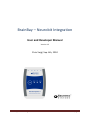
BrainBay – Neurobit Integration
User and Developer Manual
Version 1.2
Chris Veigl, Sep. 6th, 2010
BrainBay / Neurobit Integration
page 1
Table of contents
Introduction............................................................................................................................................. 3
System Requirements ......................................................................................................................... 3
User Guide ............................................................................................................................................... 4
The Neurobit Element ......................................................................................................................... 4
Changing the Device Setup.................................................................................................................. 5
Connecting with the Device and Starting/Stopping Data Acquisition................................................. 6
Using Archive Files ............................................................................................................................... 7
Adjusting other relevant BrainBay parameters ................................................................................... 7
Channel descriptions and ranges ........................................................................................................ 8
Example Configuration Setups ............................................................................................................ 9
Developer’s Guide ................................................................................................................................. 11
Development Environment ............................................................................................................... 11
Relevant Source Files......................................................................................................................... 12
Relevant Runtime files....................................................................................................................... 12
Structure of the Neurobit integration ............................................................................................... 12
Known issues ..................................................................................................................................... 14
Possible future improvements .......................................................................................................... 14
History of changes in the software ................................................................................................... 14
BrainBay / Neurobit Integration
page 2
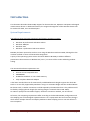
Introduction
This document describes the BrainBay support for the Neurobit Lite, Optima 2 and Optima 4 biosignal
measurement devices. In dedicated sections, the usage and integration of the Neurobit devices will
be outlined for both, users and developers.
System Requirements
The Software setup has been tested with the following operating systems:
Windows XP professional and Home edition
Windows 2000/NT
Windows Vista
Windows-7 professional and Home edition
BrainBay has been reported to work on Linux using the Windows Emulator WINE, although this has
not been verified in course of the Neurobit integration.
A query of the operating system version has been added to BrainBay to address different
presentation characteristics in Windows XP / Vista / 7 in terms of font scales and dialog window
scaling.
The minimum hardware requirements are:
Pentium-2 Intel-compatible CPU
256MB RAM
30 MB free Harddisk- or non-volatile memory
Fully compliant Bluetooth Adapter
It has been revealed that not all commercially available Bluetooth-dongles support the whole BTStack or are not fully supported by Windows. Using a no-name BT-dongle with the standard WinXP
BT-device stack, no Socket-connection could be opened by the Neurobit driver. This problem could
be fixed by changing the BT-dongle (the working dongle is a DeLock Class-1 EDR 150m).
On a Win-7 laptop with internal BT-support, the device connection worked „out-of-the-box“.
Of course, the computing requirements differ according to the desired BrainBay configuration and
the sampling rate of the biosignal acquisition device. On a Laptop with dual-core Intel CPU, designs
which utilize multiple channels and display windows at 2kHz sampling rate can run with about 7%
CPU occupation.
BrainBay / Neurobit Integration
page 3
User Guide
This section gives an overview on the provided functionality of the BrainBay biofeedback software
with special focus on the Neurobit element. To understand the wider concept of BrainBay
configurations and how to design different configurations for opto-acoustic feedback of biosignal
parameters, please refer to the BrainBay User Manual (http://brainbay.lo-res.org/ or the help pages
which are accessible in the main menu).
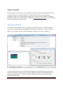
The Neurobit Element
The Interface to the Neurobit device is provided by the Signal-Source block „Neurobit Amplifier“,
which can be inserted into the existing design by selecting „Insert Element“ -> „Source“ from the
main menu. (Currently, only one „Neurobit Amplifier“ element can be active in a design.)
The new Neurobit element has set default device configuration (among other things, for Optima
devices all channels are initially inactive). By right-clicking the element in the Design window, the
element properties appear in a separate window. The Neurobit element offers the following
properties and functions:
BrainBay / Neurobit Integration
page 4
A Selection box to choose the desired device model (Lite, Optima 2 or Optima 4)
A buttons to change Neurobit device configuration (the active channels, channel functions,
captions, ranges, etc.)
Signal quality indicators for individual channels and common voltage interferences
Four buttons to play or record biosignal archives
(create a new archive, open an existing archive, close archive)
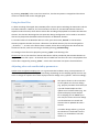
Changing the Device Setup
The hardware settings of the Neurobit device can be changed by pressing the button
„Change Device Configuration“ in the properties window of the Neurobit element: the user dialog
for channel setup is displayed and various properties can be set or modified, including:
Channel activation / deactivation
Channel label and Sensor Info
Channel profile (e.g. presets for EEG, EMG, HRV, GSR, Temperature)
User defined channel features (function, frequency characteristics, measurement range,
sampling rate)
Furthermore, some general device parameters (e.g. optional address) and quality of input
connections can be tested. Help regarding device settings is available on About tab of the device
window.
BrainBay / Neurobit Integration
page 5
The device settings are reflected in the BrainBay design in the following way:
The channel label is visible as channel caption in the Neurobit element
The channel properties (range, unit) are copied to the signal properties of the Neurobit
element’s output ports (thus, the correct units are displayed e.g. in the Oscilloscope)
The sampling rate of the BrainBay design is set to the maximum sampling rate of all active
channels (see main menu -> „Options“)
Device setup is stored together with BrainBay design with, using menu option „Design“ -> „Save
design“ and is restored when a design is opened with „Design“ -> „Load design“.
HINT: Neurobit device setup is stored in a separate file with main name as for corresponding
BrainBay design file (*.con) and name extension „.nb“. If you would like to copy or move a design file
*.con manually, you should also copy/move corresponding Neurobit setup file *.nb.
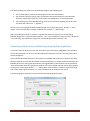
Connecting with the Device and Starting/Stopping Data Acquisition
To connect with the device and start data acquisition, press the button „Play (F7)“ in the BrainBay
control-and-status bar. At this time, the Neurobit device should be turned on and the green power
led should light up.
Given that the Bluetooth connection to the device is available and the device is ready to send data,
the data acquisition starts and the number of received samples per second can be monitored in the
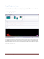
BrainBay status line. During data transmission, the signal quality of the channels can be monitored
inside the Neurobit element‘s properties window. Four colored fields indicate current signal quality,
where green means good contact, yellow means poor contact quality, red means signal overrange
and purple means signal overload. Grey color indicates that the channel is not active.
The following figure shows four connected channels with good signal quality:
BrainBay / Neurobit Integration
page 6
By pressing „Stop (F8)“ in the control-an-status bar, live data acquisition is stopped and the device
context is released and can be changed again.
Using Archive Files
To allow recording of biosignal data, BrainBay offers various options including the EDF-writer and the
File-Writer elements. However, for the convenience of the user, the Neurobit element features a
separate archive function, which allows archive file recording and playback from within the Neurobit
element. This has the advantage that one particular design configuration can be used to record live
data and to playback archived data without need for an additional element.
To record live data of the Neurobit device to a file, press the button „Record“ in the Neurobit
element properties window and enter a filename. The default directory for the recording will be
„./Archives/...“. As soon as the file has been created, all live data coming from the device will be
stored into this file, until the recording is closed by pressing „End Recording“.
An existing archive file can be played by pressing „Open“ and selecting a file.
Please note that no live data from the Neurobit device will be provided by the Neurobit element as
long as an archive file is open – all channel data is loaded from the file in this case. The playback of an
archive file is stopped by pressing „Close“ – which also reactivates live capture from the device.
Adjusting other relevant BrainBay parameters
Update rates and global sampling rate: For a given Neurobit hardware setup, some parameters of
the overall BrainBay software setup are interesting: Depending on the sampling speed, the user may
want to change the update rate of data displays and user dialogs in the „Options“ menu accordingly:
The options shown in this screenshot
set the update rate for user dialogs
(e.g. property windows of elements) to
a period of 500 samples and the
update rate for element data (e.g. FFTspectrum displays) to 50 samples.
For a sampling rate of 1000Hz (as in
this case) this means that user dialogs
are refreshed twice a second and
element data is updated 20 times a
second.
In another design where e.g. only 15
Hz GSR data is transferred from the
device, it is reasonable to set both
values to 1.
BrainBay / Neurobit Integration
page 7
Please note that refreshing element data like FFT-windows every incoming sample would cause
excessive CPU load if the device is set for a fast sampling rate of e.g. 1kHz!
Channel descriptions and ranges
By right-clicking an input- or output port of a BrainBay element, the properties of the channel
(channel description, signal range) can be adjusted. The channel description and range are displayed
e.g. in the Oscilloscope window:
Signal ranges can be copied from a selectable input port if applicable.
BrainBay / Neurobit Integration
page 8
Example Configuration Setups
Following example design configurations are provided with BrainBay along with their corresponding
Neurobit device setup files in CONFIGURATIONS\Neurobit\Tests folder:
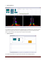
Optima4_EEG_ECG_GSR.con
This configuration features two EEG channels with 125 Hz sampling rate, one ECG/HRV channel and
one GSR channel. A FFT spectrum analysis of channel 1 is displayed, and the raw signals of both EEG
channels and the ECG channel are shown in an Oscilloscope. The GSR values are shown in a separate
Oscilloscope with slower trace.
BrainBay / Neurobit Integration
page 9
Optima4_4EEG.con
This configuration features 4 EEG channels sampling at 125 Hz. A bandpass filter in the Alpha-range is
applied to each signal and the values are averaged and displayed in a group oscilloscope window.
Below, a spectral analysis in the range of 25 Hz is shown for each channel.
Optima4_GSR.con
This simple setup provides one single channel of GSR with 15 Hz sampling frequency.
BrainBay / Neurobit Integration
page 10
Developer’s Guide
In the following sections, the development environment of the BrainBay software project and some
implementation details of the Neurobit device integration are outlined.
Development Environment
For building the executable and designing the user dialogs, Microsoft Visual Studio 2010 professional
has been used. Except the dialog-design and manipulation of the GUI resource files, all compilation
and linking can be done with the free Express version of Microsoft Visual Studio 2010.
For a list of third party libraries, please refer to the BrainBay developer guidelines.
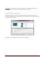
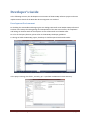
To change or build the BrainBay project, brainbay.sln shall be opened with Visual Studio:
In the project settings, the folder „neurobit_api“ is specified as additional include directory:
BrainBay / Neurobit Integration
page 11
Relevant Source Files
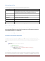
The following source files are involved in the Neurobit implementation:
Source file(s)
Description
./ob_neurobit.cpp
All user dialog interactions and processing functions of the Neurobit element
are implemented in this source file; all calls to the neurobit api / driver library
are located here, except the periodic calls of NdProtocolEngine()
./ob_neurobit.h
Header file with declaration of the optima4 object class and it’s methods
./neurobit_api/*.*
Neurobit source files for the API (currently, version 3.0.5 is used)
./brainbay.h
Enumeration of the neurobit – element type
./globals.h
Instantiation of the element (call of class constructor)
./brainbay.cpp
Processing of main menu (insert element)
./timer.cpp
Periodic call of NdProtocolEngine() if a Neurobit element is active
Relevant Runtime files
The .dll file containing the Neurobit library is expected in the subfolder „./NeurobitRuntime“ of the
binary executable (brainbay.exe). This location and the file names can be changed by modifications
of the following constants in „ob_neurobit.cpp“:
define NEUROBIT_DLL "\\NeurobitRuntime\\NeurobitDrv.DLL"
#define NEUROBIT_DIR "\\NeurobitRuntime\\"
Structure of the Neurobit integration
The implementation of the Neurobit integration is strongly oriented on the documentation of the
Neurobit API and the provided demo implementations. The initialization of the library and the device
enumeration are done in the class constructor of the element, see ob_neurobit.cpp, around line
611):
DrvLib = InitNeurobitDrvLib(DrvLibName);
if (DrvLib)
{
/* Get device list */
DevNum = NdEnumDevices(&DevTab);
if (!DevNum) {
report_error("List of supported devices is empty");
FreeLibrary(DrvLib);
}
}
One single device context handle is used. The device context is loaded from a file (either the default
file or a previously stored device context if available). For setting up or changing the device context,
BrainBay / Neurobit Integration
page 12
the integrated GUI dialog is used (see ob_neurobit.cpp, processing of the Window messages around
line 426) :
HDevWin = NdCreateDevWindow(hInst, ghWndMain, NB_DirName);
The device context is opened in the load() method of the element (when a new design configuration
is loaded) or when the GUI dialog for device context modification is opened.
To update the internal representation and the GUI after a device context has been loaded or
modified, the method
void OPTIMAOBJ::update_channelinfo(void)
is called. Here, NdGetParam(ND_PAR_CH_LABEL, i, &gv)
is used to get the number of channels, the channel name, the min and max range, the sampling rate
and the channel function (Voltage, Temperature, Conductance). The signal characteristics of the
channels and the graphical representation of the Neurobit element are updated accordingly.
Furthermore, the maximum sampling rate of all channels is calculated and the global sampling rate of
the BrainBay design is set to this value. All channels will be processed with the sampling rate of the
fastest channel.
The NdStartMeasurement(DevCtx, ND_MEASURE_NORMAL) and NdStopMeasurement(DevCtx)
functions are called in the session_start() and session_stop() methods, respectively. These
methods are called when the user starts or stops the design using F7, F8 or the corresponding
buttons in the control and status bar.
User indications are processed by the
void NdUserInd(word dc, int ind, word data)
function. Here, just the colors of the four color indicators are stored, which will be painted in the
WM_PAINT – message handler of the Neurobit properties window. Sample callbacks are processed
by the
void NdProcSamples(word dc, word phase, word sum_st, const NdPackChan *chans)
function. The signals are scaled to float values of the given channel range and stored into the
current_chn[i] array. Whenever a sample has been received,
process_packets();
is called to initiate the processing of all other exisiting elements in the design, as the Neurobit
element is considered to be the root signal source in the design. The function process_packets()
can be found in timer.cpp, where also
void CALLBACK TimerProc(UINT uID,UINT uMsg,DWORD dwUser,DWORD dw1,DWORD dw2)
is located. In this periodically called function, the Neurobit Protocol engine is called on demand:
if (GLOBAL.nb_optima4) NdProtocolEngine();
BrainBay / Neurobit Integration
page 13
Known issues
Currently only one device can be present in the design configuration
The archive file processing is not locked to the global session time
Possible future improvements
Better encapsulation of local data
Support of multiple devices and their concurrent use
Tighter integration of provided Neurobit library functions, battery and link indicator displays
Correct time-lock of the archive file to global session time
History of changes in the software
2010-07-27: added consistency check to allow just one optima 4-element at a time
2010-07-27: added missing device context creation in case no design file is loaded
2010-07-27: added grey color for deactivated channels in properties window
2010-08-12: added combo-box and functions to select device models
2010-08-12: added consistency check for GLOBAL.sessiontime in dialogs.cpp/get_sliderpos()
2010-08-12: added handling of WM_EVENT message to update GUI after closing setup window
2010-08-12: changed and added demo configurations (125 Hz for EEG channels etc.)
2010-09-06: updated information about Neurobit device configuration (now unambiguously
connected with BrainBay design).
BrainBay / Neurobit Integration
page 14