1
..
..
..
..
..
CMI
125 West Park Loop
Huntsville, AL 36806
Phone 256.722.0175
Fax 256.722.0144
Chandler/May, Inc.
.
.
VxWorks Device Driver
User’s Manual
.
.
.
.
.
.
VxWorks Device Driver Software for the
General Standards PMC-16AO-12
hosted on PowerPC and 80x86 Processors
Document number:
9005006
Revision:
1.0
Date: 09/20/99
Engineering Approval:
Date:
Quality Representative
Approval:
Date:
.
.
PMC-16AO-12 VxWorks Device Driver User’s Manual
Acknowledgments
Copyright 1999, Chandler/May, Inc. (CMI)
ALL RIGHTS RESERVED. The Purchaser of the GSC PMC-16AO-12 device driver may use or modify in
source form the subject software, but not to re-market it or distribute it to outside agencies or separate
internal company divisions. The software, however, may be embedded in their own distributed software.
In the event the Purchaser's customers require GSC PMC-16AO-12 device driver source code, then they
would have to purchase their own copy of the GSC PMC-16AO-12 device driver. CMI makes no warranty,
either expressed or implied, including, but not limited to, any implied warranties of merchantability or fitness
for a particular purpose regarding this software and makes such software available solely on an "as-is"
basis. CMI reserves the right to make changes in the GSC PMC-16AO-12 device driver design without
reservation and without notification to its users. This document may be copied for the Purchaser's own
internal use but not to re-market it or distribute it to outside agencies or separate internal company
divisions. If this document is to be copied, all copies must be of the entire document and all copyright and
trademark notifications must remain intact. The material in this document is for information only and is
subject to change without notice. While reasonable efforts have been made in the preparation of this
document to assure its accuracy, CMI assumes no liability resulting from errors or omissions in this
document, or from the use of the information contained herein.
CMI, Chandler/May, Inc. logo are trademarks of CMI.
Force is a registered trademark of Force Computers. Inc.
GSC and PMC-16AO-12 are trademarks of General Standards Corporation
Motorola and the Motorola symbol are registered trademark of Motorola, Inc.
PLX and PLX Technology are trademarks of PLX Technology, Inc.
PowerPC is a trademark of IBM Corporation.
VxWorks and Wind River Systems are registered trademarks of Wind River Systems, Inc.
September 20, 1999
1
PMC-16AO-12 VxWorks Device Driver User’s Manual
1
SCOPE......................................................................................................................................................................3
2
HARDWARE OVERVIEW....................................................................................................................................3
3
REFERENCED DOCUMENTS..............................................................................................................................3
4
MAKING THE DEVICE DRIVER .........................................................................................................................4
5
DRIVER INTERFACE............................................................................................................................................4
5.1
GS_16AO12DRVINSTALL()............................................................................................................................ 7
5.2
GS_16AO12DRVREMOVE ()............................................................................................................................ 9
5.3
OPEN()............................................................................................................................................................. 10
5.4
CLOSE () ........................................................................................................................................................... 11
5.5
WRITE() .......................................................................................................................................................... 12
5.6
IOCTL() ........................................................................................................................................................... 14
5.6.1
NO_COMMAND..................................................................................................................................17
5.6.2
INIT_BOARD........................................................................................................................................18
5.6.3
READ_REGISTER ...............................................................................................................................19
5.6.4
WRITE_REGISTER..............................................................................................................................24
5.6.5
START_DMA ........................................................................................................................................29
5.6.6
REG_FOR_INT_NOTIFY ...................................................................................................................32
5.6.7
GET_DEVICE_ERROR.......................................................................................................................34
5.6.8
WRITE_MODE_CONFIG...................................................................................................................36
5.6.9
CALIB_MODE......................................................................................................................................37
5.6.10 INT_SOURCE.......................................................................................................................................38
5.6.11 ENABLE_PCI_INTERRUPTS............................................................................................................39
5.6.12 DISABLE_PCI_INTERRUPTS...........................................................................................................40
5.6.13 PROGRAM_RATE_GEN ....................................................................................................................41
5.6.14 SELECT_ACTIVE_CHAN..................................................................................................................42
5.6.15 SET_OUT_BUFFER_SIZE.................................................................................................................43
5.6.16 GET_BUF_STATUS ............................................................................................................................45
5.6.17 ENABLE_CLK......................................................................................................................................46
5.6.18 DISABLE_CLK.....................................................................................................................................47
5.6.19 CLEAR_INT_REQUEST.....................................................................................................................48
5.6.20 GET_CALIB_STATUS.........................................................................................................................49
5.6.21 SELECT_DATA_FORMAT.................................................................................................................50
5.6.22 SELECT_SAMPLING_MODE...........................................................................................................51
5.6.23 GET_BURSTING_STATUS ................................................................................................................52
5.6.24 BURST_TRIGGER ...............................................................................................................................53
5.6.25 ENABLE_REMOTE_GND_SENSE ..................................................................................................54
5.6.26 DISABLE_REMOTE_GND_SENSE .................................................................................................55
5.6.27 SELECT_OUT_CLKING_MODE......................................................................................................56
5.6.28 SELECT_CLK_SOURCE ...................................................................................................................57
5.6.29 GET_CLK_STATUS ............................................................................................................................58
5.6.30 SINGLE_OUTPUT_CLK_EVT ..........................................................................................................59
5.6.31 SELECT_BUF_CONFIG....................................................................................................................60
5.6.32 LOAD_ACCESS_REQ ........................................................................................................................61
5.6.33 GET_CIR_BUF_STATUS ...................................................................................................................62
5.6.34 CLEAR_BUFFER ................................................................................................................................63
November 22, 2000
2
PMC-16AO-12 VxWorks Device Driver User’s Manual
1 Scope
The purpose of this document is to describe how to interface with the PMC-16AO-12
VxWorks Device Driver developed by Chandler/May, Incorporated (CMI). This software
provides the interface between "Application Software" and the 16AO-12 Board. The interface
to this board is at the I/O system level. It requires no knowledge of the actual board addressing
of control/data register locations. It does, however, require some knowledge of the individual
bit representations for most control/data registers on the device.
The 16AO-12 Driver Software executes under control of the VxWorks operating system. The
16AO-12 is implemented as a standard VxWorks device driver written in the ‘C’
programming language. The 16AO-12 Driver Software is designed to operate on CPU boards
containing MPC603, MPC604, and MPC750 processors as well as VME CPU boards
containing 80x86 processors with the same bus interface hardware as PowerPC boards. For
example, the Force PPC/PowerCore-6604 CPU board, the Motorola MVME1600,
MVME2300, MVME2400, MVME2600, and MVME2700 series boards, and the SCI JTT
686 CPU board.
2 Hardware Overview
The General Standards Corporation (GSC) 16AO-12 board is a single-width analog output
interface that fits into a PCI Mezzanine Card slot. This board provides 12 16-bit analog output
channels. The output channels are capable of supporting sequential and simultaneous updating
modes. It also provides for minimum off-line maintenance by providing calibration functions.
The 16AO-12 board includes a rate generator and a DMA controller. The rate controller is
provided to control the rate at which output channels are scanned. The DMA transfers are
supported when the board is acting as the bus master and the local bursting mode disabled.
The configuration of the interrupting capability of the 16AO-12 board is described in the
hardware manual for the board. The 16AO-12 Device Driver must be used correctly in
accordance with the hardware configuration in order to provide consistent results.
3 Referenced Documents
The following documents provided reference material used in the development of this design:
November 22, 2000
3
PMC-16AO-12 VxWorks Device Driver User’s Manual
•
PMC-16AO-12 16-Bit, 12-Channel, High Speed Analog Output PMC Board User’s
Manual – Revision A, General Standards Corporation.
•
PLX Technology, Inc. PCI 9080 PCI Bus Master Interface Chip data sheet.
•
Motorola MVME1603/1604 Single Board Computer Programmer’s Reference Guide.
•
Motorola MVME2300-Series VME Processor Module Programmer’s Reference
Guide.
•
Motorola MVME2600/2700 Single Board Computer Programmer’s Reference Guide.
•
Force PPC/PowerCore-6603/4 Technical Reference Manual.
4 Making the Device Driver
In order to use the 16AO-12 Device Driver for a particular target CPU platform, the driver
object files must be built by “making” or compiling the software modules. The object modules
are those that are loaded by the VxWorks target processor and contain functions that can then
be executed. The Wind River Tornado environment makes this process easy with one simple
command: make. make uses a file, called a makefile, which tells the development system
which source modules are to be compiled, the parameters and options to use when compiling,
and any other miscellaneous file operations a user may need to build a particular system of
object modules. The makefile included contains several Board Support Package dependent
switches that must be defined correctly for successful compilation and use. The user is only
required to set the BSP variable in the makefile. Once BSP is set correctly, the user can then
begin compiling by executing make.
The modules in the make file should begin compiling and the display should reflect a successful
compilation of all modules.
The output files from the build procedure should be:
16ao12_drv.o
Relocatable/loadable module for the device driver.
16ao12_menu.o
Relocatable/loadable module for the sample menu tool.
5 Driver Interface
The 16AO-12 Driver conforms to the device driver standards required by the VxWorks
Operating System and contains the following standard driver entry points.
November 22, 2000
4
PMC-16AO-12 VxWorks Device Driver User’s Manual
•
GS_16AO12DrvInstall() - Installs the device driver for use with multiple 16AO-12
Cards
•
GS_16AO12DrvRemove() - Removes the device driver from use
•
open() - opens a driver interface to one 16AO-12 Card
•
close() - closes a driver interface to one 16AO-12 Card
•
read() - reads data received from a 16AO-12 Card
•
write() - writes data to be transmitted by a 16AO-12 Card
•
ioctl() - performs various control and setup functions on the 16AO-12 Card
The 16AO-12 Device Driver provides a standard I/O system interface to the GSC PMC16AO-12 card for VxWorks applications that run on the VxWorks target processor. The
device driver is installed and devices created through the use of standard VxWorks I/O system
functions. The functions of the driver can then be used to access the board.
Included in the device driver software package is a menu driven board testing program and
source code. This program is delivered undocumented and unsupported but may be used to
exercise the 16AO-12 card and device driver. It can also be used to break the learning curve
somewhat for programming the 16AO-12 device.
If the user wishes to use the 16AO-12 Device Driver with the interrupting capability of the
board, then a user supplied Interrupt Service Routine (ISR) must be written. The driver will call
this ISR when an interrupt is received from the board. There are limitations on the functionality
of a VxWorks ISR. These are documented in the VxWorks Programmer’s Guide and must be
strictly followed in writing the ISR.
The Device Driver initializes the board to disable all types of 16AO-12 interrupts through
software control except for PCI interrupts controlled through the Shared Runtime - Interrupt
Control/Status register. 16AO-12 Interrupts must be enabled through the use of the ioctl
function in order to take advantage of the interrupting capability of the board. The ioctl function
must also be used to specify the user supplied ISR which will be invoked when an interrupt is
received from the board. If interrupting is enabled and the user supplied ISR has not been
specified then nothing will happen in the driver when an interrupt is received from the board.
The 16AO-12 Device Driver allows for multiple boards on a single PCI bus. Each board will
be addressed as a separate VxWorks I/O system device. This device will be created when the
driver is installed and is then available for all driver operations (open, close,...).
It is important to note that the 16AO-12 device driver is target processor dependent and thus
BSP dependent. System calls are made within the driver that are only available through certain
board support packages. This is due to the fact that PCI memory and I/O space could be
November 22, 2000
5
PMC-16AO-12 VxWorks Device Driver User’s Manual
mapped differently for each target processor board. Also, it may be possible that the PMC slot
interrupt level may be mapped differently for each target processor board.
November 22, 2000
6
PMC-16AO-12 VxWorks Device Driver User’s Manual
5.1
GS_16AO12DrvInstall()
The GS_16AO12DrvInstall () function installs the device driver into the VxWorks operating
system. This function must be called prior to using any of the other driver functions. This
function should not be called again without first calling the GS_16AO12DrvRemove() function.
The GS_16AO12DrvInstall () function performs the following operations:
•
Installs the device driver into the VxWorks operating system
•
Performs the following for each PMC Slot on the processor board
•
Determines if this slot contains a PCI card by examining the CPU board’s registers
•
Determines if the slot contains a 16AO-12 board by examining the PCI
Configuration Device Type and Vendor ID Registers
•
Programs the PCI Configuration Base Address and Configuration Address
Registers with predefined addresses
•
Enables the 16AO-12 Card to respond over the PCI Bus
•
Connects the driver interrupt handler for the interrupt number
•
Installs a device for the PMC Slot
•
Enables the PCI Interrupt for the PMC Slot
PROTOTYPE:
extern int GS_16AO12DrvInstall(BOOL bDebug);
Where:
bDebug - A boolean that is sent to the driver to enable debugging. If enabled the driver will
display error and status messages on the console during driver access. Note: this
should not be enabled during time sensitive processes.
Returns OK on success and ERROR on failure
November 22, 2000
7
PMC-16AO-12 VxWorks Device Driver User’s Manual
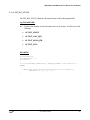
EXAMPLE:
STATUS iStatus;
/* Install the 16AO-12 VxWorks Device Driver. */
iStatus = GS_16AO12DrvInstall(TRUE);
November 22, 2000
8
PMC-16AO-12 VxWorks Device Driver User’s Manual
5.2
GS_16AO12DrvRemove()
The GS_16AO12DrvRemove() function is used to remove the 16AO-12 Device Driver from
the VxWorks operating system. This function should only be called after a call to the
GS_16AO12DrvInstall() function. The GS_16AO12DrvRemove() function closes all the
open devices for each PMC slot and removes the device driver from the operating system.
PROTOTYPE:
extern int GS_16AO12DrvRemove(void);
Returns OK on success and ERROR on failure
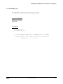
EXAMPLE:
STATUS iStatus;
/* Remove the 16AO-12 Driver */
iStatus = GS_16AO12DrvRemove();
November 22, 2000
9
PMC-16AO-12 VxWorks Device Driver User’s Manual
5.3
open()
The open() function is the standard VxWorks entry point to open a connection to a 16AO-12
Card in one PMC Slot. This function may only be called after a call to the
GS_16AO12DrvInstall() function is made. Each PMC device can be opened in analog mode,
digital mode, or both analog and digital modes. In other words, a user can associate two file
descriptors with one device. One file descriptor can represent the analog portion of the
16AO-12 and the other can represent the digital portion of the 16AO-12 device.
PROTOTYPE:
extern int open(const char *cName, int iFlags, int iMode)
Where:
cName -
name of the device being opened, which is one of the following depending on the
slot the 16AO-12 Board is in:
•
GS_16AO12_PMC1 - PMC slot 1
•
GS_16AO12_PMC2 - PMC slot 2
iFlags -
is not used.
iMode -
is not used.
Returns OK on success and ERROR on failure
EXAMPLE:
int
LOCAL char
int
FileDesc[2];
*devName[] = { GS_16AO12_PMC1, GS_16AO12_PMC2 };
16AO12Slot = 1;
/*
open the 16AO-12 device for slot 1
*/
FileDesc[16AO12Slot] = open(devName[16AO12Slot], O_RDWR, 0644);
if (FileDesc[16AO12Slot] == ERROR)
{
logMsg("Cannot Open Device Error %s\n\n",
(int) devName[16AO12Slot], 0, 0, 0, 0, 0);
}
November 22, 2000
10
PMC-16AO-12 VxWorks Device Driver User’s Manual
5.4
close()
The close() function is the standard VxWorks entry point to close a connection to a 16AO-12
Card in one PMC Slot. This function should only be called after the open function has been
successfully called for a slot where a 16AO-12 Card resides. The close function closes the
interface to a 16AO-12 device.
PROTOTYPE:
extern STATUS close(int iFd);
Where:
iFd -
File Descriptor returned from a call to the open function.
Returns OK if successful or ERROR if unsuccessful.
EXAMPLE:
int FileDesc[2];
int 16AO12Slot = 1;
/*
if
{
close the device on slot 2 */
(close(FileDesc[16AO12Slot]) == ERROR)
logMsg("Close Error for Slot #%d\n\n", 16AO12Slot, 0, 0, 0, 0, 0);
}
FileDesc[16AO12Slot] = ERROR;
November 22, 2000
11
PMC-16AO-12 VxWorks Device Driver User’s Manual
5.5
write()
The write() function is the standard VxWorks entry point to transmit channel data to the
16AO-12 Card FIFO in one PMC Slot. This function should only be called after the open
function has been successfully called for a slot where a 16AO-12 Card resides.
The data written to the FIFO will either be transferred to the user buffer using the PLX 9080
DMA capability or will be accessed directly and assigned 16 bits (bits 0…15) at a time,
depending on the write mode of the driver that is set through an ioctl() function. It is necessary
to set the active output channels. Once the channels are selected, the data will be written in
ascending order of the selected channels in the channel group. The last active channel in the
channel group is tagged with the end-of-frame flag. This allows the buffer to know when the
last value has been reached. The end-of-frame flag is bit 16 in the data buffer. It should be
noted that it is the user’s responsibility to assure that enough data is supplied to fill the
requested channels. The data written to the output buffer must be flushed to the output channel
specified by the user when the DMA transfer functionality is being used. Thus, triggered burst is
necessary. This is done to give the user flexibility for writing one or many channels at a time.
There are two configurations the output buffer can have, open and circular. The open buffer is
self-flushing and does not require the user to issue a burst. The circular buffer, or closed
buffer, holds output data indefinitely. The data frame circulates through the buffer while passing
data values to the active channels.
PROTOTYPE:
extern int write(int iFd, char *cBuffer, size_t iNBytes);
Where:
iFd
-
cBuffer -
File Descriptor returned from a call to the open function.
pointer to array of data to write.
iNBytes - total number of bytes to write.
Returns Number of bytes written if successful or ERROR if unsuccessful.
November 22, 2000
12
PMC-16AO-12 VxWorks Device Driver User’s Manual
EXAMPLE:
#define MAXSAMPLES 32
int
int
char
FileDesc;
i, iNumBytesWritten;
pusBuffer[MAXSAMPLES * 2];
/* Configure driver mode */
if( ioctl(FileDesc[16AO12Slot], WRITE_MODE_CONFIG, DMA_MODE) == ERROR )
{
logMsg("ioctl WRITE_MODE_CINFIG Failed for Slot #%d\n\n",
16AO12Slot, 0, 0, 0, 0, 0);
}
iNumBytesWritten = write(FileDesc[16AO12Slot],
pusBuffer,
sizeof(pusBuffer));
if (iNumBytesWritten == 0)
{
logMsg("Write failed for Slot #%d\n", 16AO12Slot, 0, 0, 0, 0, 0);
}
November 22, 2000
13
PMC-16AO-12 VxWorks Device Driver User’s Manual
5.6
ioctl()
The ioctl() function is the standard VxWorks entry point to perform control and setup
operations on a 16AO-12 Card in one PMC Slot. This function should only be called after the
open function has been successfully called for a slot where a 16AO-12 Card resides. The
ioctl() function will perform different functions based upon the function parameter. These
functions will be described in the following subparagraphs.
PROTOTYPE:
extern int ioctl(int iFd, int iFunction, int iArg);
Where:
iFd - File Descriptor returned from a call to the open function.
iFunction - The ioctl function to perform which is one of the following:
NO_COMMAND - Empty command, performs nothing.
INIT_BOARD - Initializes the 16AO-12 board.
READ_REGISTER - Reads a specified 16AO-12 register.
WRITE_REGISTER - Writes to a specified 16AO-12 register.
START_DMA - Starts a DMA write from the 16AO-12 board
REG_FOR_INT_NOTIFY - Registers the application code to be notified when an
interrupt occurs.
GET_DEVICE_ERROR - Returns the error that occurred during the last access to the
16AO-12 driver.
WRITE_MODE_CONFIG - Configures the 16AO-12 write() mode (FIFO burst writes
or DMA enabled FIFO writes).
CALIB_MODE – Sets and runs calibration operation.
INT_SOURCE – Sets interrupt source condition.
ENABLE_PCI_INTERRUPTS – Enables PCI interrupts in order for the 16AO-12 to
produce a local interrupt request.
DISABLE_PCI_INTERRUPTS – Disables PCI Interrupts.
November 22, 2000
14
PMC-16AO-12 VxWorks Device Driver User’s Manual
PROGRAM_RATE_GEN – Programs the rate generator for specified sample rate
frequency.
SELECT_ACTIVE_ CHAN – Activates output channels.
SET_OUT_BUFFER_SIZE – Sets the virtual size of the active output buffer.
GET_ BUF_STATUS – Retrieves the output buffer status flag information.
ENABLE_CLK – Enables output clocking.
DISABLE_CLK – Disables output clocking.
CLEAR_INT_REQUEST – Clears the Interrupt Request flag.
GET_CALIB_STATUS – Retrieves the status of autocalibration.
SELECT_DATA_FORMAT – Selects offset binary or two’s compliment output data
format.
SELECT_SAMPLING_MODE – Selects continuous or triggered burst sampling mode.
GET_BURSTING_STATUS – Retrieves the status of bursting process.
BURST_TRIGGER – Initiates transfer of data from buffer to active output channels.
ENABLE_REMOTE_GND_SENSE – Allows correction for potential difference while
connected to remote ground system.
DISABLE_REMOTE_GND_SENSE – Disallows correction for potential difference
while connected to remote ground system.
SELECT_OUT_CLKING_MODE – Selects simultaneous or sequential output
clocking.
SELECT_CLK_SOURCE – Sets clocking to come from either an external source or an
internal rate generator.
GET_CLK_STATUS – Retrieves the status of the clocking.
SINGLE_OUTPUT_CLK_EVT – Produces a single clocking event.
SELECT_BUF_CONFIG – Selects a circular (closed) or open buffer configuration.
LOAD_ACCESS_REQ – Requests loading access to a circular buffer.
GET_CIR_BUF_STATUS – Retrieves status of circular buffer.
November 22, 2000
15
PMC-16AO-12 VxWorks Device Driver User’s Manual
CLEAR_BUFFER – Empties output buffer.
iArg - The parameters to the specific ioctl() function. See the following subsections for a
description of the parameters for each function.
Returns OK if successful or ERROR if unsuccessful.
November 22, 2000
16
PMC-16AO-12 VxWorks Device Driver User’s Manual
5.6.1
NO_COMMAND
This is an empty driver entry point. This command may be given to validate that the driver
is correctly installed and that the 16AO-12 board device has been successfully opened.
arg PARAMETER:
Not used.
EXAMPLE:
int FileDesc[2];
int 16IAOSlot = 1;
if (ioctl(FileDesc[16AO12Slot], NO_COMMAND, 0) == ERROR)
{
logMsg("ioctl NO_COMMAND Failed for Slot #%d\n\n", 16AO12Slot,
0, 0, 0, 0, 0);
}
November 22, 2000
17
PMC-16AO-12 VxWorks Device Driver User’s Manual
5.6.2
INIT_BOARD
The INIT_BOARD function initializes the board and sets all defaults.
arg PARAMETER:
Not used.
EXAMPLE:
int FileDesc[2];
int 16AO12Slot = 1;
if (ioctl(FileDesc[16AO12Slot], INIT_BOARD, 0) == ERROR)
{
logMsg("Board Initialization Failed for Slot #%d\n\n",
16AO12Slot,
0, 0, 0, 0, 0);
}
November 22, 2000
18
PMC-16AO-12 VxWorks Device Driver User’s Manual
5.6.3
READ_REGISTER
The READ_REGISTER function reads and returns the contents of one of the 16IAO
registers.
arg PARAMETER:
REG_PARAM *
where REG_PARAM is defined to be
typedef struct RegParam
{
int
ULONG
e16AO12Register;
*pulValue;
} REG_PARAM;
and,
int e16AO12Register - One of the following registers to read. Refer to the 16AO-12
hardware documentation for a description of each register.
*** 16AO-12 Registers ***
BOARD_CTRL_REG
CHAN_SELECTION_REG
RATE_CTRL_REG
BUFF_OPS_REG
OUTPUT_BUF_REG
*** DMA Registers ***
DMA_CH_0_MODE
DMA_CH_0_PCI_ADDR
DMA_CH_0_LOCAL_ADDR
November 22, 2000
19
PMC-16AO-12 VxWorks Device Driver User’s Manual
DMA_CH_0_TRANS_BYTE_CNT
DMA_CH_0_DESC_PTR
DMA_CH_1_MODE
DMA_CH_1_PCI_ADDR
DMA_CH_1_LOCAL_ADDR
DMA_CH_1_TRANS_BYTE_CNT
DMA_CH_1_DESC_PTR
DMA_CMD_STATUS
DMA_MODE_ARB_REG
DMA_THRESHOLD_REG
*** PCI Configuration Registers ***
DEVICE_VENDOR_ID
STATUS_COMMAND
CLASS_CODE_REVISION_ID
BIST_HDR_TYPE_LAT_CACHE_SIZE
PCI_MEM_BASE_ADDR
PCI_IO_BASE_ADDR
PCI_BASE_ADDR_0
PCI_BASE_ADDR_1
CARDBUS_CIS_PTR
SUBSYS_ID_VENDOR_ID
PCI_BASE_ADDR_LOC_ROM
LAT_GNT_INT_PIN_LINE
November 22, 2000
20
PMC-16AO-12 VxWorks Device Driver User’s Manual
*** Local Configuration Registers. ***
PCI_TO_LOC_ADDR_0_RNG
LOC_BASE_ADDR_REMAP_0
MODE_ARBITRATION
BIG_LITTLE_ENDIAN_DESC
PCI_TO_LOC_ROM_RNG
LOC_BASE_ADDR_REMAP_EXP_ROM
BUS_REG_DESC_0_FOR_PCI_LOC
DIR_MASTER_TO_PCI_RNG
LOC_ADDR_FOR_DIR_MASTER_MEM
LOC_ADDR_FOR_DIR_MASTER_IO
PCI_ADDR_REMAP_DIR_MASTER
PCI_CFG_ADDR_DIR_MASTER_IO
PCI_TO_LOC_ADDR_1_RNG
LOC_BASE_ADDR_REMAP_1
BUS_REG_DESC_1_FOR_PCI_LOC
*** Run Time Registers ***
MAILBOX_REGISTER_0
MAILBOX_REGISTER_1
MAILBOX_REGISTER_2
MAILBOX_REGISTER_3
MAILBOX_REGISTER_4
MAILBOX_REGISTER_5
MAILBOX_REGISTER_6
November 22, 2000
21
PMC-16AO-12 VxWorks Device Driver User’s Manual
MAILBOX_REGISTER_7
PCI_TO_LOC_DOORBELL
LOC_TO_PCI_DOORBELL
INT_CTRL_STATUS
PROM_CTRL_CMD_CODES_CTRL
DEVICE_ID_VENDOR_ID
REVISION_ID
MAILBOX_REG_0
MAILBOX_REG_1
*** Messaging Queue Registers ***
OUT_POST_Q_INT_STATUS
OUT_POST_Q_INT_MASK
IN_Q_PORT
OUT_Q_PORT
MSG_UNIT_CONFIG
Q_BASE_ADDR
IN_FREE_HEAD_PTR
IN_FREE_TAIL_PTR
IN_POST_HEAD_PTR
IN_POST_TAIL_PTR
OUT_FREE_HEAD_PTR
OUT_FREE_TAIL_PTR
OUT_POST_HEAD_PTR
OUT_POST_TAIL_PTR
November 22, 2000
22
PMC-16AO-12 VxWorks Device Driver User’s Manual
Q_STATUS_CTRL_REG
ULONG *pulValue - Pointer to the location where the value read is to be stored
EXAMPLE:
int
REG_PARAM
ULONG
int
FileDesc[2];
theReg;
ulValue;
16AO12Slot = 1;
theReg.pulValue = &ulValue;
theReg.e16AO12Register = BOARD_CTRL_REG;
if (ioctl(FileDesc[16AO12Slot], READ_REGISTER, (int) &theReg) ==
ERROR)
{
logMsg("Read Register Failed for Slot #%d\n\n", 16AO12Slot,
0, 0, 0, 0, 0);
}
November 22, 2000
23
PMC-16AO-12 VxWorks Device Driver User’s Manual
5.6.4
WRITE_REGISTER
The WRITE_REGISTER function writes a value to one of the 16AO-12 Registers.
arg PARAMETER:
REG_PARAM *
where REG_PARAM is defined to be
typedef struct RegParam
{
int
ULONG
e16AO12Register;
*pulValue;
} REG_PARAM;
and,
int e16AO12Register - One of the following registers to write. Refer to the 16AO-12
Hardware documentation for a description of each register.
*** 16AO12 Registers ***
BOARD_CTRL_REG
CHAN_SELECTION
RATE_CTRL_REG
BUFF_OPS_REG
OUTPUT_BUF_REG
*** DMA Registers ***
DMA_CH_0_MODE
DMA_CH_0_PCI_ADDR
DMA_CH_0_LOCAL_ADDR
November 22, 2000
24
PMC-16AO-12 VxWorks Device Driver User’s Manual
DMA_CH_0_TRANS_BYTE_CNT
DMA_CH_0_DESC_PTR
DMA_CH_1_MODE
DMA_CH_1_PCI_ADDR
DMA_CH_1_LOCAL_ADDR
DMA_CH_1_TRANS_BYTE_CNT
DMA_CH_1_DESC_PTR
DMA_CMD_STATUS
DMA_MODE_ARB_REG
DMA_THRESHOLD_REG
*** PCI Configuration Registers ***
DEVICE_VENDOR_ID
STATUS_COMMAND
CLASS_CODE_REVISION_ID
BIST_HDR_TYPE_LAT_CACHE_SIZE
PCI_MEM_BASE_ADDR
PCI_IO_BASE_ADDR
PCI_BASE_ADDR_0
PCI_BASE_ADDR_1
CARDBUS_CIS_PTR
SUBSYS_ID_VENDOR_ID
PCI_BASE_ADDR_LOC_ROM
LAT_GNT_INT_PIN_LINE
November 22, 2000
25
PMC-16AO-12 VxWorks Device Driver User’s Manual
*** Local Configuration Registers. ***
PCI_TO_LOC_ADDR_0_RNG
LOC_BASE_ADDR_REMAP_0
MODE_ARBITRATION
BIG_LITTLE_ENDIAN_DESC
PCI_TO_LOC_ROM_RNG
LOC_BASE_ADDR_REMAP_EXP_ROM
BUS_REG_DESC_0_FOR_PCI_LOC
DIR_MASTER_TO_PCI_RNG
LOC_ADDR_FOR_DIR_MASTER_MEM
LOC_ADDR_FOR_DIR_MASTER_IO
PCI_ADDR_REMAP_DIR_MASTER
PCI_CFG_ADDR_DIR_MASTER_IO
PCI_TO_LOC_ADDR_1_RNG
LOC_BASE_ADDR_REMAP_1
BUS_REG_DESC_1_FOR_PCI_LOC
*** Run Time Registers ***
MAILBOX_REGISTER_0
MAILBOX_REGISTER_1
MAILBOX_REGISTER_2
MAILBOX_REGISTER_3
MAILBOX_REGISTER_4
MAILBOX_REGISTER_5
MAILBOX_REGISTER_6
November 22, 2000
26
PMC-16AO-12 VxWorks Device Driver User’s Manual
MAILBOX_REGISTER_7
PCI_TO_LOC_DOORBELL
LOC_TO_PCI_DOORBELL
INT_CTRL_STATUS
PROM_CTRL_CMD_CODES_CTRL
DEVICE_ID_VENDOR_ID
REVISION_ID
MAILBOX_REG_0
MAILBOX_REG_1
*** Messaging Queue Registers ***
OUT_POST_Q_INT_STATUS
OUT_POST_Q_INT_MASK
IN_Q_PORT
OUT_Q_PORT
MSG_UNIT_CONFIG
Q_BASE_ADDR
IN_FREE_HEAD_PTR
IN_FREE_TAIL_PTR
IN_POST_HEAD_PTR
IN_POST_TAIL_PTR
OUT_FREE_HEAD_PTR
OUT_FREE_TAIL_PTR
OUT_POST_HEAD_PTR
OUT_POST_TAIL_PTR
November 22, 2000
27
PMC-16AO-12 VxWorks Device Driver User’s Manual
Q_STATUS_CTRL_REG
ULONG *pulValue - Pointer to the location containing the value to be written.
EXAMPLE:
int
FileDesc[2];
REG_PARAM theReg;
ULONG ulValue = 0xAAAA;
int
16AO12Slot = 1;
theReg.pulValue = &ulValue;
theReg.e16AO12Register = OUT_Q_PORT;
if (ioctl(FileDesc[16AO12Slot], WRITE_REGISTER, (int) &theReg) ==
ERROR)
{
logMsg("Write Register Failed for Slot #%d\n\n", 16AO12Slot,
0, 0, 0, 0, 0);
}
November 22, 2000
28
PMC-16AO-12 VxWorks Device Driver User’s Manual
5.6.5
START_DMA
The START_DMA function configures the 16AO-12 DMA registers for a DMA transfer
from the board, and then starts the transfer.
arg PARAMETER:
DMA_PARAM *
where DMA_PARAM is defined to be
typedef struct DMAParam
{
int
ULONG
ULONG
ULONG
ULONG
ULONG
ULONG
DMAChannel;
ulDMAMode;
ulDMALocalAddress;
ulDMAByteCount;
ulDMADescriptorPtr;
ulDMAArbitration;
ulDMAThreshold;
} DMA_PARAM;
and,
int DMAChannel - DMA channel to perform transfer on. Must be one of the following:
•
DMA_CHAN_0
•
DMA_CHAN_1
ULONG ulDMAMode - Value to be written to the 16AO-12 DMA Mode Register.
ULONG ulDMALocalAddress - Value to be written to the 16AO-12 DMA Local
Address Register. Data returned is little endian and
may need to be byte/word swapped.
ULONG ulDMAByteCount - Value to be written to the 16AO-12 DMA Byte Count
Register.
ULONG ulDMADescriptorPtr - Value to be written to the 16AO-12 DMA Descriptor
Pointer Register.
November 22, 2000
29
PMC-16AO-12 VxWorks Device Driver User’s Manual
ULONG ulDMAArbitration - Value to be written to the 16AO-12 DMA Arbitration
Register.
ULONG ulDMAThreshold - Value to be written to the 16AO-12 DMA Threshold
Register.
See the PLX-PCI PCI Bus Master Interface Data Sheet for a description of the DMA
registers.
DMA WRITE EXAMPLE:
#define
int
DMA_PARAM
ULONG
REG_PARAM
ULONG
DWORD_COUNT 80
iIndex, FileDesc[2], 16AO12Slot = 1;
DMAParameters;
pulBuffer[DWORD_COUNT];
theReg;
ulValue;
/* Setup parameters to perform a DMA Write to the analog output FIFO
buffer. */
DMAParameters.DMAChannel
DMAParameters.ulDMAMode
DMAParameters.ulDMALocalAddress
DMAParameters.ulDMAByteCount
DMAParameters.ulDMADescriptorPtr
DMAParameters.ulDMAArbitration
DMAParameters.ulDMAThreshold
=
=
=
=
=
=
=
0;
0x943;
(ULONG) pulBuffer;
DWORD_COUNT * 4;
0x2;
0;
0;
if (ioctl(FileDesc[16AO12Slot], START_DMA, (int) &DMAParameters) ==
ERROR)
{
logMsg("Start DMA Failed for Slot #%d\n\n", 16AO12Slot,
0, 0, 0, 0, 0);
}
/* Wait for the DMA to Complete. */
theReg.pulValue
= &ulValue;
theReg.e16AO12Register = DMA_CMD_STATUS;
do
{
if(ioctl(FileDesc[16AO12Slot], READ_REGISTER, (int)&theReg) ==
ERROR)
{
logMsg("Read Register Failed for Slot #%d\n\n", 16AO12Slot,
0, 0, 0, 0, 0);
break;
}
November 22, 2000
30
PMC-16AO-12 VxWorks Device Driver User’s Manual
} while (! (ulValue & 0x10));
/* Clear the DMA channel 0/1 command/status register. */
ulValue = 0;
theReg.pulValue
= &ulValue;
theReg.e16AO12Register = DMA_CMD_STATUS;
if (ioctl(FileDesc[16AO12Slot], WRITE_REGISTER, (int) &theReg) ==
ERROR)
{
logMsg("Write Register Failed\n\n",
0, 0, 0, 0, 0, 0);
}
November 22, 2000
31
PMC-16AO-12 VxWorks Device Driver User’s Manual
5.6.6
REG_FOR_INT_NOTIFY
The REG_FOR_INT_NOTIFY function will register or unregister for notification that an
interrupt has occurred on the 16AO-12 board. If this function is called with a pointer to a
subroutine, that routine will be invoked when a 16AO-12 interrupt occurs. If a function is
currently registered for interrupt notification and is called with a NULL pointer, the function
will no longer be called when an interrupt occurs. The parameter sent to the notification
routine will be the slot number of the 16AO-12 Board that has interrupted and will be one
of the following:
•
16AO12_PMC1
•
16AO12_PMC2
Note that the internal driver interrupt handler will clear interrupts after calling the user
supplied ISR.
arg PARAMETER:
int (*intHandler)(int) - Pointer to a routine to handle the interrupt notification or a NULL
pointer if the caller wants to unregister for interrupt notification.
EXAMPLE:
int FileDesc[2];
int 16AO12Slot = 1;
int intHandler(ULONG ulSlotNum)
{
REG_PARAM
theReg;
ULONG
ulValue;
/* execute interrupt control here */
return (0);
}
/* intHandler */
/* Request notification on the user selected conditions. */
if (ioctl(FileDesc[16AO12Slot], REG_FOR_INT_NOTIFY, (int)
intHandler) == ERROR)
{
November 22, 2000
32
PMC-16AO-12 VxWorks Device Driver User’s Manual
logMsg("Request Interrupt Notification Failed\n\n",0,0,0,0,0,0 );
}
November 22, 2000
33
PMC-16AO-12 VxWorks Device Driver User’s Manual
5.6.7
GET_DEVICE_ERROR
The GET_DEVICE_ERROR function will return the error that occurred on the last call to
one of the 16AO-12 Device Driver entry points. Whenever a driver function is called and
it returns an error, this function may be called to determine the cause of the error.
arg PARAMETER:
int * - Pointer to the location of where the error code is to be written. It will be one of the
following:
NO_ERR - No Error Occurred.
INVALID_PARAMETER_ERR - An Invalid Parameter was sent to driver.
RESOURCE_ERR - The driver could not obtain a resource (memory or semaphore) to
perform its function.
BOARD_ACCESS_ERR - Failure occurred when the GS_16AO12DrvInstall function
fails when probing the 16AO-12 card’s Board Status
Register.
DEVICE_ADD_ERROR - Failure occurred when the GS_16AO12DrvInstall function
fails when trying to add device to the VxWorks Operating
System.
ALREADY_OPEN_ERROR - A call to the open driver access routine for a device that
is already open.
INVALID_DRV_NUM_ERR - Returned from the GS_16AO12DrvInstall function if
an invalid driver number was obtained when trying to
add the device driver to the VxWorks operating
system. Also returned from the
GS_16AO12DrvRemove function if the driver failed to
remove the device driver from the VxWorks operating
system.
ALREADY_INSTALLED_ERR - Returned from the GS_16AO12DrvInstall function if
the driver has already been installed.
PCI_CONFIG_ERR - Returned from the GS_16AO12DrvInstall function if a read or
write of a PCI Configuration Register fails.
November 22, 2000
34
PMC-16AO-12 VxWorks Device Driver User’s Manual
INVALID_BOARD_STATUS_ERR - Returned from the GS_16AO12DrvInstall
function if an invalid board status is read from
the 16AO-12 Board.
FIFO_BUFFER_ERR - If during a write() transaction the FIFO buffer is indicated to be
empty by the status of the buffer status flags or more data is
requested than what is available, the driver will return the
number of bytes that could be written along with throwing this
error condition.
EXAMPLE:
int FileDesc[2];
int 16AO12Slot = 1;
int Status;
/* Send the Get Device Error Code Command for this channel
*/
if (ioctl(FileDesc[16AO12Slot], GET_DEVICE_ERROR, (int) &Status) ==
ERROR)
{
logMsg("Get Device Error Code Failed for Slot #%d\n\n",
16AO12Slot, 0, 0, 0, 0, 0);
}
November 22, 2000
35
PMC-16AO-12 VxWorks Device Driver User’s Manual
5.6.8
WRITE_MODE_CONFIG
The WRITE_MODE_CONFIG function will configure the driver for the type of write() to
the output FIFO to be performed. There are two types of writes. The first being referred to
as SCAN_MODE where each sample is written out to the output FIFO one at a time and
put into the user buffer given. The other type of write is referred to as DMA_MODE,
which utilizes the DMA capability of the board. This mode must be set before attempting to
write the outputs.
arg PARAMETER:
int * - Pointer to one of the following values:
•
SCAN_MODE
•
DMA_MODE
EXAMPLE:
int FileDesc[2];
int 16AO12Slot = 1;
int iMode;
iMode = DMA_MODE;
if (ioctl(FileDesc[16AO12Slot], WRITE_MODE_CONFIG, (int) &iMode) ==
ERROR)
{
logMsg("Write Mode Configuration Failed for Slot #%d\n\n",
16AO12Slot, 0, 0, 0, 0, 0);
}
November 22, 2000
36
PMC-16AO-12 VxWorks Device Driver User’s Manual
5.6.9
CALIB_MODE
The CALIB_MODE function performs a calibration operation. There are two operations.
One operation is autocalibration. The other is the default operation of no calibration
activity. Refer to the PMC-16AO-12 User’s Manual for more information on these
operations.
arg PARAMETER:
int * - Pointer to one of the following values:
•
NO_CAL_ACTIVITY
•
AUTO_CAL
EXAMPLE:
int FileDesc[2];
int 16AO12Slot = 1;
int Mode;
Mode = AUTO_CAL;
if (ioctl(FileDesc[16AO12Slot], CALIB_MODE, (int) &Mode) ==
ERROR)
{
logMsg("Calibration Failed for Slot #%d\n\n", 16AO12Slot,
0, 0, 0, 0, 0);
}
November 22, 2000
37
PMC-16AO-12 VxWorks Device Driver User’s Manual
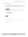
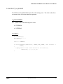
5.6.10 INT_SOURCE
The INT_SOURCE function will set the interrupt condition for a single local interrupt
request.
arg PARAMETER:
int * - Pointer to one of the following values:
•
IDLE
•
CAL_COMPLETE
•
OUTPUT_EMPTY
•
OUTPUT_LOW_QTR
•
OUTPUT_HIGH_QTR
•
OUT_BURST_READY
•
LOAD_READY
•
END_LOAD_READY
EXAMPLE:
int
int
int
FileDesc[2];
16AO12Slot = 1;
Source;
Source = OUT_BURST_READY;
if (ioctl(FileDesc[16AO12Slot], INT_SOURCE, (int) &Source) == ERROR)
{
logMsg("Interrupt Selection Failed for Slot #%d\n\n", 16AO12Slot,
0, 0, 0, 0, 0);
}
November 22, 2000
38
PMC-16AO-12 VxWorks Device Driver User’s Manual
5.6.11 ENABLE_PCI_INTERRUPTS
The ENABLE_PCI_INTERRUPTS function enables the PCI interrupts in order to have a
local interrupt request be generated.
arg PARAMETER:
Not Used.
EXAMPLE:
int
int
FileDesc[2];
16AO12Slot = 1;
if (ioctl(FileDesc[16AO12Slot], ENABLE_PCI_INTERRUPTS, 0) == ERROR)
{
logMsg("PCI Interrupt Enable Failed for Slot #%d\n\n",
16AO12Slot, 0, 0, 0, 0, 0);
}
November 22, 2000
39
PMC-16AO-12 VxWorks Device Driver User’s Manual
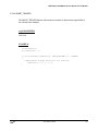
5.6.12 DISABLE_PCI_INTERRUPTS
The DISABLE_PCI_INTERRUPTS function disables the PCI interrupts.
arg PARAMETER:
Not Used.
EXAMPLE:
int
int
FileDesc[2];
16AO12Slot = 1;
if (ioctl(FileDesc[16AO12Slot], DISABLE_PCI_INTERRUPTS, 0) == ERROR)
{
logMsg("PCI Interrupts Disable Failed for Slot #%d\n\n",
16AO12Slot, 0, 0, 0, 0, 0);
}
November 22, 2000
40
PMC-16AO-12 VxWorks Device Driver User’s Manual
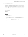
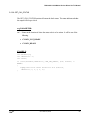
5.6.13 PROGRAM_RATE_GEN
The PROGRAM_RATE_GEN function will set the rate at which the output channels are
scanned and sampled. This function uses a user-specified divisor, iNrate. The rate
generator calculates the clock frequency as:
Frequency (Hz) = 30,000,000 / iNrate
It is advised that the iNrate value remains more than 4Bh (75 decimal).
arg PARAMETER:
int * - Pointer to the integer used in calculation.
EXAMPLE:
int FileDesc[2];
int 16AO12Slot = 1;
int iNrate;
iNrate = 0x0100;
/* Program Rate Generator. */
if (ioctl(FileDesc[16AO12Slot], PROGRAM_RATE_GEN, iNrate) == ERROR)
{
logMsg("Program Rate Generator Failed\n\n", 0, 0, 0,
0, 0, 0 );
}
November 22, 2000
41
PMC-16AO-12 VxWorks Device Driver User’s Manual
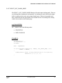
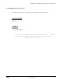
5.6.14 SELECT_ACTIVE_CHAN
The SELECT_ACTIVE_CHAN function will activate output channels. It will also set the
number of active channel in an output channel group.
arg PARAMETER:
CHAN_SELECT *
where CHAN_SELECT is defined to be
typedef struct
{
ULONG
int
ulChannels;
iNumChans;
} CHAN_SELECT;
and,
ULONG ulChannels – value to make channels active.
int iNumChans – number of channels in a channel group.
EXAMPLE:
int
FileDesc[2];
CHAN_SELECT ChannelInfo;
ULONG ulValue = 0xA08; /* Select Channels 3, 9, and 11. */
int
16AO12Slot = 1;
ChannelInfo.ulChannels = &ulValue;
ChannelInfo.iNumChans = 3;
if (ioctl(FileDesc[16AO12Slot], SELECT_ACTIVE_CHAN,
(int)&ChannelInfo) == ERROR)
{
logMsg("Active Channels Selection Failed for Slot #%d\n\n",
16AO12Slot, 0, 0, 0, 0, 0);
}
November 22, 2000
42
PMC-16AO-12 VxWorks Device Driver User’s Manual
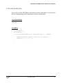
5.6.15 SET_OUT_BUFFER_SIZE
The SET_OUT_BUFFER_SIZE function will allow the user to set the analog output buffer
virtual size.
arg PARAMETER:
int * - Pointer to one of the following values:
•
OUT_BUFFER_SIZE_4
•
OUT_BUFFER_SIZE_8
•
OUT_BUFFER_SIZE_16
•
OUT_BUFFER_SIZE_32
•
OUT_BUFFER_SIZE_64
•
OUT_BUFFER_SIZE_128
•
OUT_BUFFER_SIZE_256
•
OUT_BUFFER_SIZE_512
•
OUT_BUFFER_SIZE_1024
•
OUT_BUFFER_SIZE_2048
•
OUT_BUFFER_SIZE_4096
•
OUT_BUFFER_SIZE_8192
•
OUT_BUFFER_SIZE_16384
•
OUT_BUFFER_SIZE_32768
•
OUT_BUFFER_SIZE_65536
•
OUT_BUFFER_SIZE_131072
November 22, 2000
43
PMC-16AO-12 VxWorks Device Driver User’s Manual
EXAMPLE:
int FileDesc[2];
int 16AO12Slot = 1;
int Size;
Size = OUT_BUFFER_SIZE_1024;
if (ioctl(FileDesc[16AO12Slot], SET_OUT_BUFFER_SIZE, (int) &Size) ==
ERROR)
{
logMsg("Set Output Buffer Size Failed for Slot #%d\n\n",
16AO12Slot, 0, 0, 0, 0, 0);
}
November 22, 2000
44
PMC-16AO-12 VxWorks Device Driver User’s Manual
5.6.16 GET_BUF_STATUS
The GET_BUF_STATUS function will return the status of the analog output buffer.
arg PARAMETER:
int * - Pointer to the location of where the status code is to be written. It will be one of the
following:
•
OUTPUT_EMPTY
•
OUTPUT_LOW_QTR
•
OUTPUT_HIGH_QTR
•
OUTPUT_FULL
EXAMPLE:
int FileDesc[2];
int 16AO12Slot = 1;
int Status;
if (ioctl(FileDesc[16AO12Slot], GET_BUF_STATUS, (int) &Status) ==
ERROR)
{
logMsg("Get Output Buffer Status Failed for Slot #%d\n\n",
16AO12Slot, 0, 0, 0, 0, 0);
}
November 22, 2000
45
PMC-16AO-12 VxWorks Device Driver User’s Manual
5.6.17 ENABLE_CLK
The ENABLE_CLK function will enable output clocking.
arg PARAMETER:
Not Used.
EXAMPLE:
int FileDesc[2];
int 16AO12Slot = 1;
if (ioctl(FileDesc[16AO12Slot], ENABLE_CLK, 0) == ERROR)
{
logMsg("Output Clock Enable Failed for Slot #%d\n\n",
16AO12Slot, 0, 0, 0, 0, 0);
}
November 22, 2000
46
PMC-16AO-12 VxWorks Device Driver User’s Manual
5.6.18 DISABLE_CLK
The DISABLE_CLK function will disable output clocking.
arg PARAMETER:
Not Used.
EXAMPLE:
int FileDesc[2];
int 16AO12Slot = 1;
if (ioctl(FileDesc[16AO12Slot], DISABLE_CLK, 0) == ERROR)
{
logMsg("Output Clock Disable Failed for Slot #%d\n\n",
16AO12Slot, 0, 0, 0, 0, 0);
}
November 22, 2000
47
PMC-16AO-12 VxWorks Device Driver User’s Manual
5.6.19 CLEAR_INT_REQUEST
The CLEAR_INT_REQUEST function clears the interrupt request flag after an interrupt has
occurred.
arg PARAMETER:
Not Used.
EXAMPLE:
int FileDesc[2];
int 16AO12Slot = 1;
if (ioctl(FileDesc[16AO12Slot], CLEAR_INT_REQUEST, 0) == ERROR)
{
logMsg("Clear Interrupt Request Flag Failed for Slot #%d\n\n",
16AO12Slot, 0, 0, 0, 0, 0);
}
November 22, 2000
48
PMC-16AO-12 VxWorks Device Driver User’s Manual
5.6.20 GET_CALIB_STATUS
The GET_CALIB_STATUS function will return the autocalibration status.
arg PARAMETER:
int * - Pointer to the location of where the status code is to be written. It will be one of the
following:
•
AUTOCAL_FAILED
•
AUTOCAL_PASSED
EXAMPLE:
int FileDesc[2];
int 16AO12Slot = 1;
int Status;
if (ioctl(FileDesc[16AO12Slot], GET_CALIB_STATUS, (int) &Status) ==
ERROR)
{
logMsg("Get Calibration Status Failed for Slot #%d\n\n",
16AO12Slot, 0, 0, 0, 0, 0);
}
November 22, 2000
49
PMC-16AO-12 VxWorks Device Driver User’s Manual
5.6.21 SELECT_DATA_FORMAT
The SELECT_DATA_FORMAT function will set the analog output data format to be either
offset binary or two’s compliment.
arg PARAMETER:
int * - pointer to one of the following values
•
TWOS_COMP
•
OFFSET_BINARY
EXAMPLE:
int FileDesc[2];
int 16AO12Slot = 1;
int Format;
Format = OFFSET_BINARY;
if (ioctl(FileDesc[16AO12Slot], SELECT_DATA_FORMAT, (int) &Format)
== ERROR)
{
logMsg("Select Data Format Failed for Slot #%d\n\n",
16AO12Slot, 0, 0, 0, 0, 0);
}
November 22, 2000
50
PMC-16AO-12 VxWorks Device Driver User’s Manual
5.6.22 SELECT_SAMPLING_MODE
The SELECT_SAMPLING_MODE function will set the bursting mode to either continuous or
triggered mode. With continuous mode, data is sampled continuously. With triggered burst
mode, data is sampled continuously until the buffer is empty or the end-of-frame flag is
detected.
arg PARAMETER:
int * - pointer to one of the following values
•
CONT_MODE
•
BURST_MODE
EXAMPLE:
int FileDesc[2];
int 16AO12Slot = 1;
int Mode = CONT_MODE;
if (ioctl(FileDesc[16AO12Slot], SELECT_SAMPLING_MODE, (int) &Mode)
== ERROR)
{
logMsg("Select Sampling Mode Failed for Slot #%d\n\n",
16AO12Slot, 0, 0, 0, 0, 0);
}
November 22, 2000
51
PMC-16AO-12 VxWorks Device Driver User’s Manual
5.6.23 GET_BURSTING_STATUS
The GET_BURSTING_STATUS function will return the output bursting status. The status
indicates whether there is a burst in progress. If ready, there is no bursting event.
arg PARAMETER:
int * - Pointer to the location of where the status code is to be written. It will be one of the
following:
•
BURST_NOT_READY
•
BURST_READY
EXAMPLE:
int FileDesc[2];
int 16AO12Slot = 1;
int Status;
if (ioctl(FileDesc[16AO12Slot], GET_BURSTING_STATUS, (int) &Status) ==
ERROR)
{
logMsg("Get Bursting Status Failed for Slot #%d\n\n",
16AO12Slot, 0, 0, 0, 0, 0);
}
November 22, 2000
52
PMC-16AO-12 VxWorks Device Driver User’s Manual
5.6.24 BURST_TRIGGER
The BURST_TRIGGER function will commence a transfer of data from the output buffer to
the selected active channels.
arg PARAMETER:
Not Used.
EXAMPLE:
int FileDesc[2];
int 16AO12Slot = 1;
if (ioctl(FileDesc[16AO12Slot], BUSRT_TRIGGER, 0) == ERROR)
{
logMsg("Burst Trigger Failed for Slot #%d\n\n",
16AO12Slot, 0, 0, 0, 0, 0);
}
November 22, 2000
53
PMC-16AO-12 VxWorks Device Driver User’s Manual
5.6.25 ENABLE_REMOTE_GND_SENSE
The ENABLE_REMOTE_GND_SENSE function will allow correction of a potential
difference between ground at the load and the output from the 16AO12 board. Refer to the
Systems Configuration section of the PMC-16AO-12 User’s Manual for more information
about Remote Ground Sensing.
arg PARAMETER:
Not Used.
EXAMPLE:
int FileDesc[2];
int 16AO12Slot = 1;
if (ioctl(FileDesc[16AO12Slot], ENABLE_REMOTE_GND_SENSE, 0) ==
ERROR)
{
logMsg("Enable Remote Ground Sense Failed for Slot #%d\n\n",
16AO12Slot, 0, 0, 0, 0, 0);
}
November 22, 2000
54
PMC-16AO-12 VxWorks Device Driver User’s Manual
5.6.26 DISABLE_REMOTE_GND_SENSE
The DISABLE_REMOTE_GND_SENSE function will not allow correction of a potential
difference between ground at the load and the output from the 16AO12 board. Refer to the
Systems Configuration section of the PMC-16AO-12 User’s Manual for more information
about Remote Ground Sensing.
arg PARAMETER:
Not Used.
EXAMPLE:
int FileDesc[2];
int 16AO12Slot = 1;
if (ioctl(FileDesc[16AO12Slot], DISABLE_REMOTE_GND_SENSE, 0) ==
ERROR)
{
logMsg("Disable Remote Ground Sense Failed for Slot #%d\n\n",
16AO12Slot, 0, 0, 0, 0, 0);
}
November 22, 2000
55
PMC-16AO-12 VxWorks Device Driver User’s Manual
5.6.27 SELECT_OUT_CLKING_MODE
The SELECT_ OUT_CLKING_MODE function will set the output clocking mode. There are
two clocking modes simultaneous and sequential. In simultaneous mode, data from the output
buffer is transferred to the entire active output channel group. Whereas in sequential mode,
data is transferred from the output buffer to one channel at a time in ascending order, starting
with the lowest number in the channel group.
arg PARAMETER:
int * - pointer to one of the following modes
•
SEQUENTIAL
•
SIMULTANEOUS
EXAMPLE:
int FileDesc[2];
int 16AO12Slot = 1;
int Mode;
Mode = SEQUENTIAL;
if (ioctl(FileDesc[16AO12Slot], SELECT_ OUT_CLKING_MODE, (int)
&Mode) == ERROR)
{
logMsg("Select Output Clocking Mode Failed for Slot #%d\n\n",
16AO12Slot, 0, 0, 0, 0, 0);
}
November 22, 2000
56
PMC-16AO-12 VxWorks Device Driver User’s Manual
5.6.28 SELECT_CLK_SOURCE
The SELECT_CLK_SOURCE function will set the clocking source. The clock is either from
an external source or from the internal rate generator.
arg PARAMETER:
int * - pointer to one of the following source values
•
EXTERNAL
•
INTERNAL
EXAMPLE:
int FileDesc[2];
int 16AO12Slot = 1;
int Source;
Source = INTERNAL;
if (ioctl(FileDesc[16AO12Slot], SELECT_CLK_SOURCE, (int) &Source) ==
ERROR)
{
logMsg("Select Clock Source Failed for Slot #%d\n\n",
16AO12Slot, 0, 0, 0, 0, 0);
}
November 22, 2000
57
PMC-16AO-12 VxWorks Device Driver User’s Manual
5.6.29 GET_CLK_STATUS
The GET_CLK_STATUS function will return the clock status. The status indicates whether
the output will accept a clock.
arg PARAMETER:
int * - Pointer to the location of where the status code is to be written. It will be one of the
following:
•
CLOCK_NOT_READY
•
CLOCK_READY
EXAMPLE:
int FileDesc[2];
int 16AO12Slot = 1;
int Status;
if (ioctl(FileDesc[16AO12Slot], GET_CLK_STATUS, (int) &Status) ==
ERROR)
{
logMsg("Get Clock Status Failed for Slot #%d\n\n",
16AO12Slot, 0, 0, 0, 0, 0);
}
November 22, 2000
58
PMC-16AO-12 VxWorks Device Driver User’s Manual
5.6.30 SINGLE_OUTPUT_CLK_EVT
The SINGLE_OUTPUT_CLK_EVT function will generate a single clock event.
arg PARAMETER:
Not Used.
EXAMPLE:
int FileDesc[2];
int 16AO12Slot = 1;
if (ioctl(FileDesc[16AO12Slot], SINGLE_OUTPUT_CLK_EVT, 0) == ERROR)
{
logMsg("Single Output Clock Event Failed for Slot #%d\n\n",
16AO12Slot, 0, 0, 0, 0, 0);
}
November 22, 2000
59
PMC-16AO-12 VxWorks Device Driver User’s Manual
5.6.31 SELECT_BUF_CONFIG
The SELECT_BUF_CONFIG function will set the configuration of the output buffer. The
buffer can be in a self-flushing or a circular buffer configuration. While in a circular, or closed,
configuration, data is held indefinitely. A data frame revolves through the buffer while passing
data to the active output channels. If the buffer is in the open configuration, data is passed to
the channels until the buffer is empty.
arg PARAMETER:
int * - pointer to one of the following configuration values
•
OPEN_BUF
•
CIRCULAR_BUF
EXAMPLE:
int FileDesc[2];
int 16AO12Slot = 1;
int Config;
Config = OPEN_BUF;
if (ioctl(FileDesc[16AO12Slot], SELECT_BUF_CONFIG, (int) &Config) ==
ERROR)
{
logMsg("Select Output Buffer Configuration Failed for Slot
#%d\n\n", 16AO12Slot, 0, 0, 0, 0, 0);
}
November 22, 2000
60
PMC-16AO-12 VxWorks Device Driver User’s Manual
5.6.32 LOAD_ACCESS_REQ
The LOAD_ACCESS_REQ function will request access to a circular buffer. It is necessary to
do this so that data frames can be loaded into a circular, or closed, buffer.
arg PARAMETER:
Not Used.
EXAMPLE:
int FileDesc[2];
int 16AO12Slot = 1;
if (ioctl(FileDesc[16AO12Slot], LOAD_ACCESS_REQ, 0) == ERROR)
{
logMsg("Load Access Request Failed for Slot #%d\n\n",
16AO12Slot, 0, 0, 0, 0, 0);
}
November 22, 2000
61
PMC-16AO-12 VxWorks Device Driver User’s Manual
5.6.33 GET_CIR_BUF_STATUS
The GET_CIR_BUF_STATUS function will return the circular buffer status. The status
indicates whether the circular buffer will accept new data.
arg PARAMETER:
int * - Pointer to the location of where the status code is to be written. It will be one of the
following:
•
CIR_BUF_NOT_READY
•
CIR_BUF _READY
EXAMPLE:
int FileDesc[2];
int 16AO12Slot = 1;
int Status;
if (ioctl(FileDesc[16AO12Slot], GET_CIR_BUF_STATUS, (int) &Status) ==
ERROR)
{
logMsg("Get Circular Buffer Status Failed for Slot #%d\n\n",
16AO12Slot, 0, 0, 0, 0, 0);
}
November 22, 2000
62
PMC-16AO-12 VxWorks Device Driver User’s Manual
5.6.34 CLEAR_BUFFER
The CLEAR_BUFFER function will set the output buffer to the empty state.
arg PARAMETER:
Not Used.
EXAMPLE:
int FileDesc[2];
int 16AO12Slot = 1;
if (ioctl(FileDesc[16AO12Slot], CLEAR_BUFFER, 0) == ERROR)
{
logMsg("Clear Buffer Failed for Slot #%d\n\n", 16AO12Slot, 0,
0, 0, 0, 0);
}
November 22, 2000
63