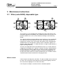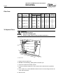
1
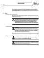
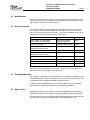
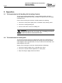
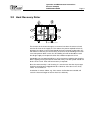
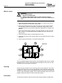
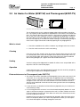
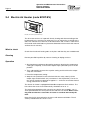
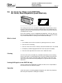
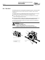
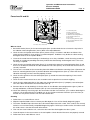
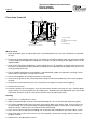
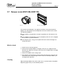
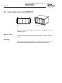
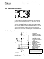
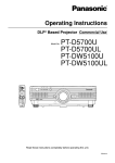
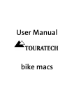
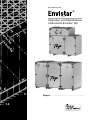
Air handling unit ® Operation and Maintenance Instructions Envistar Top Object: ......................................................... Air handling with the focus on LCC Operation and Maintenance Instructions Envistar Compact DUEC091012.03EN Contents 1 General Page 1 Unit Specification 1.1 Safety____________________________________2 1.2 Maintenance______________________________3 1.3 Service Intervals___________________________3 1.4 Spare Parts _______________________________3 Size 04 06 10 16 2 Operation 2.1 To Commission the Air Handling Unit_________4 2.2 To Commission the Cooling Unit _ ___________4 2.3 Wiring Instructions and Fuses_______________5 3 Maintenance 3.1 Filter (code ACEF), disposable type_ _________7 Supply air F5 Extract air F5 3.2 Heat Recovery Rotor_______________________9 3.3 Air Heater for Water_______________________ 11 ECET-VV ECET-TV 3.4 Electric Air Heater_________________________ 12 ECET-EV F7 F7 Cap. var. 1 2 3 3.5 Air cooler for water________________________ 13 ECET-VK ECET-DX 3.6 Fan unit__________________________________ 14 3.7 Damper (code ECET-UM, ECET-TR)_________ 17 3.8 Sound Absorber (code ECET-LD)_ __________ 18 3.9 StarCooler Cooling Unit___________________ 19 Cap. var. 1 2 3 4 Fault Tracing 4.1 Fault Tracing, Cooling Unit_________________ 22 4.2 Leakage Tracing, Cooling Unit______________ 22 Appendix, Heat Recovery Rotor Controls___________ Appendix, Controls Chapter in Envistar Catalogue__ Appendices, StarCooler Cooling Products 1 Pressure and Tightness Tests________________ 2 Safety Equipment__________________________ 3 Commissioning Report_____________________ Operation and Maintenance Instructions Envistar Compact DUEC091012.03EN Page 2 1 The continuous maintenance of this unit should be carried out by the person who has the necessary knowledge on how to perform maintenance on air handling plants. 1.1 Safety Lockable safety isolating switch A lockable safety isolating switch should be should be placed in the immediate vicinity of the unit. WARNING! The safety switch must not be used for normally starting and stopping the unit. The unit should be started and stopped from the hand-held micro terminal of the unit's control equipment. The safety switch should be locked in the 0 position while carrying out service work. Inspection doors WARNING! Before beginning work in the unit, lock the safety switch in the 0 position. Then wait at least 3 minutes before opening the inspection doors. All doors in front of moving parts should normally be locked. There are no safety guards. When access is required, unlock the doors with the key supplied with the unit. Electrical connections WARNING! The wiring of electrical connections and other electrotechnical work may only be carried out by an authorised electrician or by service personnel recommended by IV Produkt. WARNING! Rotating fan impeller. Do not energize the air handling unit until all the ducts have been connected to the unit. Operation and Maintenance Instructions Envistar Compact DUEC091012.03EN Page 3 1.2 Maintenance The continuous maintenance of this unit can either be performed by the person normally in charge of the maintenance of the building or else a contract can be signed with an authorized service company. 1.3 Service Intervals The service schedule indicates inspection and service measures for the functional sections that can be included in the air handling unit. The unit contains one or several of these functional sections. The sections included in the unit are marked on the list in the table of contents. See Page 1. Service Schedule Every 3000 h/6 mon. * Description Filter, supply air (code ACEF) Filter, extract air (code ACEF) Check pressure drop, Replace if required Page 7 Heat recovery rotor Inspection and cleaning Page 9 Air heater for water (code ECET-VV, ECET-TV) Inspection and cleaning Page 11 Electric air heater (code ECET-EV) Inspection and cleaning Page 12 Air cooler, water (code ECET-VK, ECET-DX) Inspection and cleaning Page 13 Fan unit Inspection and cleaning Page 14 Damper (code ECET-UM, ECET-TR) Inspection and cleaning Page 17 Sound absorber (code ECET-LD) Inspection and cleaning Page 18 StarCooler cooling unit Inspection and cleaning Page 19 * Every 3000nd hour of operation or 6th month depending on whichever occurs first. Service the air handling unit more often if operates in environments with high dust content in the supply and/or extract air. 1.4 Extended Warranty If the supply is covered by a 5-year guarantee, in accordance with ABM 07 with amendment ABM-V 07 or in accordance with NL 01 with amendment VU03, the IV Produkt Service and Warranty Booklet will be enclosed. In order to claim extended warranty, you must be able to present a complete documented and signed IV Produkt Service and Warranty Booklet. 1.5 Spare Parts Spare parts and accessories for this unit can be ordered from your nearest IV Produkt sales representative. Always specify the product code when ordering. You will find the codes on a separate product identification plate, affixed to each functional section. A separate spare part list is provided for the units. Page 4 Operation and Maintenance Instructions Envistar Compact DUEC091012.03EN 2 Operation 2.1 To Commission the Air Handling Unit Including Controls The Envistar Compact (code ACER) is a factory built one-piece unit that is tested and documented at the factory. It requires no special commissioning by certified persons. Prior to commissioning the contractor should attend to the following: 1. Connect the main power supply across a lockable safety isolating switch. 2. Connect the heating/cooling coil. 3. Connect all the ducts to the air handling unit. WARNING! Rotating fan impeller. Do not energize the air handling unit until all the ducts have been connected to the unit. 2.2 To Commission the Cooling Unit The Envistar Compact with rotor and StarCooler cooling unit (code ACEC) is a factory built unit tested and documented at the factory. The units that contain more refrigerant than 3 kg (StarCooler, size 16) must be commissioned by a certified refrigerant technician. Before commissioning the contractor should attend to the following. 1. Connect the power supply across a lockable main switch. 2. Connect the condensate drain pipework to a drain gulley. 3. Adjust the design supply and extract airflows. Operation and Maintenance Instructions Envistar Compact DUEC091012.03EN Page 5 2.3 Wiring Instructions and Fuses Air handling unit including controls Safety isolating switch A safety isolating switch should be installed and wired across each power supply cable. Wiring diagrams For the air handling units with controls, see the air handling unit-specific wiring diagrams supplied with the unit. Fuse protection of the unit functions The air handling functions each have a separate power supply. The following fuse protections are recommended. Cooling unit Electric air heater Size Ventilation Cap. var. 1 Cap. var. 2 Cap. var. 3 Cap. var. 1 Cap. var. 2 Cap. var. 3 04 230V+N 10AT 3×400V+N 10AT 3×400V+N 10AT – 2×400V 16A 3×400V 10A – 06 3×400V+N 10AT 3×400V+N 10AT 3×400V+N 10AT – 3×400V 10A 3×400V 16A – 10 3×400V+N 16AT 3×400V+N 10AT 3×400V+N 16AT – 3×400V 10A 3×400V 16A 3×400V 25A 16 3×400V+N 10AT 3×400V+N 16AT 3×400V+N 16AT 3×400V+N 20AT 3×400V 16A 3×400V 25A 3×400V 40A Components excl. controls The following wiring diagrams are applicable to air handling units supplied without control equipment. Fan sizes 06 and 10 Fan size 04 YELLOW/GREEN BLACK BLUE WHITE 1 WHITE 2 RED YELLOW BLUE PE L N TK/NC TK/COM PE L N POWER SUPPLY 1×230V~ 50Hz ALARM (OPENS ON AN ALARM) WHITE BROWN +10V 0-10V GND GREY PINK + – NO COM NC CONTROL 0-10V= GND Ain1 U POWER SUPPLY 1×230V~ 50Hz WHITE BROWN PINK – GREY + Rec. fuse protection Size Rec. fuse protection 10AT 06 10AT 10 10AT ALARM (CLOSES BETWEEN COM-NO ON AN ALARM) CONTROL 0-10V= Operation and Maintenance Instructions Envistar Compact DUEC091012.03EN Page 6 Fan size 16 StarCooler cooling unit (code ACEC) PE L1 L2 L3 1 POWER SUPPLY 3×400V~ 50Hz See Table: Fuse protection for separate power supply below 3 5 N PINK – GREY + GND Ain1 U PE ALARM (CLOSES BETWEEN COM-NO ON AN ALARM) WHITE BROWN NO COM NC START/STOP (230 V) 102 103 CONTROL 0-10V= ALARM (CLOSES ON AN ALARM) 208 209 Capacity variant / rec. fuse protection Rec. fuse protection 10AT Heat recovery rotor L POWER SUPPLY 1×230V~ 50Hz N PE 33 34 WHITE BROWN 37 41 43 – CONTROL 0-10V= 1 2 3 04 3×400V+N 10AT 3×400V+N 10AT – 06 3×400V+N 10AT 3×400V+N 10AT – 10 3×400V+N 10AT 3×400V+N 16AT – 16 3×400V+N 16AT 3×400V+N 16AT 3×400V+N 20AT Electric air heater (code ECET-EV) COOLING RECOVERY (CLOSED CONTACT SWITCHES IN FULL SPEED) 36 42 + Size GREEN YELLOW See Table: Fuse protection for separate power supply below L1 L1 L2 L2 L3 PE ALARM (CLOSES ON AN ALARM) L OPERATION 230 V~ N PE Rec. fuse protection 10AT Y + G0 – 1 NC 2 3 NO 4 CONTROL 0-10 V= ALARM (CLOSES BETWEEN 3-4 ON AN ALARM Capacity variant / rec. fuse protection Size 1 2 3 04 2×400V 16A 3×400V 10A – 06 3×400V 10A 3×400V 16A – 10 3×400V 10A 3×400V 16A 3×400V 25A 16 3×400V 16A 3×400V 25A 3×400V 40A Operation and Maintenance Instructions Envistar Compact DUEC091012.03EN Page 7 3 Maintenance Instructions 3.1 Filter (code ACEF), disposable type Filter Filter The air filters in an air handling plant should prevent dust and particles from being discharged into the building. They should also protect the sensitive components inside the unit, such as coils and heat exchangers, from becoming fouled. The collecting efficiency between different types of filter may vary considerably. The capacity to accumulate particles also varies substantially. Therefore it is important to use filters of the same quality and capacity when changing filters. Standard filter class designations specify a filter's collection capacity. G4 denotes a basic filter and F5 – F7 denote fine filters; a higher number denotes a higher collecting efficiency. The filters are disposable and are intended for one time use. As filters become clogged the air handling unit's capacity is reduced. The filters should therefore be exchanged if the pressure drop across the filter exceeds a predetermined final pressure drop. It is important to stop the unit prior to changing filters so that dust will not be shaken free and be sucked into the unit. The filter sections should therefore also be cleaned when changing the filters. What to check Check the pressure drop across the filters. The pressure drop can be measured by means of a manometer connected to the measurement tappings. Connect the measurement tappings on each side of the filters. If the final pressure drop is reached, the filters should be replaced. Operation and Maintenance Instructions Envistar Compact DUEC091012.03EN Page 8 Filter Data Dimension (mm) Size Type of filter Qty. of filters 04 Bag filter F5-F7 1 650×287 320 F5 F7 1.7 2.2 120 160 06 Bag filter F5-F7 1 790×287 370 F5 F7 2.5 3.1 140 175 10 Bag filter F5-F7 1 892×409 370 F5 F7 4.0 4.9 150 185 16 Bag filter F5-F7 2 592×592 370 F5 F7 2 × 3.3 2 × 4.6 130 170 Frame Length Filter class Surface, Rec. final prestotal (m²) sure drop (Pa) To Replace Filters WARNING! Before beginning work: 1. Stop the air handling unit. 2. Turn the safety switch to the 0 position and lock it. To replace filters 1. Release the eccentric rails. 2. Withdraw the old filter(s), pulling it/them towards you. 3. Clean the interior of the filter section. 4. Fit the new filter(s) and push in the eccentric rails and close the inspection door. 5. If the section has a mounted filter monitor: fasten the measuring elements on each side of the filter. 6. Start the unit. Operation and Maintenance Instructions Envistar Compact DUEC091012.03EN Page 9 3.2 Heat Recovery Rotor Heat recovery rotor The function of the heat exchanger is to recover heat from the extract air and transfer this heat to the supply air. This reduces the power required to heat air; therefore less power is consumed. Should the heat exchanger malfunction, this will reduce its efficiency on heat recovery and cause the air handling unit to consume more power. What’s more, the air handling unit will not be able to reach the design supply air temperature when the outdoor temperature is low. A probable cause of reduced efficiency on heat recovery could be that the drive belt is slipping causing the rotor to rotate too slowly. The rotor speed should not be less than 8 r/min. when full heat recovery is required. Since the rotor normally is self cleaning, it is not common that the air passages inside the rotor become clogged with dust. However, if the dust is of a sticky nature, this could occur. A reduction in extract airflow, e.g. if the extract air filter becomes fouled, will cause the heat exchanger to recover heat less efficiently. Operation and Maintenance Instructions Envistar Compact DUEC091012.03EN Page 10 What to check WARNING! Before beginning work: 1. Stop the air handling unit. 2. Turn the safety switch to the 0 position and lock it. Avoid touching the inlet and the outlet surfaces of the rotor with hands or tools. 1. Check that the rotor rotates easily. If it is sluggish, it may be necessary to adjust the position of the bristled sealing strip. 2. Check that the bristled sealing strip of the rotor is in close contact against the side plates, and that it is not worn. The bristled sealing strip is a consumption part that may need to be adjusted or replaced if it no longer seals properly. 3. Check that the drive belt is properly stretched and does not slip. If the belt slips, shorten it. The speed of the rotor should be at least 8 r/min for max. heat recovery. 4. Check that the drive belt is not damaged and is clean. 5. Check that the inlets of the rotor passages are not coated with dust or other impurities. 6. Check the pressure balance, see the illustration below. ECET-TR P4 P3 P1 P2 Check the pressure balance To ensure proper purging sector function, sub-atmospheric pressure P3 should be greater than P2. If not, use the ECET-TR trim damper on the extract air side to throttle to the correct pressure balance. Cleaning Remove dust by carefully vacuum cleaning or by using a soft brush. If the rotor is laden with greasy dust, it can be sprayed with water mixed with dishwashing detergent (of a type that will not corrode aluminium). Low-pressure compressed air (max. 6 bar atmospheric gauge) can be used for blowing surfaces dry. Do not hold the nozzle closer than 5–10 mm to the rotor surface. Lubrication The bearings and drive motor are permanently oiled and require no lubrication. Operation and Maintenance Instructions Envistar Compact DUEC091012.03EN Page 11 3.3 Air Heater for Water (ECET-VV) and Thermoguard (ECET-TV) Air heater, water (code ECET-VV) and Air heater, water, Thermoguard (code ECET-TV) The air heater consists of a number of copper tubes with pressed-on aluminium fins. The capacity of the coil becomes impaired if the coil surfaces are coated with dust. This not only decreases heat transfer; it also increases the pressure drop on the air side. Even if the ventilation system is equipped with good filters, with time, dust will collect on the front edge of the fins of the coils (the inlet side). To utilize the coil's full capacity, it must be well vented. Venting is carried out by opening air relief screws in pipe connections and/or by opening the air purging device. What to check 1. Check the condition of the coil fins to detect any damage to the face surface. 2. Check to make sure that the coil is not leaking. Cleaning If the fins on the coils are dirty: clean by vacuum cleaning them from the inlet side. Or, carefully blow them clean with compressed air from the outlet side. If the surfaces are heavily laden with impurities, spray them with warm water mixed with dishwashing detergent (of a type that will not corrode aluminium). Venting Vent the heating coil and pipework if needed. Air relief screws are provided at the top of the coil or the connection pipes. Operation Check that hot water is circulating properly through the coil. Do this by temporary increasing the temperature setting (the set point). Extra maintenance for Thermoguard (code ECET-TV) 1. The safety valve action should be checked regularly (at least once per year). If the valve leaks, this is normally due to dirt from the pipework that has collected on contact surfaces inside the valve. Normally just carefully turning the valve knob is enough to "flush" the valve seat clean from dirt. If the valve continues to leak, it will have to be replaced. A new valve of the same type and same size of opening must be used. 2. If shut-off valves are fitted to the inlet and return pipework, they must not be closed if freezing is likely. 3. If a Thermoguard-coil has frozen, it must be thawed completely before it is used again. If the heat exchanger is upstream of the coil, it is often sufficient to run the heat exchanger to thaw the coil. If this does not work, some external heat source must be used to thaw the coil. Important! To ensure correct Thermoguard coil operation, allow the entire coil to thaw out completely before you make it fully operational. When you start up the unit, check that liquid is circulating through the entire coil. Page 12 Operation and Maintenance Instructions Envistar Compact DUEC091012.03EN 3.4 Electric Air Heater (code ECET-EV) Electric air heater (code ECET-EV) The air heater consists of "exposed" electric heating rods. Severe fouling of the heating rods may cause them to overheat. This can shorten the useful life of the rods. This will also cause them to smell of burnt dust and, at worst, make them a fire hazard. Overheated rods may become deformed or loosen from their mounts and heat the air unevenly. What to check Check that the electric heating rods are in place and that they are not deformed. Cleaning Remove possible impurities by vacuum cleaning or wiping surfaces. Operation 1. Simulate decreased power demand by temporary lowering the temperature setting (the set point), so that all the output steps (contactors) are in the off position. 2. Then substantially increase the set point setting and check that the output steps are switched in. 3. Reset the temperature setting. 4. Stop the unit (Caution! Do not switch off with the safety switch). All the output steps should switch out (=contactors in the off position). The fans in the unit will continue to operate for approx. 2 – 5 minutes to cool the thermal energy stored in the air heater. The electric air heater is equipped with double temperature limit switches. The limit switch that resets itself automatically should be set to 70 °C. The overheating protection with manual reset switches out at approx. 120 °C and is positioned on the cover panel on the side of the air heater. Before resetting, find out what has caused the air heater to overheat and remedy the fault. Note that the risk for overheating increases with decreased airflow. The air velocity should not be less than 1.5 m/s. Operation and Maintenance Instructions Envistar Compact DUEC091012.03EN Page 13 3.5 Air Cooler for Water (code ECET-VK), Air Cooler, Direct Expansion (code ECET-DX) Air cooler for water (code: ECET-VK) and Air cooler, direct expansion (code: ECET-DX) The cooling coil consists of a number of copper pipes with pressed-on aluminium fins. If the coil surfaces become coated with dust, this will decrease the capacity of the coil. This will also decrease heat transfer and increase the pressure drop on the air side. Even if the ventilation system is equipped with good filters, with time, dust collects on the front edge of the fins of the coils (the inlet side). A condensate drip tray is fitted underneath the cooling coil for condensate drainage. What to check Check: 1. The condition of the coil fins to detect any damage to the face surface 2. That the coil is not leaking 3. That the surface of the coil is uniformly cool (while chilled water is circulated) 4. The drip tray and drainage pipework with water trap (clean if needed) 5. That the water trap without non-return valve is filled with water. Cleaning If the fins of the coils are fouled, they should be cleaned by vacuum cleaning from the inlet side. Or, carefully blow them clean with compressed air from the outlet side. If the surfaces are heavily laden with impurities, spray them with warm water mixed with dishwashing detergent of a type that will not corrode aluminium. Venting (N.B! Applies to the ECET-VK only) Vent the cooling coil and pipework if needed. Air relief screws are provided at the top of the coil or on the branch pipes. Operation Check that water is circulating properly through the coil. Do this by temporary decreasing the temperature setting (the set point). Operation and Maintenance Instructions Envistar Compact DUEC091012.03EN Page 14 3.6 Fan Unit The function of the fans is to transport air through the system, i.e. the fan should overcome the flow resistance which is present in air devices, ducts and unit components. The speeds of the fans are adjusted to generate correct airflow. If the fans generate a lower flow, this impairs the function of the ventilation system. If the supply airflow is too low, this will cause an imbalance in the system, which can lead to poor room climate. If the extract airflow is too low, the ventilating capacity will be too poor. Such an imbalance may cause damp air to penetrate the building structure. One reason why fans generate too low an airflow can be that the impeller blades are coated with dust. WARNING! Before beginning work: 1. Stop the air handling unit. 2. Turn the safety switch to the 0 position and lock it. 3. Wait three minutes before you open the fan section door. 2 2 1 1 3 Fan unit, sizes 04 and 06 1. EC motor with controller 2. Fan impeller 3. Anti-vibration mountings Fan unit, sizes 10 and 16 3 Operation and Maintenance Instructions Envistar Compact DUEC091012.03EN Fans sizes 04 and 06 7 9 5 4 Page 15 3 2 1 6 8 2 1. Connection plate 2. Bolts (suspension) 3. Anti-vibration mounting 4. Vibration attenuating bracket 5. Fan impeller with motor 6. Inlet cone 7. Fan mounting bracket, upper 8. Fan mounting bracket, lower 9. Terminal box Fan unit, sizes 04 and 06 What to check 1. Back off the bolts (item 2) in the connection plate (item 1) and unhook the fan unit from the key holes in the vibration attenuating brackets (item 4) both at the top and bottom. 2. Check that the fan impeller with motor (item 5) rotates easily, is in balance and does not vibrate. Also check that the impeller is clean and has no particle deposits. Unbalance may be due to a dust coating damaged surfaces on the impeller blades. 3. Listen to the sound from the bearings. If the bearings are as they should be, a weak humming sound can be heard. A scraping or pounding sound may indicate that the bearings are damaged. If this is the case, servicing is required. 4. Check that the fan impeller with motor (item 5) is secured to the upper fan mounting bracket (item 7) and that it has not become shifted to the side towards the inlet cone (item 6). Also check that the inlet cone is securely mounted. 5. The fan unit is mounted on the connection plate with rubber anti-vibration mountings (item 3) between the lower fan mounting bracket (item 8) and the vibration attenuating brackets (item 4). Check that the antivibration mountings are intact and are properly secured. 6. Check that the gasket on the connection plate (item 1) around the connection opening is intact and is properly secured. 7. Check that the measurement hoses are secured to each respective measurement tapping. 8. Check that the edge protection on the upper fan mounting bracket (item 7) is properly secured and protects the cables connected in the terminal box (item 9). 9. Remount the fan unit by hooking it in the key holes in the vibration attenuating brackets (pos 4), both at the top and bottom, and fasten the bolts (item 2) in the connection plate (item 1). 10. Check the airflow by measuring Δp in the connections for flow measurement. Δp is used for obtaining the airflow in a chart affixed to the air handling unit. on the U-tube manometer. Plot from Δp in the chart (affixed on the unit) for the relevant unit size and read the flow. Cleaning 1. Follow items 1-8 under What to check. 2. Wipe the impeller blades clean to remove possible deposits. Use an Eco-friendly degreasing agent. 3. The motor should be kept clean from dust, dirt and oil. Wipe clean with a cloth. If the surfaces are severely fouled, use an environmentally compatible degreasing agent. If thick layers of dirt restrict air intake to cool the stator, there is risk that the motor will overheat. 4. Then vacuum clean inside the unit, so that the dust won't be discharged to the duct system. 5. Clean other parts in the same manner as the fan impellers. Check that the inlet cones are properly secured. 6. Follow items 9-10 under What to check. Operation and Maintenance Instructions Envistar Compact DUEC091012.03EN Page 16 Fans, sizes 10 and 16 5 4 1 3 2 1. Fan unit bolts 2. Pins 3. Anti-vibration mountings 4. Motor 5. Fan impeller Fan unit, sizes 10 and 16 What to check 1. Back off the bolts (item 1) and the pins (item 2) and withdraw the fan units (fan and motor are mounted on rails). 2. Check that the fan impellers rotate easily, are in balance and do not vibrate. Also check that the impeller is clean without particle deposits. Unbalance may be due to a dust coating or damaged surfaces on the impeller blades. 3. Listen to the sound from the bearings. If the bearings are as they should be, a weak humming sound can be heard. A scraping or pounding sound may indicate that the bearings are damaged. If this is the case, servicing wil be necessary. 4. The fan impeller and motor are mounted on a stand fitted with rubber anti-vibration mountings. check that the latter are properly secured and are intact. 5. Check mounting bolts and suspension devices and stand. 6. Check that the gasket on the connection plate around the connection opening is intact and is properly secured. 7. Check that the measurement hoses are secured to each respective measurement tapping. 8. Remount the fan units. 9. Check the airflows by measuring the Δp in the connections for flow measurement. Δp is used for obtaining the airflow in a chart affixed to the air handling units. Read the pressure differential Δp on the U-tube manometer. Plot from Δp in the chart for the relevant unit size and read the flow. Cleaning 1. Follow items 1-7 under What to check. 2. Wipe the impeller blades clean to remove possible deposits. Use an Eco-friendly degreasing agent. 3. The motor should be kept clean from dust, dirt and oil. Wipe clean with a cloth. If the surfaces are severely fouled, use an environmentally compatible degreasing agent. If thick layers of dirt restrict air intake to cool the stator, there is risk that the motor will overheat. 4. Then vacuum clean inside the air handling unit so that dust will not be blown out into the duct system. 5. Clean other parts in the same manner as the fan impellers. Check that casings and inlet cones are properly secured. 6. Follow items 8-9 under What to check. Operation and Maintenance Instructions Envistar Compact DUEC091012.03EN Page 17 3.7 Damper (code ECET-UM, ECET-TR) Size 04 Sizes 06, 10 and 16 The function of the dampers is to regulate the airflow. If they do not operate properly, this will disturb ø315the overall operation of the unit and will cause serious consequential problems. �If the outdoor air damper does not open completely, this will reduce the airflow. 210 �If the outdoor air damper does not shut completely when the unit is stopped, the air heater may freeze and burst. �If the damper leaks, energy consumption will increase due to leakage caused by thermal lift. What to check 1. Check how the actuator operates. 2. Check that the damper blades seal tightly when they are supposed to be closed. If not, adjust the actuator so that they will seal tightly (does not apply to trim dampers). 3. Check the condition of the sealing strips. 4. If the damper will not operate, check to make sure that some screw has not inadvertently been fitted through the drive mechanism/damper blades, preventing damper operation. Cleaning Wipe the damper blades clean with a cloth. Use an environmentally compatible degreasing agent if they are considerably fouled. Operation and Maintenance Instructions Envistar Compact DUEC091012.03EN Page 18 3.8 Sound Absorber (code ETET-LD) Size 04 Sizes 06, 10 and 16 The function of the sound absorber is to reduce the sound power level in the ventilation system. What to check Check that the baffle elements have flawless and clean surfaces. Adjust as required. Cleaning Vacuum clean and/or wipe all surfaces with a damp cloth. If the surfaces are substantially fouled, rotating nylon brushes can be used for cleaning. Operation and Maintenance Instructions Envistar Compact DUEC091012.03EN Page 19 3.9 StarCooler Cooling Unit StarCooler All cooling and heat pump units operate according to the same principal. The unit moves the heat contained in media such as air, water, gas etc. from one place where the heat is not desirable or needed, to a place where it is possible to make use of the heat, or get rid of it. Your unit is designed and installed to meet specific demands. Special components have been selected and combined, in order for these demands to be met with optimal safety and at the lowest total cost. The unit has been designed in accordance with certain basic prerequisites, which must exist for it to function. These prerequisites cannot be changed without checking that the unit can handle this change. How the cooling circuit operates 13 1 Compressor 2 Condenser 3 High pressure switch 3 4 Measurement tappings, high pressure 5 Drying filter 6 Sight glass (size 16) 7 Thermostatic expansion valve 8 Mixing valve 9 Capacity regulator 10 Evaporator 2 1 9 4 12 5 6 11 7 11 Measurement tappings, low pressure 12 Low pressure switch 13 Exhaust air fan 14 Supply air fan 8 10 R134a refrigerant charge (kg) 14 Cooling circuit ACEC 04 ACEC 06 ACEC 10 ACEC 16 1.5 2.5 3.0 6.0 The refrigerant in the cooling circuit absorbs heat in the cooled object via the evaporator. The refrigerant evaporates, its pressure decreases transforming it from liquid to gas. Operation and Maintenance Instructions Envistar Compact DUEC091012.03EN Page 20 The cold suction gas which now has absorbed heat out of the cooled space/medium, is sucked back to the compressor, where it is compressed and heated. In all total hermetic compressors, the suction gas is also used to cool the compressor's electric motor. The refrigerant now contains both the heat from the cooled item, the motor heat of the compressor and compression heat. The refrigerant is pressed as hot gas from the compressor to the condenser, where emits heat. As it cools, the refrigerant condenses from gas to liquid. This is repeated, in a totally closed system, until the temperature in the cooled/heated medium is down/ up to the temperature that has been preset. Operation - Control Interlocking The cooling unit is interlocked across the supply air and extract air fans. If any of the fans stops, the cooling unit will also stop. Operation COOLING operation The cooling compressor starts when the potential-free contact from the controller closes. Interlocking The compressor is interlocked with the ventilation unit. When the ventilation unit stops, the potential-free contact for cooling operation opens and the compressor stops. Compressor Protection The motor protection trips, the compressor stops, the group alarm contact closes, and an alarm is transmitted to the controller in the event of an over-current or safety circuit alarm. In the event of an alarm, remedy the fault and reset the motor protection. N.B! Each high pressure switch has a manual reset button. The safety circuit alarm trips in the event of two different kinds of faults. • High pressure in the system, HP • Low pressure in the system, LP If the safety circuit alarm trips repeatedly, contact an authorised refrigeration service firm. Electrical Connections Junction box contains the following: • Protective motor switch • Contactor • Starting equipment The junction box is mounted in the cooling unit and has been internally fully wired and tested at the factory. For a Wiring Diagram see Section 2 Operation, wiring instructions and the fuse protections. Operation and Maintenance Instructions Envistar Compact DUEC091012.03EN Page 21 Summary of certain rules in the Swedish Proclamation Regulating the Use of Refrigerants One-piece units containing volumes of refrigerant less than 3 kg The maintenance and care of these units should take place showing sound judgement under certain responsibility. This implies that no new refrigerant may e.g. be charged before any leakage in the unit has been sealed. Moreover, refrigerant emptied from the unit must always be taken care of and either it has to be reused or sent for destruction. Regarding service and maintenance, no proof of authorisation by authorities is required for the person servicing the unit. Though the unit must be serviced with general sound judgement. If servicing requires some form of modification of the refrigeration circuit, this must only be carried out by a person with certified skills. No report need be filed with the authorities in conjunction with servicing these units. In project planning calculations, one-piece units that have a refrigerant volume of no more than 3 kg shall be considered not to contain any refrigerant at all. This means that, according to the above, anyone can add any number of onepiece units to the ventilation system without having to calculate on increased refrigerant volume. One-piece units containing volumes of refrigerant more than 3 kg Over and above what has been stated above, the relevant cooling unit and components of these ventilation systems should be inspected at least once every 12 months. A journal should be kept. Permission/authority is required for carrying out this work. A report of the inspections carried out must be submitted to the Environmental and Public Health Protection Authority in the relevant local authority. The owner of the ventilation system is responsible for seeing to it that above provisions are carried out. Maintenance Instructions and Procedures General This section of the instruction is general. It is intended to enable simple periodic inspection of the unit and show, in the event of a breakdown, what simple checks can be made before calling for skilled service help. The accompanying wiring diagrams and special instructions for the components included in the system will provide the necessary information for more complicated modifications in the system. Periodic inspection 1. Appoint one or a few persons skilled in this field to assume responsibility for continuous inspection of the cooling system. Make sure that these persons are familiar with how the system operates and where the components of the system are located. 2. The cooling system is designed to operate automatically. Make sure that the settings are not altered by anyone who lacks sufficient knowledge of how the system operates. 3. Make sure that the machine room or some other location where system components are installed is kept clean. 4. Check that liquid can flow freely in the drainage pipework. 5. If you are unsure of anything in or near your cooling system? Get in touch with your supplier! It may often be better and less inexpensive to call too often than too seldom. Page 22 Operation and Maintenance Instructions Envistar Compact DUEC091012.03EN 4 Fault Tracing 4.1 Fault Tracing Schedule for the Cooling Unit Symptom Possible Cause Too high temperature in coo- The power supply is isolated. led object/medium Remedial Measure Check the control/safety switch and fuses. No flow or bad flow across evaporator Check that nothing stops the flow. The thermostat/control equipment is set wrong/faulty. Adjust the setting or replace the equipment. The capacity controller is set for excessively high opening pressure. Turn the opening screw anti-clockwise 1/6 of a turn at a time, read the temperature change after 5 minutes, etc. The compressor is not operating. See "Compressor" Compressor is not operating The power supply is isolated. Check the control/safety switch and fuses. The compressor safety circuit has opened. Malfunctioning compressor. The compressor is switched Insufficient refrigerant. out by the low pressure switch No flow or bad flow across evaporator Check and reset, if needed. Expansion valve is defective. Faulty low pressure switch. The compressor is switched No flow or bad flow across the con out by the high pressure denser. switch Faulty high pressure switch. Severe icing on the evapora- Expansion valve is incorrectly set/ tor defective. Insufficient refrigerant. Determine the fault. Replace compressor. The system has a leak. Seal the leak and charge more refrigerant. Check the flow. Check, replace. Check, replace. Check the flow across the condenser. Check, replace. Check, replace. Check the sight glass. The system has a leak. Seal the leak and charge more refrigerant. 4.2 Leakage Tracing in the Cooling Unit A leak can arise in the refrigeration system. This can be readily seen mainly by impaired cooling performance or, if the leakage is instantaneous, that the system will not operate at all. An accumulation of oil on pipes, insulation, etc. may indicate refrigerant leakage. IF YOU SUSPECT THAT REFRIGERANT IS LEAKING FROM THE SYSTEM AND YOU NOTICE THAT THE COOLING UNIT IS PERFORMING POORLY – CALL FOR AUTHORIZED SERVICE ASSISTANCE. Keep in mind that the refrigerant must not be released in the atmosphere and that escaping refrigerant can cause burns if it comes in contact with skin. Always wear personal safety equipment whenever you work with refrigerant circuits. ONLY ACCREDITED INSPECTORATES – COMPANIES WITH REQUIRED AUTHORIZATION SHALL BE ALLOWED TO WORK WITH OR MODIFY THE REFRIGERANT SYSTEM. IV Produkt AB, P.O. 3103, SE-350 43 Växjö, SWEDEN Phone: +46 470 75 88 00 • Fax: +46 470 75 88 76 [email protected] • www.ivprodukt.se DUET091012.03EN Air handling with the focus on LCC