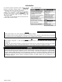
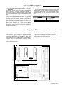
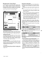
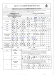
1
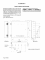
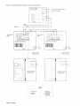
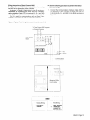
Introduction
This manual provides information about the MicroTech”
MicroTech Absorption Gateway (MAG). It describes the
components, field wiring, and service procedures.
The MAG is an interface between the absorption
chiller(s) and a MicroTech or Open ProtocolTM building
automation system (BAS). The MAG allows the BAS to read
data from the absorption chiller, but does not allow the
control of the chiller.
See Table 1 for the items that can be read from the absorption chiller through the MAG.
Table 1. Read-Only Data
Electric shock hazard. Can cause personal injury or equipment damage.
This equipment must be properly grounded. Connections and service to the MicroTech control panel must be performed
only by personnel that are knowledgeable in the operation of the equipment being controlled.
Static sensitive components. A static discharge while handling electronic circuit boards can cause damage to the
components.
Discharge any static electrical charge by touching the bare metal inside the control panel before performing any service
work. Never unplug any cables, circuit board terminal blocks, or power plugs while power is applied to the panel.
This equipment generates, uses and can radiate radio frequency energy and, if not installed and used in accordance with
this instruction manual, may cause interference to radio communications. It has been tested and found to comply with the
limits for a Class A digital device, pursuant to part 15 of the FCC rules. These limits are designed to provide reasonable
protection against harmful interference when the equipment is operated in a commercial environment. Operation of this
equipment in a residential area is likely to cause harmful interference in which case the users will be required to correct the
interference at their own expense. McQuay International disclaims any liability resulting from any interference or for
the correction thereof.
Page 4 / IM 620
General Description
The MicroTech” Absorption Gateway (MAG) is a microprocessor-based controller used as a read-only interface between a MicroTech absorption chiller and a MicroTech or
Open Protocol partner’s building automation system (BAS).
No control of the absorption chiller is performed through the
MAG.
A MAG is needed for each absorption chiller in a network. If there is only one absorption chiller, a single MAG
can connect to the Open Protocol partner’s integrator, or
stand alone as its own network. This type of configuration is
called the Direct Connect MAG. If there are two or more
absorption chillers, a level-l controller such as a Network
Master Panel (MicroTech) or an Open Protocol Master
Panel (Open Protocol) is needed to read and store information from the chillers. This type of configuration is called the
Network Connect MAG.
The base panel is equipped with eight AC power rated
relays plus the necessary hardware to support the addition
of accessories listed in Table 2. For more information on the
MAG accessories, see the “Accessories” section in this
manual.
Table 2. MAG Accessories
Analog Output Expansion Module
(AOX-4)
Solid-State Relay Kit (SSR)
Adds analog outputs
Adds digital outputs
Component Data
Figure 1 shows the control panel layout for the MAG. The
main components of the controller are the Microprocessor
Control Board (MCB), the Output Board (OB) and the Input
Conditioning Module (ICM) Terminal Board. All of these
major components are mounted inside a standard NEMA 1
enclosure. They are interconnected by ribbon cables,
shielded multi-conductor cables, or discrete wiring. Power
for the system is provided by transformers T1 and T2.
Following are descriptions of these MicroTech components and their input and output devices.
Figure 1. MAG Panel Layout
IPI!
0
I- ICM Terminal Board
Snap Track
0
0
IM 620 / Page 5
Microprocessor Control Board
The Microprocessor Control Board (MCB) is shown in Figure 2. It contains a microprocessor that is preprogrammed
with the software required to monitor the data from the
absorption chiller(s) and other equipment that is connected
to the MAG such as sensors or actuators. The various MCB
connections and components are described below.
Figure 2. Microprocessor Control Board (MCB)
I I
II
Microprocessor Status LEDs
The green, red, and amber LEDs on the MCB provide information about the operating status of the microprocessor.
The amber LED also indicates the existence of alarm
conditions.
Following IS the normal start-up sequence that the three
status LEDs should follow when power is applied to the
MCB:
The red (“Reset”) LED turns on and remains on for
approximately 5 seconds. During this period the MCB
performs a self-test.
The red LED turns off and the green (“Running”) LED
turns on. This indicates that the microprocessor has
passed the self-test and is functioning properly.
The amber (“Active”) LED remains on for 1 second and
off for 1 second when communications exists between
the MAG and the absorption chiller. If the LED is on for
YIO of a second and off for 710 of a second, this indicates that communications between the MAG
and the absorption chiller does not exist.
r
L Microprocessor status LED’s
POWER FUSES
[BUSSMAN GDC-TZA,
b
I
i
E
g
::
2
z
If the above sequence does not occur after power is
applied to the controller, there is a problem with the MCB or
its power supply. For more information, refer to the “Test
Procedures” section of this manual, which is under “Service
Information.”
Tables 3 and 4 summarize the green, red, and amber
status LED indications.
Table 3. Green and Red Status LED Indication
n
Digital Outputs Connection
After processing all input conditions and network data, the
MCB sends the appropriate output signals to output devices
through the Digital Outputs port via a plug-in ribbon cable.
Aux/Out Terminal Strip
The Aux/Out terminal strip provides 5 Vdc and 13 Vdc to
the MAG field wiring terminal strip. The 5 Vdc is used to
power auxiliary equipment. The 13 Vdc can be used to
power an Analog Output Expansion Module (see the
“Accessories” section of this manual for more information
on the Analog Output Expansion Module).
Power In Connector
The MCB receives 18 Vac, center-tapped power from
transformer T2 through the Power In connector. This power
drives all logic and communications circuitry, and the
Aux/Out terminal strip. Refer to the panel’s wiring diagram
or Figure 15 for more information.
Power Fuses
Two identical 2-amp fuses are located to the right of the
Power In terminal strip. These fuses are in the MCB power
supply circuit.
Page 6 / IM 620
* For longer tharl 5 seconds.
Table 4. Amber Status LED Indication
the MAG and the absorption chiller
Hex Switches
The MCB includes two hex (hexadecimal) switches that are
used to set the MAG controller’s network address.
The HI and LO hex switches are shown in Figure 3. A
“hex switch setting” is defined as the HI switch digit followed
by the LO switch digit. For example, a hex switch setting of
2F would have the HI switch set to “2” and the LO switch
set to “F.” Refer to “Addressing the Controllers” in the
“Network Commissioning” section of this manual for more
information
Note: You can change the setting of a hex switch with a
slotted-blade screwdriver that has a Y32-inch tip. If a hex
switch setting is changed, power to the MCB must be cycled in order to enter the new setting into memory. This can
be done by turning the panel’s power switch off and then
back on.
Figure 3. Hex Switches
HI (left)
hex switch
LO (right) hex switch
Port B: Port B is for network communications between
the MAG and the absorption chiller, or the MAG and the
level-l MicroTech controller using the RS-485 interface
standard. A twisted, shielded pair cable should be connected to port B via terminals B+, B-, and GND on terminal
block T11 . The communications rate is 9600 baud. For
more information, see “Network Communications” in the
“Field Wiring” section of this manual.
Output Board
* Hex switch setting 01 shown
Expansion Bus Connection
The Expansion Bus connector sends output signals to the
Analog Output Expansion Module (see the “Accessories”
section) via a ribbon cable. The output signals are used by
the Analog Output Expansion Module to drive various control devices.
Communication Ports
The MCB has two communication ports: port A and port B.
Each port has six terminals and is set up for both the RS232C and RS-485 data transmission interface standards.
The male and female connectors for these ports are
manufactured by AMP. Therefore, they are referred to as
“AMP plugs” or “AMP connectors” throughout this manual.
Socketed fuses located next to the ports protect the communications drivers from voltage in excess of +12 V. Following are brief descriptions of each port’s function.
Port A: Port A is for communications with an absorption
chiller unit controller, another manufacturer’s BAS interface
device, or an IBM compatible PC using the RS-232C interface standard. When port A is used for communications
with the absorption chiller unit controller, the communications rate is 4800 baud with an interface standard of RS485. When port A connects to the BAS interface device or a
PC, the communications rate is 9600 baud. The PC can be
directly connected, over a limited distance, with a twisted,
shielded pair cable. For more information, see “PC Connection” in the “Field Wiring” section of this manual.
The Output Board (OB) accepts up to 24 digital outputs
from the MCB. Each output has fused sockets and can be
used to drive an AC or DC load by selecting a particular
relay output module. Screw terminals allow for field wiring
connections to the output device. Each output has an onboard LED that illuminates when an output socket that
contains a relay is activated by the MCB. Following are the
Output Board’s power ratings.
l
l
120V - 50/60 Hz
250V - 50160 Hz
Input Conditioning Module
Terminal Board
The Input Conditioning Module (ICM) Terminal is provided
for possible future applications. The ICM Terminal Board
has three edge card connectors, field wiring terminals for
analog and digital inputs, field wiring terminals for 5 Vdc
and 24 Vac, field wiring terminals for communication ports,
and ribbon cable connections to the MCB.
Power
Above each edge card connector are field wiring terminals
for 5 Vdc (regulated) and 24 Vac (ground referenced).
These terminals can be used to power peripheral devices. It
is also used to power the LEDs in the Output Board.
Communications
Also located on the ICM Terminal Board are communications field wiring terminals. Terminals B+, B-, and GND
connect to either a level-l controller’s communications field
wiring terminals or to the absorption chiller. Terminals A+,
A-, and GND connect to the BAS integrator, the absorption
chiller, or a PC. Both sets of terminals have an AMP connector that attach to the MCB port A and port B.
Software ID
MicroTech software is factory installed and tested in each
panel prior to shipment. The software is identified by a
program code (also referred to as the “Ident”). The program
code is encoded in the controller’s memory and is available
for display by using a PC equipped with Monitor software.
The MAG has standard software written specifically for the
Direct Connect MAG and the Network Connect MAG.
Note: A Direct Connect MAG can be changed to a Network Connect MAG by downloading the correct program
code (see Table 5) into the MCB. No additional hardware is
needed to change the Direct Connect MAG to the Network
Connect MAG. If your Direct Connect MAG needs to be
changed to a Network Connect MAG, contact your McQuay
Service representative.
Figure 4. Software ID Label
MCB part number
Program code (“Ident”)
SOF’WARf 8.D
EOS hO
VEND09 !N N
VENDOR L’:L’r
DA-E CX!
Table 5. Prouram Codes
MAG Type
Progtem ale
Direct Connect
Network Connect
950468 010
950469 010
IM 620 / Page 7
Accessories
The accessories of the MAG allow for additional analog
outputs and digital outputs. The components that make
these additional outputs possible are the Analog Output
Expansion Module (AOX-4) and the Solid-State Relay Kit
(SSR). See Table 6 for the installation manuals on the different Accessories.
Table 6. Accessory installation Manuals
~Acoasacly
Analog Output Expansion Module (AOX-4)
Solid-State Relay Kit (SSR)
InstallaWn Menual
IM 607
IM 606
So/id State Relay Kit
The Solid-State Relay Kit consists of a package of eight AC
power rated relays. The relays plug into the 24-channel
Output Board (OB) in the MAG. If all channels of the OB are
to be used, three relay kits must be purchased. If other
types of relays are needed, such as dry contact or dc power
rated, they can be ordered as individual units. For more
information on the Solid-State Relay Kit, see Bulletin No. IM
606.
Analog Output Expansion Module
The Analog Output Expansion Module (AOX-4) provides
variable voltage or current control signals from the MAG in
order to drive various control devices. The AOX-4 is inserted into the snap track of the MAG. Only one AOX-4
board can be ordered providing a maximum of four output
channels. Jumpers on the AOX-4 allow the user to configure the output ports to one of the following current/voltage
selections:
. O-5 Vdc
9 O-10 Vdc
l O-5 mA
l O-20 mA
For more information on the Analoa Output Exoansion
Module, see Bulletin No. IM 607.
Figure 5. Analog Output Expansion Module (AOX-4)
7
Address Switch
POWER
OK BAD
C
D
26-pin Expansion
Bus connector
Power LEDs
Analog Output Porls
Page 8 / IM 620
MicroTech Monitoring and Networking Options
PC Monitoring
Network Master Panel
A PC (personal computer) equipped with the appropriate
Monitor software can be used to provide a high-level interface with a MicroTech network (see PC specification
below). Monitor software features a DOS-based display,
multilevel password access, and advanced trend-logging.
The PC can be connected directly to the MAG. For more
information on connecting the PC to the controller, refer to
“PC Connection” in the “Field Wiring” section of this
manual.
For the most convenience and best operation, the PC
should be considered dedicated to the MicroTech system.
However, you can exit the Monitor program to perform other
tasks without affecting equipment control. Refer to the
user’s manual supplied with the Monitor software for additional information.
The MicroTech Network Master Panel (NMP) allows the
MAG Panel(s) and associated units to be incorporated into
a building-wide network with other MicroTech unit and auxiliary controllers. In conjunction with a PC and Monitor software, it gives the building operator the capability to perform
advanced equipment monitoring from a central or remote
location.
PC Specification
A direct connected computer can be used for monitoring
MAG Panel and unit operation. The PC must be an IBM or
100% true compatible. Table 7 shows the preferred and
minimum PC specifications.
For further information, contact your McQuay sales
representative.
Open Protocol
MicroTech Open ProtocolTM provides an interface between
the MAG Panel and the building automation system of one
of many participating manufacturers. With Open Protocol,
the building automation system can do the following:
l
Monitor most controller setpoints, parameters, and
alarms
In an Open Protocol application that includes one MAG
Panel. the MicroTech Open Protocol Master (OPM) Panel is
not required because the MAG can connect directly to the
BAS interface. If two or more MAG Panels are included, the
MicroTech Open Protocol Master (OPM) Panel is required.
For further information, contact your McQuay sales
representative.
Table 7. PC Specification
Minimum Configuration
Preferred ConfIguration
486DX processor, 66MHz or better
386SX processor. 16 MHz
8 MB of RAM or better
4 MB of RAM
120 MB hard disk drive or better
60 MB hard disk drive
3’/2” floppy disk drive
3%” floppy disk drive
Serial port (9 pin male; Corn1 or Com2)
Parallel nnrt
Serial port (9 or 25 pin male; Corn1 or Com2)
_
1 Internal time clock. batterv backed
1 Internal time clock. battetv backed
Super VGA graphics capability
VGA graphics capabllity
Super VGA monitor
Printer
V G A monitor
_
Bus mouse or trackball
Serial mouse or trackball*
101 enhanced keyboard
101 enhanced keyboard
I
9600 baud modem, compatible with the AT command set (optional)
1200 baud modem, compatible with the AT command set (optional)
MS-DOS@ 6.2 or hiaher
MS-DOSE 5.0
Microsoft@ WindowsTM 3.1 or higher
Microsoft@ WindowsTM 3.1
MicroTech@ Monito? for Windows software
MicroTech@ MonltorTM for Windows software
* If a serial pointing device is used, there must be another serlal port (Corn1 or Com2) awlable for, onnectlng the PC to the MicroTech controller.
IM 620 / Page 9
Installation Panel Location and Mounting
Tab/e 8. MAG Panel Environmental
The MAG oanel is suitable for indoor use onlv. Table 8 lists
the allowable temperature and humidity rang&. Locate the
panel at a convenient height, and allow adequate clearance
for the door swing. Mount the panel to the wall with screws
or bolts. Four %-inch ooeninos are orovided at the corners
of the panel. The pan&l weGhs approximately
60 Ibs (27
kg). Figure 6 shows the panel dimensions.
The MAG Panel is equipped with special door hinges
that have a friction adjustment
screw. By adjusting this
screw you can prevent the panel door from swinging open
or closed unexpectedly.
Specifications
I
PeRel State
Operating
In storage
30 -
I
1
,
,
Figure 6. MAG Panel Dimensions
718” (22.3) Dia. knockouts
Hinge friction adjustment screw
/
,
~~
-I‘\
l/4” (6.4) Dia. mounting slots (2)
*
O
,
0
4
-- f[ii,
/
I
22"
0
g:
(559)
I
0
24"
1 5"
(381)
~~
t
12"
(305)
(610)
0
7'
9"
(229)
0
/‘-
8
114” (6.4) Dia. mounting slots (2)
t
6"
(152)
--I
1 3/4” --+
4”
102)
16"
(4061
c
j
4.3/4"
4
(610)
Left Side View
-I
7/8” (22.3) Dia.
knockouts
-~
(46)
Lt
I
I
6_3,8"_ ~.
(162)
-
I
-
(391)
_
22_,,*“_~
(562)
Bottom View
Page 10 / IM 620
(121)
Right Side View
Front View
i-7/8"
(44.5)
;,
I
Field Wiring
Following are descriptions of the various field wiring requirements and options. Typical field wiring diagrams are
shown in Figures 7 and 8. Wiring must comply with the
National Electrical Code and all local codes and ordinances. The warranty is void if wiring is not in accordance
with these instructions.
The panel is separated into high and low voltage sections. The power wiring should enter the bottom knockout
on the right side of the panel in the high voltage section.
Wiring from the Output Board should enter through one of
the ‘la-inch knockouts in the high voltage section. Communications wiring, wiring to the ICM Terminal Board, and
wiring to the AOX-4 should enter through one of the ‘la-inch
knockouts provided in the low voltage section.
Note: High voltage wires should not pass through the
low voltage section and the low voltage wires should not
pass through the high voltage section.
Power
I ti
Electric shock hazard.
Can cause personal injury or death.
This equipment must be properly grounded.
All protective deadfront panels must be reinstalled and
secured when power wiring is complete.
The MAG requires a 115 Vac power supply. The supply
connects to terminals L1 and L2 in the high voltage section
of the panel. The panel must be properly grounded by connecting the ground lug (GRD) to earth ground. Refer to
Figures 7 and 8. Power wiring must be sized to carry at
least 5 amps.
To gain access to the high voltage section, remove the
deadfront barrier. It is attached to the panel with five 5/~6inch hex screws. Replace this deadfront when the wiring is
complete.
Network Communications
For network communications to occur, a twisted, shielded
pair cable must be connected between the MAG and its
associated MicroTech unit or network controllers. This interconnecting, “daisy-chain” wiring is shown in Figures 7 and
8. Network communications is accomplished using the RS485 interface standard at 9600 baud.
About MicroTech Network Architecture
All controllers in a MicroTech network are assigned a
“level”: level 1, level 2, or level 3. All networks must have
one level-l controller to coordinate communications. Multiple level-2 controllers connect to the level-l controller with
a communications “trunk,” an isolated section of the daisychained network wiring. In Figures 7 and 8, the network
wiring between all controllers is a trunk. Multiple level-3
controllers can be connected to a level-2 controller with a
separate trunk. The maximum allowable length of a communications trunk is 5000 feet.
Cable Specification
The network communications cable must meet the following
minimum requirements: twisted, shielded pair with drain
wire, 300 V, 6O”C, 20 AWG, polyethylene insulated, with a
PVC outer jacket (Belden 8762 or equivalent).
Some local codes or applications may require the use of
plenum rated cable. Do not install the cable in the same
conduit with power wiring.
Note: Ideally, one continuous piece of cable should
connect any two controllers. This will reduce the risk of
communications errors. If the cable must be spliced, use
crimp-type butt connectors (good) or solder (best). Do not
use wire nuts.
Wiring Instructions-Network Connect MAG
The network connection to the Network Connect MAG is at
port B on the MCB (Microprocessor Control Board).
As shown in Figure 7, field wiring to port B can be accomplished by connecting the network cable from terminals
B+, B-, and GND in the NMP or OPM Panel to terminals
B+, B-, and GND on the MAG.
Field wiring connection to port A can be accomplished
by connecting the Communications Interface Cable (CIC)
from the chiller to terminals A+, A-, and GND in the MAG
(see Figure 7).
Note that the unit designations (Network Connect MAG
#1 and Network Connect MAG #2), are established by the
network address, not the physical position of the unit in the
daisy chain. The networked controllers can be wired in any
order. For example, the NMP or OPM controller could be
connected between MAG #1 and MAG #2. It is highly recommended that the installing contractor keep track of the
physical order of the controllers on the daisy-chained trunk.
This will facilitate troubleshooting any network communications problems that may occur. For more on network address, see “Addressing the Controllers” in the “Network
Commissioning” section of this manual.
b Use the following procedure to perform the Network
Connect wiring:
Before beginning, verify that port A and port B plugs
are disconnected from every controller on the communications trunk being wired. These plugs will be connected during the commissioning procedure. This is a
precaution to prevent stray high voltage from damaging
the controllers. Any voltage more than 12 V can damage the board’s communications drivers.
Connect the network cable in a daisy-chain manner as
shown in Figure 7. Use caution to ensure that the correct polarity is maintained at each controller. Be sure to
connect each cable’s shield to the controllers as shown
in the figure. The positive (+), negative (-), and shield
(ground) conductor must be continuous over the trunk.
Connect the Communications Interface Cable (CIC) to
the absorption chiller. Connect the wires from the CIC
to terminals A+, A-, and GND in the MAG as shown in
Figure 7.
IM 620 / Page 11
Wiring
Instructions-Direct
Connect
MAG
b
The Direct Connect MAG field wiring consists of connecting
the MAG to the absorption chiller controller.
As shown in Figure 8, field wiring to port B can be accomplished by connecting the wires from the Communications Interface Cable (CL) to terminals B+, B-, and GND
in the MAG.
Port A is used for communications
with an Open Protocol BAS or connection to a PC in a MicroTech network.
Figure 8. Typical Field Wiring Schematic:
Use the following
Connect
procedure
to perform
the Direct
wiring:
1. Connect the Communications
Interface Cable (CIC) to
the absorption chiller. Connect the wires from the CIC
to terminals B+, B-, and GND in the MAG as shown in
Figure 8.
Direct Connect MAG
To Open Protocol BAS Integrator
or Personal Computer
KM Terminal
Board
Direct Connect
~ I
: ~
MAG
- -
I
4
1~
Hot
- Neutral
Communications
Interface Cable
Absorption Chiller
Unit Controller
Leaend
~~ Factory Wiring
+
1
Field Wiring
Terminal
L
--- Field Wiring
Cable: Shielded,
16: Twisted and
Jacketed Pair
with Drain Wire
IM 620 / Page 13
PC Connection
The PC is connected to any MicroTech controller at port A
on the MCB. It is best to connect a PC to a level-l controller
because faster data transmission will result; however, a PC
can be connected to any level-2 controller that does not
have level-3 controllers associated with it. Either way, the
PC will have access to the entire network (see note below).
In the typical application, the NMP is a level 1, the MAG
and other controllers are level 2. See “Network Communications” above for more on network architecture.
Note: If a PC is connected to a level-2 controller, a level1 controller must be set up to poll that level-2 controller so
that the PC will have access to the entire network. For information on how to set up the level-l controller to poll the
level-2 controller, see the operation manual for the particular controller being used.
Direct Connection
An RS-232 communications
cable kit allows a PC to directly
connect to any MicroTech controller. It is available from
McQuay
International.
The cable has a female
DB9
connector for connection to the PC’s g-pin serial port. (If the
PC has a 25-pin serial port, obtain an adapter.) The cable
length is 12 feet. If more length is required, a twisted,
shielded pair cable can be spliced into the kit cable (see
“Cable Specification” below). If this is done, splice the conductors with crimp-type butt connectors (better) or solder
(best). Do not use wire nuts. The maximum allowable cable
length for direct connection between the PC and a controller is 50 feet.
Cable Specification
for Direct PC Connection
A properly terminated, twisted, shielded pair cable is required to directly connect a PC to a MicroTech controller.
The cable must meet the following minimum requirements:
twisted, shielded pair with drain wire, 300 V, 6O”C, 20 AWG,
polyethylene
insulated, with a PVC outer jacket (Belden
8762 or equivalent). It must also be properly terminated to
an AMP plug on one end and a female DB9 or DB25 connector on the other. See Figures 9 and 10 for cable pinouts.
The DB9 or DB25 connector is for connection to a g-pin
or 25pin serial port on the PC. Note that some local codes
or applications may require the use of plenum rated cable.
Do not install the cable in the same conduit with power
wiring.
Note: A factory-assembled
cable that meets the above
specification
is provided
with the PC Communications
Cable Kit. This cable has a DB9 connector.
Figure 10. RS-232 Cable Pit-touts for 25-Pin Serial Ports
(AMP Connector)
Figure 9. RS-232 Cable Pinouts for g-Pin Serial Ports
(AMP Connecfor)
AMP Plug
Signal
Pin
TD
1
2
RD
-
Black
6
-
1
2
Whtle
5
]
Pin
TD
1
’
RD
-
2
-
L
--3
GND
Signal
DCD
Pin
-
Shield
I-
3
TD
RD
3
DTR
E.
1
5
GND
GND
_
E.
-
DSR
7
RTS
8
-
-
While
/
4
6
Black
Female
DB-25
Pin
Signal
2
TD
3
RD
-
4
RTS
a-
5
i CTS
-
6
j DSR
Shield
7
i GND
i DCD
[
CTS
8
20
/ DTR
Analog Output Connection
The MAG Panel provides analog output signals from the
MCB’s Expansion
Bus Connector to the Analog Output
Expansion Module (AOX-4) via a ribbon cable. The AOXprovides a variable voltage or current control signal to the
output devices and is powered by the MAG Panel’s 13 Vdc
power supply. Wiring to the output devices is performed at
the AOX-4’s analog output ports. Each port has a two-pin
Phoenix connector with screw terminals for connection to
the output device (see “Wiring Instructions”
below). For
more information on the AOX-4, see Bulletin No. IM 607,
MicroTech Analog Output Expansion Module, or refer to
“Analog Output Expansion Module” in the “Accessories”
section of this manual.
Page 14 I IM 620
Ground loop current hazard.
Can cause equipment damage.
The analog output signals (voltage mode) must be isolated from any ground other than the MicroTech controller chassis ground. If it is not, ground loop currents
could occur which could
damage
the MicroTech
controller.
Cable Specifications
The cable for the analog outputs must meet the following
minimum requirements:
twisted, shielded pair with drain
wire, 300 V, 60” C, 20 AWG, polyethylene insulated, with a
PVC outer jacket. Depending on the application, either two
conductors (Belden 8762 or equivalent) or three conductors
(Belden 8772 or equivalent) are required.
Note that some local codes or applications may require
the use of plenum rate cable. Do not install the cab/e in fhe
same conduit with power wiring.
-
Wiring Instructions
The following wiring instructions explain
analog output to the MAG Panel.
b Use the following procedure
output to the MAG Panel.
how to connect
4. Connect the positive (+) wire of the analog output
signal to the + terminal of the two-pin Phoenix connector (J3-J6).
a
to connect
an analog
Remove power from the panel by pressing
OFF position.
CBI to the
5. Connect the ground (-) wire of the analog output signal
to the - terminal of the two-pin Phoenix connector (J336).
6. Position the Analog Switch Selectors
the analog output signal.
Connect a power wire to the 13 Vdc screw terminal in
the MAG Panel and to the DC terminal (J2-DC) on the
AOX-4.
7. Repeat steps l-6 for each analog
connection to the MAG.
to correspond
output
to
that needs
8. Restore power to the panel by pressing CBl to the ON
position after completing the analog output connections
Connect a ground wire to the 13 Vdc GND screw terminal in the MAG and to the G terminal (J2-G) on the
AOX-4.
Figure 7 7. Analog Outputs Field Wiring Connections
To MicroTech - 11
Controller Ground
--
Analog
Output
l-
:E
01
I
-I
r--
’
0
. . .
.
0
. . .
. .
3
,..
. .
o...
. .
o...
. .
0
.
.
.a
0
. . .
a.
0
a..
.
0 . . .
AOX-
1
Board
I
13VDC
--I
I-
GND
1
”
~*:J&aif
I
.
,m
.I
o
. . .
. .
0
. . .
.
. . .
. .
,.
.
. .
%...
. .
0
. . .
3
. . .
. .
3
. . .
. .
o
. . .
. .
o...
. .
cl...
. .
0.s.
. .
o...
. .
Cable
L
IM 620 / Page 15
Digital Output Connection
The MAG Panel provides digital output signals from the
MCB’s Digital Output port to the Output Board (OB) via a
ribbon cable. When the MCB commands a certain output,
the designated relay on the OB passes field supplied AC or
DC voltage. Field terminals allow the wiring from the OB to
the AC or DC load (see “Wiring Instructions” below). For
more information on the on solid-state relays, see Bulletin
No. IM 606, MicroTech Solid-State Relay Kit, or refer the
“Output Board” section in the “Component Data” section in
this manual.
Cable Specifications
The cable for the digital outputs must meet the following
minimum requirements: twisted, shielded pair with drain
wire, 300 V, 60” C, 20 AWG, polyethylene insulated, with a
PVC outer jacket. Depending on the application, either two
conductors (Belden 8762 or equivalent) or three conductors
(Belden 8772 or equivalent) are required. Note that some
local codes or applications may require the use of plenum
rate cable. Do not install the cable in the same conduit with
power wiring.
Wiring Instructions
The following wiring instructions explain how to connect a
digital output to the MAG Panel.
b Use the following procedure to connect a digital
output to the MAG Panel.
1. Remove power from the panel by pressing CB1 to the
OFF position.
2. Connect a wire from screw terminal #1 on the Output
Board to the digital output device.
3. Connect a wire from screw terminal #2 on the Output
Board to the digital output device.
4. Repeat steps l-3 for each digital output that needs
connection to the MAG.
5. Restore power to the panel by pressing CB1 to the ON
position.
Network Commissioning
The purpose of network commissioning is to establish and
verify communications between a MicroTech controller,
MAG Panel(s), and absorption chillers. (It is not to establish
and verify unit operation.
Addressing the Con trollers
For network communications to occur, each controller in the
network must have a unique network address. A controller’s
hex switch setting defines its network address. For more on
hex switch settings, see “Microprocessor Control Board” in
the “Component Data” section of this manual.
The Network Connect MAG Network
The Network Connect MAG Network Includes a Network
Master Panel (NMP), an Open Protocol Master Panel
(OPM), or other high level MicroTech control panel plus two
or more MAG panels. Each MAG Panel has one associated
absorption chiller unit controller. It may also contain other
level-2 unit or auxiliary controllers that could be accessed
with a PC via network communications. In this case, the
NMP, OPM, or other high level MicroTech control panel is
the level-l controller. The MAG Panels are level-2 controllers along with any other unit or auxiliary controllers. Since
the NMP, OPM, or other high level control panel is a level-l,
its hex switch setting must be 00. The hex switch settings of
the MAG Panels and other level-2 controllers must start at
01 and continue consecutively to a maximum of 40 (decimal
64). There must be no gaps in the sequence and no duplicate settings. As long as these rules are followed, a level-2
controller’s hex switches can be set to any value. To keep
the system simple, you should consider addressing the
NMP, OPM, or other high level control panel and MAG
Panels according to their designations.
Page 16 / IM 620
For example, assume that a MicroTech network includes
an NMP, two MAG Panels, and two absorption chillers. One
possible addressing scheme is as follows:
Hex Switch
Setting
00
01
02
Controller
YMP
MAG Panel #1
MAG Panel #2
Note: The absorption chillers have non-MicroTech unit
controllers; therefore, they are not included in the network
addressing scheme. Each absorption chiller unit controller
is directly connected to a MAG Panel.
The Direct Connect MAG Network
The Direct Connect MAG Network includes one MAG Panel
and one absorption chiller unit controller. In this case, the
MAG Panel is the level-l controller and has a hex switch
setting of 00. Since the absorption chiller contains a nonMicroTech unit controller, it does not have a level or a hex
switch setting.
For example, assume that a MicroTech network includes
a MAG Panel and one absorption chiller. The only possible
addressing scheme is as follows:
Hex Switch
Setting
Controller
00
MAG Panel
Note: This type of network can connect directly to another company's building automation system (BAS) via the
MAG Panel’s pqrt A or to a PC with Monitor software.
Connecting the Communications Trunk
Table 9. Port B Voltaaes: AMP TvDe Connector
Use the following procedure to connect a communications
trunk between a Network or Direct Connect MAG Panel and
absorption chiller unit controllers.
Communications Cable Check
The network communications cable should have been
installed in accordance with the instructions in the “Field
Wiring” section of this manual. This procedure will verify
that there are no shorts or stray voltages anywhere in the
communications trunk.
Before beginning, verify that the port B connectors are
disconnected from every controller on the trunk and the CIC
cable is disconnected from the absorption chiller unit
controller.
Tab/e 70. Network Communications Field Wiring Terminals
Network Comm. Field ~wn&wl
Contmlter
MAC,
_ IPan01_.
nPhn
_ . Pand
- -,
*
,
,
I
T”-QA ’
Network Master Panel
1
1
yT
T~x!=JI
TB3-B+
IYL
-7
] Cromd
,-
Tll-B- 1
’ TBZ-B1 TB3-B-
1
1
Tll-GND
TB2-GND
TBS-GND
Figure 12. AMP Connector Terminal Configuration
Verify that there is no voltage between any conductor
and ground.
Use a voltmeter to test for voltage at the field wiring
terminal block or directly on the port B connector of the
level-l controller. With one lead on the control panel
chassis (ground), check for voltage at the “+,I’ “-,I’ and
“ground” terminals. There should be no AC or DC voltage (see the Signal and Terminal columns of Table 9).
If the conductors are properly terminated, this check
will test for stray voltage throughout the trunk.
Note: If you get a 2 or 3 Vdc reading, it indicates
that one or more powered controllers are connected to
the trunk. These controllers should be located and
disconnected.
Verify that there are no shorts between any two
conductors.
Use an ohmmeter to test for shorts at field wiring
terminal block or directly on the port B connector of the
level-l controller. For the three combinations of conductor pairs, there should be infinite resistance between the conductors. If the conductors are properly
terminated, this check will test for shorts throughout
the trunk.
Note: If you find a resistance that is high but less
than infinite, it indicates that one or more non-powered
controllers are connected to the trunk. These controllers should be located and disconnected.
Verify that the communications wiring is continuous
over the trunk and that the field terminations are correct. (This step is optional but recommended; to do it,
you must know the physical layout of the network’s
communications trunk.)
Go to the last controller on one end of the daisychain and place a jumper across the “+” and “-I’ terminals. Then go to the last controller on the other end of
the daisy-chain and use an ohmmeter to test for continuity across the “+” and “-” terminals.
Remove the jumper and repeat this step for the
other two conductor pairs: “+” to “ground” and “-” to
“ground.”
If there is continuity for each conductor pair, the wiring is continuous and it is likely (but not guaranteed)
that the terminations are correct throughout the trunk.
If there is no continuity for one or more conductor
pairs, there may be a break in the trunk or the TERMINATIONS at one or more controllers may have been
mixed up.
PORT A
PORT B
COMMUNICATIONS
[FUSE- BUSSMAN MCR-l/4]
Network MAG Controller Connection
In order for the NMP, OPM, or other level-l controller in a
network to connect and communicate with level-2 controllers, the level-l controller is connected first.
Set the network address of the NMP, OPM, ‘or other
level-l controller to 00 (level 1). See “Addressing the
Controllers” above for more information.
Push the circuit breaker (CBl) button to power up the
level-l controller and verify that there is power to the
MCB by observing the LEDs.
Check the voltages of port B directly on the AMP connector block. Refer to Figure 12 above.
Use a DC voltmeter to test for proper voltages. With
the ground lead on the control panel chassis (ground),
check the voltage at the ‘I+,” “-,” and “ground” terminals.
Refer to Table 9 for the correct voltage levels.
If no voltage or improper voltage levels are found,
verify that the panel is energized.
Plug the network communications AMP connector into
port B.
As a result of the previous procedures, the network
communications connector should be disconnected from
the B port at every controller on the trunk except for the
level-l controller. Be sure that this is true before continuing
this procedure.
For communications to occur, each networked level-2
controller must have the proper hex switch setting and the
proper voltages at its port B terminals.
5. Set the network address (hex switch setting) to match
the address on the engineering schedule. Each controller must have a unique address.
6. Turn on power to the level-2 controller. Refer to the
controller installation manuals for information on how to
turn on power to each controller.
IM 620 / Page 17
7. Check the voltages of port B directly on the AMP connector. The trunk must not be connected to the controller when you do this.
Use a DC voltmeter to test for proper voltages. With
the ground lead on the control panel chassis (ground),
check the voltage at the “+,” “-,” and “ground” terminals,
Refer to Table 9 for the correct voltage levels.
If no voltage or improper voltage levels are found,
verify that the controller is energized.
8. Check for proper communication trunk voltages at the
field wiring terminals (if any) or directly on the connector. The trunk must not be connected to the controller
when you do this.
If no voltage or improper voltages are found, check
the wiring between the port terminals and the field terminals (if any). Using Table 9 and Figure 12, verify that
the three conductors are properly terminated in the
network communications connector. If there is still a
problem, verify that the level-l controller is energized
and that the communications trunk wiring is intact.
9. Plug the network connector into port B.
10. Verify that network communications have begun.
Note: If the level-l controller is a NMP or OPM
Panel, you need a PC to verify communications. Refer
to the user’s manual provided with the Monitor software
for more information.
Absorption Chiller Unit Controller Connection
In order for the MAG Panel to communicate with the absorption chiller, a communications interface cable (CIC) is
connected between the MAG and the absorption chiller unit
controller.
1. Connect the uncased end of the CIC to the MAG controllers field wiring terminals as follows:
Table 11. Network MAG Controller - CIC Connection
MAG
Wire Color
2.
Connect the CIC to the absorption chillers unit controller display processor port.
3.
Verify communications have begun between the MAG
Panel and the absorption chiller unit controller.
Note: There are two ways to verify communications
between the MAG and the absorption unit controller.
(1) two LEDs on the unit controller display processor
will cycle on and off or (2) the amber LED on the MAG
controller will stay on for 1 second and go off for 1 second if communications exists (see Table 4, “Amber
Status LED Indication”, in the “Component Data” section of this manual).
If communications does not exist between the MAG
and the absorption chiller unit controller, check the
following:
l
Check the CIC wiring
9 Check the field wiring to the MAG Panel or connection to port A if an AMP connector was used.
l Check to see if the MAG Panel and the absorption
chiller unit controller are energized.
Direct Connect MAG Controller Connection
The Direct Connect MAG is a level-l controller that connects directly to the absorption chiller unit controller via a
communications interface cable (CIC).
Set the network address of the MAG controller to 00
(level 1). See “Addressing the Controllers” above for
more information.
Push the circuit breaker (CB1) button to power up the
MAG controller and verify that there is power to the
MCB by observing the LEDs.
Connect the uncased end of the CIC to the MAG controllers field wiring terminals as follows:
Table 12. Direct MAG Controller - C/C Connection
Controller Terminal
White
Black
Tl l-A+
Tl l-A-
Shield
Ti I-GND
or
or
1 b. Connect an AMP-type connector to the uncased end of
the CIC for direct connecting to the MAG controllers
port A (see Figure 13).
lb. Connect an AMP-type connector to the uncased end of
the CIC for direct connecting to the MAG controllers
port A (see Figure 13).
2. Connect the CIC to the absorption chillers unit controller display processor port.
Figure 13. AMP Connector - C/C Connection
AMP Plug
Signal
TD
Pin
~ 1
-
2
RD
3
GND
5
6
-
White
Black
-
Shield
>
Uncased end
Of CC
3. Verify communications have begun between the MAG
Panel and the absorption chiller unit controller.
Note: There are two ways to verify communications
between the MAG and the absorption unit controller.
(1) two LEDs on the unit controller display processor
will cycle on and off or (2) the amber LED on the MAG
controller will stay on for 1 second and go off for 1 second if communications exists (see Table 4, “Amber
Status LED Indication”, in the “Component Data” section of this manual).
If communications does not exist between the MAG
and absorption chiller controller, check the following:
l Check the CIC wiring
. Check the field wiring to the MAG Panel or connection to port A if an AMP connector was used.
. Check to see if the MAG Panel and the absorption
chiller unit controller are energized.
Page 18 / IM 620
Test Procedures
A listing of MicroTech related part numbers is included in
the “Parts List” section of this manual. If the MCB must be
replaced, refer to the “MCB Replacement” section of this
manual.
Status LED Diagnostics
The MCB status LED indications can aid in controller diagnostics. If the status LEDs do not operate normally as described in the “Component Data” section of this manual
(see Tables 3 and 4), there is a problem with the MCB.
Following are troubleshooting procedures for the various
symptoms.
Red LED Remains On
If the red LED remains on after the 5-second self-test period, it is likely that the MCB is defective. However, this can
also occur in some instances if there is a power supply
problem. Refer to “Troubleshooting Power Problems” below.
Red and Green LEDs Off
If the red and green LEDs do not turn on after power is
applied to the controller, there is likely a defective component or a problem in the controller’s power distribution circuits. Refer to “Troubleshooting Power Problems” below.
Troubleshooting Power Problems
The MCB receives 18 Vac, center-tapped power from
transformer T2. It then distributes both 5 Vdc and 13 Vdc
power to various MicroTech components. A problem that
exists in any of these components can affect the MCB and
thus the entire control system. Power problems can be
caused by an external short, which can blow a fuse, or a
defective component, which can either blow a fuse or create an excessive load on the power supply. An excessive
load can lower the power supply voltages to unacceptable
levels. Use the following procedure to isolate the problem.
note that this procedure may require two or three spare
MCB fuses (see parts list). Refer to the panel wiring diagram or Figures 15 and 17 as you proceed.
Verify that circuit breaker CB1 is closed.
Remove the MCB Power In connector and check for 9
Vac between the terminals on the plug corresponding
to terminals 2 and 3 on the board (see Figures 2 and
18). Then check for 9 Vac between the terminals on the
plug corresponding to terminals 1 and 3 on the board.
(Readings of 9-l 2 Vac are acceptable.)
If 9 Vac is present between both sets of terminals,
go to step 3.
If 9 Vac is not present between both sets of terminals, check transformers T2 and T1 and all wiring between the 115 Vac source and the Power In plug.
Remove power from the controller by opening circuit
breaker CB1. Check the MCB power supply input fuses
(F1 and F2) with an ohmmeter. See Figure 18. A good
fuse will have negligible resistance through it (less than
2 ohms).
If either or both fuses are blown, replace them. Go
to step 4.
If the fuses are intact, the MCB is defective.
Reconnect the Power In plug and disconnect all other
connectors on the MCB. Cycle power to the controller
(close and then open CB1) and check the power fuses.
If both fuses are intact, go to step 5.
If either fuse blows, the MCB is defective.
5. Reconnect the analog input ribbon cable. Cycle power
to the controller and check the power fuses.
If both fuses are intact, go to step 7.
If either fuse blows, check the ICM Terminal Board,
the connecting ribbon cable, and the field wiring for
shorts. Any of these may be defective.
6. Reconnect the digital input ribbon cable. Cycle power
to the controller and check the power fuses.
If both fuses are intact, go to step 8.
If either fuse blows, check the ICM Terminal Board,
the connecting ribbon cable, and the field wiring for
shorts. Any of these may be defective.
7. Reconnect the digital output ribbon cable to the MCB.
Cycle power to the controller and check the power
fuses.
If both fuses are intact, go to step 9.
If either fuse blows, check Output Board and the
connecting ribbon cable. Either of these may be defective.
8. If there are any AOX-4 boards, reconnect the expansion bus ribbon cable to the MCB; otherwise, go to step
10. Cycle power to the controller and check the power
fuses.
If both fuses are intact, go to step 10.
If either fuse blows, check the Analog Output Expansion Modules (if any), the connecting ribbon cables,
and the field wiring for shorts. Any of these may be
defective.
9. With circuit breaker CB1 open, measure the resistance
between field terminals “DC-GRD” and “5 Vdc.” It
should be greater than 20 ohms.
If the resistance is greater than 20 ohms, go to step
11 if the controller is equipped with at least one AOX-4
board or a modem. Otherwise, the problem is indeterminate. Obtain factory service.
If the resistance is less than 20 ohms, it is likely that
the Output Board, the ICM Terminal Board, or an ext e r n a l (field supplied) load is excessively loading the
MCB's 5 Vdc power supply. Isolate the problem by taking resistance measurements on each of these devices
with the wiring disconnected. The resistance across
the power input terminals on the Output Board (+ and ) s h o u l d not be less than 3000 ohms. When the field
wiring and the OB are disconnected, the resistance
across the power input terminals on the ICM Terminal
B o a r d (H7-1 and H7-2) should be infinite. If the component resistances are proper, check the resistance of
the field supplied loads (if any) and check the wiring
and connections throughout the 5 Vdc power supply
circuit.
IO. Disconnect the connector plugs from the modem and
the power plug from all AOX-4 boards (as applicable).
With circuit breaker CB1 open, measure the resistance
between field terminals “DC-GRD” and “13 Vdci’ It
should be infinite.
If the resistance is infinite, go to step 12.
If the resistance is not infinite, a short exists somewhere in the 13 Vdc power supply wiring.
11. Reconnect the Aux/Out connector plug to the MCB. If
there's a modem, reconnect its AMP plug to port A.
With circuit breaker CB1 open. measure the resistance
between field terminals “DC-GRD” and “13 Vdc.” It
IM 620 / Page 21
should steadily rise to a value greater than 5000 ohms
(within approximately 30 seconds).
If the resistance rises above 5000 ohms, go to step
13.
If the resistance does not rise above 5000 ohms,
the MCB is defective.
12. One at a time, reconnect the modem and each AOX-4
board (as applicable). Each time a component is reconnected, measure the resistance between field terminals “DC-GRD” and “13 Vdc.” It should steadily rise
to a value greater than 5000 ohms.
If the resistance rises above 5000 ohms, repeat this
step until the modem and all AOX-4 boards (as applicable) have been checked out. If the problem persists,
it is indeterminate. Obtain factory service.
If the resistance does not rise above 5000 ohms,
the modem or the AOX-4 board just connected is defective. (With the power plug disconnected, the resistance across an AOX-4 board’s “DC” and “G” terminals
should not be less than 3 million ohms.)
Figure 18. MCB Power Supply Terminals
POWER FUSES
[BUSSMAN GDC-T2Al
Fuse F1
Fuse F2
AUX/OUT
A
Troubleshooting Analog Outputs
Variable voltage or current control signals are sent to analog outputs by the MCB through the Analog Output Expansion Module (AOX-4). The MCB sends a voltage or current
signal to the AOX-4 via a ribbon cable. Jumpers on the
AOX-4 determine what type of output will be sent to the
analog output device. The analog output signals are sent
from the AOX-4 by connecting a two-pin Phoenix connector
to the Analog Output Ports on the AOX-4. The analog output device also has an external power supply, usually 24
Vac, that is not powered by the MAG.
Analog Output Device is not Operating Correctly
If the MCB appears to be functioning properly and the
analog output device is not operating correctly, perform the
following procedure:
1. Try cycling power to the controller by opening and then
closing circuit breaker CB1.
2. Check the ribbon cable(s), power wiring from MAG to
the AOX-4, field wiring connections from the AOX-4 to
the analog output device, and the power wiring from
the external power supply to the output device. Look for
bent pins, cable on backwards, or miswires. Restore
power after reconnecting all cables and wires.
Note: If the analog output signal supplied by the
MAG is a voltage signal (O-5, O-10 Vdc), the external
power supply ground must be grounded to the MicroTech Controller’s chassis ground.
Page 22 / IM 620
3. If the problem persists, try swapping a known good
AOX-4, ribbon cable(s), analog output device, or external power supply. Swap these components separately
to isolate the problem. Remove power from the controller and analog output device before disconnecting the
suspect component, and restore power after connecting the replacement component. If the problem persists, it is likely that the MCB is defective.
Troubleshooting Output Boards
Each output on the output board consists of a solid-state
relay, an LED, 5-amp fuse, and an MOV (metal oxide
varistor).
Normally, when the MCB commands an output to energize, the solid-state relay contacts will close and the LED
will glow. The contacts of each solid-state relay are in series with a 5-amp fuse. These fuses resemble small resistors and are located on the board adjacent to the relays
they serve (see Figure 19). The fuses are pressed into
place. They can be removed with a needle nose pliers. The
MOV, which is located on the underside of the output board,
protects the solid-state relay from high transient voltages.
MOVs are part of the output board and cannot be replaced.
Following are troubleshooting procedures for various
symptoms of output board problems
Note: It should be possible to determine whether a solidstate relay is defective by using these procedures. However,
if you need more information on troubleshooting them, refer
to “Troubleshooting Solid-State relays” below.
Electric shock hazard.
Can cause severe injury or death.
Even when power to the panel is off, solid-state relay
socket terminals 1 and 2 on the output board could be
connected to high voltage (see Fiaure 19). Avoid them.
Figure 19. Output Board Relay Socket
‘25OV - 50/60 H z
1
‘12OV -. 50/60 H z
3@
4
c
0
5@
--
(3
Test Resistor
330.680 Ohm
One LED Out
If one of the Output Board LEDs fails to illuminate when the
MCB is commanding the associated output to energize,
perform the following procedure:
1. Remove power from the controller by opening CB1.
Swap the suspect relay with a known good relay. Try to
choose a relay that will not affect unit operation. Restore power by closing CB1.
If the LED does not light, go to step 2.
If the LED lights, the suspect relay is defective.
2. Remove power from the controller. Check the ribbon
cable and connections between the OB and the MCB.
Look for bent pins.
If the cable and connections are intact, go to step 3.
3. Remove the relay from the suspect socket. Install a
330-680 ohm resistor between terminals 3 and 5 as
shown in Figure 19. Restore power by pressing CB1 to
the ON position. The LED should light regardless of the
controller’s command.
If the output LED illuminates, it is likely that the MCB
is defective.
If the output LED does not illuminate, the output
board is defective.
All LEDs Out
If the MCB is commanding at least two outputs to energize
and none of the Output Board LEDs are lit, perform the
following procedure:
Verify that 5 Vdc is present at the Output Board’s
power terminals.
If 5 Vdc is not present, go to step 2.
If 5 Vdc is present, check the ribbon cable and connections between the output board and MCB. Look for
bent pins. If the cable and connections are intact, the
Output Board or the MCB is defective.
Remove power from the controller by placing CB1 to
the OFF position. Disconnect at least one wire from the
power input terminals of the Output Board. The resistance should not be less than 3000 ohms.
If the resistance is greater than the acceptable
value, go to step 3.
If the resistance is less than the acceptable value,
the Output Board is defective.
Check the discrete wiring and connections between the
following: Input Conditioning Module Terminal Board
(T10) and OB input power field wiring terminals, MAG
field wiring terminal strip and Input Conditioning Module Terminal Board (H7), Aux/Out terminal strip and the
MAG field wiring terminal strip.
Note: The MCB Aux/Out connector plug terminals
displace wire insulation to make contact with the conductor. If a faulty Aux/Out connections is suspected, try
pressing down on the wire in the terminals with a small
screwdriver.
Remove power from the controller by opening CB1.
Pull the 5-amp fuse on the contact side of the relay and
check it for continuity with an ohmmeter.
If the fuse is not bad, reinstall it and go to step 3.
If the fuse is bad, replace it and inspect the load and
associated wiring before restoring power. Note that a
fuse from an unused output can be substituted for the
bad fuse.
Remove power from the controller by opening CB1.
Swap the suspect relay with a known good relay. Try to
choose a relay that will not affect unit operation. Restore power by closing CB1.
If the output load energizes, the suspect relay is
bad. Replace the relay.
If the output load does not energize (when LED is lit
again), check the load circuit wiring and components.
Output Energized, LED not Lit
If the LED of a suspect output is not lit, but the load connected to it is energized, either the solid-state relay or the
MOV is bad. The solid-state relay contacts and the MOV,
which are in parallel, can both fail closed. Perform the following procedure to isolate the problem:
1. Remove power from the controller by opening CB1.
Pull the solid-state relay from the suspect output’s
socket.
2. Restore power by closing CB1.
If the output load remains energized when there is
no relay in the socket, the output’s MOV has failed and
thus the Output Board must be replaced.
If the output load de-energizes, the relay that was
pulled is defective.
Contact Chatter
Contact chatter is very rapid opening and closing of contacts. It is usually caused by low voltage at the electromechanical relay or contactor coil. If contact chatter is
occurring on a relay or contactor connected to one of the
Output Board solid-state relays, it is also possible that a
faulty connection exists on the power supply terminals of
the Aux/Out plug connector on the MCB, on the MAG field
wiring terminals, on connector H7 of the Input Conditioning
Module Terminal Board, or the wiring between the Input
Conditioning Module Terminal Board (T10) and the Output
Board. In very rare instances, contact chatter can be
caused by a faulty solid-state relay. Perform the following
procedure to isolate the problem.
Verify that the voltage at the load’s power supply and at
the solid-state relay contacts is adequate.
Remove power from the controller by opening CB1.
Swap the suspect relay with a known good relay. Try to
choose a relay that will not affect unit operation. Restore power by closing CB1.
If the chatter does not stop, go to step 3.
If the chatter stops, the suspect relay is defective.
Replace the relay.
LED Lit, Output not Energized
If the LED of a suspect output is lit but the load connected
to it is not energized, and everything is intact between the
MCB and the coil side of the relay, perform the following
procedure to isolate the problem:
Remove power from the controller by opening CB1. Try
to improve the connections in the Aux/Out plug insulation displacement terminals by pressing down on the
wires with a small screwdriver.
1. Verify that 24 or 120 Vac power is present at the suspect output’s screw terminal on the output board.
Check all other wiring and connectors for bent pins or
miswires.
If the chatter does not stop, the electromechanical
relay or contactor is probably defective.
IM 620 / Page 23
Troubleshooting Solid-State Relays
As shown on the unit wiring diagrams, the solid-state relays
on the Output Boards all have normally open “contacts.”
Actually, these contacts do not exist as they do in an electromechanical relay. Instead of using contacts to switch the
load, the solid-state relay changes its resistance from low
(closed), when it is energized, to high (open), when it is deenergized. (This high resistance is approximately 100K
ohms.) Because the output circuit through the solid-state
relay remains continuous regardless of whether the relay is
energized, troubleshooting a solid-state relay with a voltmeter can be tricky.
In a typical circuit, a power source is connected across a
single relay output and a load (see Figure 20). In this circuit, a solid-state relay will behave like an electromechanical relay. If the relay is energized, the relay output will be
hot. If the relay is de-energized, voltage cannot be measured at the relay output.
The circuit shown in Figure 21 is similar to a typical
circuit; the difference is that there is an open set of contacts, or a disconnection between the relay output and the
load. In this circuit, a solid-state relay will not behave like an
electromechanical relay. if the solid-state relay is energized,
the relay output will be hot (as expected). However, if the
solid-state relay is de-energized, the relay output will still
appear to be hot. This is because the relay output and the
voltmeter form a continuous circuit in which the relay’s
resistance, though high, is insignificant compared to the
voltmeter’s resistance.
This means that nearly all the voltage is dropped across
the voltmeter. Therefore, the voltmeter indicates that voltage
is present. If a low wattage light bulb of the appropriate voltage is used instead of a voltmeter, the bulb’s low resistance
will load the circuit enough to eliminate the false voltage
indication. In this situation, an incandescent test lamp is a
better tool than a voltmeter.
Page 24 I IM 620
Figure 20. Testing a Typical Relay Circuit
_ 115VAC
1
Output Board
Figure 21. Testing a Relay Circuit with a Disconnection
_ 115VAC
1
MCB Replacement
If an MCB board is defective and must be replaced, the
proper controller software must be loaded into the replacement MCB. This can be done either at the factory or at the
building site-if a PC equipped with appropriate Monitor
software is available.
The factory will download the proper controller software
into a replacement MCB board before it is shipped if you
include the appropriate MAG controller’s program code with
the replacement MCB part order. If the program codes is
not provided, the MCB board will be shipped without
software.
Job-specific Monitor software includes each unit and auxiliary controller’s program. Therefore, it is possible to download the proper controller software to a replacement MCB
at the building site if a PC equipped with that job’s Monitor
software is available. In addition, if the controller’s configuration data was stored on the PC hard drive prior to the
MCB failure, the exact configuration can be restored. Refer
to the user’s manual supplied with the Monitor software for
more information.
IM 620 / Page 25