1
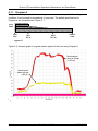
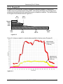
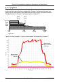
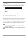
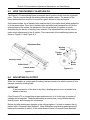
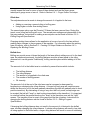
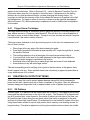
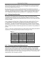
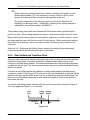
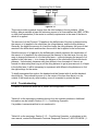
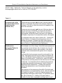
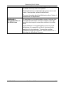
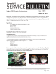
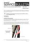
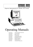
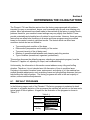
Section 6 DETERMINING THE OILING PATTERN The Phoenix LT4 Lane Machine arrives from the factory preprogrammed with patterns intended for open or recreational, league, and tournament play as well as a cleaning only pattern. Minor adjustments have been made to the machine at the factory to perfect these patterns; therefore, your machine’s exact settings may vary slightly from default. These provide a desirable and playable lane oil pattern for most centers. However, there are many factors that can affect lane conditions in a center and these programs may be modified based on the center's needs to yield best results. The factors which can affect lane conditions include but are not limited to: Type and physical condition of the lanes Environment (temperature and humidity) of the center Type and viscosity of the oil being used Number of games bowled between each cleaning and oiling session Type of bowlers (recreational, organized, professional) This section discusses the default programs, selecting an appropriate program, how the Phoenix LT4 applies oil, adjusting oil output, and troubleshooting. Unfortunately, the information in this section cannot address every oiling and buffing situation. Therefore, it is not intended as a full discussion of how to condition lanes. Factoring in the center’s bowlers, lanes, environment, and choice of oil, the machine has multiple possible adjustments, such as wicking foams and oiling/buffing distances, that can help achieve the ideal oil pattern. The factory programs will work in the vast majority of centers, without additional adjustments. 6.1 DEFAULT PROGRAMS In the following pages, each of the Phoenix LT4's factory programs is explained in detail. Included, is a graphic depiction of the processes the machine will perform on the lane and a typical graph of the oil pattern. A legend for the illustration of the programs is shown in Table 6- 1. Operation Table 6- 1 Symbol Cleaning Conditioning Buffing 61-900040-000 Rev. Date: 12/12 6-1 Phoenix LT4 Lane Machine Operations, Maintenance, and Parts Manual 6.1.1 Program A Program A is a single pass oil pattern that gives novice bowlers a predictable bowling condition. It can be used for recreational or open play. The default specifications for Program A are shown below in Figure 6- 1. First Pass Foul Line 14 ft 4.3 m 40 ft 12.2 m End of Lane Figure 6- 1 Figure 6- 2 shows a graph of a typical pattern applied to the lane using Program A. Measurement taken at 38 feet (1140 cm) Measurement taken at 8 feet (240 cm) Figure 6- 2 6-2 Rev. Date: 12/12 61-900040-000 Determining The Oil Pattern 6.1.2 Program B Program B is a double pass oil pattern designed for amateur leagues or clubs whose bowlers may have performance bowling balls. It will protect the lanes from damage due to performance bowling balls while providing a more competitive condition. The specifications for Program B are shown below in Figure 6- 3. 9 ft 2.7 m 20 ft 6.1 m Second Pass First Pass Foul Line 18 ft 5.5 m 40 ft 12.2 m End of Lane Figure 6- 3 Figure 6- 4 shows a graph of a typical pattern applied to the lane using Program B. Measurement taken at 38 feet (1140 cm) Measurement taken at 8 feet (240 cm) Figure 6- 4 61-900040-000 Rev. Date: 12/12 6-3 Phoenix LT4 Lane Machine Operations, Maintenance, and Parts Manual 6.1.3 Program C Program C is a double pass oil pattern designed for tournaments and leagues whose bowlers will use high performance bowling balls. Program C will protect the lanes from damage due to performance bowling balls while providing a highly competitive condition. The specifications for Program C are shown below in Figure 6- 3. 15 ft 4.6 m 27 ft 8.2 m Second Pass First Pass Foul Line 25 ft 7.6 m 42 ft 12.2 m End of Lane Figure 6- 5 Figure 6- 6 shows a graph of a typical pattern applied to the lane using Program C. Measurement taken at 40 feet (1200 cm) Measurement taken at 8 feet (240 cm) Figure 6- 6 6-4 Rev. Date: 12/12 61-900040-000 Determining The Oil Pattern 6.1.4 Program D Program D is a cleaning only pass as shown in Figure 6- 7. It will not add any oil to the lane and can be used to test the cleaning function of the machine or prepare the lane for inspection. First Pass Foul Line End of Lane Figure 6- 7 Program D will not add any oil to the lane; therefore no oil graph is needed to represent it. 6.2 SELECTING A PROGRAM FOR USE The program that best suits the bowling center will be largely dictated by the centers' customers. Program A should be used when the majority of the customers are recreational bowlers who bowl occasionally and use house balls. If a significant portion of the centers business comes from amateur bowling clubs or leagues whose bowlers use high performance bowling balls, Program B should be used. In either event, the oil pattern must be examined after a bowling session to ensure there is enough oil to protect the lanes. There should still be oil in the head section of the lane. If no oil is present in the heads, more oil must be applied via higher flowing wicking foams or adding a second pass. NOTE The easiest way to add oil to the lane is to switch programs. If Program A is not providing enough oil, use Program B. If Program B isn't providing the desired amount of oil, use Program C. The oil pattern can be optimized for the center by using the techniques discussed in this section. 61-900040-000 Rev. Date: 12/12 6-5 Phoenix LT4 Lane Machine Operations, Maintenance, and Parts Manual 6.3 HOW THE PHOENIX LT4 APPLIES OIL The Phoenix LT4 uses wicking foams to transport the oil from the oil tank onto the oil transfer roller. The oil is moved through the wicking foams by capillary action. The density of the foams determines how much oil is moved in a given amount of time and space. As the name implies, the oil transfer roller transfers the oil to the buffer brush which applies the oil to the lane surface. Since the oil transfer roller and buffer brush transport the oil from the wicking foams to the surface, the placement of the oil on the lane (oil pattern) is mostly determined by the density of wicking foam selected. The adjustment bars can be used to make minor adjustments to the oil pattern. The components of the conditioning system are shown in Figure 6- 8 and Figure 6- 9. Adjustment Bars Wicking Foams Transfer Roller Wicking Foams Buffer Brush Buffer Brush Transfer Roller Figure 6- 9 Figure 6- 8 6.4 ADJUSTING OIL OUTPUT While the oil pattern is a major part of bowling, the lane needs to be oiled to protect it from damage caused by bowling balls. IMPORTANT If the head section of the lane is dry after a bowling session, more oil needs to be added to the lane. If the Phoenix LT4 is not applying an appropriate amount of oil to the lane, a number of settings can be adjusted. These include adding a second pass, using different density wicking foams, and changing the oil distance. Before and after making any changes to the oiling programs, it is best to measure the oil pattern with a Computer Lane Monitor®. Many federations and bowling associations will measure the centers oil pattern. If the center does not have a Computer Lane Monitor®, 6-6 Rev. Date: 12/12 61-900040-000 Determining The Oil Pattern visually inspect the lane for more or less oil than desired and use the finger smear technique to gauge more or less oil. Refer to Section 6.4.1 - Finger Smear Technique. Oiled Area Two adjustments can be made to change the amount of oil applied to the lane: Adding or removing a second oiling or buffing pass Using higher or lower flow wicking foams The second pass option runs the Phoenix LT4 down the lane a second time. During this transit, more oiling and buffing will occur. The second pass settings are independent of the first pass settings. Instructions for adding a second pass can be found in Section 3.2.2 – Editing Program Specifications. Changing wicking foams allows for the application of more or less oil to the lane without making major changes to the programs or the machine. For information about the wicking foam oil outputs, refer to Section 6.5 - Creating Oil Output Patterns or Section 4.4.3 – Replacing the Wicking Foams. Buffed Area Buffing can provide more oil down the length of the lane without adding more oil in the head area. As mentioned previously, the buffing distance must be at least equal to the oiling distance but it can be greater. Additionally, buffing can take place without adding oil to the lane. The amount of oil in the buffed area is controlled by several factors which include: The buffing distance The oiling distance The amount of oil applied in the oiled area The number of buffing passes Oil viscosity The amount of oil at the end of the oiled area can be increased or decreased by lengthening or shortening the oiling distance. A longer buff-only area will create an area where the amount of oil on the lane gradually decreases (the ball will gradually start to hook past the transition). By eliminating or using a very short buff only zone, a sharp edge can be created (the ball will "snap" or start hooking immediately at the transition). It is important to note that neither the gradual hook nor the "snap" at the transition zone are the "right" answer. The transition zone is a part of the game just like the oil pattern. Instructions for changing the buffing distance can be found in Section 3.2.2 – Editing Program Specifications. If changing the buffing distance does not result in the amount of oil desired in the buffed area, consider changing the oiling distance. A shorter oiling distance will result in less total oil being applied to the buffed area; a longer oiling distance will result in more oil total being 61-900040-000 Rev. Date: 12/12 6-7 Phoenix LT4 Lane Machine Operations, Maintenance, and Parts Manual applied in the buffed area. Refer to Section 6.5.4 – Head to Backend Transition Zone for information about how the oil is applied in the buffed area. If adjustments to the buffing distance do not yield the desired results, consider changing the wicking foams. It is important to note that the viscosity of the oil also affects the amount of oil applied to the oiled and buffed areas. If a higher or lower oil viscosity is chosen over the type that was shipped with the Phoenix LT4, it will be necessary to experiment in order to find the best configuration for the center 6.4.1 Finger Smear Technique The finger smear technique is a technique used to gauge the amount of oil at any length on the lane, without access to a Computer Lane Monitor®. This will allow for a visual inspection of the lane for more or less oil than desired. Though it is not as accurate as using a Computer Lane Monitor®, this method can be effective. The finger smear technique is done by choosing a point on the lane for measurement of oil. Here is how it’s done: Place finger at the very edge of the lane bordering the gutter. Push finger forward and downward at approximately a 45° angle, through the oil, toward the center of the lane. This motion pushes the oil up at the edges of the line that was made in the oil. You should look for the size of oil puddle displaced by the finger motion while also feeling for slight changes in resistance to the motion. Areas with more oil will allow for an easier finger slide and more oil to be displaced. Areas that are too dry will resist finger motion. This test is especially good for verifying oil at a point on the lane where, at first glance, there doesn’t appear to be any. Some synthetic lanes have a tendency to appear dry when there is a very small amount of oil on them. 6.5 CREATING OIL OUTPUT PATTERNS While lane oil was first used to protect against damage caused by friction between the lanes and the ball, it has evolved into a major component of the game. Often the difference between happy and disgruntled club or league bowlers is the oil pattern they bowl on. 6.5.1 Oil Patterns Different types of oil patterns can be created with the Phoenix LT4 by changing the wicking foams and the adjustment bars on the top of the oil tank. The Phoenix LT4 is shipped with two #10 (medium-low) output foams for the outside 8 inches on both sides of the lane, two #6 (medium-high) foams along the next three inches (the track) on each side of the lane, and two #4 (super-high) output foams (10 inches each) for the middle 20 inches of the lane. Using these foams creates a top-hat style pattern that is used by most bowling centers for league bowling. This pattern applies less oil along the outsides and more down the middle. 6-8 Rev. Date: 12/12 61-900040-000 Determining The Oil Pattern While different environmental conditions, such as temperature and humidity, between the factory and bowling center can alter the amount of oil applied, the overall pattern profile should remain approximately the same. By using wicking foams of various densities along the 42 inch width of the oil tank, the Phoenix LT4 can apply numerous oiling patterns. Mixing and matching wicking foams and varying the adjustment bars will allow for a large number of oil patterns. Refer to Section 4.4.3 – Replacing the Wicking Foams and Section 4.3.9 – Adjusting the Oil Tank Bars. 6.5.2 Wicking Foam Densities The Phoenix LT4 is shipped with six wicking foams made of three different densities. Changing wicking foam types can result in significant changes to the amount of oil being applied to the lane, while adjusting the adjustment bars on the top of the oil tanks will result in smaller changes. A set of replacement wicking foams of different densities was supplied with the Phoenix LT4 Lane Machine. Each density of wicking foam is printed with a number for easy identification. The higher the number printed on the foam, the higher the foam’s density, and therefore the lower the oil output. Having different density foams as well as having the ability to change the location of each foam type allows for the creation of many different oil patterns. Table 6- 2 shows the correlation between the number printed on the wicking foam and the comparative oil output along with the part number of each type of foam. Table 6- 2 Output Super-High High Medium-High Medium Medium-Low Low Extra-Low Super-Low Foam Density #4 #5 #6 #8 #10 #11 #12 #13 Part Number 294-115-490 294-115-488 294-115-486 294-115-484 294-115-482 294-115-652 294-115-653 294-115-654 6.5.3 Preparing Custom-Sized Wicking Foams Replacement wicking foams come in lengths of 48 inches. When cutting a replacement foam section, try to make the cut as clean and as straight as possible. Using a straight edge as a guide and a new blade in the cutter will help prevent jagged edges and gaps between foam sections and in the pattern. One trick is to slightly overlap two foams keeping their top edges aligned, and make a single cut through both of them. The resulting cut will match perfectly, even if its angle is a little off. 61-900040-000 Rev. Date: 12/12 6-9 Phoenix LT4 Lane Machine Operations, Maintenance, and Parts Manual TIP When cutting new wicking foams from a section of factory bulk length, cut and discard approximately 1/2" from the factory cut edge. Failure to do so could result in inconsistent oil flow through the wicking foam at the end. The proper dimensions of the wicking foams can be found in Section 4.4.3 – Replacing the Wicking Foams. Additionally, a wicking foam cutting template is available for order as part number 294-080-201. The outside wicking foams that were shipped with the machine have a profiled edge to prevent oil drips. When cutting replacement foams; cut the same profile in the new foam. Before inserting the wicking foams into the machine, align them on a flat surface to ensure the edges and top meet, and that they total 42 inches across. When inserting the wicking foams into the oil tank tray, start at one side and insert the wicking foams across to the other side. Section 4.4.3 – Replacing the Wicking Foams contains the wicking foam replacement procedure as well as the dimensions for each of the foams. 6.5.4 Head to Backend Transition Zone When the oiling operation is selected, oiling will begin at the foul line and end at the distance specified in the program. The buffer brush can be stopped where oiling ends or it can continue to buff past oiling distance. The difference between the oiling and buffing distances is called the buff-out area. This area can have a major impact on how the bowling ball reacts with the oil pattern. If the lane is not buffed past the oiling distance, a sharp break between the oiled and dry surfaces is created. If the Phoenix LT4 continues to buff, the remaining oil in the brush will be applied to the lane until the buffer brush runs dry or reaches the end of the buffing area. The amount of oil will gradually decrease in both length and slightly in width as the machine buffs down the lane. If a top-hat style oiling pattern is being used, the buff-out area will look similar to Figure 610 on this page and Figure 6- 11 on the next. Foul Line Oiling Buffing Stops Stops Transition Zone Figure 6- 10 6-10 Rev. Date: 12/12 61-900040-000 Determining The Oil Pattern Foul Line Oiling Buffing Stops Stops Figure 6- 11 This zone provides a gradual change from the oiled surface to the dry surface. When buffing, always maintain at least the minimum amount of oil that satisfies the USBC, WTBA, or other local association (if the center is certified) requirements in the area of the lane to which oil is applied. The amount of oil the Phoenix LT4 applies to the buffed area of the lane is determined by the amount of oil applied to the oiled area, the oiling distance, and the buffing distance. Generally, the higher the amount of oil and the longer the oiling distance, the more oil that remains in the buffer brush and therefore the more oil that is applied in the buffed area. Since the amount of oil applied to the buffed area is directly related to the combination of the amount of oil applied in the oiled area and the distance of the oiled area, the only two ways to change the amount of oil in the buffed area — without changing the amount of oil applied to the oiled area — is to change the distance of the oiled area or the buffer brush pressure. Unfortunately, because every lane differs in how it accepts oil, there is no formula for determining how long to set the oiling distance to get a given amount of oil taper in the buffed area. It will be necessary to experiment with different oiling distances to find the right settings for the center. To briefly summarize this section, the heads should be flooded with oil and the backend should be dry. There should be more oil in the center of the lane than there is on the outside. If the heads are dry after bowling, more oil is needed to protect the lane. 6.5.5 Troubleshooting A number of factors can affect the oil pattern and its application to the lane. Table 6- 3 on the next page contains solutions for a few common problems. Additional information can be found in Section 5.1.3 – Conditioning Operation. If a problem is encountered that is not mentioned in Table 6- 3 on the next page, Section 5.1.3 – Conditioning Operation, or elsewhere in this user manual, contact the Brunswick Customer Response Center at 1-800-YES-BOWL (161-900040-000 Rev. Date: 12/12 6-11 Phoenix LT4 Lane Machine Operations, Maintenance, and Parts Manual 800-937-2695). Additionally, Technical Support can be reached by e-mail at [email protected] or via fax at 1-231-725-4667. Table 6- 3 Dry spots in the oiled area (from depressions, undulating lane surfaces, etc.) If there are some dry spots but the rest of the lane has the amount of oil desired, the buffer brush pressure should be increased. This will not affect the amount of oil applied in the rest of the oiled area. If there are some dry spots and the rest of the lane does not have the amount of oil desired, a second pass should be added to the oiling program. If there still is not enough oil being applied, the wicking foams may need to be replaced with higher output foams or increase the transfer roller speed. For information about this, refer to Section 6.5 - Creating Oil Output Patterns. If changing the wicking foams does not eliminate the problem, increase the buffer brush pressure. For information about checking and testing the buffer brush, refer to Section 4 - Maintenance and Adjustments. Washboard or Corrugated Pattern In The Oiled Area This indicates one of four things: the buffer brush pressure is not consistent across the lane, the oil output is too low, the buffer brush pressure needs to be increased, or the buffer brush has been contaminated with grease due to improper storage. Test the buffer brush pressure across the entire width of the brush. The pressure should be at the same point between B and C on the Buffer Pressure Adjustment Tool at each place tested on the buffer brush. If they are not, adjust the buffer brush pressure until the pressure is the same across the width of the brush. For information about measuring the pressure and adjusting the buffer brush pressure, refer to Section 4 Maintenance and Adjustments. Condition the lane after making the adjustments to see if the problem has been eliminated. If the pressure is the same across the width of the brush and the washboard or corrugated pattern occurs, check the amount of oil applied to the lane. If more oil is desired, replace the wicking foams with higher output foams. For information about this, refer to Section 6.5 - Creating Oil Output Patterns. Condition the lane after changing the wicking foams to see if 6-12 Rev. Date: 12/12 61-900040-000 Determining The Oil Pattern their oil output eliminates the problem. If the problem persists, the buffer brush may need to be replaced. If the brush has been contaminated with grease, remove and clean. If issue persists, replace the buffer brush. For more information about the buffer brush, refer to Section 4 Maintenance and Adjustments. Washboard or Corrugated Pattern In The Buffed Area If a washboard or corrugated pattern occurs in both the oiled area and the buffed area, correct the condition in the oiled area first which may also correct the condition in the buffed area. If the washboard or corrugated pattern occurs only in the buffed area, it is caused by too little oil in the brush after applying oil in the oiled area. To correct the condition, increase the buffer brush pressure. Refer to Section 4.3.1 – Adjusting the Buffer Brush Pressure. 61-900040-000 Rev. Date: 12/12 6-13