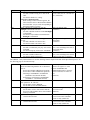
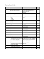
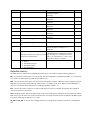
1
System Bit and Register Reference
Local memory
Local memory resides in DRAM and every value is initialized to zero at system start up.
The HMI is equipped with following local memory ranges:
LB 0000 ~ 9999 (Bit devices) Segmented in
groups of 16 bits as follows:
LW 0000 ~ 9999 (Word devices)
LW0
LW1
LW2
LB 15~0
LB 31~16
LB 47~32
….
….
LB 9983~9968
LB 9999~9984
LW9998
LW9999
Each LBnnnn is a 1-bit device and each LWnnnn is a 16-bit device. These devices use separate memory areas and do not
overlap (i.e. LB0000 is not the first bit of LW0000. Changing LB0000 does not affect LW0000).
Note: The Local Bit and Word addresses above 8999 are reserved for system use.
Remote memory
When using Master - Slave hardware configurations, the Slave HMIs can access the Master’s Local memory.
Master local memory ranges:
Ms_LB 0000 ~ 9999 (Bit devices) and Ms_LW 0000 ~ 9999 (Word devices).
Reserved Local Words/Bits
Some Local Words, Local Bits and Recipe Words are reserved for special purposes. Users should not use these areas
except for their specified purposes.
Local Bits: 9000~9999 are reserved
Local Words: 9000~9999 are reserved
Reserved Local Bits
LB Address Description
9000~9009 Initialized as ON
9010
9011
9012
9013
Recipe download indicator, it is:
Set ON when downloading
Set OFF when download done
Recipe upload indicator, it is:
Set ON when uploading
Set OFF when upload done
Recipe download/upload indicator, it is:
Set ON when transferring data
Set OFF when transfer done
Task bar Touch Indicator pressed bit, it is:
Set ON when Touch Indicator is pressed
NOTE
Use these bits for objects that need an
initial setting of ON. (read/write)
Use this bit to indicate when a recipe
download is in progress (read/write).
Use this bit to indicate when a recipe
upload is in progress. (read/write)
Version
ver 1.2
ver 1.2
ver 1.2
Use this bit to indicate when any recipe ver 1.2
transfer is in progress. (read/write)
This bit does not return the state of the Ver 1.4
”touch indicator”. (read/write)
LB Address Description
9014
Task bar CPU Indicator pressed bit, it is:
Set ON when CPU Indicator is pressed
9015
Task bar Alarm Indicator pressed bit, it is:
Set ON when Alarm Indicator is pressed
9016
Print Error indicator:
Changes to 1 when printing fails
9017
9020
9021
9022
9030
9031
9032
9040
9041
9042
9043
9044
9045
9046
Printer enable bit. The user:
Sets ON to disable print functions.
Sets OFF to enable print functions.
Pen enable bit. The user:
Sets ON to enable pen functions.
Brush (Eraser) enable bit. The user:
Sets ON to enable brush functions.
Clipping enable bit. The user:
Sets ON to enable clip functions.
Pen width to 1 pixel enable bit. The user:
Sets ON to set pen width to 1 pixel.
Pen width to 2 pixels enable bit. The user:
Sets ON to set pen width to 2 pixels.
Pen width to 3 pixels enable bit. The user:
Sets ON to set pen width to 3 pixels.
Fast Selection window enable bit. The user:
Sets ON to hide Fast Selection window.
Sets OFF to show (pop-up) Fast Selection
window.
Task Bar enable bit. The user:
Sets ON to hide the Task Bar.
Sets OFF to show (pop-up) the Task Bar.
Task Buttons enable bit. The user:
Sets ON to hide the two Task Buttons.
Sets OFF to show (pop-up) the two Task
Buttons.
Hide/Show Task Items (Fast Selection screen, Task
Bar and Task Buttons) The user:
Sets ON to hide the Task Items.
Sets OFF to show (pop-up) the Task Items.
Enable changes made to System Parameters in
Retentive memory area. The user:
Sets ON to make the Security Passwords,
Backlight and Buzzer System Parameters
active.
OFF has no effect.
Reset HMI. The user:
Sets ON to reset the HMI.
Security level change event indicator.
NOTE
This bit does not return the state of the
”CPU indicator”. (read/write)
This bit does not return the state of the
”alarm indicator”. (read/write)
Use to trigger an alarm or event to let
the user know there is a problem with
printing. (read only)
Setting in System Parameters must
have a printer selected for this Bit to
have an effect. (read/write)
Positive edge trigger. Message board
use (read/write)
Positive edge trigger. Message board
use (read/write)
Positive edge trigger. Message board
use (read/write)
Positive edge trigger. Message board
use (read/write)
Positive edge trigger. Message board
use (read/write)
Positive edge trigger. Message board
use (read/write)
This bit overrides the System
Parameter Task Bar setting.
(read/write)
Version
Ver 1.4
Ver 1.4
Ver 1.4
Ver 1.4
Ver 1.4
Ver 1.4
Ver 1.4
Ver 1.4
Ver 1.4
Ver 1.4
Ver 1.4
Task Bar control (read/write)
Ver 1.4
Task Bar control (read/write)
Ver 1.4
When enabled, all items appear in their
activated state. Task Bar and Fast
Selection window are opened.
(read/write)
Forcing this bit ON restores Security
Passwords, Backlight and Buzzer
system parameters from Reserved
Retentive word area.
After restoration, the system sets this
bit OFF. (read/write)
Forcing this bit ON resets the HMI.
(write)
Changes to 1 when going from a lower
security level to a higher security level.
(read only)
Ver 1.4
Ver 2.1
Ver 2.1
Ver 2.1
LB Address
9050
9051
9052
9055
9056
Description
Toshiba T/C write enable bit. The user:
Sets ON to enable writing to T/C bits ON &
OFF.
Sets OFF to disable T/C writing.
T1/T1S user’s manual NOTE:
When writing to Timer/Counter registers, the
Timer/Counter’s device data should be added to
the written data. (2 bytes each, corresponding to
the Timer/Counter’s register)
Enable or Disable the touchscreen when the
Backlight is turned OFF. The user:
Sets ON to disable touchscreen when Backlight
is turned OFF.
Sets OFF to keep touchscreen enabled when
Backlight is turned OFF.
Write back enable PLC Control, Change window.
The user:
Sets ON to disable write back to PLC.
Sets OFF to enable write back to PLC.
Disconnect action – PLC communications. The user:
Sets ON to continuously retry any write to PLC
command.
Sets OFF to stop any write to PLC commands.
Disconnect action –Touchscreen The user:
Sets ON to enable touchscreen.
Sets OFF to disable touchscreen.
NOTE
When setting the Timer/Counter‘s
device to ON, use ‘01’; for OFF use
‘00’. (read/write)
Version
Ver 1.5
OFF is the default mode.
(read/write)
Ver 1.6
This applies to Change Window
control only.
(read/write)
Ver 1.6
When HMI is disconnected from the
PLC, it acts according to the state of
this local bit 9055.
(read/write)
When HMI is disconnected from the
PLC, it acts according to the content
of this local bit 9056. (read/write)
Ver 1.6
Ver 1.6
Bits LB9060 ~ 9069, 6080 and 6081 are used for detecting Numeric Input Extend and ASCII Input Extend presses. See
the following page for Touchscreen map.
9070
9071
9090
9091
9092
MITSUBISHI J2-S10 driver control
Effects local data being added to ‘R’ or subtracted
from ‘R’.
Set bit ON to disable add/subtract operations
Set bit OFF to enable add/subtract operations
Valid range: 0x00800000 to 0x7FFFFFFF
(8388608 to 2147483647 decimal)
Invalid range: 0xFF799999 to 0x80000000
(-8388608 to –2147483648 decimal).
MITSUBISHI J2-S10 driver control
Write options for ‘R’. The user:
Sets bit ON to write to EPROM.
Sets bit OFF to write to RAM.(default)
Event Log Clear The user:
Sets bit ON to write to clear entries from the
Event Log. This includes entries stored in RW
memory, if enabled.
Adjusts contrast lighter one shade. The user:
Sets bit ON to activate.
Adjusts contrast darker one shade. The user:
Sets bit ON to activate.
Due to the protocol limitation of J2S100 for ‘R’ registers. A value
between 0x00800000 and
0xFFFFFFFF(inclusive) cannot be
written to R because it creates an
error.
(read/write)
Ver 1.6
(read/write)
Ver 1.6
After the Event log is cleared, this bit Ver 2.5.2
auto resets to OFF.
(read/write)
After the contrast is made lighter, this Ver 2.6.0
bit auto resets to OFF. Hardware
Version 4.5 only.(read/write)
After the contrast is made darker, this Ver 2.6.0
bit auto resets to OFF. Hardware
Version 4.5 only.(read/write)
LB Address
9100~9227
Description
PLC address/node communication status.
OFF: Communications timed out
ON: Communications are good
9228~9355
AUX address/node communication status
OFF: Communications timed out
ON: Communications are good
9360
CF status
OFF: CF not installed
ON: CF installed
Controls CF card Recipe download
ON to OFF: stops download action
OFF to ON: starts recipe download from CF
9361
9060
9061
9062
9063
9064
9065
9066
9067
9068
9069
9080
9081
Keypad control bit, left side (of window)
Bit forced ON whenever a user actives an input
data object (NI or AI).
Bit forced OFF when entering valid data or ESC
key is pressed.
Keypad control bit, left side
Keypad control bit, left and top side
Keypad control bit, left and bottom side
Keypad control bit, right side
Keypad control bit, right side
Keypad control bit, right and top side
Keypad control bit, right and bottom side
Keypad control bit, all side
Keypad control bit, all side
Keypad control bit, top side
Keypad control bit, bottom side
NOTE
These bits correspond to the PLC
Station Numbers 0~127. The
corresponding bit changes to 0 when
communication times out. Write 1 to
resume communications. (read/write)
These bits correspond to the AUX.
Station Numbers 0~127. The
corresponding bit changes to 0 when
communication times out. Write 1 to
resume communications. (read/write)
(read only)
Version
Ver 2.6.0
Ver 2.6.0
Ver 2.7.0
After recipe download, LB9361 stays Ver 2.7.0
ON until CF card is unplugged.
(read/write)
User can use this bit to control a
Direct window Keypad popup.
Keypad window is closed if input
succeeds.
(read only)
See note for 9060. (read only)
See note for 9060. (read only)
See note for 9060. (read only)
See note for 9060. (read only)
See note for 9060. (read only)
See note for 9060. (read only)
See note for 9060. (read only)
See note for 9060. (read only)
See note for 9060. (read only)
See note for 9060. (read only)
See note for 9060. (read only)
Ver 1.6
Ver 1.6
Ver 1.6
Ver 1.6
Ver 1.6
Ver 1.6
Ver 1.6
Ver 1.6
Ver 1.6
Ver 1.6
Ver 2.0
Ver 2.0
Reserved Local Words
LW Address Description
9000
Retentive memory Index base
9002-9003
Set to Numeric Input Maximum value
when numeric input gets the focus.
9004-9005
Set to Numeric Input Minimum value
when numeric input gets the focus.
9006
Message board mode
0: pen
1: brush
2: clipping
Pen width
0:1 pixel
1:2 pixel
2:3 pixel
Pen color
0-255
Local second
9007
9008
9010
9011
9012
9013
9014
9015
9016
9020
9034-9035
9040-9041
9042
9043
NOTE
RBI and RWI use this as an index offset when
accessing retentive data. (read/write)
Numeric Input loads its maximum value when
activated. When Numeric Input loses the
focus, it is set to zero.
(read only)
Numeric Input loads its minimum value when
activated. When Numeric Input loses the
focus, it is set to zero.
(read only)
Message board use
(read)
Version
Ver 1.2
Message board use
(read)
Ver 1.4
Message board use
(read/write)
BCD code, valid values: 0 ~ 59
(read/write allow)
BCD code, valid values: 0 ~ 59
Local minute
(read/write allow)
BCD code, valid values: 0 ~ 23
Local hour
(read/write allow)
BCD code, valid values: 1 ~ 31
Local day
(read/write allow)
BCD code, valid values: 1 ~ 12
Local month
(read/write allow)
BCD code, valid values: 0 ~ 9999
Local year
(read/write allow)
BCD code, valid values: 1 ~ 7
Local day of the week
(read/write allow)
If a screens object queue exceeds 1000, then
Object queue status
This holds the total number of objects of the HMI screen is too complex. The HMI is in
all the windows on the display.
danger of reporting a Severe System Error
(Each window can hold up to 500
due to low system resources.
objects.)
System time (unit as 0.1 second)
Starts at 0 when project started. (read/write)
Window Security password
Double word
This word must contain the password for (write only)
access to secure windows.
(read only)
Security level
The current active security level
A security level can only be forced to a lower
Force security level
Set to 0 (Lowest) or 1 (Middle).
level than is active. (write only)
Ver 1.4
Ver 1.4
Ver 1.4
Ver 1.4
Ver 1.2
Ver 1.2
Ver 1.2
Ver 1.2
Ver 1.2
Ver 1.2
Ver 1.2
Ver 1.4
Ver 1.4
Ver 1.6
Ver 1.6
Ver 1.6
LW Address Description
NOTE
This modification is to resolve a software
9044
Touch process mode
There are three operational modes to handle constraint in older versions.
momentary switches. They are based on the
current value of LW9044. Use a SET WORD When a momentary switch is pressed, (touch
down) the related bit is set ON.
of "Set on window open" in the Common
window to configure the desired operation
If there is any popup window that hides the
mode.
0: Window popup operation is enabled during momentary switch before it is released, the bit
remains ON even if released (touch up).
touch down and up, at touch up the BIT
(read/write)
previously set ON is set OFF, even if a
popup window hides the momentary
switch. (default initial value)
1: Window popup operation is disabled during
touch down and up.
2: Window popup operation is enabled during
touch down and up. Therefore, if the
momentary switch is hidden by a popup
window, on touch up, the BIT is not reset.
9050
Slave HMI can use this word to show the
Base Window Id
same screen as the Master.
9051
Reserved for Base Window ID write back
PLC control/Change screen writes back to
operations by a slave HMI. (See LW9050)
9051, so it is reserved for that purpose.
9054
Report printout option, print out:
Use this to change the attributes of a PLC
0: Text, Meters and Trends
Control/ Report printout assignment.
1: Text, Meters, Trends and Shapes but not (read/write)
patterns
2: Text, Meters, Trends and Bitmaps
3: Text, Meters, Trends, Bitmaps and
Shapes but not patterns
4: All
9055
Use this to offset window numbers coming
PLC Control word Offset
There are two options in the PLC Control from the PLC.
object that use this local word:
Example:
Change window, and Report printout.
A PLC Control / Change window uses D10.
The value in this word is added to the
If (LW9055) = 10, and D10 = 4 then the HMI
controlling data as an offset.
changes to window 14. After changing, the
Before writing back, the HMI subtracts
HMI writes back 4 to D11.
this value from the data.
(read/write)
9057
EventLog DataBase Item size Management Use when storing the Event Log in retentive
information, the size of every item
memory. (read only)
9058-9059
EventLog DataBase size
Use when storing the Event Log in retentive
Management information, the size of the memory.
DataBase, the size includes management (read only)
information. (total_item * item_size) +
(management_info_size)
9060-9075
Holds Numeric and ASCII Input, input data. (read/write)
9075 holds the least significant digits.
Version
Ver 1.6
Ver 1.2
Ver 1.2
Ver 1.5
Ver 1.6
Ver 2.1
Ver 2.1
Ver 1.4
LW Address Description
9080-9085
Project name
9086-9087
Project size in bytes
9088-9089
Project size in K bytes
9090-9091
Compiler version ID
9092
Project Compile Date/Year
9093
Project Compile Date/Month
9094
Project Compile Date/Day
9100
Indirect Addressing, For external PLC
only
Indirect Addressing, For external PLC
only
Language control word
9101
9130
9135
9136
NOTE
Use ASCII Data to show project name
It occupies 12 bytes.
(read only)
Use Numeric Data to show (In Decimal)
(read only)
Use Numeric Data to show (In Decimal)
(read only)
Use Numeric Data to show (In Decimal)
(read only)
Use Numeric Data to show (In Decimal)
(read only)
Use Numeric Data to show (In Decimal)
(read only)
Use Numeric Data to show (In Decimal)
(read only)
9100 indirect window number
Version
Ver 1.5
9101 indirect offset
Ver 1.6
Ver 1.5
Ver 1.5
Ver 1.5
Ver 1.5
Ver 1.5
Ver 1.5
Ver 1.6
Use this to change the displayed language
Ver 2.5
state for all labels. The range is 0~3.
(read/write)
Only displayed after download. Not available Ver 2.6.0
Li-Battery Voltage in millivolts
in Simulation modes. Hardware Version 4.5
Note: This is not the PLC’s battery. It is the only. The range is 0~1228 which is scaled
touchscreen’s internal battery.
from 0~3V. If the LW9135 < 1126 (2.75V),
change the Li-battery. (read only)
(read only)
Ver 2.7.0
CF card download status
0: inactive
1: download in progress
2: download complete
3: download failed
Retentive memory
The HMI units have 64K of battery backed RAM. This memory is accessed by using the following data types:
RB - accesses the first 2047 registers as 16 bit groups. The bit is designated as a hexadecimal number. (i.e. accessing bit
10 of word 63 would be Device type RB, Device address 63A)
RBI - accesses the first 2047 register’s bits and sets the index pointer to that bit. LW9000 is used in conjunction with the
RBI value to give an offset value for Recipe Transfer parts. (i.e. If RBI is set to device address 20 and LW9000 has a
value of 5 in it, then bit downloads and saves would begin at RB25 = RBI20 + 5.)
RW - accesses the retentive registers as words. The full range (0 to 65535) is available but registers above 60000 are
reserved for system use (See below).
RWI - Reads the register and sets the index pointer to the value in that register. LW9000 is used in conjunction with the
RWI value to give an offset value for Recipe Transfer parts. See Recipe Transfer Part for an example of the RWI register
is used. The valid range of RWI types is 0~ 32767.
Ms_RB and Ms_RW are used by Slave configured units for accessing retentive memory locations in a remote Master
unit.
NOTE: All retentive data types overlap in retentive memory. (i.e. changing RB0002 to ON changes the value of
RW00001. This also affects RWI00001 and RBI0002.)
Some Retentive Words are reserved for special purposes. Users should not use these areas except for their specified
purposes. Retentive Words: 60000~65535 are reserved
Reserved Retentive Word
RW Address Description
60000
Real Time Clock second
60001
Real Time Clock minute
60002
Real Time Clock hour
60003
Real Time Clock day
60004
Real Time Clock month
60005
Real Time Clock year
60006
Real Time Clock day of the week
NOTE
BCD code, valid values: 0 - 59
(read/write allow)
BCD code, valid values: 0-59
(read/write allow)
BCD code, valid values: 0-23
(read/write allow)
BCD code, valid values: 1-31
(read/write allow)
BCD code, valid values: 1-12
(read/write allow)
BCD code, valid values: 0-9999
(read/write allow)
BCD code, valid values: 1-7
(read/write allow)
Version
Ver 1.2
Ver 1.2
Ver 1.2
Ver 1.2
Ver 1.2
Ver 1.2
Ver 1.2
NOTE about RTC:
When using "Objects" to display and change system time, the user must take care to enter only valid values.
For example: Seconds cannot be changed to 78(BCD), if 78 (BCD) is entered, the RTC continues counting 78 79 80 ...
etc. This causes unpredictable conditions to happen.
System Information
System Parameter mapping to recipe card information. When a project is downloaded to a unit and run for the first time,
System Parameters are stored in the System Reserved Memory area. The following is a list of the mapping relationship.
Parameters from the General Tab
RW
System Parameter
60061
Back light saver
60064
Buzzer
Parameters from the Security Tab
RW
System Parameter
60071
Security Control:
60072
Password: level 0
60074
Password: level 1
60076
Password: level 2
NOTE
0 (Disable)
1~255 second (Enable)
0:None
1:Yes
Version
Ver 2.1
NOTE
0:None 1:Yes
two words
two words
two words
Version
Ver 2.1
Ver 2.1
Ver 2.`
Ver 2.`
Ver 2.1