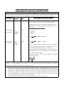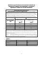
1
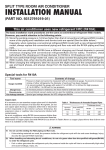
60C
CMS
CMS60C
Pulse Oximeter
CONTEC MEDICAL SYSTEMS CO., LTD
I
Instructions to User
Dear users, thank you very much for purchasing the Pulse Oximeter.
This Manual is written and compiled in accordance with the council directive MDD93/42/EEC for
medical devices and harmonized standards. In case of modifications and software upgrades, the
information contained in this document is subject to change without notice.
The Manual describes, in accordance with the Pulse Oximeter’s features and requirements, main
structure, functions, specifications, correct methods for transportation, installation, usage, operation,
repair, maintenance and storage, etc. as well as the safety procedures to protect both the user and
equipment. Refer to the respective chapters for details.
Please read the User Manual carefully before using this product. The User Manual which describes
the operating procedures should be followed strictly.Failure to follow the User Manual may cause
measuring abnormality, equipment damage and human injury. The manufacturer is NOT responsible
for the safety, reliability and performance issues and any monitoring abnormality, human injury and
equipment damage due to users' negligence of the operation instructions. The manufacturer’s
warranty service does not cover such faults.
Owing to the forthcoming renovation, the specific products you received may not be totally in
accordance with the description of this User Manual. We would sincerely regret for that.
This product is medical device, which can be used repeatedly.
WARNING:
� Uncomfortable or painful feeling may appear if using the device ceaselessly, especially for
the microcirculation barrier patients. It is recommended that the sensor should not be
applied to the same finger for over 2 hours.
� For the special patients, there should be a more prudent inspecting in the placing process.
The device can not be clipped on the edema and tender tissue.
� The light (the infrared is invisible) emitted from the device is harmful to the eyes, so the
user and the maintenance man should not stare at the light.
� Testee can not use enamel or other makeup.
� Testee
Testee’’s fingernail can not be too long.
� Please refer to the correlative literature about the clinical restrictions and caution.
� This device is not intended for treatment.
The User Manual is published by our company. All rights reserved.
II
Contents
1Safety
............................................................................................................................................................................
1Safety............................................................................................................................................................................
1
1.1Instructions for safe operations......................................................................................................................
1
1.2Warning.................................................................................................................................................................
1
1.3Attention...............................................................................................................................................................
1
2.Overvi ew
.....................................................................................................................................................................
ew.....................................................................................................................................................................
2
2.1Features.................................................................................................................................................................
2
2.2Major applications and scope of application.............................................................................................
2
2.3Environment requirements...............................................................................................................................
3
......................................................................................................................................................................
3.Principle
3.Principle......................................................................................................................................................................
3
4.Technical specifications
.........................................................................................................................................
specifications.........................................................................................................................................
3
4.1Main performance..............................................................................................................................................
3
4.2Main Parameters.................................................................................................................................................
4
5Installation
..................................................................................................................................................................
5Installation..................................................................................................................................................................
5
.....................................................................................................................................
5.1View of the front panel
panel.....................................................................................................................................
5
5.2Under side View and Left View..................................................................................................................
5
5.3Rear View............................................................................................................................................................
5
5.4Accessories...........................................................................................................................................................
6
.......................................................................................................................................................
6Operating Guide
Guide.......................................................................................................................................................
6
6.1Application method............................................................................................................................................
6
6.2Attention for operation...................................................................................................................................
11
6.3Clinical restrictions..........................................................................................................................................
11
7Maintain
transportation and storage
...........................................................................................................
7Maintain、transportation
storage...........................................................................................................
12
7.1Cleaning and Disinfecting.............................................................................................................................
12
7.2Maintain..............................................................................................................................................................
12
7.3Transportation and storage............................................................................................................................
12
.......................................................................................................................................................
8Troubleshooting
8Troubleshooting.......................................................................................................................................................
12
......................................................................................................................................................
9Key of Symbols
Symbols......................................................................................................................................................
13
10Function Specification ........................................................................................................................................
14
...................................................................................................................................................................
Appendix1
Appendix1...................................................................................................................................................................
16
...................................................................................................................................................................
Appendix2
Appendix2...................................................................................................................................................................
18
III
1 Safety
1.1 Instructions for safe operations
� Check the main unit and all accessories periodically to make sure that there is no visible
damage that may affect patient’s safety and monitoring performance about cables and transducers. It
is recommended that the device should be inspected once a week at least. When there is obvious
damage, stop using the device.
� Necessary maintenance must be performed by qualified service engineers ONLY. Users are not
permitted to maintain it by themselves.
� The oximeter cannot be used together with devices not specified in User’s Manual.Only the
accessory that appointed or recommendatory by manufacture can be used with this device.
� This product is calibrated before leaving factory.
1.2 Warning
� Explosive hazard—DO NOT use the oximeter in environment with inflammable gas such as
some ignitable anesthetic agents.
� DO NOT use the oximeter while the testee measured by MRI and CT.
� The person who is allergic to rubber can not use this device.
� The disposal of scrap instrument and its accessories and packings(including battery, plastic
bags, foams and paper boxes) should follow the local laws and regulations.
� Please check the packing before use to make sure the device and accessories are totally in
accordance with the packing list, or else the device may have the possibility of working abnormally.
� Please choose the accessories and probe which are approved or manufactured by the
manufacturer, or else it may damage the device.
� Please choose the battery chargers which should be ensured compliance with the requirements
of IEC 601-1, or else it may damage the device.
� The device can only be matched with the compatible probe.
� Please don't measure this device with functional tester for the device's related information.
1.
1.33 Attention
␇
Keep the oximeter away from dust, vibration, corrosive substances, explosive materials, high
temperature and moisture.
␇
If the oximeter gets wet, please stop operating it.
When it is carried from cold environment to warm or humid environment, please do not use it
␇
immediately.
␇
DO NOT operate keys on front panel with sharp materials.
␇
High temperature or high pressure steam disinfection of the oximeter is not permitted. Refer to
User Manual in the relative chapter (7.1)for instructions of cleaning and disinfection.
Do not have the oximeter immerged in liquid. When it needs cleaning, please wipe its surface
␇
with medical alcohol by soft material. Do not spray any liquid on the device directly.
␇
When cleaning the device with water, the temperature should be lower than 60℃.
␇
As to the fingers which are too thin or too cold, it would probably affect the normal measure
of the patients' SpO2 and pulse rate, please clip the thick finger such as thumb and middle finger
deeply enought into the probe.
1
␇
The pulse oximeter can be used to adult or infant. Whether the device is used to adult or
infant,it depends on the probe selected.
␇
The update period of data is less than 5 seconds, which is changeable according to different
individual pulse rate.
␇
Please read the measured value when the waveform on screen is equably and steady-going,
This measured value is optimal value. And the waveform at the monment is the standard one.
␇
If some abnormal conditions appear on the screen during test process, pull out the finger and
reinsert to restore normal use.
␇
The device has normal useful life for three years since the first electrified use.
␇
This device has the function of alarming, users can check on this function according to chapter
6.1 as a reference.
␇
The device has the function of limits alarming, when the measured data is beyond the highest
or lowest limit, the device would start alarming automatically on the premise of the alarming
function is on.
␇
The device has the function of alarming, this function can either be paused, or closed for good,
please check the chapter 6.1 as a reference.
␇
The device may not work for all patients. If you are unable to achieve stable readings,
discontinue use.
2.
Overview
The pulse oxygen saturation is the percentage of HbO2 in the total Hb in the blood, so-called the O2
concentration in the blood. It is an important bio-parameter for the respiration. A number of diseases
relating to respiratory system may cause the decrease of SpO2 in the blood, furthermore, some other
causes such as the malfunction of human body's self-adjustment, damages during surgery, and the
injuries caused by some medical checkup would also lead to the difficulty of oxygen supply in
human body, and the corresponding symptoms would appear as a consequence, such as vertigo,
impotence, vomit etc. Serious symptoms might bring danger to human's life. Therefore, prompt
information of patients' SpO2 is of great help for the doctor to discover the potential danger, and is of
great importance in the clinical medical field.
The Pulse Oximeter features in small volume, low power consumption, convenient operation and
being portable.It is only necessary for patients to put one of his fingers into a probe for diagnosis,
and a display screen will directly show the measured value of pulse oxygen saturation with the high
veracity and repetition.
2.1 Features
A. Operation of the product is simple and convenient.
B. The product is small in volume, light in weight and convenient in carrying.
C. Low power consumption
2.2 Major applications and scope of application
The Pulse Oximeter can be used in measuring the pulse oxygen saturation and pulse rate through
finger. The product is suitable for being used in family, hospital, oxygen bar, community healthcare,
physical care in sports (It can be used before or after doing sports, and it is not recommended to use
the device during the process of having sport) and etc.
2
The problem of overrating would emerge when the patient is suffering from toxicosis
which caused by carbon monoxide, the device is not recommended to be used under this
circumstance.
2.3 Environment requirements
Storage Environment
a) Temperature :-40℃~+60℃
b) Relative humidity :5%~95%
c) Atmospheric pressure :500hPa~1060hPa
Operating Environment
a) Temperature:10℃~40℃
b) Relative Humidity :30%~75%
c) Atmospheric pressure:700hPa~1060hPa
3.
Principle
Principle of the Oximeter is as follows: An experience formula of data process is established taking
use of Lambert Beer Law according to Spectrum Absorption Characteristics of Reductive
Hemoglobin (Hb) and Oxyhemoglobin (HbO2) in glow & near-infrared zones. Operation principle of
the device is: Photoelectric Oxyhemoglobin Inspection Technology is adopted in accordance with
Capacity Pulse Scanning & Recording Technology, so that two beams of different wavelength of
lights can be focused onto human nail tip through perspective clamp finger-type sensor. Then
measured signal can be obtained by a photosensitive element, information acquired through which
will be shown on screen through treatment in electronic circuits and microprocessor.
Figure 1.
4.
Technical specifications
4.1 Main performance
A. SpO2 value display
B. Pulse rate value display, bar graph display
C. Pulse waveform display
D. Low-voltage indication: low-voltage indicator appears before working abnormally which is due
to low-voltage
E. The display mode can be changed
F. Screen brightness can be changed
G. A pulse sound indication
3
H . With alarm function
I . With SpO2 value and pulse rate value of storage, the stored data can be uploaded to computers
J. It can be connected with an external oximeter probe
K . Real-time data can be transmitted to computers.
4.2 Main Parameters
A. Measurement of SpO2
Measuring range: 0%~100%
Accuracy:
When the SpO2 measuring range is 70%~100%,the permission of absolute error is ±2%;
below 70% unspecified
B. Measurement of pulse rate
Measuring range:30bpm~250bpm
Accuracy: ±2 bpm or ±2% (select larger)
C. Resolution
SpO2 : 1%, Pulse rate: 1bpm.
D. Measurement Performance in Weak Filling Condition:
SpO2 and pulse rate can be shown correctly when pulse-filling ratio is 0.4%. SpO2 error is ±4%,
pulse rate error is ±2 bpm or ±2% (select larger).
E. Resistance to surrounding light:
The deviation between the value measured in the condition of man-made light or indoor natural light
and that of darkroom is less than ±1%.
F. Power supply requirement: : 3.6 V DC ~ 4.2V DC.
G. Optical Sensor
Red light (wavelength is 660nm,6.65mW)
Infrared (wavelength is 880nm, 6.75mW)
H. Adjustable alarm range:
SpO2 : 0%~100%
Pulse Rate: 0bpm~254bpm
4
5 Installation
5.1 View of the front panel
Figure 2. Front View
5.2 Underside View and Left View
Finger 3. Underside View and Left View
1. Probe jack : It is used to connect a SpO2 sensor to measure the oxygen saturation and pulse rate.
2. USB port :It is used to connect a personal computer to export the trend data(or real-time data) or
charge the lithium battery via a data line.
5.3 RearView
Finger 4. RearView
(Refer to Figure 4 and insert the lithium battery properly in the right direction. )
5
5.
5.44 Accessories
A.
B.
C.
D.
E.
F.
A lithium battery(Model: GSP053759, rated voltage 3.7V, capacity1050mAh)
A User Manual
A power adapter
A data line
A disk (PC software)
An adult-oximeter probe(Model:CMS-03)
An infant-oximeter probe ( May purchase selectively)
6 Operating Guide
6.1 Application method
A.
a) Open the lid of battery box and put the battery in side, then close.
b) Put the suitable probe into the jack on the right side of the oximeter. (The probe is limited to be
produced by our company; never replace it with the similar ones by other manufacturers).
c) Put the finger into the probe.
d) Press the "power on/off button" long about a few seconds,the power is on,and the device will
start to self-inspect.The device displays the measuring interface after self-inspecting.
e) Do not shake the finger and keep the patient in a stable state during the process.
f) The data can be read directly from the screen on the measuring interface.
Fingernails and the luminescent tube should be on the same side.
If the alarm function is on
on,,the device will provide midium-priority alarm signal when
probe or finger is out 。 Intermittent alarm will occur and the user interface
"FINGER OUT".
Medium priority indicating that prompt operator response is required.
presents
Figure 5
(Actual probe may be different with the probe as figure 5,please accept the actual probe with the
device )
6
B.
Change display direction:
On the measuring interface, press the"screen change button"can change the display direction.
C.
Pause alarm:
a) Alarm including the alarm of measure data's going beyond the limits, the alarm of low-voltage,
the alarm of probe or finger's out of position.
b) When alarm is on,press the"alarm pause button"can pause the alarm,it can renew alarm in about
60s,and if pressing the"alarm pause button" Again with in 60s,it can renew alarm .
c) If you want to turn off the alarm for good, you should enter the menu for operation.
D.
Menu operations:
On the measuring interface,press the"menu button"can enter the menu of figure 6.Users can adjust
the setting through the main menu, such as alarm,pulse sound indication,backlight,data storage,data
transmission (with the use of data line),the specific method is as follows:
Figure 6. Main Menu Interface
a) Alarm setting
On the main menu interface,press the"up button"or"down button",move the menu choice bar to
"Alarm" ,then press the"menu button"to enter the alarm setting menu of figure 7:
Figure 7. Alarm Setting Menu
a.
The highest/lowest alarm limit setting
Press the"up button"or"down button"to choose the parameter to be adjusted, then press the"menu
button"again to enter the similar dialog box shown as figure 8,then press the"up button"or"down
button"to change data. Each press of the"up button"or"down button", the data will raise or descend
for one time accordingly, until it gets to the required number , then press the "menu button"for
another time to end the setting.
If the alarm function is on
on,, the device will provide midium-priority alarm signal when the
data of SpO2 or pulse rate is beyond the limit. Intermittent alarm will occur and the
7
measurement shows in yellow.
Medium priority indicating that prompt operator response is required.
When operating at the beginning, the operator inserts his finger, and setup the Spo2 ALM
HI lower than the current measured value, then the machine will start alarm. The pulse rate
alarm test is the same with the above.
Figure 8.
b.
The alarm state setting
Press the"up button"or"down button",move the menu choice bar to "Alarm",then choose the alarm
state (on/off) by pressing the "menu button", choose “on”to start the alarm function, and choose
“off” to close it for good.
b)
Pulse sound indication setting
On the main menu interface,press the"up button"or"down button",move the menu choice bar
to"Pulse Sound", then choose the pulse sound indication state (on/off) by pressing the "menu
button",press “on” to start the function, and press “off” to close it.
c) Backlight adjustment
On the main menu interface,press the"up button"or"down button",move the menu choice bar to
"Brightness",then press the"menu button"to change the number in order to adjust the brightness of
screen.
d)
Data storage setting
This device has the function of 24 hours data storage , it has the capability of accurately storing
pulse rate and SpO2 data, then transmit the data to computer with the data line for replay and
analysis.
a. On the main menu interface,press the"up button"or"down button",move the menu choice bar
to"Record",then press the"menu button"again to enter the dialog box of figure 9:if it is in recording
state,the"Stop"is displayed on menu;if it is not in recording state,the"Start"is displayed on menu.
Figure 9.
8
b. When the"Start"is displayed on the menu,if the memory still have the former data in storage ,the
" Do you really want to recover the memory" dialog box will be displayed when pressing the
"menu"button ,then press the"up button"or"down button"to choose setting,then press the"menu
button"to confirm setting,the dialog box will be displayed as figure 10:It needs to set the starting
time for data storage by users, users can change the setting value by pressing the"up button"or"down
button",and confirm the setting value by pressing the"menu button",the black cursor will move to
next place after setting.When the black cursor move to"Yes"(store) or "No"(don't store),press the"up
button"or"down button"to choose setting,then press the"menu button"to confirm setting.
c. When the"Stop"is displayed on menu,the"Do you really want to stop recording "dialog box
will be displayed when pressing the "menu button".then press the"up button"or"down button"to
choose setting,then press the"menu button"to confirm setting.
Figure 10.
d. If the data storage function is being turned on, when return to the measuring interface, a red
"REC"sign and a flashing red dot would appear on screen, which means the device is in a state of
storing.
e. In the state of storing, whatever interface the device is on (measuring interface, menu interface),
the sign "Recording" would appear on the screen in 30 seconds, and then the screen will be
automatically shut down. If pressing any button(power on/off excluded) at this moment, the sign
"Recording" would appear on the screen, and then the screen will be automatically shut down
again;if pressing the "power on/off button", the device would return to the former interface.
f. If turning on the data storage function, the former data storage will be automatically removed.
g.
In the state of data storing, after the screen is automatically shut down, the pulse sound
indication would be off for saving power.
h. When the storage space is full, it displays “Memory is full” on the screen, and then shut down in
a few seconds. But it will still display “Memory is full” by the next time you turn on the device on
the purpose of warning the user, if press any button(power on/off excluded) again, it will enter the
measuring interface.
e ) Stored data transmission setting
Firstly, please install the affiliated software into the computer, and then two icons would appear on
the desktop after installation. The icon of SpO2 is a program for receiving real-time data which is
shown as figure 11; the icon of SpO2 Review is a program for receiving stored data which is shown
as figure 12.
Figure 11.SpO2 program
9
Figure 12. SpO2 Review program
a. Please connect the device to computer with the affiliated data line , then double click"SpO2
Review"icon to start the program.
b. On the main menu interface,press the"up button"or"down button" in order to move the menu
choice bar to"Upload",then press the"menu button"to transmit the stored data to computer for replay
and analysis.
c. In the state of storing, it is not applicable for the users to upload the stored date to computer.
d. When the stored data is being uploaded ,the screen displays as figure 13.
Figure 13.
e. When the upload of stored data is finished, the device will automatically return to the main
menu, and the menu choice bar will move to "Exit"automatically as well.
f) Exit the main menu
On the main menu interface,press the"up button"or"down button" in order to move the menu choice
bar to"Exit",then press the"menu button"to exit the main menu.
E.
Real-time data transmission
a) Please connect the device with computer by the data line which is equipped with the device,then
double click "SpO2"icon to open"SpO2"program.
b)
The data can be displayed on computer screen in a few seconds.
c) When you unplug the data line from computer, there is a dialog box "Save data at view"
appearing on the desktop, in which you can input some patient's basic information.
F. Charge
There are two kinds of charging methods:
a)
Connect the device with computer by data line, then the device should be under charging state.
b) Connect the device with power supply by power adaptor, then the device should be under
charging state.
c)
The five status of battery power are shown as follows:
10
Power supply by battery only, and battery status is full
Battery status is not full
Battery status is draining away
Low power alarm indication(Please charge the battery )
the four status above shows
Battery is under charging
dynamically in turn
d ) When charging the battery in the state of power off, the sign of battery status still exists on the
screen, but it will disappear in about 60 seconds for saving power. However, the sign will appear
again if you press any button(power on/off excluded) at this moment.
If the alarm function is on
on,,the device will provide high-priority alarm signal when the
battery is in low power status .Intermittent alarm will occur and the battery icon turns red in
the state of flashing.
High priority indicating that immediate operator response is required.
6.2 Attention for operation
A.
Please check the device before using, and confirm that it can work normally.
B . The finger should be in a proper position (see the attached illustration of figure 3 for reference), or
else it may result in inaccurate measure.
C. The SpO2 sensor and photoelectric receiving tube should be arranged in a way with the subject’
s
arteriole in a position there between.
D. The SpO2 sensor should not be used at a location or limb tied with arterial canal or blood pressure
cuff or receiving intravenous injection.
E . Do not fix the SpO2 sensor with adhesive or else it may result in venous pulsation and inaccurate
measure of SpO2 and pulse rate.
F. Excessive ambient light may affect the measuring result. It includes fluorescent lamp, dual ruby
light, infrared heater, direct sunlight and etc.
G . Strenuous action of the subject or extreme electrosurgical interference may also affect the
accuracy.
H . Testee can not use enamel or other makeup.
I . Please clean and disinfect the device after operating according to the User Manual(7.1).
6.3 Clinical restrictions
A. As the measure is taken on the basis of arteriole pulse, substantial pulsating blood flow of
subject is required. For a subject with weak pulse due to shock, low ambient/body temperature,
major bleeding, or use of vascular contracting drug, the SpO2 waveform (PLETH) will decrease. In
this case, the measurement will be more sensitive to interference.
B . For those with a substantial amount of staining dilution drug (such as methylene blue, indigo
green and acid indigo blue), or carbon monoxide hemoglobin (COHb), or methionine (Me+Hb) or
11
thiosalicylic hemoglobin, and some with icterus problem, the SpO2 determination by this monitor
may be inaccurate.
C. The drugs like dopamine, procaine, prilocaine, lidocaine and butacaine may also be a major
factor blamed for serious error of SpO2 measure.
D. As the SpO2 value serves as a reference value for judgement of anemic anoxia and toxic anoxia,
some patients with serious anemia may also report good SpO2 measurement.
transportation and storage
7 M aintain
aintain、transportation
7.1 Cleaning and Disinfecting
Using medical alcohol to disinfect the device, nature dry or clean it with clean soft cloth.
7.2 Maintain
A.
Please clean and disinfect the device before using according to the User Manual(7.1).
B.
Please recharge the battery when the screen shows
.
C.
Recharge the battery soon after the over-discharge. The device should be recharged every six
months when it is no regular used. It can extend the battery life following this guidance.
D.
Please take out the batteries if the oximeter is not in use for a long time.
E. The device needs to be calibrated once a year (or according to the calibrating program of
hospital). It also can be performed at the state-appointed agent or just contact us for calibration.
7.3 Transportation and storage
A. The packed device can be transported by ordinary conveyance or according to transport contract.
The device can not be transported mixed with toxic, harmful, corrosive material.
B. The packed device should be stored in room with no corrosive gases and good ventilation.
Temperature: -40°C~60°C; Humidity: ≤95%
8 Troubleshooting
Trouble
Possible Reason
Solution
1. Place the finger properly and
The SpO2 and Pulse 1. The finger is not properly positioned.
try again.
Rate can not be 2. The patient’s SpO2 is too low to be 2. Try again; Go to a hospital for
displayed normally
detected.
a diagnosis if you are sure the
device works all right.
1. The finger is not placed inside deep
The SpO2 and Pulse
1. Place the finger properly and
enough.
Rate
are
not
try again.
2. The finger is shaking or the patient is
display
ed
stabl
y
displayed stably
2. Let the patient keep calm
moving.
1. Please recharge the battery
1. The battery is drained away or almost
2. Please Install the battery
The device can not drained away.
again.
ed on
be turn
turned
2. The battery is installed incorrectly.
3. Please contact the local service
3. The malfunction of the device.
center.
12
The display is off The battery is drained away or almost
suddenly
drained away .
Please recharge the battery
The device can not
1.The battery is not full charged.
be used for full time
2. The battery is broken
after charge
1. Please recharge the battery
2. Please contact the local service
center.
The battery can not
be full charged even
after
10
hours
charging time.
Please contact the local service
center.
The battery is broken
9 Key of Symbols
Signal
Description
Warning – See User Manual
The pulse oxygen saturation(%)
PRbpm
Pulse rate (bpm)
Close the alarm sound indication forever
Pause the alarm sound indication
Open the alarm sound indication
Close the pulse sound indication
Open the pulse sound indication
Power on/off
button
Alarm pause button/up button
Menu button
Screen change button/down button
Type BF
13
SN
Serial number
1. the finger clip falls off ( no finger inserted)]
2. Probe error
3. Signal inadequacy indicator
IPX1
Ingress of liquids rank
WEEE (2002/96/EC)
This item is compliant with Medical Device Directive 93/42/EEC of
June 14, 1993, a directive of the European Economic Community.
10 Function Specification
Information
Display Mode
The Pulse Oxygen Saturation(SpO2 )
2-digit digital
OLED display
Pulse Rate(PR)
3-digit digital
OLED display
Pulse Intensity (bar-graph)
bar-graph
OLED display
SpO2 Parameter Specification
Measuring range
0%~100%, (the resolution is 1%).
Accuracy
70%~100%:±2% ,Below 70% unspecified.
Calculate the Average value in every 4 measure value.
The deviation between average value and true value
does not exceed 1%.
Average value
Pulse Parameter Specification
Measuring range
30bpm~250bpm, (the resolution is 1bpm)
Accuracy
±2bpm or±2% (select larger)
Moving calculate the Average pulse rate every 4
cardio-beat, s cycle.
The deviation between average value and true value
does not exceed 1%
Average pulse rate
Safety Type
Interior Battery,BFType
Pulse Intensity
14
Range
Continuous bar-graph display, the higher display
indicate the stronger pulse.
Battery Requirement
Voltage 3.7 rechargeable lithium battery × 1
Batter
Batteryy working life
Charge and discharge no less than 500 times.
Adapter
Power
PowerAdapter
Input Voltage
100 to 240 VAC, 50/60 Hz
Output voltage
5 VDC
Output current
250mA
Output power
1.25 W
Oximeter Probe
Wavelength:660nm 880nm
Dimensions and Weight
Dimensions
87(L) × 45(W) × 22(H) mm
Weight
About 175 g (with the lithium battery*1)
15
Appendix 1
Guidance and manufacture
manufacture’’s declaration-electromagnetic emission
for all EQUIPMENT and SYSTEMS
Guidance and manufacture
manufacture’’s declaration –electromagnetic emission
The Pulse Oximeter(CMS60C) is intended for use in the electromagnetic environment specified below. The
customer of the user of the Pulse Oximeter(CMS60C) should assure that it is used in such an environment
Emission test
RF emissions
CISPR 11
compliance
Group 1
Electromagnetic environment-guidance
The Pulse Oximeter (CMS60C) uses RF energy only for its
internal function. Therefore, its RF emissions are very low
and are not likely to cause any interference in nearby
electronic equipment.
RF emissions
CISPR 11
Harmonic emissions
IEC 61000-3-2
Voltage fluctuations/
flicker emission
IEC 61000-3-3
Class B
The Pulse Oximeter(CMS60C) is suitable foe use in all
establishments, including domestic establishments and
those directly connected to the public low-voltage power
supply network that supplies buildings used for domestic
purposes.
Not applicable
Not applicable
Guidance and manufacture
manufacture’’s declaration-electromagnetic immunity
for all EQUIPMENT and SYSTEMS
Guidance and manufacture
manufacture’’s declaration-electromagnetic immunity
The Pulse Oximeter(CMS60C) is intended for use in the electromagnetic environment specified below. The
customer or the user of the Pulse Oximeter(CMS60C) should assure that it is used in such an environment
Electromagnetic
Immunity test
IEC60601 test level
Compliance level
environment
guidance
environment-guidance
Electrostatic
discharge (ESD) IEC
61000-4-2
±6KV contact
±8KV air
±6KV contact
±8KV air
Floors should be wood, concrete or
ceramic tile. If floor are covered
with synthetic material, the relative
humidity should be at least 30%.
Power
frequency
(50Hz) magnetic field
IEC 61000-4-8
3A/m
3A/m
Power frequency magnetic fields
should be at levels characteristic of
a typical location in a typical
commercial or hospital
environment
16
Guidance and manufacture
manufacture’’s declaration-electromagnetic immunity
for EQUIPMENT and SYSTEMS that are not LIFE-SUPPORTING
Guidance and manufacture
manufacture’’s declaration-electromagnetic immunity
The Pulse Oximeter(CMS60C) is intended for use in the electromagnetic environment specified below. The
customer or the user of the Pulse Oximeter(CMS60C) should assure that it is used in such an environment
Compliance
IEC60601
Immunity test
Electromagnetic environment -guidance
guidance
level
test level
Portable and mobile RF communication equipment should be
used no closer to any part of the Pulse Oximeter(CMS60C),
including cables, than the recommended separation distance
calculated from the equation applicable to the frequency of the
transmitter.
recommended separation distance
Conducted RF
IEC 61000-4-6
Radiated RF
IEC 61000-4-3
3Vrms
150kHZ to
80MHZ
3V/m
80MHz
2.5GHz
3Vrms
3V/m
to
⎡ 3.5 ⎤
d =⎢ ⎥ P
⎣ E1 ⎦
80MHz to 800MHz
⎡7⎤
d =⎢ ⎥ P
⎣ E1 ⎦
800MHz to 2.5GHz
Where P is the maximum output power rating of the transmitter
in watts (W) according to the transmitter manufacturer and d is
the recommended separation distance in meters (m).
Field strengths from fixed RF transmitters, as determined by an
electromagnetic site survey, a should be less than the compliance
level in each frequency range. b
Interference may occur in the vicinity of equipment marked with
the following symbol:
NOTE 1 At 80MHz and 800MHz, the higher frequency range applies.
NOTE 2
These guidelines may not apply in all situations. Electromagnetic propagation is affected by
absorption and reflection from structures, objects and people.
a
Field strengths from fixed transmitters, such as base stations for radio (cellular/cordless) telephones and land
mobile radios, amateur radio, AM and FM radio broadcast cannot be predicted theoretically with accuracy. To
assess the electromagnetic environment due to fixed RF transmitters, an electromagnetic site survey should be
considered. If the measured field strength in the location in which The Pulse Oximeter(CMS60C) is used
exceeds the applicable RF compliance level above, the Pulse Oximeter(CMS60C) should be observed to
verify normal operation. If abnormal performance is observed, additional measures may be necessary, such
as reorienting or relocating the Pulse Oximeter (CMS60C).
b
Over the frequency range 150 KHz to 80 MHz, field strengths should be less than 3V/m.
17
Recomme nde d se par atio n dis tanc e s be twe e n portab le and mobile RF
communica tions equipme nt and the EQU I P ME NT or SYSTE M for
EQUI P M EN T or SYSTE M that not LI FE -SUP P OR TI NG
Recommended separation distances between
portable and mobile RF communications equipment and the Pulse Oximeter(CMS60C)
The Pulse Oximeter(CMS60C) is intended for use in the electromagnetic environment in which
radiated RF disturbances are controlled. The customer or the user of the Pulse Oximeter(CMS60C)
can help prevent electromagnetic interference by maintaining a minimum distance between portable
and mobile RF communications equipment (transmitters) and the Pulse Oximeter (CMS60C) as
recommended below, according to the maximum output power of the communications equipment.
Rated maximum output
power of transmitter
(W)
Separation distance according to frequency of transmitter
(m)
80MHz to 800MHz
800MHz to 2.5GHz
⎡ 3.5 ⎤
d=⎢ ⎥ P
⎣ E1 ⎦
⎡7⎤
d =⎢ ⎥ P
⎣ E1 ⎦
0.01
0.1
0.1167
0.3689
0.2334
0.7378
1
10
1.1667
3.6893
2.3334
7.3786
100
11.6667
23.3334
For transmitters rated at a maximum output power not listed above, the recommended separation
distanced in meters (m) can be estimated using the equation applicable to the frequency of the
transmitter, where P is the maximum output power rating of the transmitter in watts (W) according to
the transmitter manufacturer.
NOTE 1 At 80MHz and 800MHz, the separation distance for the higher frequency range applies.
NOTE 2
These guidelines may not apply in all situations. Electromagnetic propagation is affected
by absorption and reflection from structures, objects and people.
Appendix 2
State
Low voltage alarm
Spo2 alarm
Alarm condition delay
1s
330ms
Alarm signal generation delay
20ms
20ms
Pulse rate alarm
Probe error alarm
330ms
16ms
20ms
20ms
18