1
GE Fanuc Automation
Programmable
Control Products
Series One’” PLC to
Series 90TM-30PLC
Translator
User’s Manual
GFK-0486
January,
1990
WARNINGS, CAUTIONS, AND NOTES AS USED IN THIS PUBLICATION
Warning notices are used in this publication to emphasize that hazardous voltages, currents, temperatures,
or other conditions that could cause personal injury exist in this equipment or may be associated with its
use.
In situations where inattention could cause either personal injury or damage to equipment, a Warning
notice is used.
i CAUTION
1
Caution notices are used where equipment might be damaged if care is not taken.
NOTE
Notes merely call attention to information that is especially significant to understanding and operating the
equipment.
This document is based on information available at the time of its publication. While efforts have been made to be accurate,
the information contained herein does not purport to cover all details or variations in hardware and software, nor to provide
for every possible contingency in connection with installation, operation, and maintenance. Features may be described herein
which are not present in all hardware and software systems. GE Fanuc Automation assumes no obligation of notice to
holders of this document with respect to changes subsequently made.
GE Fanuc Automation makes no representation or warranty, expressed, implied, or statutory with respect to, and assumes no
responsibility for the accuracy, completeness, sufficiency, or usefulness of the information contained herein. No warranties
of merchantability or fitness for purpose shall apply.
@Copyright
1990 GE Fanuc Automation
All Rights Reserved.
America,
Inc.
Contents
GFK-0486
1. Introduction
1
2. Unpack/Install
1
2.1. Packing List
1
2.2. Minimum
1
Requirements
2.3. Physical Description
1
2.4. Pre-Installation
1
Setup/Checkout
2.5. Installation
2
2.51. Floppy Disk Users
2
2.5.2. Hard Disk Users
2
2.6. Power Up/Verification
2
3. Setup
4. Operation
4.1. Main Menu
4.1.1. config
2
3
4
4
4.1.1.1. Specifying the Series One Configuration
4.1.2. Program
4.1.2.1. Math Functions
4.1.2.2. Results
4.1.3. Exit
5. Integration
6. System Considerations
6.1. Memory Usage
61.1. %M Memory
6.1.2. %T Memory
6.1.3. %R Memory
6.2. Algorithms Used
6.2.1. Timers and Counters
6.2.2. Sequencers
6.2.3. Shift Register
6.2.4. Math Functions
6.3. Programmer Intervention
SUBTRACT FUNCTION
ADD FUNCTION
DIVIDE FUNCTION
MULTIPLY FUNCTION
9
9
10
10
11
12
12
12
12
12
13
14
16
17
18
19
APPENDIX
A.
Sample Series One Original System
A-1
APPENDIX
B.
Series 90-30 System
B-l
Figures
iv
GFK-0486
Figure
Copyright and Disclaimer
Main Menu
CPU Selection Screen
Initial Rack Display
Discrete Input (DIN) Menu
Completely Specified Rack
%M Memory Usage by the Translator
%T Memory Usage by the Translator
%R Memory Usage by the Translator
3
4
5
6
6
7
10
11
12
1
Series One to Series 90130Translator
GFK-0486
1. Introduction
In order to minimize the effort and expertise required to move Series One PLC applications
90-30, GE Fanuc has developed this translator program.
to Series
Starting with a Logicmaster 1 print file of the original Series One program and the I/O module content
of each slot in the Series One system, the translator will determine the required 90-30 hardware, and
will convert the Series One program into a form usable by the Logicmaster 90-30 programming
package.
Logic translation should be nearly lOO%, but Series One Plus data operation (MATH) instructions will
To the maximum extent possible, the areas requiring attention are
require some manual intervention.
flagged by special coils.
The translator emulates the operation of the Series One Plus for the data
instructions, but programming efficiencies can generally be realized by changing the approach to the
application to take advantage of the instruction set of the 90-30 PLC.
This translator should be viewed as a tool which facilitates the conversion
final responsibility for system operation must be accepted by the user.
of the application,
but the
2. Unpack/Install
2.1. Packing List
The translator package
following files:
consists
of this manual
and a single 3 l/2 inch floppy
disk containing
the
3OXLAT.EXE
MODULES.DBA
EQUIV.DBA
KEYS.DBA
SAMPLE.TXT
2.2. Minimum Requirements
Workmaster
II, Workmaster
I, or other 100% IBM compatible.
256K RAM
One floppy disk drive (3.5”)
DOS version 2.0 or greater
The Distribution Diskette
Print file of the original application
from Logicmaster
1
Layout of the Series One system, ie. I/O modules by slot
Logicmaster
90-30 (Operation
requires a Hard Disk)
2.3. Physical Description
The translator is a software program
LIST above.
and requires no physical
2.4. Pre-Installation Setup/Checkout
There are no pre-installation
requirements.
description
other than the PACKING
Series One to Series 90-30 Translator
2
GFK-0486
2.5. Installation
2.5.1. Floppy Disk Users
The translator program may be executed from floppy disk. As always, you should make a working copy
of the original by using the DOS COPY command.
EXAMPLE: With the original diskette in drive
formatted diskette in drive b:, type
COPY
to make
A:*.*
your
a: and a
B:
working
copy
.
2.5.2. Hard Disk Users
Substantial performance improvement will be obtained by installing the program on a hard disk. First
create a directory (suggested name TRANSLAT) on the hard disk, and then copy all the files from the
distribution disk into that directory.
EXAMPLE: With the original diskette in drive
disk designated
c: type the following:
MKDIR
a: and a hard
C:\TRANSLAT
COPY A:*.*
C:\TRANSLAT
2.6. Power Up/Verification
In order to verify that the program files have been properly installed, default to the drive and directory
which contains the files from the distribution diskette
EXAMPLES:
A:
- for execution
from a floppy
disk
- for execution
from the hard
disk
c:
CD\TRANSLAT
then type
30XLAT
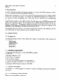
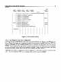
When the copyright and disclaimer screen (shown below) appears, you have properly completed the
installation.
If the screen does not appear, verify that all the files from the distribution diskette have
been copied into the operating directory.
3. Setup
The translator has no specific setup requirements
at this time.
Series One to Series 90-30 Translator
3
GFK-0486
4. Operation
In order to convert a Series One application to the 90-30 PLC, you must first copy the ASCII print file
from Logicmaster 1 into the same directory as the files from the distribution diskette. (NOTE: Programs
originally created using the Series One hand held programmer must first be imported into Logicmaster
1, conflicts resolved, and the ASCII print file created). In addition, you must know the Series One
hardware configuration, ie. the contents of each slot.
From the Copyright
and Disclaimer
screen, press any key to continue to the MAIN MENU.
a43756
SERIES 1 to SERIES 90-30 TRANSLATOR
SERIES 1 to SERIES 90-30 Translator
(Version 0.10)
Copyright 1989 by GE Fanuc Automation North America, Inc.
Published in only a limited, copyright sense and
all rights, including trade secret rights, are reserved.
Ge Fanuc-NA makes no representation or warranty, expressed, implied
or statutory with respect to, and assumes no responsibility for the
accuracy, completeness, sufficiency, or usefulness of the information
contained herein. No warranties of merchantibility or fitness for purpose
shall apply.
Press any key to continue.
Figure 1. Copyright and Disclaimer
Series One to Series 90-30 Translator
4
GFK-0486
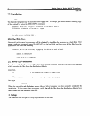
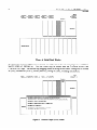
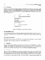
4.1. Main Menu
a43757
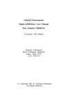
Main Menu
Program
Exit
Use arrow keys to highlight choice and RETURN to select.
Figure 2. Main Menu
The MAIN MENU screen is shown above in Figure 2. Operation of each selection will be discussed in
detail below. The SAMPLE file on the distribution diskette and the matching configuration in Appendix
I will be used to illustrate the operation. Tutorial instructions are shown in italics.
4.1.1. Config
This selection is used to specify the hardware configuration of the Series One system to be converted.
You will be prompted to specify a filename for the application. If the Series One print file is already on
disk, you should specify that filename, without extension. (Print files from Logicmaster 1 have a .txt
extension).
Press ENTER to select CONFIG and specify the filename SAMPLE.
Series One to Series 90-30 Translator
5
GFK-0486
a43758
1piT-l
21DOUT]
3p-7
4piiq
IOlaulT
s[AouTI
RACK 0
UL LISTED
Sl
JR 24Vdc
IC609SJRllO
Sl
JR 24 Vdc Sink In/Out
IC609SJR114
Sl
JR 24Vdc
Sink In/Out
IC609SJRl20
Sl
JR 24Vdc
Sink In, Relay Out
lC609SJRl21
Sl
JR 24 Vdc Source
IC609SJRl24
Sl
JR 24Vdc
IC6lOCPUl
Ox SERIES
ONE
Input/Output
Sink In, 11 W23OVac Out
ONE 10 SLOT
ONE PLUS 5 SLOT
SERIES 90-30
Out
5 SLOT
IC61 OCPUI Ox SERIES
IC61 OCPUI Oy SERIES
:RIES 1
In, Relay Out
Sink In/Relay
IC61 OCPUI Oy SERIES
ONE PLUS (slot 10 References
100-l 07)
L~LLLLLL’
lC61 OCPUI Oy SERIES
L
Sl JR 11 5Vac
IC609SJRlOl
IC609SJR102
ONE PLUS (slot 10 References
700-707)
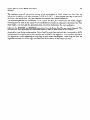
Figure 3. CPU Selection Screen
4.1.1.1.
Specifying
the Series One Configuration
Following selection of CONFIG from the main menu and specification of a filename, the CPU Selection
Screen (Figure 3) is displayed. A selection is made from the menu of possible Series One CPU’s by
using the CURSOR UP and CURSOR DOWN keys to highlight the appropriate item and pressing
ENTER. Once a selection has been made, a graphic representation of the Series One rack is displayed
on top of the screen, with a 90-30 rack displayed on bottom. (Note: if one of the Series One Junior
selections was made, several slots of the 90-30 will already have been filled in)
Referring to the SAMPLE configuration shown in Appendix A, notice that it uses the 5 slot Series One
CPU. Use the CURSOR DOWN key to highlight that selection and press ENTER.
6
Series One to Series 90-30 Translator
GFK-0486
a43759
10m
RACK 0
SERIES 1
SERIES 90-30
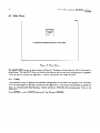
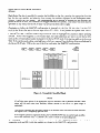
Figure 4. Initial Rack Display
If a Series One rack type CPU has been selected, one of the slots in the rack is highlighted (see INITIAL
RACK DISPLAY FIGURE 4). The slot cursor may be moved with the CURSOR RIGHT and
CURSOR LEFT keys. The function key mapping shown at the top of the screen corresponds to discrete
in (DIN), discrete out (DOUT), mixed (MIXED), analog in (AIN), or analog out (AOUT).
a43760
1
pi-1
2pq
3pi-J
4piir-l
5~1
lOpiF=1
RACK 0
CPU
SERIES 1
SERIES
IC610MDL106
24Vdc SINK INPUT,
D CONNECTOR,
IC610MDL107
24Vdc SINK INPUT,
REMOVABLE
IC61OMDLlll
24Vdc/ac
IC61OMDL112
24Vdc SOURCE
IC61OMDL125
115 Vat INPUT
IC610MDL129
115 Vat HIGH
IC6lOMDL127
230 Vat INPUT
SOURCE
LED (16 POINTS)
TERMINAL
BLOCK,
LED (16 POINTS)
INPUT
INPUT
{TERM
DENSITY
BLOCK)
(16 POINT)
(8 POINT)
LLLLLLLLL
Figure 5. Discrete Input (DIN) Menu
Series One to Series 90-30 Translator
7
GFK-0486
Each Series One slot is specified by moving the highlight to that slot, pressing the appropriate function
key for the type module, and selecting from among the modules displayed in the subsequent menu.
(Figure 5 shows the DIN menu). The corresponding 90-30 module is selected by the program and
placed in the 90-30 rack, and addresses are mapped between the systems. The Series One slots may be
specified in any order, but the 90-30 rack will always fill from left to right.
Continuing to follow the SAMPLE configuration in Appendix A, the first II0 slot (slot 2 in the CPU
rack) in the Series One was a discrete input (Press Fl - DIN). It was further an 8 point SINK INPUT
which happens to be the first menu item. Press ENTER to select it. If it had been another item, the
CURSOR UP and CURSOR DOWN keys would be used to highlight the selection before pressing
ENTER. Notice what happens: 1) the module type and octal addresses are shown in the Series One
rack; 2) the corresponding module is placed in the Series 90-30 rack; 3) its starting address is shown as
%Il; 4) the starting and ending octal addresses which are mapped from the Series One are displayed in
the Series 90-30 slot. Fill in the rest of the first rack using the SAh4PLE configuration.
a43761
lpiq
2[DOUT(
3pq
4piir-y
+iq
1opq
RACK 0
w
CPU
SERIES 1
SERIES 90-30
Figure 6. Completely
Specified Rack
NOTE
(If sufficient spare points of the appropriate type are available from a previous selection, those
points will be used rather than installing another module in the 90-30, ie. point usage is
optimized).
This process continues until the entire content of the original Series One rack has been specified.
See Figure 6 for a completely specified rack.
If the original system has expansion rack(s), the CURSOR DOWN key is used to begin specification of the additional racks. CURSOR UP is used to return to the preceding rack.
Our SAMPLE system does include a 5 slot expansion rack. Use CURSOR DOWN, select the 5 slot
expansion rack, and fill it with the modules as shown in the SAMPLE configuration.
8
Series One to Series 90-30 Translator
GFK-0486
Once the entire contents of the original Series One system has been specified, FlO should be pressed.
Data will be stored in a CONFIGURATION
file (ie. FILENAME.CFG)
and will be used during the
program translation process.
4.1.2. Program
This selection is used to translate the Logicmaster 1 print file of the original program, which must by
now be on the same disk drive and directory as the files from the distribution diskette. You will be
prompted for the name of this file. As before, the filename must be specified without extension. If
ENTER is pressed without entering a filename, a menu of all the print files (ie. those with a .txt
extension) will be displayed. Selection is made by moving the cursor to the desired program file and
pressing ENTER. If a CONFIGURATION
file of the same name exists, translation of the program will
begin immediately. Otherwise, you will be prompted for the name of the CONFIGURATION
file to be
used.
4.1.2.1. Math Functions
If your original program contains Series One Plus data operations or math functions, you will be asked
whether these should be translated. If you answer ‘Y’, the translator will convert the math operations by
emulating Series One Plus, and will flag areas requiring attention (See section titled Operator Intervention). If you answer ‘N’, the ladder logic driving the math function will be converted and a flag coil
MATH FUN will mark the first math function. The remaining math functions and any parallel coils in
that run; will be skipped. The latter will require more effort on your part, but will allow you to take
advantage of the 90-30 instruction set.
4.1.2.2. Results
Two files are created in the translator directory. They both use the same filename as the Logicmaster 1
print file, but with different file extensions.
The first, with a .CFG extension, is used with the 90-30
PLC Configuration Expert Program to create a customer quotation. Only GE Fanuc and our authorized
distributors will have this program. The second, with a MAP extension is an ASCII file containing the
correspondence between the original Series One octal addresses, the new 90-30 references, and any
NICKNAMES associated with them. You will probably find it useful to use the DOS PRINT command
to produce a hardcopy of this file.
In addition, a 90-30 program
same name as the Logicmaster
LMFOLDER.30, KEY l.DEF,
and the CONFIGURATION
Logicmaster 90-30 to recreate
folder (directory) will be created under the translator directory with the
1 print file, and three files will be created in that directory. The files are
and KEY2.DEF. These are a marker file, the PROGRAM teach-in file,
teach-in file respectively.
The folder and its files will be used by
the application.
Continuing our tutorial, use the DOWN CURSOR key to highlight the PROGRAh4 selection and press
ENTER. Specify the filename SAMPLE and press ENTER. Or, if you would like to see how the files
menu works, press ENTER without speciJjring a filename then cursor to SAMPLE and press ENTER. If
you are running on a Workmaster II, translation will take about 20 seconds. A Workmaster I will take
over 1 minute.
4.1.2.3. Exit
This selection ends the translator program
and returns to DOS.
9
Series One ‘to Series 90-30 Translator
GFK-0486
5. Integration
The activities of the translator program are actually a front end to the Logicmaster 90-30 programming
package. In order to continue, Logicmaster 90-30 must have been installed on the Workmaster or other
computer and the folder (directory) with the three files created in the Results section above must be
available. It is assumed from this point on that you are familiar with basic Logicmaster 90-30 operation.
The next step in the process of converting an application from Series One to Series 90-30 involves using
file. The two .DEF files created by
the inherent capability of Logicmaster to read a “teach-in”
activities described above are used to automatically enter both the hardware configuration and logic into
the Logicmaster 90-30 programmer.
First, start the Logicmaster 90-30 program and SELECT the program folder created by the translator.
Both the CONFIGURATOR
and the PROGRAMMER portions of the Logicmaster package will be
used.
Once in the CONFIGURATOR,
select I/O CONFIG and playback the “teach-in” file containing the
configuration information by pressing ALT and the number “2”. You should see the necessary I/O
boards entered into the 90-30 rack together with their starting addresses. When the activity is finished,
leave the CONFIGURATOR by pressing ZOOM OUT (ESC) twice, and replying ‘Y’ to the exit prompt.
Select the tutorial folder SAh4PLE and try the above. A SINK INPUT followed by 2 RELAY OUTPUTS,
and another SINK INPUT board should be installed as in the Series 90-30 Sample Configuration figure
below.
file containing the logic information by
Once in the PROGRAMMER,
playback the “teach-in”
pressing ALT and the number “ 1”. The first screen activity you will observe is the teach-in file
selecting FOLDER functions and disabling duplicate coil use checking. A beep will occur during this
time. Next, you should see the ladder diagram and NICKNAMES being typed into the programmer.
When the activity is finished, leave the PROGRAMMER by pressing ZOOM OUT (ESC), 2 times, and
replying ‘Y’ to the exit prompt.
Again using the SAMPLE folder try the above. You should see the program logic being entered into the
folder. When it is complete, use the Logicmaster PRINTfunction to make a hard copy. You can use the
DOS PRINT function to make a hard copy of the original program. Compare the two listings and
become familiar with how the various elements are handled in the translation.
NOTE
Each Series One rung is identified in the resulting 90-30 program using a comment label. Since
these consume 90-30 memory, you will probably want to delete the comments once your program
is debugged.
At this point, assistance with the application translation is complete. There are probably items
which MUST be resolved, and others which SHOULD be reviewed. These are explained in the
section under PROGRAMMER INTERVENTION.
6. System Considerations
As configured by the translator, each Series 90-30 slot is addressed on a 16 bit boundary, ie. 1, 17, 33,
etc., without respect to whether an input or output board will occupy the slot. Real Series One I/O points
Using the 90-30 CONwill be mapped automatically to their counterparts in the 90-30 system.
FIGURATOR, the board locations may be changed within the rack, but their assigned starting addresses
must not be changed.
10
Series One to Series 90-30 Translator
GFK-0486
6.1. Memory Usage
Memory assignments are made with the intention
smallest CPU in the 90-30 family (the -311).
that the translated
program
might be run on the
6.1.1. %M Memorv
u
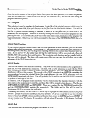
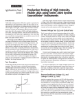
The %M memory map of the 90-30 system is shown in Figure 7. Shift register bits are allocated 16 bits
at a time, working down from the 5 12 limit of this memory type. Series One references between 340 377 (retentive coils) are mapped up from %MOOl to %MO32.
A
a43762
%M512
SHIFT REGlSTER
BITS ALLOCATED
VARIABLE DEPENDING
AS REQUIRED
ON SHIFT REGISTER
USAGE
NOT USED
%M032
SERIES ONE ADDRESSES
BETWEEN OCTAL 340 AND 377
%MOOl
Figure 7. %M Memory Usage by the Translator
11
Series One to Series 90-30 Translator
GFK-0486
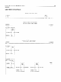
6.1.2. %T Memory
The %T memory map of the 90-30 system is shown in Figure 8. Series One references 160 through 337
(non retentive coils) are mapped up from %TOOl through %T112. Series One references from 000 to
159 which are used as internals are mapped down beginning at %T240 in the order in which they are
encountered in the original program. The translator uses %T memory above 241 for math flags. See
usage explanation under section titled Math Functions.
a43763
ST*56
n
MATH FLAGS
OAT247
NOT USED
OAT240
SERIES ONE ADDRESSES
I
000 TO 157 USED AS INTERNALS
“/oil 12
SERIES ONE ADDRESSES
BETWEEN OCTAL1 60 AND 337
“/oTOOl
Figure 8. %T Memory Usage by the Translator
12
Series One to Series 90-30 Translator
GFK-0486
6.1.3. %R Memory
Registers are allocated by the program beginning with %ROOOl and working up, in the order in which
registers are encountered in the original Series One program. Registers 301 and 302 are reserved as the
equivalent of the Series One ACCUMULATOR;
303 and 304 are the equivalent of the AUX ACCUGULATOR.
Registers between 3 19 and 5 12 are used for TIMER ANti COUNTER functions which
require 3 registers each.
%R512
a43764
TIMER AND COUNTER REGISTERS
OAR319
NOT USED
OAR304
ACCUMULATORS
%R301
SERIES ONE REGISTERS
%ROOl
Figure 9. %R Memory Usage by the Translator
6.2. Algorithms
Used
To the maximum extent possible, the translator attempts to emulate the operation of the Series One PLC.
In the case of contacts and coils, the translation is straight forward. Other elements warrant some
explanation.
6.2.1. Timers and Counters
Series 90-30 timers and counters do NOT have a coil associated with the element, but since the Series
One does, each occurrence of a timer or counter is brought out to an internal coil. Use of contacts from
the original Series One timer or counter will use the internal 90-30 coil.
6.2.2. Sequencers
Counters in the Series One PLC are frequently used together with the STEP function to effect a
sequencer. The translator will implement the counter in the normal way. The STEP function will be
replaced with a separate rung which includes a compare function brought out to an internal coil.
Contacts from the internal coil will replace the STEP references throughout the program.
6.2.3. Shift Register
This is one of the more difficult program elements to translate from Series One to Series 90-30. Series
One shift registers can start with any bit in the 400 - 477 series; can manipulate a group of any length;
and operates directly on the bits in question. Series 90-30 must start with a bit on a word boundary;
must manipulate words, ie. 16 bits or multiple thereof; does NOT operate directly on the bits in question,
but takes word(s) as input, performs the shift on an internal image, ie. leaving the input unchanged, and
Series One to Series 90-30 Translator
13
GFK-0486
places the result at the specified output reference.
an example will aid in understanding.
The translator will handle all these complexities,
but
If a Series One shift register of 7 bits, using a START bit 400 and a STOP bit 406 were translated, the
logic goes as follows:
1 . Allocate
16 bits (since less than 16 are used) from the top of %M memory,
2 . Select a SHL - WORD instruction
ie. bits 497 - 512.
since the Series One bits are in natural order, ie. not reversed.
3 . Right justify by mapping bits in order
Series
400
401
402
403
404
405
406
One
=
=
=
=
=
=
=
Series 90-30
497
498
499
500
501
502
503
Bits 504 through 512 in the 90-30 will be wasted or unused in this case.
< -----SHIFT LEFT
*******************************************************************
*512
*503 * 502 *501 *500 *499 *498
unused
*******************************************************************
*497*
If the Series One bits had been reversed, ie. START 406 and STOP 400, step 1 above remains the same ;
a SHR_WORD instruction would have been selected in step 2 ; bits would be left justified in step 3
according to the following:
406
405
404
403
402
401
400
=
=
=
=
=
=
=
512
511
510
509
508
507
506
Bits 497 through 505 in the 90-30 will be wasted or unused in this case.
SHIFT RIGHT
---->
********~**********************************************************
unused
*512 *511 jr510 *509 *508 *507 *506 *
*******************************************************************
In both cases, the IN and OUT for the selected 90-30 function will be specified
497*
as %M497.
6.2.4. Math Functions
Series 90-30 registers 301 and 302 are designated to act as ,the Series One accumulator; registers 303
and 304 act as the aux accumulator. All math functions will act on these registers. Bits are assigned as
equivalents to the Series One Plus flags according to the following table:
14
Series One to Series 90-30 Translator
GFK-0486
Special Math Function Coil
I %T248
I M-START
1 - EACH MATH RUNG USES THIS -1
Series One Equivalent Math Flags
90930
REFERENCE
FLAG
INDICATION
SERIES ONE
REFERENCE
%T242
%T243
%T244
%T245
%T246
%T247
GREATER THAN
EQUAL
LESS THAN
CARRY
ZERO
OVERFLO
772
773
774
775
776
777
Since the Series One Plus BCD math accumulator was limited to 4 BCD digits, the register equivalent in
the 90-30 is corrected if 9999 is exceeded, and the OVERFLOW flag is set.
The Series One Plus compare function is replaced by three separate compares which set the appropriate
flags above.
6.3. Programmer Intervention
Due to the substantial differences in the math functions between the two PLC’s, manual intervention
will probably be required in this area. Flag usage is shown in the following table:
Untranslated
Function Flags
%T256
%T255
%T254
%T253
%T252
XLATERR
MATH FUN
DECODE
ENCODE
BCD_BIN
%T25 1
BIN_BCD
%T250
D-OUT
%T249
D-STORE
-
INDICATES
INDICATES
INDICATES
INDICATES
INDICATES
FUNCTION
- INDICATES
FUNCTION
- INDICATES
FUNCTION
- INDICATES
FUNCTION
A
A
A
A
A
TRANSLATION
ERROR
MATH FUNCTION
DECODE FUNCTION
ENCODE FUNCTION
BCD TO BINARY
A BINARY
TO BCD
A SERIES ONE D-OUT
A SERIES ONE D_STR
Using the SEARCH capability of Logicmaster 90-30, each of the above flags must be located and
appropriate logic substituted to duplicate the necessary function from the corresponding
area of the
Series One program.
XLATERR probably indicates use of a FUN20
you are NOT translating the math functions.
or High Speed Counter.
MATH - FUN only appears if
Series One to Series 90-30 Translator
15
GFK-0486
The translator treats all moves into and out of the accumulator as l&bit moves, but then flags the
instruction by adding a coil with nickname D STR or D OUT. If your program used any of the 4 or 8
bit Series One instructions, you must perform the masking and shifting operations.
The translator performs no conversions, ie. BCDBIN
and BIN_BCD instructions are merely flagged.
Realizing that all math in the Series 90-30 is performed in binary (as opposed to the Series One Plus
BCD math), you must add the appropriate data conversion instructions for your application.
Likewise, the ENCODE and DECODE instructions from the Series One Plus are merely flagged.
program user must determine the appropriate action to take at these points in the program.
The
As an aid to your further understanding, Series One Plus math functions and their corresponding 90-30
implementations as performed by the translator are included in the Appendix. You will note that one of
two approaches is used depending on flag usage in your Series One program. When flags are used, the
algorithm emulates all of the flags associated with that function in the Series One Plus.
16
Series One to Series 90-30 Translator
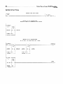
GFK-0486
SUBTRACT FUNCTION
SERIES
ONE PLUS
RUNG
INPUT1
001
+ --
1 c----------------------------------------------------------
WITH
+[
K 0005
SUB
FUN
72 ]
SERIES go-30 EQUIVALENT
NO CARRY OR ZERO FLAG USAGE
IINPUT1
+ -- 1 c--------------------------------------------------------------------IM - START +-----+
+
SUB +1 [ ---+
M - START
( 1 --
-0
1 ACCUM
/ CONST
+00005
-+I1
Q+- ACCUM
-112
/
+-----+
SERIES go-30 EQUIVALENT
WITH CARRY OR ZERO FLAG USAGE
IINPUT1
+ -- 1 c---------------------------------------------------------------------
M - START +-----+
-- 1 E---+
SUB +--------
+
-----0-+
M - START
( ) --
11-m-0
+
LT
1 INF
ACCUM
-+I1
Q+- ACCUM
1 -k /
CONST
+00005
+-----+
ACCUM
-+I1
Q+---------
ADD
+--0----0-0-0-0---0-(
)--
INTCONST
-+I2
ACCUM
11
+ooooo+----4
CONST -+I2
1
+10000 +-----+
IM- START
+-----+
ACCUM
-+I1
CONST
-+I2
'
Q+ -----------------------------------------------------------
I
ZERO
( 1 --
17
Series One to Series 90-30 Translator
GFK-0486
ADD FUNCTION
SERIES
ONE PLUS
INPUT - 1
+ -- 1 I:-~LIIIll~~~~~~~l~~~~-~~~~~~~~~---
WITH
[ ~~~1-~111-~~~~~1~~~~~~~~~~
<< RUNG
M - START
+
1 L:---+
I_
ACCUM
6
STEP
#0005
~111~~~1~~~1~~1~~-~~~~~~~~
+ [ADD
FUN
711
SERIES go-30 EQUIVALENT
NO CARRY OR ZERO FLAG USAGE
INPUT1
+--I
RUNG
--~~-111-~~-~~~111~~~~~~~-~~~~~~~~~~~~~~~~-
M - START
( 1 II
>>
+-----+
ADD -I+INT
I
I
-+I1
Q+- ACCUM
’ I
CONST -+I2
+00009 +-----+
SERIES go-30 EQUIVALENT
WITH CARRY OR ZERO FLAG USAGE
M - START
INPUT1
+
TART +
-----------------+
GT
w-11
ADD
+
+
[
INT-1
I IN?
-1-11
----II
+
+
ACCUM
I
-+I1
I
Q+- ACCUM
CONST -+I2
'
I
+00009 +------+
I
ACCUM
-+I1
I ---------+ +
--L-I
Q-t
CONST -+I2
+09999+-----+
ACCUM
+
SUB +~-~~-~~~~-~--~~~~~~(
INT-
I
-+I1
CARRY
)--
I
Q+- ACCUM
CONST -+I2
+10000 +-----+
M-START
+
LI
+-----+
1 [:---+ 1 EQ_
I
INT
ACCUM
-+I1
CONST
-+I2
I
1
I
Q+ ~II~~LIIII~~~~~~~~~~~~~~~~~~~~~~~~~~~~~~~~-~-~~-~~~~~~~~~~~
’ I
+ooooo+-----+
ZERO
( 1 -II
18
Series One to Series 90-30 Translator
GFK-0486
DIVIDE FUNCTION
SERIES
ONE PLUS
RUNG
/INPUTS
K 0004
[ DIV
FUN
WITH
SERIES go-30 EQUIVALENT
NO ZERO OR OVERFLOW FLAG
WITH
SERIES go-30 EQUIVALENT
ZERO OR OVERFLOW FLAG USAGE
74 ]
USAGE
M START +-----+
-+--I
[---+ DIV -.+I
INT
ACCUM
I
-+I1
I
Q+- ACCUM
CONST -+I2
1
+00004 +-----+
M - START
ACCUM
+ ----- +
+-----+
I
INT
-+I1
I
Q+-AUXACC
I
I
CONST -+I2
)
+00004 +-----+
M - START
ACCUM
I
INT
-+I1
OVERFLO
I
Q+- ACCUM
’ I
CONST -+I2
+00004 +-----+
+-----+ I
I
INT
ACCUM
-+I1
CONST
-+I2
'
I
Q+ -----------------------------------------------------------
+ooooo+-----+
I
ZERO
( 1 --
Series One to Series 90-30 Translator
19
GFK-0486
MULTIPLY FUNCTION
SERIES
+ --
ONE PLUS
RUNG
INPUT1
001
REGl
R 651
+[ MPY
1 [ ~~~-~~~~~~~11~~1111~~~~~~~~~~-----------------~~--~~~~~~~-
FUN
73 ]
SERIES go-30 EQUIVALENT
WITH NO ZERO FLAG USAGE
IINPUT1
+ -- 1 [ 1~~~~~~~111~~~~~~~~~~~~~~~~~~~~~~~~---------~~---~~~~~~-~~~~~-~~-~~~~
M - START
( 1 --
IM START +-----+
-+-1
c---+ MUL -.+-
I
INT
ACCUM
-+I1
%Roool
-+I2
+
I
Q+- ACCUM
’ I
-1-W-
+
SERIES
WITH
go-30 EQUIVALENT
ZERO FLAG USAGE
IINPUT1
+ -- 1 c~~~~1-1~~~~~~1-~~~~~~~~~~~~~~~~~~~~-------~~~~~~~~~~~~-~~~~~~~~~~~~~~
IM
START
I_
+-1
[ ---+
ACCUM
%Roool
I
Q+- ACCUM
-+I2
+ -mm-- +
[ ---+
ACCUM
+-----+
NE
IN?
I
-+I1
+ -w-m- +
I
Q+---------+
DIV
+ ---I- +
+-v-w-------------+
MOD
I
-+I2
’
I
ACCUM
-+I1
+~~~~~~~~-~~--~~~~~~(/)~~
INT-
INTCONST
( ) --
+-----+
MUL +INT-
I
-+I1
M START
mm
+-1
M - START
I
Q+-AUXACC
ACCUM
I
-+I1
I
Q+- ACCUM
+ooooo+----4
CONST -+I2
+10000 +------+
CONST -+I2
+10000 +-----+
ZERO
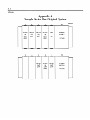
A-l
Appendix A
Sample Series One Original System
5
24 VDC
IN
8 PT
SINK
5
4
3
RELAY
OUT
8 PT
RELAY
OUT
8 PT
4
3
RELAY
OUT
8 PT
2
24 VDC
IN
8 PT
SINK
2
24VDC
IN
8 PT
SINK
PS
CPU
POWER
SUPPLY
Sl
ll5VAC
1
PS
RELAY
OUT
8 PT
POWER
SUPPLY
ll5VAC
a43765