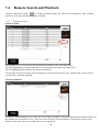
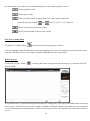
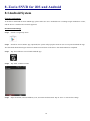
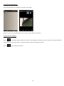
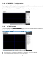
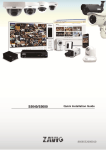
1
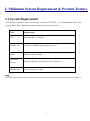
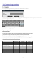
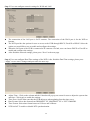
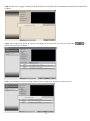
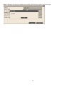
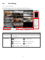
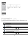
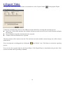
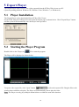
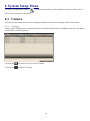
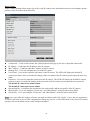
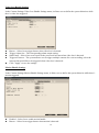
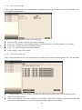
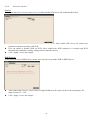
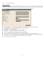
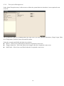
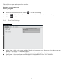
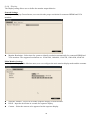
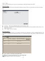
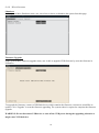
0 Content 1. Safety Instruction……...…………………………………………………………………..…………………..3 2. Minimum System Requirement & Product Feature…………………...……………………………………5 2.1 Minimum System Requirement…………………………………………………………………………….5 2.2 Product Feature…………………………………………………….……………………………………….6 3. General Operation………...…………………………………………………………………………………….8 3.1 Login…………………………………………………………………………………………………………8 3.2 Add IP Cameras to NVR………………………………………………………………………………......9 3.2.1 Wizard-Full Auto Install Mode (Plug and Play)…………………………………………………………9 3.2.2 Wizard-Manual Install Mode…………………………………………………………………………10 3.2.3 Manual Install……………………………………………………………………………………...13 3.3 Live Viewing…………………………………………………………………………………………15 3.3.1 Basic Operation…………………………………………….…………………………………………15 3.4 Search and Playback Operation………………………………………………………............................16 3.4.1 Basic Operation……………………………………………………………………………………….16 3.4.2 Calendar………………………………………………………………………………………………17 3.4.3 Search Operation………………………………………………………………………………………18 3.4.4 Playback Operation……………………………………………………………………………………19 3.5 IP Device Discovery………………………………………………………………………………………20 4. Export Video…..………………………………………………………………………………….……………21 5. Export Player..…..……………………………………………………………………….………………….…22 5.1 Player Installation ….……………………………………………………………….……………………..22 5.2 Starting the Player Program……….……………………………………………….………………..….…22 6. System Setup Menu……………………………………………………………….……………………….….24 6.1 Camera…….……………………………………………………………………….………………..….….24 6.1.1 Settings…….……………………………………………………………….………………..…………..24 6.1.2 Record Settings…….……...……………………………………………….…………….…...……….…29 6.1.3 Schedule Settings…..……………………………………………………….…………….…..…….…...29 6.2 Network………….………………………………………………………….……………………….…….30 6.2.1 Network Settings…………...…………………………………………………………………………30 6.2.2 Network Service……………..…………………………………………………………………………32 6.2.3 Network Notification…………………………………………………………………………………33 6.3 Alarm Settings……………………………………………………………………………………………..34 6.3.1 Alarm Input Settings……………..……………………………………………………………………34 6.3.2 Exception Management…………………………………………………………………………………35 6.4 System Settings..…………………………………………………………………………………………36 6.4.1 Device Setting…………………...……………………………………………………………………36 6.4.2 User Settings…………………….………………………………………………………………………36 6.4.3 Date/Time Settings……………………………………………………………………………………37 6.4.4 Display……………………….…………………………………………………………………………39 1 6.4.5 Disk……………………………….……………………………………………………………………40 6.4.6 Miscellaneous……………………………………………………………………………………………41 6.4.7 Configuration…………………….……………………………………………………………………42 6.5 Information……………………………………………………………………………………………..43 6.5.1 General Information…………………………………………………………………………………43 6.5.2 Log………………………………………………………………………………………………………43 7. Web Viewer Operation…………………….………………………………………….………………….44 7.1 Connecting to NVR..………………………………………………………………………………….…..44 7.2 Login………………………………………………………………………………………….……44 7.3 Remote Live View……………………………………………………………………………….…………46 7.4 Remote Search and Playback…………………………………………………………………….……….48 7.4.1 Remote Search…………………………………………………………………………………………48 7.4.2 Web Viewer Playback Operation………………………………………………………………………49 8. Zavio SNVR for iOS and Android….……………..……………………………………………….…………52 8.1 Android System……..……………………..………………………………………………………………52 8.2 iOS System………………………………………………………………………………………………….54 9. CMS Pro Operation…...………………………………………………………………………………………56 9.1 Begin Installation…………………………………………………………………………..…….…………56 9.2 Start CMS Pro from the PC…………………………………….……………………………….…………..59 9.3 CMS Pro UI Overview…………...…………………………………………………………………………59 9.4 Login……………………………………………………………………………………………………......60 9.5 Connect the program with device……………………………………………………………………….......60 9.5.1 Add Device Manually……………………………………………………………………………………..60 9.5.2 Remove or Edit device setting…………………………………………………………………………….61 9.5.3 CMS Pro Group Video……………………………………………………………………………………61 9.6 Live Video…………………………………………………………………………………….…...……...63 9.7 Playback Video………………………………………………………………………………………...……64 9.7.1 Search for Playback Videos………………………………………………………………….……………65 9.7.2 Search Operation………………………………………………………………………………..………65 9.8 CMS Playback Operation……………………………………………………………………………...……67 9.9 CMS Export…………………………………………………………………………………………………67 9.10 CMS PTZ Configuration…………………………………………………………………………………..69 9.11 CMS System………….…………..…………………………………………………………………...…...69 Appendix: Compatible hard disk list………………………………………………………………………….71 2 User Manual 1. Safety Instruction Before you use this product This product has been designed with safety in mind. However, the electrical products can cause fires which may lead to serious body injury if it is not used properly. To avoid such accidents, be sure to heed the following. Legal Caution Video and audio surveillance can be forbidden by laws that vary from country to country. Check the laws in your local region before using this product for surveillance purposes. Don't use the accessories not recommend by the manufacturer Heed the safety precautions Be sure to follow the general safety precautions and the “Operation Notice.” Operation Notice - Operating or storage location Avoid operating or storing the camera in the following locations: Extremely hot or cold places (Operating temperature: 0 °C to + 50 °C [14 °F to 122°F] ) Exposed to direct sunlight for a long time, or close to heating equipment (e.g., near heaters) Close to water (e.g.,near a bathtub, kitchen sink, laundry tub) Close to sources of strong magnetism Close to sources of powerful electromagnetic radiation, such as radios or TV transmitters Locations subject to strong vibration or shock In case of a breakdown In case of system breakdown, discontinue use and contact your authorized dealer. In case of abnormal operation If the unit emits smoke or an unusual smell. 3 If water or other foreign objects enter the cabinet. If you drop the unit or damage the cabinet:1 Disconnect the cable and the connecting cables. 2 Contact your authorized dealer or the store where you purchased the product. Transportation When transporting the SNVR, repack it as originally packed at the factory or in materials of equal quality. Ventilation To prevent heat buildup, do not block air circulation around the device. Cleaning Use a soft, dry cloth to clean the external surfaces of the device. Stubborn stains can be removed using a soft cloth dampened with a small quantity of detergent solution, then wipe dry. Do not use volatile solvents such as alcohol, benzene or thinners as they may damage the surface. 4 2. Minimum System Requirement & Product Feature 2.1 System Requirement For normal operation and remote web viewing of SNVR, it’s recommended that your system meet these minimum requirements for proper operation: Item Requirements CPU Minimum Intel i3 or higher Graphic Card Minimum 128MB independent graphic card RAM Minimum 4GB of RAM Operating System Microsoft Windows XP, Windows Vista, Windows 7 Web Browser Internet Explorer 8 or later Note: The above system requirements is only for web viewing. The system requirements for CMS , please refer to chapter 9. 5 2.2 Product Features System 4 Channel 8 Channel Operating System Embedded Linux Operations Live, Recording, Playback, Backup & Remote access Control Mode Video USB mouse, Webpage, CMS Decompression H.264 HP/MP/BP, up to 1080p30 IP Camera Inputs 4 channel; each one is up to 1080p30 8 channel; each one is up to 1080p30 Audio Input 1 x RCA Output 1 x RCA Audio Recording Display Yes Display mode Full screen/Multi-screen/PIP/Sequence Output Output: 1 x HDMI (1920x1080,60Hz), 1 x VGA (up to 1920x1080,60Hz) Sequence Yes OSD GUI Remote View Yes, Via IE Web Viewer, CMS Mobile Viewing on Yes(iOS & Android) Smartphone/Tablet PC Recording Recording Mode Continuous, scheduled, alarm, motion Recording Capability Up to 120 fps at Full HD(1920x1080) Pre Recording 5 seconds Post Recording Playback & Backup 255 seconds Display mode Full screen/Multi-screen Playback capability 4 channel simultaneous playback Playback control Play/Pause/Step/Fast forward/Rewind/Fast rewind Search Control By Channel, Date/Time, Events Export Through USB/Webpage/CMS Internal Storage Network Up to 2 x SATA HDDs Support TCP/IP,SMTP,DHCP,DDNS,PPPoE,UDP,SSL,RTP,RTSP,NTP Ethernet I/O 1x10/100Mbps(WAN), 1x10/100/1000Mbps(LAN) USB 2 (1 for mouse control and 1 for backup) Alarm 4 Alarm in/ 1 Alarm out RS485 1; Support Pelco D, Pelco P 6 Up to 240 fps at Full HD(1920x1080) 8 channel simultaneous playback 8 Alarm in/ 2 Alarm out Security Watermark Yes User Privilege 3 Levels of User Access Support Environmental Power Supply Input: AC100~240V, 50 / 60 Hz Dimension Output: DC12V / 5 A 303(W) x 58.2(H) x 226(D) mm±5mm Temperature 0°C ~ 50°C [14 °F to 122°F] Working humidity 10%RH ~ 90%RH 7 3. General operation 3.1 Login It is requested to login after boot up if the user authentication is enabled. Click on the User and Password column to bring up the virtual keyboard to enter the preset user account and password to login to the system. The default user name/password is: Administrator: admin/admin Operator: operator/operator Guest: guest/guest If Auto logout is enabled, the system will automatically logout after the preset time. To login to the system, left click on the mouse to bring up the login menu. The functions available can be limited by setting passwords. Access to the unit’s functions is determined by the user level of the user logged in. Authority Instructions based on 3 levels of users View live OSD Live Multiple-up Zoom Pan/Tilt/Zoom (PTZ) Playback Export Acknowledge Alarm Configuration Administrator Yes Yes Yes Yes Yes Yes Yes Yes Yes Operator Yes Yes Yes Yes Yes Yes Yes Yes No 8 Guest Yes Yes Yes Yes No No No No No 3.2 Add IP Cameras to NVR 3.2.1 Wizard-Full Auto Install Mode (Plug and Play) When the first time connect IP cameras to the NVR, the NVR will pop up install wizard window. Please click “Full Auto Install” and enter IP cameras’ user account and password ,and then the NVR will automatically configure IP cameras connected by LAN. After few seconds, the NVR will detect the IP cameras and display image. Note: 1. User also can go to ConfigurationSystem DeviceInstall WizardGo to bring up Install Wizard. 2. The connected IP cameras must be specific IP camera models. 3. The IP camera is powered on before the NVR is power on. When the NVR does not configure the IP camera automatically, please ensure the IP camera model name and IP camera is power on before NVR. 9 3.2.2 Wizard-Manual Install Mode If user would like to add IP camera manually in wizard, please follow the below steps. Step 1. Click “Manual Install” and press “Next’ to the next page. Step 2. User can configure NVR device settings. User can change the device name, select the desired display language, enable or disable authentication or keep the recorded data in hard disk or not. After finish the device setting, please click “Next” to the next page. 10 Step 3. User can configure network settings for WAN and LAN. The connection of the LAN port is for IP cameras. The connection of the WAN port is for the NVR to Internet. The NVR provides the options for user to access to the NVR through DHCP, Fixed IP or PPPoE. Select the option user would like to use to enable and configure the settings. When the LAN port of the NVR is connected to IP cameras via a hub, user can choose DHCP or Fixed IP to enable and configure the settings. After finish the network settings, please press “Next” to the next page. Step 4. User can configure Date/Time settings of the NVR. After finish the Date/Time settings, please press “Apply” to save user’s changes and proceed to the next step. Adjust Time : Click on the column and the Calendar will pop up on screen for user to adjust the system date and time. Click Apply to enable the settings. Time Zone: Set the time zone that the NVR adjusts to when updating from the time server. Date Format: Select date format from DD/MM/YYYY, MM/DD/YYYY or YYYY/MM/DD. Time Format: Select time format between 12 Hours and 24 Hours. NTP On/Off: To enable or disable NTP synchronization. 11 Step 5. After press “Apply” button, the NVR will start to scan the LAN environment to search for the specific IP cameras. Step 6. After NVR gets the specific IP cameras, it will display the IP camera list. User can click “Add” button add IP camera into desired channel. Step 7. After adding IP cameras into NVR, NVR will start to configure the parameters of the IP cameras. 12 to Step 8. When NVR finish the configuration of the IP cameras, it will pop up the success message and IP camera also successfully add into NVR. 3.2.3 Manual Install User can add IP cameras manually in Camera-Settings menu by following the below steps. Step 1. Please click “Manual Install” button to add IP camera. Step 2. After click “Manual Install” button, NVR will pop up the below screen. Please select IP camera model name, IP address, user name, password, camera channel and stream profile. After finish the settings, please click “Apply” to save the parameters and proceed to the next step. 13 Step 3. When the IP camera is installed successfully, NVR will pop up the success message. 14 3.3 3.3.1 Live Viewing Basic Operation The NVR will enter into the Live View mode after user login to the system. Use mouse to double click on any video channel to bring it up to full screen display. D E B C A The basic operation icons are showing on the main screen, the functions are: Main screen To switch channel in the display window, move the focus channel to the A. Channel and audio selected window, click on the channel button user wish to display, the channel will be switched. B. Display mode Single view 3x3 display mode PIP display mode Sequence display mode Quad display mode Show/Hide OSD Switch display to full screen display mode 15 C. Function control Alarm acknowledge, click to disable buzzer when alarm is triggered. Click to bring up Setup menu Click to bring up Export menu Click to switch to search and playback mode Under full screen mode, click the button to enable Digital Zoom function. Right click on the mouse to drag on the screen to zoom in the selected area. D. Time and HDD It indicates the current system time and HDD information. E. PTZ panel If SNVR is connected to a PTZ device which includes RS485 PTZ device or Network PTZ device, the PTZ panel can work with the following functions: 8 way pan/tilt control: To pan/tilt the PTZ device to up/down/left/right/up right /up left /down right / down left. Speed : There are five levels of speed (Lowest/Low/Normal/High/Highest) can be applied when press the pan/tilt control. Set: To save the current PTZ position as it’s internal preset position. Go : Go to the preset position Quick Preset 1–10 : The quick button to go to the preset positions. 16 3.4 Search and Playback Operation 3.4.1 Basic operation To search and playback the video, click “Playback” button on the main page to switch to playback mode as show below. The display mode controls are the same as under Live View mode. The function controls are as below: Click to bring up the Export menu Under full screen mode, click to enable Digital Zoom function. Right click on the mouse to drag on the screen to zoom in the selected area. Click to switch to live view mode 3.4.2 Calendar The calendar on the screen shows the recorded data contains in the hard drives. The orange highlighted date indicates the recorded data in the hard drives. The red highlighted date indicates the current search date. Click on the calendar to select the date user would like to search. 17 3.4.3 Search operation The recorded file list is showing in the column below, the files can be searched by “Time”, “Channel” and “Event”. Select the search type and the results will show in the list below. Double click on the selected file then the video will start to play on the display window. Search by Time Select Time Search, all the video files of the selected date will be shown in the list. Each file contains maximum 60 minutes of the video. Select the time range user would like to view and double click the item to start to play on the display window. Search by Channel Select the channel that user would like search. All the event video files of the selected date and channel will be shown in the list. Select the event video user would like to view and double click the item to start to play on the display window. 18 Search by Event The system provides the option to search the video by each event type and channel. All the event video files of the selected event type and channel will be shown in the list. Select the event video user would like to view and double click the item to start to play on the display window. 3.4.4 Playback operation Please refer to the below for the playback control function: The progress bar shows the current playback status and timeline. Drag the time indicator on the progress bar to move to the selected timeline to playback. On the time bar, it also indicates the initial and end time of the current playback section. Icon Function instruction Click to playback video Click to pause video Click to reverse playback Click to switch to fast forward playback, use and to adjust playback Speed, in x0.25, x0.5, x1, x2, x4 and x8. Pause the video and click the button to step forward playback. Click to fast forward to the next section Click to switch to fast reverse playback, use x4 and x8. 19 and to adjust playback speed, in x1, x2, and Pause the video and click the button to step reverse playback. Click to fast backward to the previous section 3.5 IP Device Discovery Click “Configuration” button and select camera to start setting IP cameras(s) connected in the same network segment (192.168.1.x by default). After NVR finish scanning, user will see the list of every connected IP cameras with its detailed information, MAC address and connection status to the NVR. 20 4.Export Video To export the video from NVR hard disk to external device, click “Export” button to bring up the Export menu shown as below. Connect the external storage device to the USB port on the unit before executing the exporting process. Start Time: Click on the date/time, the calendar will pop up on the screen for user to select the date and input the start time. Record Duration: Input the data duration to be exported. Channel: Select the channels to be exported. The data contents will be shown in the list. The total data size and available external storage size will be shown under the list. User can assign the recording path by clicking the “ Open Folder” icon. Click Start to execute the exporting process. User can view the exported video by the Export Player. Click Export Player to download to the pen drive if the user does not have the Export Player installed. 21 5 Export Player The Export Player allows user to view video exported from the NVR or Web viewer on a PC. (System operating platform: Windows XP, Windows Vista, Windows 7, or Windows 8.) 5.1 Player Installation The Export Player can be downloaded from NVR or Web Viewer. On the NVR, insert the USB pen drive then start the Export page as shown below. Click “Export Player” button and the system will automatically store the Player in the pen drive. 5.2 Starting the Player Program Double click on the “Player.exe” file to start the program. The Player will be displayed as shown below: To open a video export file, click “Open” button to select the exported file. Drag the files to the window that would like to display. The Player will automatically start to play the video. Note: The Player can only play multiple channels that are within the same time duration. 22 The main functions are: Icon Function instruction Single view display mode Quad display mode Under full screen mode, click to enable Digital Zoom function. Right click on the mouse to drag on the screen to zoom in the selected area. Click to take a snapshot of the selected video. Click watermark icon to verify the video is authentic or not. The progress bar shows the current playback status and timeline. Drag the time indicator on the progress bar to move to the selected timeline to playback. Icon Function instruction Click to playback video Click to pause video Click to switch to fast forward playback, use and to adjust playback speed, in x0.25, x0.5, x1, x2, x4 and x8. Click to stop playback video Click to enable or disable audio playback. Drag the slide bar to adjust the volume. When audio is on, the user can move the focus window to the select the channel that would like to play. Click to convert the video file of the selected channel to AVI format. 23 6 System Setup Menu Click the “Configuration” button , the setup menu will be enable and shown as below. Please refer to below for the setup menu functions 6.1 Camera The camera setup menu allows user to configure the behaviors related to the input video of IP cameras. 6.1.1 Settings In the Camera-Settings menu, it displays the current IP camera information, including camera title, IP address and IP camera connecting status. Click on the for detailed setup of each IP camera. Click on the to delete IP camera. 24 Basic Setting In the Camera-Settings-Basic menu, user will see the IP camera basic information and user can configure stream profiles of the IP cameras from the NVR. Camera title – Click on the column, the virtual keyboard will pop-up for user to input the camera title. IP Address – It indicates the IP address of the IP camera. MAC address – It indicates the MAC address of the IP camera. Manage Port – User can configure the port of the IP camera. User Name – User need to input the user name of the IP camera. The NVR will display the default IP camera user name. Once user make the change of the user name of the IP camera, please input the new user name. Password – User need to input the password of the IP camera. The NVR will display the default IP camera password. Once user make the change of the password of the IP camera, please input the new password. The default IP camera user name: admin The default IP camera password: admin Stream Profiles – It indicates the resolution of the main profile and the sub profile of the IP camera. Main Profile – User can configure “Frame rate” and “Max Bitrate” of the IP camera from NVR. Sub Profile – User can configure “Frame rate” and “Max Bitrate” of the IP camera from NVR. Note: Once user make the changes of frame rate and max bitrate and click “Apply” to save the new parameters, IP camera will start to proceed the configuration. During the process, it will result in the video loss of IP camera and user will see the black screen on the configured channel. 25 Advanced Setting In the Camera-Settings-Advanced menu, user can configure video color settings of IP cameras from the NVR. User can adjust video brightness, contrast, saturation, sharpness, mirror and flip of the IP cameras. Press “Exit” to back the previous page. 26 Video Loss Handle Settings In the Camera-Settings-Video Loss Handle Settings menu, it allows user to define the system behaviors while there’s video loss triggered. Buzzer – Select On to trigger buzzer when video loss is detected. Trigger Alarm Out – The corresponding alarm output setting. Send Email – Select On to send e-mail to the preset mail account when video loss is detected. Triggered Camera – The system allows user to trigger multiple cameras for event recording, select the cameras that would like to be triggered when video loss is detected. Click ”Apply” to save the settings. Motion Handle Settings In the Camera-Settings-Motion Handle Settings menu, it allows user to define the system behavior while there’s motion triggered. Enabled – Select On to enable motion handle. Buzzer – Select On to trigger buzzer when motion is detected. 27 Spot on Main Monitor – Select On to spot on main monitor when motion is detected. Trigger Alarm Out – The corresponding alarm output setting. Send Email – Select On to send e-mail to the preset mail account when motion is detected. Triggered Camera – The system allows user to trigger multiple cameras for event recording, select the cameras that would like to be triggered when motion is detected. Click ”Apply” to save the settings. PTZ settings In the Camera-Settings-PTZ menu, it allows user to configure the settings if the NVR is connected to a RS485 PTZ camera or Network PTZ camera. Enabled – Select On to enable PTZ control. PTZ Type – It will display RS485 PTZ or Network PTZ. It depends on which PTZ type NVR connects. PTZ Protocol – Select the correct PTZ protocol type. Baud Rate – Select the speed used to transmit instruction or information through the RS485 port on the NVR. Data Bit - The data bit used for transferring. This can be set to 8 or 7 through RS485 connection. Parity: This selects the transmission level of the connection through RS485 connection. Choose either None, Odd, or Even . Stop Bit - This field is to set the stop bit for the RS485 connection. This can be set to 1 or 2. Address - The address must set to the same address of that RS485 PTZ camera. Click ”Apply” to save the settings. 28 6.1.2 Record Settings In the Camera-Record menu, user can define the recording behavior in the record setup menu. Each channel can be configured independently. Click on the selected channel to bring up the setup page. Record Audio – Enable or Disable the audio recording. Pre-event – Set the pre-event recoding duration. The maximum pre-recording duration is 5 seconds. Post-event – Set the post-event recording duration. Copy – To copy the setting to the other channels. Click ”Apply” to save the settings. 6.1.3 Schedule Settings In the Camera-Schedule menu, user can define the recording schedule and recording behavior for each individual channel in the below page. To setup schedule, select the channel from the left column, the recording option for the channel will be shown in the right column. Click on the day(Sun ~ Sat) user would like to set schedule, check in the column to enable the timelines and select the recording behaviors. User can configure multiple timelines for each day. 29 Click “Day Copy” to select the day user would like to copy to. Click “CH Copy” to allow user to copy the settings of the whole week from one channel to other channels. Click “Apply” to save the changes. 6.2 Network 6.2.1 Network Settings The Network function must be enabled and configured properly in order to access and configure the IP cameras and NVR. WAN In the Network-Settings-WAN menu, user is required to set up the WAN setting properly in order to access NVR via internet. The NVR provides the options for user to access to the NVR through DHCP or Fixed IP or PPPoE. Select the option user would like to use to enable and configure the settings. Click “Apply” to save the settings. 30 LAN In the Network-Settings-LAN menu, user is required to set up the LAN setting properly in order to access IP cameras via intranet. The NVR provides the options for DHCP or Fixed IP in LAN environment. Select the option user would like to use to enable and configure the settings. Click “Apply” to save the settings. DDNS In the Network-Settings-DDNS menu, user can select DDNS to configure the Dynamic DNS. The setup page is shown as below. Select On to enable DDNS. Input DDNS provider and enter the required information. Click “Apply” to save the settings. 31 6.2.2 Network Service Service In the Network-Service-Service menu, user can enable/disable NTP Server and enable/disable UPnP. User can enable NTP Server to make NVR as NTP Server. After enable NTP Server, IP camera can synchronize the date and time with NVR. User can enable or disable UPnP on NVR. After enabled, the NVR connects to a network and NVR automatically establishes working configurations with other devices. Click “Apply” to save the settings. DHCP Server In the Network-Service-DHCP Server menu, user can select on to make NVR as DHCP Server. After enable DHCP Server, NVR is able to assign IP address to IP camera in the LAN environment. The range is from 101 ~ 250. Click “Apply” to save the settings. 32 6.2.3 Network Notification E-Mail Notification In the Network-Notification-E-mail Notification menu, user is able to set the Email addresses and input related information. If “Send Email” is enabled in video loss, motion, alarm settings or system exception and when they are being triggered, the e-mail will be sent according to the E-mail notification setting. To Email address 1-3 – Allows user to input up to 3 email address for alarm message to send to. From Email address – Input the Email address of the sender (NVR). Email Subject – Input email subject. SMTP Server – Assign the SMTP (e-mail) server’s name. SMTP Port – Assign the port number used by the SMTP server. SSL – To enable SSL if mail server needs to be encrypted by SSL. Authentication – To enable if the SMTP server requires authentication. (user name / password). User name / Password – Input the login user name and password if the SMTP Server requires authentication. Send test mail – Click to send the test email according to the current settings. Click “Apply” to save the settings. 33 6.3 Alarm Settings 6.3.1 Alarm Input Settings In the Alarm-Settings menu, user can define the alarm behaviors and the corresponding actions for triggered alarm. Alarm input – Select the alarm input number from 1 to 8, the corresponding settings will show in the window. Enabled – Select On to enable the alarm. Alarm name – Input the name for the alarm. Alarm type – Select the alarm trigger type. N.O. – Normal open contact, N.C – Normal Close contact Trigger Duration – Select the trigger type and time duration Timeout – The alarm will last for the set time duration. Transparent – The alarm output remains active until the triggered event ends. Non-Stop – The alarm will be continuously active until user presses “ACK” key. Alarm Handle – To configure the system monitor and alert behavior when the alarm is triggered. The settings include buzzer, spot option, trigger alarm out, send Email. Triggered Camera – The system allows user to trigger multiple cameras for event recording, select the cameras that would like to be triggered when alarm is detected. Click “Apply” to save the settings. 34 6.3.2 Exception Management In the Alarm-Exception menu, it allows user to define the system behavior when there’s an exceptional event occurred. The exceptional events are including Disk full, Disk error, No disk, Network Disconnect, Illegal Login, Disk Over Temperature, Fan Fail, Power loss and IP conflict. Select the exception and define the behaviors as below: Buzzer – Select On to enable buzzer when the exceptional events occur. Trigger Alarm Out – Select the Alarm out to trigger when the exceptional events occur. Send Email – Select On to send Email when the exceptional events occur. 35 6.4 System Settings 6.4.1 Device Setting In the System-Device menu, user can configure the device related settings. Device Name – Input the name for the NVR. Device No. – Input the number for the NVR. Language – Select from the list for the language to be displayed on the local NVR. Enable Authentication – Select On to active the user login. If user select Off, no user name or password is required to access the system. Auto Scan & Add IP-Cameras –Select On to active auto scan & add IP cameras. The NVR will continually scan the IP camera and check whether there is a new IP camera in the LAN environment. When the NVR detect a new IP camera in the LAN environment, NVR will automatically add the IP camera into NVR when there is still spare channel existing in the NVR. Install Wizard – Click “Go” to bring up Install Wizard menu. Click “Apply” to save the settings. 6.4.2 User Settings User setting page is where user can add or delete users on the system. 36 The default user name and password are as below. Administrator: admin/admin Operator: operator/operator Guest: guest/guest Double click the selected user or click on Click on to delete the user. However, at least one administrator is required to operate the system. Click on to add new user. 6.4.3 to edit the user settings. Date/Time Settings General Setting Adjust Time – Click on the column and the Calendar will pop up on screen for user to adjust the system date and time. Click “Apply” to enable the settings. Time Zone – Set the time zone that the NVR adjusts to when updating from the time server. Date Format – Select date format from DD/MM/YYYY, MM/DD/YYYY or YYYY/MM/DD. Time Format – Select time format between 12 Hours and 24 Hours. 37 DST Settings (Daylight Saving Time) Enabled – Select On to enable daylight saving time. Start time – Set the start date and time of daylight saving time. End time – Set the end date and time of daylight saving time. DST Bias – This allows users to select the amount of time to move forward from the standard time for daylight saving time. Available options are 30, 45, 60, 90 and 120 minutes Click “Apply” to save the settings. NTP Client Settings Enabled – Select On to enable NTP synchronization. Sync. Interval (mins) – Input the frequency that the system automatically updates the time. Click the button “Sync. Now” if immediately synchronization is needed. NTP Server – Input the time server address for time synchronization. The default NTP server is “time.stdtime.gov.tw”. NTP Port – The default setting is “123”, user can define NTP port according to the network environment. Click “Apply” to save the settings. 38 6.4.4 Display The Display setting allows user to define the monitor output behavior. General Settings In the System-Display-General menu, user can select the proper resolution for connected HDMI and VGA monitors. Monitor Resolution –Select Auto for system to identify resolution automatically for connected HDMI and VGA monitors. The supported resolutions are: 1920x1080, 1440x900, 1366x768, 1280x1024,1024x768. Main Monitor Settings In the System-Display-Main Monitor menu, user can configure the main monitor display mode and the contents. Sequence enabled – Select On to enable sequence display on main monitor. Dwell – Input the dwell time in seconds for sequence display. Camera – Select the cameras to be appeared on the sequence display. 39 6.4.5 Disk In the System-Disk menu, user can review and manage the hard disk settings of the NVR. General Settings In the System-Disk-General, user can enable or disable overwrite. The user is also able to select the auto delete days. Overwrite – Select On to enable hard disk overwrite when it’s full. Auto delete – The hard disk will automatically erase the data after the selected number of days. Select “0” to disable the function. Click “Apply” to save the settings. Disk Management In the System-Disk-Disk menu, it is to manage and display the information of all the available hard disk. The information is including the hard disk total storage size, current temperature, usage status, available data start/end time. Click “Format” to format the selected hard disk. WARNING: Format the hard disk will erase all existing data! Note: HDD support list please refer to appendix 2. 40 6.4.6 Miscellaneous Shutdown In the System-Misc-Shutdown menu, user can select to reboot or shutdown the system from this page. Firmware Upgrade In the System-Misc-Firmware upgrade menu, user is able to upgrade NVR firmware by store the firmware in USB drive. To upgrade the firmware, connect a USB flash device which contains the firmware version user would like to update. Click “Upgrade” to start the firmware upgrading. The system reboot is required to complete the firmware upgrade. WARNING: Do not disconnect USB device or turn off the NVR power during the upgrading otherwise it might cause NVR defective. 41 6.4.7 Configuration Restore Factory Default– User can load factory default by clicking “Default” button. Select the items that would like to be excluded from back to the factory default, the selected items will remain as the current values User Configuration – Select the configuration name and click “Save” to save the current configuration settings. Or user can select the configuration from the list and click “Restore” to restore the selected settings. Import Configuration – Click “Load from USB” button to upload NVR configuration settings from a USB flash device. Export Configuration – Click “Save to USB” to save the current NVR configuration settings to a USB flash device. 42 6.5 Information 6.5.1 General Information In the Information-Information menu, it displays the general system information. The information includes model name, firmware version, serial number, WAN IP address, WAN MAC Address, LAN IP address and LAN MAC address. 6.5.2 Log In the Information-Log menu, it allows user to filter and review the system event log. Click the date column and the calendar will pop up for user to select the day to be displayed. Click the items user would like to review and to show in the event log. The filtered log will be displayed in the page. Click “Save to USB” with a USB flash device connected to the unit, the filtered log will be saved to the USB device. 43 7. Web Viewer Operation 7.1 Connecting to NVR Users can remote access the NVR through Microsoft Internet Explorer to view live/recorded video and manage the NVR. Before accessing the web viewer, make sure that the PC and NVR are both connected to the internet and the network feature is enabled. For NVR network setup, please refer to Configuration Network Settings. System Requirement The following are minimum system requirements for web viewer. Operating System: Microsoft Windows XP, Windows Vista, Windows 7, Windows 8 Support Internet Explorer 8 and above (32 bit) CPU : Minimum Intel i3 or higher RAM: Minimum 4GB of RAM Independent Graphic Card: Minimum 128MB 7.2 Login Open IE browser and input NVR IP address in the address bar. When accessing this feature for the first time, user will be prompted by the browser to install Active X. The browser will pop up the below dialog for installation, click “Yes” to accept and start the installation. 44 After installing the Active X, the login page will be displayed for users to enter the User name and Password. Users can also select the OSD language, date format and time format from the login page. Click “Login” to enter the web viewer. The user name/password are the same as the NVR login, the defaults are: Administrator: admin/admin Operator: operator/operator Guest: guest/guest 45 7.3 Remote Live View After login to the system, the web viewer will automatically display a 4-screen live video. Double click on a video display window and it will display full screen in the selected channel. The system indicators on the screen show the system status, channel status and for user to control the audio display channel. Please refer 3.2.1 Basic Settings. The basic operation icons are showing on the main screen, the functions are: Icon Function instruction Click to switch to search and playback mode Click to switch to configuration menu Click to switch to Export mode Click to Logout from the current user’s privilege Full screen display mode Quad display mode 3x3 display mode Show/Hide OSD Talk to Server In full screen, click to zoom in/out of the selected video in 2x, 4x and 8x. Click to take a snapshot of the selected video Fixed Aspect Ratio 46 Note: For remote snapshot, please disable the protected mode in the IE browser as below 2 steps to ensure the remote snapshot perform normally. Step 1. Please click IE browser “Tools-Internet Options”. Step 2. Please un-click “Enable Protected Mode” to disable protected mode. Then snapshot will perform normally in un-protected mode. 47 7.4 Remote Search and Playback Click the “Playback” button to switch to playback mode. The video can be searched by Time, Channel and Event, select the search type to start searching. 7.4.1 Remote Search Search by Time The calendar on the screen shows the recorded data contains in the NVR hard drives. The date highlighted in orange means there’s recorded data of the date in the hard drives. The red highlighted date indicates the current search date. The recorded section list of the current selected day will be shown on the screen. Double click on the selected recorded file to start the playback. Search by Channel Search by Channel allows user to search the event video by channel. Select the date from the calendar, and select the channel user would like to view. The event video list of the selected channel will be shown on the screen. Double click on the selected recorded file to start the playback. 48 Search by Event Search by event allows user to search the event video list by channel and by event type. Select the channel user would like to view (user can also click All On or All off to enable or disable all channels), then select the event type (Alarm, Motion and Video Loss), the event video list of the selected channel and event type will be shown on the screen. Double click on the selected recorded file to start the playback. 7.4.2 Web Viewer Playback Operation Click on the “Playback” button to switch to the below menu. The progress bar shows the current playback status and timeline. Drag the time indicator on the progress bar to move to the selected timeline to playback. 49 On the time bar, it also indicates the initial and end time of the current playback section. Click to playback video Click to pause video Click to switch to fast forward playback (2x), user can also control the playback speed by clicking and , in x0.25, x0.5, x1, x2, x4 and x8. Click to fast forward to the next section Click to fast backward to the previous section Web Viewer Setup Menu Click on the “Config” button to switch to the setup menu page as below. User can configure all the NVR settings remotely through the web viewer. The setup menu operation is the same as in the NVR. Please refer to the Chapter 6 System Setup Menu for the setup details. Remote Export Click on the “Export” button from the NVR. to bring up the remote export menu, this allows user to export the video file To export the video, select the date from the calendar, the starting time of the video and channels that user would like to export. (Click All On or All off to enable or disable all channels.) Input the duration time user would like to export, the maximum search duration is 60min. Click Search to start, the searched video files will be listed on screen. 50 The maximum video file size is 2000MB, the system will automatically create new file if the searched result is over 2000MB. Double click on the selected item and the system will pop up message as below, select the location user would like to store then click Save to execute the downloading. User can view the exported file on the Export Player. If the user does not have the Player installed in the PC, click Export Player button to download the player to the PC. Please refer to Chapter 5 for Export Player operation. Remote Snapshot Click the “Snapshot” button in live mode or playback mode to store the current image as a still image and save in the PC folder. Remote Digital Zoom The function allows user to enlarge the live video at 2x, 4x and 8x in live mode or in playback mode. Move the focus to the selected video. Click “Full Screen” the selected area which user would like to enlarge. button first and then click “Digital Zoom” 51 icon and 8. Zavio SNVR for iOS and Android 8.1Android System System requirement To be able to install and run Zavio SNVR App, please make sure user’s Android device is running Google Android 2.2 or later, and the device is with wireless network supported. Download Android App Step1. Launch “Google Play Store” Step2. Search for “Zavio SNVR” App, tap Install, the system will pop-up the menu for user to Accept & download the App. The download should then begin. The Zavio SNVR icon will show on the device after the download is completed. Step3. Tap “Zavio SNVR” icon to launch Android App. Step4. Tap “Add” to add new NVR. Step5. Input NVR name, Host (IP Address), Port, User name and Password. Tap on “Save” to activate the settings. 52 To operate the Android App Tap on the NVR that user would like to open the view window. Rotate the screen, the orientation of the screen rotates with the tablet as user turn it. To select the view channel Tap on to switch the display mode between full screen and quad screendisplay. Select the display mode, and indicate the channel by tap on the number that user would like display in the selected display window. Tap on again to hide the selections. 53 PTZ Control Tap on in full screen to enable PTZ control. 8 way pan/tilt/zoom control: To pan/tilt the PTZ device to up/down/left/right/up right /up left /down right / down left. : Tap to Zoom in or Zoom out : To adjust focus to near or far : To adjust Iris to open or close : Tap to go to Home position. Preset: Tap on to bring up the preset menu for operations. Others To enable/disable audio display Under full screen mode, tap on the icon to enable the digital zoom function. To operate, place two fingers at once on the display window and pinch them together to zoom out, or spreading them apart to zoom in. The zoom in/out display ratio will be shown on the screen. (from 0.2X to 25X) Tap on Snapshot icon to store the current image as a still image and save in the device folder. 8.2 iOS System System requirement To be able to install and run Zavio SNVR App, please make sure user’s iOS device is running iOS 5.1 or later version, and the device is with wireless network supported. Step1. Select “App Store” 54 Step2. Search for “Zavio SNVR” App, tap on “Install APP”, the system will pop-up the request for user to enter login password to start downloading. The downloading should then begin. The icon will show on the device after the download is completed. Step3. Run “Zavio SNVR” Step4. Tap on Step5. to add new NVR. Input NVR name, Host (IP Address), Port, User name and Password. Tap on “Save” to activate the settings. To operate the iOS App Tap on the NVR that user would like to open the view window. Rotate the screen, the orientation of the screen rotates with the tablet as user turn it. To select the view channel Tap on to switch the display mode between full screen and quad screen display. Select the display mode, and indicate the channel by tap on the number that user would like display in the selected display window. Tap on again to hide the selections. PTZ Control Tap on in full screen to enable PTZ control. 8 way pan/tilt/zoom control: To pan/tilt the PTZ device to up/down/left/right/up right /up left /down right / down left. : Tap to Zoom in or Zoom out : To adjust focus to near or far : To adjust Iris to open or close : Tap to go to Home position. Preset: Tap on to bring up the preset menu for operations. 55 Others To enable/disable audio display Under full screen mode, tap on the icon to enable the digital zoom function. To operate, place two fingers at once on the display window and pinch them together to zoom out, or spreading them apart to zoom in. The zoom in/out display ratio will be shown on the screen. (from 0.2X to 25X) Tap on Snapshot icon to store the current image as a still image and save in the device folder. 9 9.1 CMS Pro Operation Begin Installation Simply double click user’s CD-ROM drive icon “Setup.exe” to launch the installer. Once the CMS Pro installer starts, it should begin to check the compatibility with the operating system user are running this installation on. System Requirement The following are minimum system requirements for CMS. Operating System: Microsoft Windows XP, Windows Vista, Windows 7 CPU : Minimum Intel i5 or higher RAM: Minimum 4GB of RAM Independent Graphic Card: Minimum 512MB The CMS Pro installer is in multi-language. User can choose the installer language. If user’s software is without .NET Framework 4.0, the CMS Pro installer will require user to install .NET Framework 4.0 to ensure CMS operation. 56 After click yes, there will pop up the installation progress bar to indicate the progress. The .NET Framework 4.0 installer will ask user to review the license terms. After user accept the license terms, please click “ Install” to proceed further. Please click “Next” to proceed further. Once .NET Framework 4.0 software install successfully, it will pop up the below complete message. Then user can begin to install CMS Pro software. 57 The CMS Pro installer will install the program in a default directory. User can either accept the default or choose the directory user would like to save the installer. And click “install” to proceed with the installation. The CMS Pro installer will show the installation process. Once the installation is complete, click “Finish” to exit the CMS Pro installer. 58 9.2 Start CMS from the PC The program automatically creates a shortcut icon on user’s PC after Zavio_CMS install successfully. Simply double click the icon 9.3 to launch the program. CMS UI Overview (A) Menu Bar: This is where user can access all functions of the software. (B) Device List: This is where user can add or delete or edit device group. (C) PTZ Control Panel: This is where user can pan, tilt, zoom the selected PTZ cameras. (D) System Information: It provides the information of CMS version. User can change the date format, time format and login authentication per user’s requirements. (E) Playback: Once user press the playback, it will launch playback control UI to have the further operations. 59 9.4 Login After installing the below digital signature, the login page will be displayed for users to enter the User name and Password. Click “OK” to enter CMS Pro Software. The default user name/password for CMS Pro is: Administrator: admin/admin Note: Since CMS Pro software manages multiple devices, only the administrator is authorized to use this software. The program provides multi-language support. To change the display language, please select the desired language from the CMS language drop-down menu. 9.5 Connect the program with device The main purpose of the CMS Pro software is to manage multiple devices. User would need to tell the program which device user need to manage. Users do that by adding one or more devices through the device list. 9.5.1 Add Device Manually Click the mouse right button on the “Device List” icon and “Add Device” will pop up in the same page to add it manually. It is required for the information shown below before successfully adding the device to the program. Please input device IP address, HTTP Port, User Name and Password. CMS Pro only supports RTSP Port at 554. Please note user need to use the CMS Pro administrator’s user name and password of the selected device. Without administrator privilege, user is unable to add the selected device. The default user name/password for CMS Pro is: Administrator: admin/admin 60 9.5.2 Remove or Edit device setting Simply click on the mouse right button on the selected device from the list and choose the corresponding buttons to edit device name, edit device setting or delete the device. Edit Device Name – User can edit the device name by simply click on the mouse right button on the selected device to “Edit Device Name”. After input the new device name, click”Edit” and the new device name will be updated to the device list. Device Setting – Once the IP address, user name or password of the selected device has been changed, user can input the new information by clicking on the mouse right button on the selected device. Delete Device – User can remove the device from the device list by clicking on the mouse right button on the selected device. 9.5.3 CMS Pro Group Video User can create the group to contain different videos from different devices. Click the mouse right button on the “Group” and it will pop up “Add Group”. 61 Press “Add Group” and the default “Group 1” will be generated. The group number is increased by numerical order. Click the mouse right button on “Group 1” and the below drop-down menu will be displayed. Edit Group Content Before edit group content, user need to stop stream first. Then user can drag and drop either devices or channels from the device list to the desired video windows. Open Group Stream After finish the edit group content, click “Open Group Stream” on the desired group to play the video streaming. Edit Group Name User can modify the group name. Delete Group User can remove the group from the group list by clicking on the mouse right button on the selected group. 62 9.6 Live video This page basically provides user the ability to view, and manage the video streams of each channel. The basic operations are showing on the main screen, the functions are: Icon Function instruction Icon Function instruction Full screen display mode Fixed aspect ratio Quad display mode Click to turn on/off live audio 9-up screen display mode Show/Hide OSD 16-up screen display mode Talk to Server Click to take a snapshot of selected live video Click to digital zoom the selected live video 25-up screen display mode 36-up screen display mode Click to Logout from the current page Click to stop or play the live video Take a snapshot: The function allows user to take the snapshots of the live video and save them on user’s local computer. Move the focus to the selected video and click “Snapshot” icon. User can save the file to a desired directory. Digital Zoom: The function allows user to enlarge the live video at 2x, 4x and 8x. Move the focus to the selected video. Click “Full Screen” icon. Then click “Digital Zoom” icon and the selected area which user would like to enlarge. 63 9.7 Playback video The program supports 1 device synchronous playback in full screen or multi-screen view. To start looking for playback videos, click “Playback” button first. The menu bar is available for each video window. The menu bar provides the following functions: The basic operations are showing on the main screen, the functions are: Icon Function instruction Icon Function instruction Full screen display mode Fixed aspect ratio Quad display mode Click to turn on/off live audio 9-up screen display mode Show/Hide OSD 16-up screen display mode Talk to Server Click to take a snapshot of selected live video Click to digital zoom the selected live video 25-up screen display mode 36-up screen display mode Click to Logout from the current page Click to stop or play the live video 64 9.7.1 Search for Playback videos Simply select a device from the drop-down device list and double click the selected device. It will pop up the calendar. 9.7.2 Search operation The recorded file can be searched by “Time”, “Channel” and “Event”. Select the search type first, choose a date, and click “Search” button. The results will show in the list. Double click on the selected file then the video will start to play on the display window. Search by Time The recorded section list of the current selected day will be shown on the screen. Double click on the selected recorded file to start the playback. 65 Search by Channel Search by Channel allows user to search the event video by channel. Select the date from the calendar, and select the channel user would like to view. The event video list of the selected channel will be shown on the screen. Double click on the selected recorded file to start the playback. Search by Event Search by event allows user to search the event video list by channel and by event type. Select the channel user would like to view (user can also click All On or All off to enable or disable all channels), then select the event type (Alarm, Motion and Video Loss), the event video list of the selected channel and event type will be shown on the screen. Double click on the selected recorded file to start the playback. 66 9.8 CMS Playback operation The basic playback operations are as below. The progress bar shows the current playback status and timeline. Drag the time indicator on the progress bar to move to the selected timeline to playback. On the time bar, it also indicates the initial and end time of the current playback section. Click to playback video Click to pause video Click to switch to fast forward playback (2x), user can also control the playback speed by clicking and , in x0.25, x0.5, x1, x2, x4 and x8. Click to fast forward to the next section Click to fast backward to the previous section 9.9 CMS Export Click on the “Export” button video file from the device to bring up the export menu, this allows user to export the 67 To export the video, select the date from the calendar, the starting time of the video and channels that user would like to export. (Click All On or All off to enable or disable all channels.) Input the duration time user would like to export, the maximum search duration is 60min. Click Search to start, the searched video files will be listed on screen. The maximum video file size is 2000MB, the system will automatically create new file if the searched result is over 2000MB. Double click on the selected item and the system will pop up message as below, select the location user would like to store then click Save to execute the downloading. User can view the exported file on the Export Player. If the user does not have the Player installed in the PC, click Export Player button to download the player to the PC. Please refer to Chapter 5 for Export Player operation. 68 9.10 CMS PTZ Configuration User can synchronize PTZ settings from all cameras connected to the NVR on the network or user can create and add new PTZ preset points to those cameras through CMS Pro. The basic operation is the same as the NVR PTZ control. Please refer to Chapter 3 for detail operation. 9.11 CMS System Click on the “System” button to bring up the system menu, this allows user to change the Date Format, Time Format, Login Authentication and CMS Version. Date Format: Select date format from DD/MM/YYYY, MM/DD/YYYY or YYYY/MM/DD. Time Format: Select time format between 12 Hours and 24 Hours. 69 Account setting: User can change CMS Pro password. Please input the old password and input the desired new password and reconfirm it. After confirmation, click “Edit”, the new password has been updated. The new password will be required when next time user login again. CMS Version: It indicates CMS Pro current version. 70 Appendix: Compatible hard disk list HDD Manufacturer Model Capacity Seagate SV35 3TB Seagate SV35 2TB Seagate SV35 1TB WD AV-GP 4TB WD AV-GP 3TB WD AV-GP 2TB WD AV-GP 1TB WD WD4000FYYZ 4TB WD WD4000F9YZ 4TB WD WD3000F9YZ 3TB WD WD2000F9YZ 2TB WD WD30EURX 3TB TOSHIBA DT01ACA300 3TB TOSHIBA DT01ACA200 2TB TOSHIBA DT01ACA100 1TB TOSHIBA DT01ACA050 500GB TOSHIBA DT01ABA300V 3TB 71