1
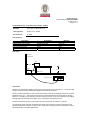
CONSUMER PRODUCTS SERVICES DIVISION
TECHNO SOURCE
Technical Report:
(5211)210-0439
Date Received:
Sample Description:
Vendor:
Manufacturer: .
Buyer:
Labeled Age Grade:
Appropriate Age Grade:
Client Specified Age
Grade:
Tested Age Grade:
UPC Code:
Test Finished Date:
August 04, 2011
Page 1 of 14
July 27, 2011
20Q ASSORTMENT SPECIALTY
1. ) RED
2. ) BLUE
3. ) PINK
N/A
On File
N/A
6+
OVER 6 YEARS OF AGE
NOT SPECIFIED
OVER 6 YEARS OF AGE
801561010961, 801561010978,
801561010985
1 AUG 2011
Sample Size:
Style No(s):
SKN/SKU No.:
PO No.:
Ref #:
Country of Origin:
36
1096, 1097, 1098
N/A
N/A
N/A
CHINA
Assortment No.:
Terminal Voltage:
(1095)
4.50 V
EXECUTIVE SUMMARY:
The sample(s) MEET the following requirement(s):
-
The tested requirements of the applicable sections of the Rules and Regulations details in 47 C.F.R., Part 15 of
the Federal Communication Commission (FCC) of United States of America and Industry Canada InterferenceCausing Equipment Standard ICES-003.
BUREAU VERITAS HONG KONG LIMITED
LYT/vh
Bureau Veritas Hong Kong Limited
Kowloon Bay Office
1/F Pacific Trade Centre, 2 Kai Hing Road,
Kowloon Bay, Kowloon, Hong Kong
Tel: (852) 2331 0888 Fax: (852) 2331 0889
www.bureauveritas.com/cps
Law Yiu Tung
Assistant Manager
Electrical Department
This report is governed by, and incorporates by reference, the Conditions of Testing as posted at the date of issuance of this report at
http://www.bureauveritas.com/cps and is intended for your exclusive use. Any copying or replication of this report to or for any other person or entity, or use of our
name or trademark, is permitted only with our prior written permission. This report sets forth our findings solely with respect to the test samples identified herein. The
results set forth in this report are not indicative or representative of the quality or characteristics of the lot from which a test sample was taken or any similar or identical
product unless specifically and expressly noted. Our report includes all of the tests requested by you and the results thereof based upon the information that you
provided to us. You have 60 days from date of issuance of this report to notify us of any material error or omission caused by our negligence; provided, however, that
such notice shall be in writing and shall specifically address the issue you wish to raise. A failure to raise such issue within the prescribed time shall constitute you
unqualified acceptance of the completeness of this report, the tests conducted and the correctness of the report contents.
TECHNO SOURCE
Technical Report: (5211)210-0439
August 04, 2011
Page 2 of 14
SUMMARY OF TEST RESULTS
The sample submitted COMPLIES with the tested requirements of the applicable sections of the Rules and
Regulations detailed in 47 C.F.R., Part 15 of the Federal Communication Commission (FCC) of United States of
America and Industry Canada Interference-Causing Equipment Standard ICES-003
Tests Required For Unintentional Radiator:
Test Executed
Test Requirement
Test Method
Limit
Status
Measurement of
Radiated Emissions
Section, 15.109
CFR47, FCC Part 15
Section 15.31,
47 CFR, FCC Part 15
ANSI C63.4-2003
See Section
15.109
CLASS B
Meet
Measurement of
Conducted Emissions on
AC Mains
Section 15.107
CFR47, FCC Part 15
Section 15.31,
47 CFR, FCC Part 15
ANSI C63.4-2003
See Section
15.107
CLASS B
N. A.
N. A. = Not Applicable
TECHNO SOURCE
Technical Report: (5211)210-0439
August 04, 2011
Page 3 of 14
Test Results:
Measurement of Radiated Emissions:
Requirements:
FCC PART 15, SECTION 15.109
Limit:
Section 15.109 Class B
Port under test:
Enclosure
Test equipment:
Description
EMI Test Receiver
Bilog Antenna
Biconical Antenna
Log-Periodic Antenna
Open Area Test Site (range = 3m)
Full Anechoic Chamber (7m x 3m x 3m)
Automatic Antenna Mast
Automatic Turntable
Antenna Mast / Turntable Controller
Coaxial Cable No. 2
Coaxial Cable No. 6
Coaxial Cable No. 3
Coaxial Cable No. 4
Loop Antenna
Brand Name
Rohde & Schwarz
Schaffner
Rohde & Schwarz
Rohde & Schwarz
None
Albatross Projects
Rainer Schäfer
Rainer Schäfer
Rainer Schäfer
Uniradio
Unknown
Suhner
Suhner
Schaffner
Model No.
ESCI
CBL6112D
HK 116
HL 223
None
M-CDC
RSM 010
RST 020
RSC
None
None
None
None
HLA 6120
Test method:
Location of test facilities:
The EMC laboratory is located at the following address:
No. 2106-2107, 21/F, Westin Centre, 26 Hung To Road, Kwun Tong, Kowloon, Hong Kong
The test facility has been found in compliance with the requirement of Section 2.948 of the FCC rules. The
information has been placed on file and listed by FCC with Registration No. 642151.
The operational mode(s) under test:
The operational modes under test are determined according to the typical use of the Equipment-Under-Test (EUT)
with respect to the expected highest level of emission. During the test, various parts of the EUT system are exercised
in a manner permitting detection of all system disturbances.
TECHNO SOURCE
Technical Report: (5211)210-0439
August 04, 2011
Page 4 of 14
The frequency range of radiated measurements:
The frequency range of radiated measurements is determined pursuant to Section 15.33.
For an unintentional radiator, unless otherwise specified, the spectrum shall be investigated from the lowest radio
frequency signal generated or used in the device, without going below 9 kHz, up to the frequency list in the following
table:
Highest frequency generated or used
in the device or on which the device
operates or tunes (MHz)
Upper frequency of measurement
range (MHz)
Below 1.705
30
1.707 – 108
1000
108 –500
2000
500 – 1000
5000
Above 1000
5th harmonic of the highest frequency or
40 GHz, which ever is lower.
Limits of radiated Emissions:
The limits of radiated emissions are specified in the appropriate Sections of the FCC rules that the EUT is subject to,
and the provisions in Section 15.35.
Unless otherwise specified in the Rules, on any frequency or frequencies below or equal to 1000 MHz, the limits are
based on measuring equipment employing a CISPR quasi-peak detector. For frequencies above 1000 MHz the
radiated limits are based upon the use of measurement instrument employing an average detector, with a minimum
resolution bandwidth of 1MHz.
When average radiated emission measurements are specified in Part 15, including emission measurements below
1000 MHz, there also is a limit on the radio frequency emissions, as measured using instrumentation with a peak
detector function, corresponding to 20 dB above the maximum permitted average limit, unless a different peak
emission limit is otherwise specified.
Measurement method of radiated emissions:
Measurements are carried out on the open area test site (OATS) located on the roof of the EMC laboratory, in
accordance with CISPR 22 as a basic standard at a measurement range of 3 meters. The test site has, by
verification measurements, satisfied the normalized site attenuation (NSA) requirements specified in the standard
CISPR 22. For measurement at each test frequency, the antenna-to-EUT azimuth is varied through 360 . The
antenna is also scanned between 1 m to 4 m in height above the ground plane to maximize the level of radiated
disturbances. The reading on the measuring receiver is observed for about 15 s for each final measurement; the
highest readings shall be recorded with the exception of any isolated spike which shall be ignored.
For measurements of undesired spurious emissions, if the measurement results are 20 dB lower than the
corresponding permissible limit levels, they can be confidently regarded as having satisfied the limit requirement
applied. No records of these measurement results are required.
For the measurements at frequencies with high ambient disturbance signals existing, verification tests may be carried
out in the Full Anechoic Chamber (FAC) as an auxiliary method to confirm whether there is any emission of radiated
disturbances from the EUT. If there is no maximum disturbance level from the EUT other than the corresponding
intrinsic noise floor of measuring system (which is at least 20 dB below the limit level), then it can be stated
confidently that the measurement result obtained at OATS is due to the signal levels of ambient signal sources, not
from the EUT.
TECHNO SOURCE
Technical Report: (5211)210-0439
August 04, 2011
Page 5 of 14
Test Set-up:
50.6
d Bu V
With hand-held or portable EUT exploratory radiated emission test shall be carried out, including rotation of the EUT
through three orthogonal axes to determine the attitude that highest emission relative to the limit. The so found
attitude and equipment arrangement shall be used in the final measurement.
In frequency range of 9kHz to 30MHz, a calibrated Loop antenna shall be applied for measuring radiated emissions.
The Loop antenna shall be positioned with its plane vertical. The centre of the loop shall be 1m above ground plane
and 3m apart from the EUT placed on the turntable. The Loop antenna shall be rotated about its vertical axis to
maximize the radiated emission measured.
TECHNO SOURCE
Technical Report: (5211)210-0439
August 04, 2011
Page 6 of 14
Results:
Operational mode under test:
On mode (with Sound, Light, Display)
EUT operating condition:
(a)
System Configuration
The EUT system is regarded as a portable apparatus and tested as a desktop device.
The EUT is configured and tested as a stand-alone unit.
(b)
Antenna (if applicable):
Not applicable
TECHNO SOURCE
Technical Report: (5211)210-0439
August 04, 2011
Page 7 of 14
Spurious Emissions of Unintentional Radiator:
Pursuant to SECTION 15.109
The measurement results are found to be more than 20dB below the permissible limit. They can then be confidently
regarded as having satisfied the limit requirement applied. No record of measurement results is therefore required.
TECHNO SOURCE
Technical Report: (5211)210-0439
August 04, 2011
Page 8 of 14
Conducted Emissions on AC mains port (150 kHz – 30 MHz)
Standard:
FCC PART 15, SECTION 15.107
Limit applicable:
Section 15.107, Class B
Port under test
AC Input
Test equipment:
Description
EMI Test Receiver
Artificial Mains Network (AMN)
Pulse Limiter
Reference Ground Plane
Digital Multi-meter
Brand Name
Rohde & Schwarz
Rohde & Schwarz
Rohde & Schwarz
None
Fluke
Model No.
ESCI
ESH3-Z5
ESH3-Z2
None
Fluke 26 III
Test Set-up:
Reference
Ground Plane
EUT
0.4m
AMN
0.8m
0.8m
Measuring Receiver
Test method:
Select the AC mains supply voltage by varying the AC mains voltage over the range of 0.9 to 1.1 times the rated
voltage to maximize the level of disturbance voltage measured at about 160 kHz.
Perform an initial measurement on each line with peak detectors to identify the frequencies where the maximum
disturbances may occur. Then measure and record the maximum disturbances with quasi-peak and average
detectors. The reading on the measuring receiver is observed for about 15 s for each measurement; the highest
readings shall be recorded with the exception of any isolated spike which shall be ignored.
The final measurements shall be carried out at least at all frequencies at which there is a maximum.
The operational modes under test are determined according to the typical use of the EUT with respect to the
expected highest level of emission. During the test, various parts of the EUT system are exercised in a manner
permitting detection of all system disturbances
TECHNO SOURCE
Technical Report: (5211)210-0439
August 04, 2011
Page 9 of 14
Results:
The test is not applicable to the product because it has no AC mains power port.
END of Test Data
TECHNO SOURCE
Technical Report: (5211)210-0439
August 04, 2011
Page 10 of 14
The General FCC Requirements
in Labeling and Instruction Manual
for Part 15 Devices Subject to
Verification
(Informative)
The following paragraphs provide general information of labeling on most of the devices subjected to verification
authorization and requirements of FCC Part 15. The responsible party (i.e. the manufacturer or the importer within
the United States) shall refer to the original and updated Rules (e.g. FCC Part 2, and Part 15, etc.) for acquiring
information of updated or additional specific requirement for each individual device.
Device Identification:
All devices subject to verification are required to have an identification label pursuant to Section 2.954 of the Rules.
Additional labeling requirements may be specified in the particular sections of the FCC rules governing the specific
class of equipment. The label showing the equipment identification data may be combined with a label showing other
information (serial numbers, other governments requirements, etc.), if desired. This unique identifier must be
displayed on the device.
Under NO circumstances shall verified equipment be labeled with a FCC Identifier (FCC ID), or in any manner
which implies that such equipment has been approved by the FCC.
The suggested identification label format for equipment subject to verification is illustrated as shown below:
Model No. 123
Company’s name or trade name
Country of origin #
# Country of origin - U.S. Customs and the Federal Trade Commission regulations require all equipment produced in
foreign countries to be marked with the country of origin.
Label of Compliance Statement:
Devices subject to FCC Part 15, Subpart B verification must be labeled with the statement(s) pursuant to Section
15.19 (a) of the Rules.
FM broadcast radio receivers or the other receivers associated with the operation of a licensed radio service shall
bear the following statement in a conspicuous location on the device:
This device complies with Part 15 of the FCC Rules. Operation is subject to the condition that this
device does not cause harmful interference.
A stand-alone cable input selector switch for cable TV shall bear the following statement in a conspicuous location on
the device:
This device is verified to comply with Part 15 of the FCC Rules for use with cable television service.
All other devices shall bear the following statement in a conspicuous location on the device:
This device complies with Part 15 of the FCC Rules. Operation is subject to the following two
conditions: (1) this device may not cause harmful interference, and (2) this device must accept any
interference received, including interference that may cause undesired operation.
TECHNO SOURCE
Technical Report: (5211)210-0439
August 04, 2011
Page 11 of 14
The label on these products shall be permanently affixed to the product and shall be readily visible to the purchaser at
the time of purchase, as described in Section 2.925(d) of the FCC Part 2.
Note:
"Permanently affixed" means that the label is etched, engraved, stamped, silkscreened, indelibly printed, or
otherwise permanently marked on a permanently attached part of the equipment or on a nameplate of metal, plastic,
or other material fastened to the equipment by welding, riveting, or a permanent adhesive. The label must be
designed to last the expected lifetime of the equipment in the environment in which the equipment may be operated
and must not be readily detachable.
“Readily visible” means that the nameplate or nameplate data must be visible from the outside of the equipment
enclosure
Information to User
Pursuant to Section 15.21 of the Rules, the users manual or instruction manual shall include the following or similar
statement to caution the user:
Caution: Changes or modifications not expressly approved by the party responsible for compliance
could void the user's authority to operate the equipment.
Pursuant to Section 15.105 of the Rules, the users manual or instruction manual of Class A digital devices shall
include the following or similar statement, placed in a prominent location in the text of the manual:
NOTE: This equipment has been tested and found to comply with the limits for a Class A digital
device, pursuant to Part 15 of the FCC Rules. These limits are designed to provide reasonable
protection against harmful interference when the equipment is operated in a commercial
environment. This equipment generates, uses, and can radiate radio frequency energy and, if not
installed and used in accordance with the instruction manual, may cause harmful interference to
radio communications. Operation of this equipment in a residential area is likely to cause harmful
interference in which case the user will be required to correct the interference at his own expense.
For a Class B digital device or peripheral, the user manuals or instructions shall include the following or similar
statement, placed in a prominent location in the text of the manual:
NOTE: This equipment has been tested and found to comply with the limits for a Class B digital
device, pursuant to Part 15 of the FCC Rules. These limits are designed to provide reasonable
protection against harmful interference in a residential installation. This equipment generates, uses
and can radiate radio frequency energy and, if not installed and used in accordance with the
instructions, may cause harmful interference to radio communications. However, there is no
guarantee that interference will not occur in a particular installation. If this equipment does cause
harmful interference to radio or television reception, which can be determined by turning the
equipment off and on, the user is encouraged to try to correct the interference by one or more of the
following measures:
- Reorient or relocate the receiving antenna.
- Increase the separation between the equipment and receiver.
- Connect the equipment into an outlet on a circuit different from that to which the receiver is
connected.
- Consult the dealer or an experienced radio/TV technician for help.
TECHNO SOURCE
Technical Report: (5211)210-0439
August 04, 2011
Page 12 of 14
The user manual may also be required to include other information for users if the device is subject to the provisions
of any specific sections of the Rules. For example:
- TV interface devices marketed as a kit, information for users pursuant to Section 15.25 shall be provided.
- If special accessories, e.g. shielded cables and / or special connectors, are required for enabling the
compliance to FCC Rules, they shall be explicitly specified in the user manuals or instructions pursuant to
the Section 15.27.
In cases where the manual is provided only in a form other than paper, such as on a computer disk or over the
Internet, the information required by this section may be included in the manual in that alternative form, provided the
user can reasonably be expected to have the capability to access information in that form.
TECHNO SOURCE
Technical Report: (5211)210-0439
August 04, 2011
Page 13 of 14
The Canadian EMC Requirements
If devices have been tested and comply with FCC regulation (FCC Part 15), no retesting is required to show
compliance with ICES-003. However, additional equipment label requirement is required which must be in form of a
label affixed to the device in both English and French.
Regulatory Statement
A written notice indicating compliance must accompany each unit of digital apparatus to the end user. The notice shall
be in the form of a label that is affixed to the apparatus. Where because of insufficient space or other constraints it is
not feasible to affix a label to the apparatus, the notice may be in the form of a statement included in the user’s
manual.
Suggested test for the notice indicating compliance with the standard of ICES-003
‘The Class [*] digital apparatus complies with Canadian ICES-003.”
‘Cet appareil numèrique de la classe [*] est conforme à la norme NMB-003 du Canada’
[*] Insert either ‘A’ or ‘B’ but not both as appropriate for the equipment requirements
END
TECHNO SOURCE
Technical Report: (5211)210-0439
August 04, 2011
Page 14 of 14