1
IMPORTANT NOTICES
General
• The operator of this equipment must read and follow the descriptions in this manual. Wrong
operation or maintenance can cancel the warranty or cause injury.
• Do not copy any part of this manual without written permission from FURUNO.
• If this manual is lost or worn, contact your dealer about replacement.
• The contents of this manual and equipment specifications can change without notice.
• The example screens (or illustrations) shown in this manual can be different from the
screens you see on your display. The screens you see depend on your system
configuration and equipment settings.
• Save this manual for future reference.
• Any modification of the equipment (including software) by persons not authorized by
FURUNO will cancel the warranty.
• All brand and product names are trademarks, registered trademarks or service marks of
their respective holders.
How to discard this product
Discard this product according to local regulations for the disposal of industrial waste. For
disposal in the USA, see the homepage of the Electronics Industries Alliance
(http://www.eiae.org/) for the correct method of disposal.
How to discard a used battery
Some FURUNO products have a battery(ies). To see if your product has a battery, see the
chapter on Maintenance. Follow the instructions below if a battery is used. Tape the + and
- terminals of battery before disposal to prevent fire, heat generation caused by short
circuit.
In the European Union
The crossed-out trash can symbol indicates that all types of
batteries must not be discarded in standard trash, or at a
trash site. Take the used batteries to a battery collection site
according to your national legislation and the Batteries
Directive 2006/66/EU.
Cd
In the USA
The Mobius loop symbol (three chasing arrows) indicates that
Ni-Cd and lead-acid rechargeable batteries must be recycled.
Take the used batteries to a battery collection site according to
local laws.
Ni-Cd
Pb
In the other countries
There are no international standards for the battery recycle symbol. The number of
symbols can increase when the other countries make their own recycling symbols in the
future.
i
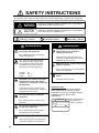
SAFETY INSTRUCTIONS
The operator must read the safety instructions before attempting to operate this equipment
WARNING
Indicates a potentially hazardous situation which, if not avoided,
could result in death or serious injury.
CAUTION
Indicates a potentially hazardous situation which, if not avoided,
can result in minor or moderate injury.
Warning, Caution
Mandatory Action
Prohibitive Action
WARNING
ELECTRICAL SHOCK HAZARD
Do not open the equipment.
Only qualified personnel should work
inside the equipment.
The antenna emits electromagnetic
radio frequency (RF) energy, which
can be harmful. Distances at which
RF radiation level of 100, 10 and 2
W/m2 are present are given below.
WARNING
Immediately turn off the power at the
switchboard if the equipment is
emitting smoke or fire.
Continued use of the equipment can
cause fire or electrical shock. Contact a
FURUNO agent for service.
Make sure no rain or water splash leaks
into the equipment.
Fire or electrical shock can result if water
leaks in the equipment.
100 W/m2: Nil
10 W/m2: 0.1 m
1.0 m
2 W/m2:
Immediately turn off the power at the
switchboard if water leaks into the
equipment or something is dropped in
the equipment.
Continued use of the equipment can
cause fire or electrical shock. Contact a
FURUNO agent for service.
Do not disassemble or modify the
equipment.
Fire, electrical shock or serious injury
can result.
Do not place liquid-filled containers on
the top of the equipment.
Fire or electrical shock can result if a
liquid spills into the equipment.
Use the proper fuse.
Use of the wrong fuse can cause fire or
permanent damage to the equipment.
ii
Do not operate the equipment with wet
hands.
Electrical shock can result.
WARNING LABEL
A warning label is attached to the AC-DC
power supply. Do not remove the label.
If the label is missing or damaged, contact
a FURUNO agent or dealer about
replacement.
WARNING
To avoid electrical shock, do not
remove cover. No user-serviceable
parts inside.
Name: Warning Label (1)
Type: 86-003-1011-1
Code No.: 100-236-231
TABLE OF CONTENTS
FOREWORD...........................................iv
SYSTEM CONFIGURATION ..................vi
PROGRAM NUMBER ...........................vii
SYSTEM OVERVIEW ...........................viii
1. OPERATION .................................... 1-1
1.1
1.2
1.3
1.4
1.5
1.6
1.7
1.8
1.9
1.10
1.11
1.12
1.13
Description of Controls ............................. 1-1
Turning the Power On and Off .................. 1-2
Adjusting Panel Dimmer and Contrast...... 1-4
Menu Overview......................................... 1-5
1.4.1
Menu operating procedure ......... 1-5
Entering Voyage-Related Data ................. 1-7
Setting CPA/TCPA .................................. 1-11
Selecting a Display ................................. 1-12
1.7.1
Plotter display........................... 1-13
1.7.2
Target list
(displaying target data) ............. 1-15
1.7.3
Dangerous (target) list .............. 1-22
1.7.4
Static data display..................... 1-22
1.7.5
Dynamic data display ............... 1-24
1.7.6
Alarm status display ................. 1-24
Messages ............................................... 1-24
1.8.1
Sending a message.................. 1-25
1.8.2
Receiving messages ................ 1-26
1.8.3
TX and RX message logs......... 1-28
Regional Operating Channels................. 1-29
1.9.1
Viewing channels, Tx power ..... 1-29
1.9.2
Displaying, editing regional operating
area status................................ 1-30
Enabling/Disabling Alarm Buzzer,
Key Beep................................................ 1-32
Long Range ............................................ 1-32
1.11.1 LR MODE (Long Range Mode) 1-32
1.11.2 MSG27 TX................................ 1-34
Pilot Plug (Option) .................................. 1-35
Viewing Initial Settings............................ 1-36
2. INLAND AIS OPERATION............... 2-1
2.1
2.2
2.3
2.4
2.5
2.6
2.7
Activating the Inland AIS........................... 2-1
Selecting AIS Mode .................................. 2-2
Entering Voyage-Related Data ................. 2-3
Static Data ................................................ 2-8
Dynamic Data ......................................... 2-10
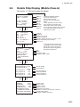
Details Ship Display (Mobile Class A)..... 2-11
Inland AIS Specific Messaging................ 2-13
2.7.1
Text message ........................... 2-13
2.7.2
ETA and RTA messages ........... 2-15
2.7.3
No. of persons message........... 2-18
2.7.4
EMMA warning message.......... 2-20
2.7.5
Water level message ................ 2-22
2.7.6
Message logs ........................... 2-22
2.8 Viewing Initial Settings............................ 2-24
2.9 Selecting Menu Language ...................... 2-25
2.10 Selecting Units of Measurement............. 2-26
2.11 Setting for Time Difference ..................... 2-26
3. MAINTENANCE,
TROUBLESHOOTING ..................... 3-1
3.1
3.2
Maintenance ............................................. 3-1
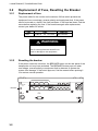
Replacement of Fuse,
Resetting the Breaker............................... 3-2
3.2.1
Replacement of fuse................... 3-2
3.2.2
Resetting the breaker ................. 3-2
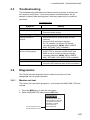
3.3 Troubleshooting........................................ 3-3
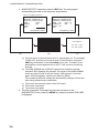
3.4 Diagnostics............................................... 3-3
3.4.1
Monitor unit test.......................... 3-3
3.4.2
Transponder test ........................ 3-5
3.4.3
Power on/off history.................... 3-7
3.4.4
Tx on/off history .......................... 3-7
3.5 Alarm Status ............................................. 3-8
3.6 Error and System Messages .................... 3-9
3.7 GPS Monitor........................................... 3-11
3.8 Displaying Sensor Status........................ 3-12
3.9 Restoring Default Settings ...................... 3-13
3.10 AIS-SART Test Indication in Target List .. 3-14
APPENDIX ...................................... AP-1
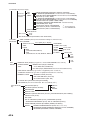
Menu Tree - Class A AIS ................................. AP-1
Menu Tree - Inland AIS ................................... AP-3
Parts List ......................................................... AP-5
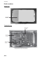
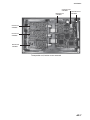
Parts Location ................................................. AP-6
Digital Interface
(IEC 61162-1 Edition 4, IEC 61162-2) ............ AP-8
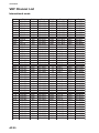
VHF Channel List .......................................... AP-20
ERI Codes..................................................... AP-22
Terminology, Units, Symbols ......................... AP-23
SPECIFICATIONS ............................ SP-1
INDEX .................................................IN-1
Declaration of Conformity
iii
FOREWORD
A Word to the Owner of the FA-150
FURUNO Electric Company thanks you for purchasing the FA-150 UAIS Transponder. We
are confident you will discover why the FURUNO name has become synonymous with
quality and reliability.
Since 1948, FURUNO Electric Company has enjoyed an enviable reputation for quality
and reliability throughout the world. This dedication to excellence is furthered by our
extensive global network of agents and dealers.
Your equipment is designed and constructed to meet the rigorous demands of the marine
environment. However, no machine can perform its intended function unless properly
operated and maintained. Please carefully read and follow the operation and maintenance
procedures in this manual.
We would appreciate feedback from you, the end-user, about whether we are achieving
our purposes.
Thank you for considering and purchasing FURUNO.
Features
The FA-150 is a universal AIS (Automatic Identification System) for open sea and inland
waterways, capable of exchanging navigation and ship data between own ship and other
ships or coastal stations. It complies with IMO MSC.74(69) Annex 3, A.694, ITU-R
M.1371-4 and DSC ITU-R M.825. It also complies with IEC 61993-2 (Type testing
standard), IEC 60945 (EMC and environmental conditions).
The FA-150 consists of VHF and GPS antennas, a transponder unit, a monitor unit, and
several associated units. The transponder contains a VHF transmitter, two TDMA
receivers on two parallel VHF channels, a DSC channel 70 receiver, interface,
communication processor, and internal GPS receiver. The internal GPS is a 12-channel
all-in-view receiver with a differential capability, and provides UTC reference for system
synchronization to eliminate clash among multiple users. It also gives position, COG and
SOG when the external GPS fails.
iv
The main features are
• Safety of navigation by automatically exchanging navigational data between ships and
between ship and coast
• Static data:
- MMSI (Maritime Mobile Service Identity)
- IMO number (where available)
- Call sign & name
- Length and beam
- Type of ship
- Location of position-fixing antenna on the ship
• Dynamic data:
- Ship’s position with accuracy indication and integrity status
- Universal Time Coordinated (UTC)
- Course over ground (COG)
- Speed over ground (SOG)
- Heading
- Rate of turn (ROT) where available
• Voyage-related data
- Ship’s draught
- Navigation status (manual input)
- Hazardous cargo (type)
- Destination and ETA (at master’s discretion)
•
•
•
•
•
•
•
Short safety-related messages, free messages
LCD panel satisfies the IMO minimum requirements plus simple plotting modes
Interfaces for radar, ECDIS, PC for future networking expansion
GPS/VHF combined antenna for easy installation available
CPA/TCPA alarm
Built-in GPS receiver for UTC synchronization and backup position-fixing device
The Inland AIS feature is based on CCNR (Vessel Tracking and Tracing Standard for
Inland Navigation). Inland AIS receives and sends SOLAS AIS information, and
interfaces automatic data input such as blue sign, draught (in centimeters), air draught
(height from waterline), hazardous cargo blue cone indication, euro ship identifier and
inland ship type. Further, the inland AIS sends ETA (Estimated Time of Arrival) to lock,
bridge, terminal, etc. and displays response as RTA (Requested Time of Arrival) from
the lock, bridge or terminal. Information receivable from land stations include EMMA
warning, water level data, etc.
v
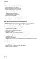
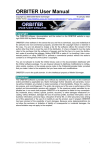
SYSTEM CONFIGURATION
Either
GPS antenna
GSC-001
GPA-017S
VHF antenna
GPS/VHF
combined antenna
GVA-100
MONITOR UNIT
FA-1502
(two units may
be connected)
Distributor unit
DB-1
UNIVERSAL AIS
MENU
ENT
DISP
DIM
NAV
STATUS
FA-150
PWR
12-24 VDC
TRANSPONDER UNIT
FA-1501
External display, Pilot plug,
NavNet2, Sensor
Alarm system
PC, Beacon receiver
LAN
Blue Sign
: Standard
Power supply
PR-240
: Option
: Local supply
100/110/115/200/
220/230 VAC
1φ, 50/60Hz
vi
24 VDC
12-24 VDC
GSC-001
GVA-100
FA-1501
FA-1502
DB-1
PR-240
Exposed to the weather
Exposed to the weather
Protected from the weather
Protected from the weather
Protected from the weather
Protected from the weather
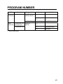
PROGRAM NUMBER
PCB
CPU
(24P0062)
MAIN
(24P0035)
Location
Monitor Unit
Transponder Unit
GPS Receiver
Transponder Unit
Program No.
2450021 (Prog)
2450020 (Boot)
Version No.
Date of Modification
01.**
01.**
02.**
02.**
September 2009
2450021 (Prog)
03.**
May 2012
2450018
485026
01.**
40**
02.**
September 2009
03.**
May 2012
**: Minor Modification
vii
SYSTEM OVERVIEW
System overview
The Automatic Identification System (AIS) was originally developed to aid the Vessel
Traffic Services (VTS) by use of a VHF transponder working on Digital Selective Call
(DSC) at VHF CH70, and is still in use along the UK coastal areas and others. Some time
later the IMO developed a Universal AIS using the new sophisticated technology called
Self-Organized Time Division Multiple Access (SOTDMA) based on a VHF Data Link
(VDL).
The system operates in three modes – autonomous (continuous operation in all areas),
assigned (data transmission interval remotely controlled by authority in traffic monitoring
service) and polled (in response to interrogation from a ship or authority). It is
synchronized with GPS time to avoid conflict among multiple users (IMO minimum 2000
reports per minute and IEC requires 4500 reports on two channels). The VHF channels
87B and 88B are commonly used and in addition there are local AIS frequencies.
Shipborne AIS transponders exchange various data as specified by the IMO and ITU on
either frequency automatically set up by the frequency management telecommand
received by the DSC receiver on ship.
AIS-fitted AtoN broadcasts its
identification, type of operation,
location, displacement, etc. at
3-min intervals or at a reporting
rate designated by the
Administration authorities.
Transponder
Aids to
Navigation
(AtoN)
VTS Center transmits TDMA CH
management message including
code, type, position, etc. of buoys
every 3 min, and the AtoN broadcasts
these messages for ships.
VTS center
The VTS center transmits a command on
frequency assignment, slots, report rate,
VHF output power, channel spacing, etc.
(Assigned mode)
Transponder
Transponder
Static and Dynamic information incl.
MMSI, Name, POSN, HDG, COG, SOG
Interrogation and Response
Own ship
Ship 1
All ships broadcast Static and Dynamic information (autonomous and
continuous mode). If OS wants to know information about ship 1, OS shall
send an interrogation in polling mode; then ship 1 will transmit her
response on the same VHF channel without operator intervention.
AIS system
viii
Not all ships carry AIS
The Officer of the Watch (OOW) should always be aware that other ships, and in particular
leisure craft, fishing boats and warships, and some coastal shore stations (including
Vessel Traffic Service centers) might not be fitted with AIS.
The OOW should also be aware that AIS fitted on other ships as a mandatory carriage
requirement might be switched off by the master if its use might compromise the security
of the vessel. Thus, users are therefore cautioned to always bear in mind that information
provided by AIS may not be giving a complete or correct “picture” of shipping traffic in their
vicinity.
Use of AIS in collision avoidance
As an anti-collision aid, the AIS has the following advantages over radar:
• Information provided in near real-time
• Capable of instant presentation of target course alterations
• Not subject to target swap
• Not subject to target loss in clutter
• Not subject to target loss due to abrupt maneuvers
• Able to "detect" ships within VHF/FM coverage, including in some circumstances,
around bends and behind islands.
When using the AIS for anti-collision purposes it is important to remember that the AIS is
an additional source of navigation information. It does not replace other navigational
systems. The AIS may not be giving a complete or correct “picture” of shipping traffic in its
vicinity.
The use of the AIS does not negate the responsibility of the OOW to comply with all
collision regulation requirements, especially the maintaining of a proper look-out. The
prudent navigator uses all aids available to navigate the ship.
Erroneous information
Erroneous information implies a risk to other ships as well as your own. Poorly configured
or improperly calibrated sensors might lead to incorrect information being transmitted. It is
the user’s responsibility to ensure that all information entered into the system is correct
and up to date.
ix
This page intentionally left blank.
x
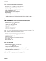
1.
OPERATION
1.1
Description of Controls
1
3
2
4
UNIVERSAL AIS
MENU
ENT
DISP
DIM
NAV
STATUS
FA-150
5
PWR
7
8
6
1
LCD Screen:
Displays various data.
2
CursorPad:
Shifts cursor; chooses menu items and options;
selects alphanumeric data.
3
MENU key:
Opens the menu.
4
ENT key:
Terminates keyboard input; changes screen.
5
DISP key:
Chooses a display screen; closes menu.
6
DIM key:
Adjusts panel dimmer and LCD contrast.
7
NAV STATUS key: Displays NAV STATUS menu, which contains voyage-related data.
8
PWR key:
Turns the power on and off.
Notice: The nominal viewing distance is 50 cm.
1-1
1. OPERATION
1.2
Turning the Power On and Off
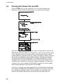
Press the PWR key to turn the equipment on or off. When powered, the
equipment sounds a beep then proceeds in the sequence shown below.
The startup screen displays the program version number and the results of the
ROM, RAM and backup data test, showing OK or “NG” (No Good) as the result.
If “NG” appears for any of the check result, try resetting the power to restore
normal operation. If that does not work, contact your dealer for advice. After the
startup test is completed the plotter display appears, showing the messages
“NO OWN SHIP POSITION AVAILABLE.” and “NOW INITIALIZING.” These
messages mean that position data has not yet arrived and the transponder is
initializing itself, respectively. When both messages disappear, the equipment
is ready for use. If the message “ENTER MMSI!” appears, the vessel’s MMSI
has not been registered in the equipment. Enter MMSI.
If there is no response from the transponder unit or AIS symbols do not appear,
the message “COMMUNICATION ERROR” appears on the screen. Press any
key to erase the message. Check if the transponder unit is powered. Also
check the connection between the monitor unit and the transponder unit.
1-2
1. OPERATION
The FA-150 should be powered while underway or at anchor. The master may
switch off the AIS if he believes that the continual operation of the AIS might
compromise the safety or security of his ship. The AIS should be restarted
once the source of danger has gone.
The equipment transmits own ship static data within two minutes of start-up
and it is transmitted at six-minute intervals thereafter. Static data includes
MMSI number, IMO number, call sign, ship name, ship length and width, ship
type and GPS antenna position.
In addition to static data, ship’s dynamic data is also transmitted. This data
includes position with quality indication, SOG, COG, rate of turn, heading, etc.
Dynamic data is transmitted every 2 s to 3 min depending on ship’s speed and
course change. Voyage-related data, such as ship’s draft, hazardous cargo,
destination and estimated time of arrival, are transmitted at six-minute
intervals.
The FA-150 starts receiving data from AIS-equipped ships as soon as it is
turned on, and those ships’ location are shown on the plotter display with the
AIS symbol. (To learn more about the plotter display, see section 1.7.) With
connection of a radar or ECDIS, the AIS target symbols may be overlaid on the
radar or ECDIS.
Note 1: If no navigation sensor is installed or a sensor such as a gyrocompass
has failed, the AIS automatically transmits “not available” data to AIS-equipped
ships.
Note 2: The reporting intervals are as follows:
Ship’s dynamic conditions and nominal reporting interval
Ship’s navigation status
Nominal reporting interval
Ship at anchor and not moving faster than 3 kn
3 minutes
Ship at anchor and moving faster than 3 kn
10 seconds
Ship speed 0-14 kn
10 seconds
Ship speed 0-14 kn and changing course
3 1/3 seconds
Ship speed 14-23 kn
6 seconds
Ship speed 14-23 kn and changing course
2 seconds
Ship speed faster than 23 kn
2 seconds
Ship speed faster than 23 kn and changing course
2 seconds
1-3
1. OPERATION
1.3
Adjusting Panel Dimmer and Contrast
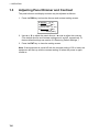
The panel dimmer and display contrast may be adjusted as follows:
1. Press the DIM key to show the dimmer and contrast setting screen.
DIMMER
( 0 ~8 )
4
C O N T R A S T ( 0 ~6 3 )
44
EXIT: [ENT]
2. Use ▲ or ▼ to adjust the panel dimmer; ◄ or ► to adjust the contrast.
(The default dimmer and contrast settings are 4 and 45, respectively. To
restore default settings see section 3.9 Restoring Default Settings.)
3. Press the ENT key to close the setting screen.
Note: If the equipment is turned off with the contrast setting of 35 or lower, the
equipment will start up with the contrast setting 36 when the power is again
turned on.
1-4
1. OPERATION
1.4
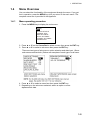
Menu Overview
You can select the functionality of the equipment through the menu. If you get
lost in operation, press the MENU key until you return to the main menu. The
complete menu tree is provided in the Appendix.
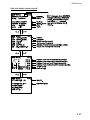
1.4.1
Menu operating procedure
1. Press the MENU key to display the main menu.
[MENU]
MSG
SENSOR STATUS
INTERNAL GPS
USER SETTINGS
INITIAL SETTINGS
CHANNEL SETTINGS
DIAGNOSTICS
2. Press ▲ or ▼ on the CursorPad to select a menu then press the ENT key.
3. Press ▲ or ▼ to select a sub-menu then press the ENT key.
There are two types of sub-menus: option selection and data input. (Some
sub-menus combine both.) Below are examples of each type of sub-menu.
4. Press ▲ or ▼ to select a menu item then press the ENT key.
5. Depending on the sub-menu selected, select an option or enter
alphanumeric data.
1-5
1. OPERATION
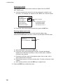
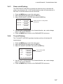
Selecting an option
The example below shows how to select an option from the USER
SETTINGS menu.
a) A window showing the options for the item selected is overlaid on the
sub-menu. For example, the options for KEY BEEP are as shown below.
[USER SETTINGS]
KEY BEEP
: ON
ALARM BUZZER : ON
ON
AUTO SORT
: ON
OFF
DISP SART TEST : ON
LONG RANGE
RECEIVED MSG
CPA/TCPA ALARM
Options window
NOTE: For INLAND AIS mode,
the USER SETTINGS
menu has two pages.
See section 2.9 to 2.11.
b) Press ▲ or ▼ to select option desired then press the ENT key.
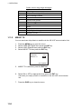
Entering alphanumeric data
The example below shows how to enter numeric data on the
DRAUGHT&PERSONS sub-menu, which is on the NAV STATUS menu.
[DRAUGHT&PERSONS] W
DRAUGHT:
00.0 m
NO. OF PERSONS:
0
Cursor
a) Select DRAUGHT and press the ENT key.
b) Press ▲ or ▼ to select appropriate numeric. Pressing ▲ displays
alphanumeric characters cyclically in order of blank space, alphabet,
numerals, and symbols.
c) Press ► to shift the cursor to the adjacent place, then use ▲ or ▼ to
select alphanumeric character.
d) Repeat steps b) and c) to finish entering data. To erase a character, insert
a space.
e) After entering all data, press the ENT key to register input.
6. Press the DISP key to close the menu.
1-6
1. OPERATION
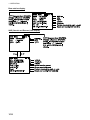
1.5
Entering Voyage-Related Data
There are six items on the NAV STATUS menu that you will need to enter at
the start of a voyage.
• Navigation status
• Cargo type
• Arrival time
• Destination
• No. of persons
• Draught
1. Press the NAV STATUS key to open the NAV STATUS menu.
2. If your navigation status is different from that shown, follow the procedure
below. If it is the same as shown, go to step 3.
a) Press the ENT key.
b) Press ▲ or ▼ to select appropriate status then press the ENT key. Refer to
the data below to select appropriate nav status.
00:
01:
02:
03:
04:
05:
06:
07:
08:
09:
10:
11:
12:
13:
14:
15:
UNDER WAY USING ENGINE
AT ANCHOR
NOT UNDER COMMAND
RESTRICTED MANEUVERABILITY
CONSTRAINED BY HER DRAUGHT
MOORED
AGROUND
ENGAGED IN FISHING
UNDER WAY SAILING
1
RESERVED FOR HIGH SPEED CRAFT (HSC)*
2
RESERVED FOR WING IN GROUND (WIG)*
RESERVED FOR FUTURE USE
RESERVED FOR FUTURE USE
RESERVED FOR FUTURE USE
AIS-SART (ACTIVE)
NOT DEFINED = DEFAULT (ALSO USED BY AIS-SART UNDER TEST)
*1: RESERVED FOR FUTURE AMENDMENT OF NAVIGATIONAL STATUS
FOR SHIPS CARRYING DG, HS, OR MP, OR IMO HAZARD OR
POLLUTANT CATEGORY C, HIGH SPEED CRAFT (HSC)
*2: RESERVED FOR FUTURE AMENDMENT OF NAVIGATIONAL STATUS
FOR SHIPS CARRYING DANGEROUS GOODS (DG), HARMFUL
SUBSTANCES (HS) OR MARINE POLLUTANTS (MP), OR IMO HAZARD
OR POLLUTANT CATEGORY A, WING IN GRAND (WIG)
3. Press ► to show the DESTINATION sub-menu.
1-7
1. OPERATION
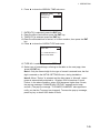
4. NEW is selected; press the ENT key.
[DESTINATION]
ENTER A NEW
DESTINATION
QUIT:[NAV STATUS]
NAV STATUS menu, DESTINATION sub-menu, destination input
5. Press the ENT key. Enter destination then press the ENT key. You can use
up to 20 alphanumeric characters (\, ^, !, ,, $, and * count as three
characters), and enter 20 destinations. (For how to enter alphanumeric
characters, see “Entering alphanumeric data” on page 1-6.)
PROCESSING DESTINATIONS
If you have already registered some destinations, the DESTINATION
sub-menu looks something like the one below. From this screen you can
select, edit or delete destinations.
[DESTINATION]
COTE D'IVOIRE
Current destination
*************(0/3)
[NEW?]
COTE D'IVOIRE
SAN FRANCISCO
SEATTLE
Destination list
1) Select appropriate destination then press the ENT key to show the options
window below.
SELECT
EDIT
DELETE
2) Select SELECT, EDIT or DELETE as appropriate then press the ENT key.
Do one of the following according to your objective.
SELECT: Select a destination.
EDIT: Press the ENT key twice then edit the destination.
DELETE: The prompt below appears. Press to select
YES; press the ENT key.
DESTINATION DELETE.
ARE YOU SURE?
YES
NO
1-8
1. OPERATION
6. Press ► to show the ARRIVAL TIME sub-menu.
[ARRIVAL TIME]
25/APR
DATE [UTC]:
TIME[UTC]:
0:00
7. DATE[UTC] is selected; press the ENT key.
8. Enter the date of arrival then press the ENT key.
9. TIME[UTC] is selected; press the ENT key.
10. Enter the estimated time of arrival, in 24-hour notation, then press the ENT
key.
11. Press ► to show the CARGO TYPE sub-menu.
[CARGO TYPE]
TYPE NO.:
00
**** TYPE DETAIL****
NOT AVAILABLE
12. TYPE NO. is selected; press the ENT key.
13. Select type of vessel/cargo, referring to the table on the next page, then
press the ENT key.
Note 1: Only the second digit for the type of vessel is entered here; the first
digit is entered on the INITIAL SETTINGS menu, during installation.
Note 2: When “Tanker” is selected and the Nav status is “Moored”, output
power is automatically switched to 1 W when SOG is less than 3 knots.
Further, in the above condition, when SOG becomes higher than 3 knots,
the pop-up message “CHANGE NAV STATUS?” appears and a beep
sounds. (The pop-up message “TX POWER CHANGED” also appears to
notify you that the Tx power has changed). To erase the pop-up message,
press any key or lower SOG below 3 knots.
1-9
1. OPERATION
10
11
12
13
14
15
16
17
18
19
20
21
22
23
24
25
26
27
28
29
30
31
32
33
34
35
36
37
38
39
40
41
42
43
44
45
46
47
48
49
50
51
52
53
54
55
56
57
58
59
FUTURE USE
FUTURE USE
FUTURE USE
FUTURE USE
FUTURE USE
FUTURE USE
FUTURE USE
FUTURE USE
FUTURE USE
FUTURE USE
WIG
WIG
WIG
WIG
WIG
WIG
WIG
WIG
WIG
WIG
FISHING
TOWING
ALL SHIPS OF THIS TYPE
CARRYING DG, HS, OR MP( )
CARRYING DG, HS, OR MP(Y)
CARRYING DG, HS, OR MP(Z)
CARRYING DG, HS, OR MP(OS)
FUTURE USE
FUTURE USE
FUTURE USE
FUTURE USE
NONE
ALL SHIPS OF THIS TYPE
CARRYING DG, HS, OR MP(X)
CARRYING DG, HS, OR MP(Y)
CARRYING DG, HS, OR MP(Z)
CARRYING DG, HS, OR MP(OS)
FUTURE USE
FUTURE USE
FUTURE USE
FUTURE USE
NONE
60 PASSENGER SHIPS ALL SHIPS OF THIS TYPE
61 PASSENGER SHIPS CARRYING DG, HS, OR MP(X)
62 PASSENGER SHIPS CARRYING DG, HS, OR MP(Y)
63 PASSENGER SHIPS CARRYING DG, HS, OR MP(Z)
64 PASSENGER SHIPS CARRYING DG, HS, OR MP(OS)
65 PASSENGER SHIPS FUTURE USE
66 PASSENGER SHIPS FUTURE USE
67 PASSENGER SHIPS FUTURE USE
68 PASSENGER SHIPS FUTURE USE
69 PASSENGER SHIPS NONE
70 CARGO SHIPS
ALL SHIPS OF THIS TYPE
71 CARGO SHIPS
CARRYING DG, HS, OR MP(X)
72 CARGO SHIPS
CARRYING DG, HS, OR MP(Y)
73 CARGO SHIPS
CARRYING DG, HS, OR MP(Z)
74 CARGO SHIPS
CARRYING DG, HS, OR MP(OS)
75 CARGO SHIPS
FUTURE USE
76 CARGO SHIPS
FUTURE USE
77 CARGO SHIPS
FUTURE USE
78 CARGO SHIPS
FUTURE USE
79 CARGO SHIPS
NONE
80 TANKER
ALL SHIPS OF THIS TYPE
81 TANKER
CARRYING DG, HS, OR MP(X)
LENGTH OF THE TOW EXCEEDS 200M OR BREADTH EXCEEDS 25M 82 TANKER
CARRYING DG, HS, OR MP(Y)
ENGAGED IN DREDGING OR UNDERWATER OPERATIONS 83 TANKER
CARRYING DG, HS, OR MP(Z)
ENGAGED IN DIVING OPERATIONS
84 TANKER
CARRYING DG, HS, OR MP(OS)
ENGAGED IN MILITARY OPER ATIONS
85 TANKER
FUTURE USE
SAILING
86 TANKER
FUTURE USE
PLEASURE CRAFT
87 TANKER
FUTURE USE
FUTURE USE
88 TANKER
FUTURE USE
FUTURE USE
89 TANKER
NONE
HSC
ALL SHIPS OF THIS TYPE
90 OTHER TYPE OF SHIP ALL SHIPS OF THIS TYPE
HSC
CARRYING DG, HS, OR MP(X)
91 OTHER TYPE OF SHIP CARRYING DG, HS, OR MP(X)
HSC
CARRYING DG, HS, OR MP(Y)
92 OTHER TYPE OF SHIP CARRYING DG, HS, OR MP(Y)
HSC
CARRYING DG, HS, OR MP(Z)
93 OTHER TYPE OF SHIP CARRYING DG, HS, OR MP(Z )
HSC
CARRYING DG, HS, OR MP(OS)
94 OTHER TYPE OF SHIP CARRYING DG, HS, OR MP(OS)
HSC
FUTURE USE
95 OTHER TYPE OF SHIP FUTURE USE
HSC
FUTURE USE
96 OTHER TYPE OF SHIP FUTURE USE
HSC
FUTURE USE
97 OTHER TYPE OF SHIP FUTURE USE
HSC
FUTURE USE
98 OTHER TYPE OF SHIP FUTURE USE
HSC
NONE
99 OTHER TYPE OF SHIP NONE
PILOT
WIG: Wing in ground
SEARCH AND RESCUE VESSELS
HSC: High speed craft
TUGS
PORT TENDERS
DG: Dangerous goods
VESSELS WITH ANTI-POLL UTION FACILITIES OR EQUIPMENT
LAW ENFORCEMENT VESSELS
SPARE-FOR ASSIGNMENTS TO LOCAL VESSELS
SPARE-FOR ASSIGNMENTS TO LOCAL VESSELS
MEDICAL TRANSPORTS
SHIPS & AIRCRAFT OF STATES NOT PARTIES TO AN ARMED CONFLICT
HS: Harmful substances
MP: Marine pollutants
0-9: Undefined
14. Press ► to display the
DRAUGHT&PERSONS sub-menu.
15. DRAUGHT is selected; press the ENT key.
16. Enter ship’s draught (setting range: 0-25.5(m))
then press the ENT key.
17. NO. OF PERSONS is selected; press the
ENT key.
18. Enter total number of persons onboard
(setting range: 0-8191) then press the ENT
key. Enter 8191 for total greater than 8190.
19. Press the DISP key to close the menu.
1-10
[DRAUGHT&PERSONS] W
DRAUGHT:
0.0 m
NO. OF PERSONS:
0
1. OPERATION
1.6
Setting CPA/TCPA
Set the CPA (Closest Point of Approach) and TCPA (Time to Closest Point of
Approach) range for which you want to be alerted to AIS targets which can be
on a collision course. When a ship’s CPA and TCPA are lower than that set
here, the buzzer sounds (if active) and the message COLLISION ALARM
appears.
1. Press the MENU key to open the main menu.
2. Select USER SETTINGS then press the ENT key.
3. Select CPA/TCPA ALARM then press the ENT key.
[CPA/TCPA ALARM]
CPA
: 6.00 NM
TCPA
: 60 min
ALARM MODE : ON
ALARM BUZZER : ON
QUIT[MENU]
4.
5.
6.
7.
8.
9.
CPA is selected; press the ENT key.
Enter CPA (setting range: 0-6.00 NM) then press the ENT key.
TCPA is selected; press the ENT key.
Enter TCPA (setting range: 0-60 min) then press the ENT key.
ALARM MODE is selected; press the ENT key.
Select ON to activate the CPA/TCPA alarm; OFF to deactivate it. Press the
ENT key.
10. ALARM BUZZER is selected; press the ENT key.
11. Select ON to enable the CPA/TCPA audio alarm, or OFF to disable it. Press
the ENT key.
12. Press the DISP key to close the menu.
1-11
1. OPERATION
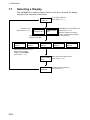
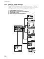
1.7
Selecting a Display
Use the DISP key to select a display. Each time the key is pressed, the display
changes in the sequence shown below.
PLOTTER
DISPLAY
TARGET LIST
(See section 1.7.2. )
TARGET LIST
DANGEROUS
LIST
Switch between these
displays with , .
OWN STATIC
DATA 1
OWN STATIC
DATA 2
PLOTTER DISPLAY
(See section 1.7.1.)
OWN STATIC
DATA 3
DANGEROUS (TARGET) LIST
(See section 1.7.3.)
When a dangerous target
exists, the dangerous target
list has priority.
OWN STATIC
DATA 4
OWN STATIC
DATA 5
OWN SHIP'S STATIC DATA
Switch among these
displays with
.
(See section 1.7.4.)
OWN SHIP'S DYNAMIC DATA
OWN DYNAMIC
(See section 1.7.5.)
DATA
ALARM
STATUS
1-12
ALARM STATUS DISPLAY
(See section 3.5.)
1. OPERATION
1.7.1
Plotter display
The plotter display, which automatically appears after the power-on sequence,
shows the name, heading, SOG, COG, CPA and TCPA of AIS-equipped ships,
AIS-SARTs, etc. within the range selected. The number of dangerous targets is
also indicated.
Data for ship target
A target marker (hollow triangle) indicates the presence of a vessel equipped
with AIS in a certain location and course. To find detailed information about a
vessel, see section 1.7.2.
If two or more targets occupy a similar position, the display priority order is
selected target, AIS-SART and ship target.
Data for AIS-SART
1-13
1. OPERATION
Operations on the plotter display
1. Press the DISP key to show the plotter display.
2. Use ▼ or ▲ to select the range. The available ranges are (in nm) 0.125,
0.25, 0.5, 0.75, 1.5, 3, 6, 12, and 24.
3. To find a target’s data, see section 1.7.2.
Note 1: A target is declared a lost target under the conditions shown in the
table below. A target is erased from the screen 6 minutes and 40 seconds after
it is declared a lost target.
Ship’s navigation status
Target declared as
lost target after;
Class A
Ship at anchor or moored and not moving faster than 3 kn
Ship at anchor or moored and moving at more than 3 kn
0-14 kn speed
0-14 kn speed with course change
14-23 kn speed
14-23 kn speed with course change
Speed higher than 23 kn
10 minutes
50 seconds
50 seconds
50 seconds
30 seconds
30 seconds
10 seconds
Speed higher than 23 kn with course change
10 seconds
Class B
Speed over ground less than 2 kn
10 minutes
Speed over ground 2 kn or higher
150 seconds
Note 2: When a target’s CPA and TCPA are lower than set in section 1.6, the
audio alarm sounds (if active). Press any key to silence the audio alarm. Take
suitable measures to avoid collision.
Note 3: "DNGR" (DANGER) appears at the end of the HDG line when a
target's CPA and TCPA are lower than the CPA and TCPA alarm settings.
Further, when a target becomes a lost target, “LOST” appears at the end of the
HDG line.
1-14
1. OPERATION
1.7.2
Target list (displaying target data)
1. At the plotter display, press the DISP key to show the TARGET LIST, which
lists all AIS targets and AIS-SARTs being detected by the FA-150.
Note 1: The dangerous target list appears when there are dangerous
targets. You can switch to the target list by pressing ◄.
Note 2: If there is no data for the target selected, the message NO SEL
appears. Hit any key to escape.
Note 3: Targets are automatically sorted in range order (closest to furthest)
when no key is operated for 30 seconds. Target order is then updated every
five seconds.
Note 4: When AUTO SORT on the USER SETTINGS menu is OFF, the
range and bearing to a target are updated. However, target order is not
updated. To do this, press ◄, and targets are sorted in range order. “NOW
SORTING” is shown while sorting.
Note 5: To select a target on the plotter display, press ◄ or ► to select the
target then press the ENT key. Press ► to select from nearest to furthest;
◄ to select from furthest to nearest. The display then looks something like
the one shown at the top of the next page. If you wish to see other target
data, go to step 3 below.
Note 6: The information source is specified from obtained MMSI and ship's
name of an AIS target.
2. Use ▼ or ▲ to select the target whose data you wish to view then press
the ENT key. The display then looks something like one of the displays
shown on the next several pages, according to type of target.
3. Use ▼ or ▲ to scroll the display to see other data.
1-15
1. OPERATION
Ship info display, mobile class A
1-16
1. OPERATION
Ship info display, mobile class B
1-17
1. OPERATION
Base station display
SAR (Search and Rescue) info display
1-18
1. OPERATION
AIS-SART info display
DNGR appears when CPA/TCPA
of target is less than CPA/TCPA
setting. If no signal is received
from target, LOST appears.
6:40 later the target's data is
erased.
[SART INFO]
1/3
MMSI : 970010001
STATUS: SART ACTIVE
RNG
BRG
CPA
TCPA
: 10.65 NM
: 9.4°
: 8.83NM
: 43' 06°
[SART INFO]
2/3
LAT : 34°03.5442'N
LON : 134°30.3883'E
SOG : 17.8kn
COG : 213.5°
HDG : 213°
ROT : R 0.1°/min
PA : H
[SART INFO]
NAV STATUS: 14
***STATUS DETAIL***
AIS SART (ACTIVE)
MMSI no.
Status (SART ACTIVE (NAV STATUS: 14),
SART TEST (NAV STATUS: 15))
Range
Bearing
CPA
TCPA
Latitude
Longitude
Speed over the ground
Course over the ground
Heading
Rate of turn
Position Accuracy (H, High, L, Low)
3/3
Navigation status
14: SART ACTIVE, 15: SART TEST
Status detail
1-19
1. OPERATION
AtoN (Aid to Navigation) info display
1-20
1. OPERATION
The table below shows all the AtoN types and names that may appear on the
AtoN INFO display.
A to N type and name
Type
0
1
2
3
4
5
6
7
8
9
10
11
12
13
14
15
16
17
18
19
20
21
22
23
24
25
26
27
28
29
30
31
Name of AtoN
DEFAULT, TYPE OF A TO N NOT SPECIFIED
REFERENCE POINT
RACON
OFF SHORE STRUCTURE
SPARE
LIGHT, WITHOUT SECTORS
LIGHT, WITH SECTORS
LEADING LIGHT FRONT
LEADING LIGHT REAR
BEACON, CARDINAL N
BEACON, CARDINAL E
BEACON, CARDINAL S
BEACON, CARDINAL W
BEACON, PORT HAND
BEACON, STARBOARD HAND
BEACON, PREFERRED CHANNEL PORT HAND
BEACON, PREFERRED CHANNEL STARBOARD HAND
BEACON, ISOLATED DANGER
BEACON, SAFE WATER
BEACON, SPECIAL MARK
CARDINAL MARK N
CARDINAL MARK E
CARDINAL MARK S
CARDINAL MARK W
PORT HAND MARK
STARBOARD HAND MARK
PREFERRED CHANNEL PORT HAND
PREFERRED CHANNEL STARBOARD HAND
ISOLATED DANGER
SAFE WATER
SPECIAL MARK
LIGHT VESSEL / LANBY / RIGS
1-21
1. OPERATION
1.7.3
Dangerous (target) list
You can easily find dangerous ships whose CPA and TCPA are lower than the
CPA and TCPA alarm settings.
1. At the plotter display, press the DISP key to show the Target List (see
section 1.7.2).
Note 1: If the target list appears, press ► to show the dangerous list.
Note 2: Targets are automatically sorted by TCPA when no key is operated
for 30 seconds. Target order is then updated every five seconds.
2. Press ► to show the Dangerous List.
3. To find detailed information about a dangerous target, use ▼ or ▲ to select
the target then press the ENT key.
4. To change page: ▼ or ► to go forward; ▲ or ◄ to go back.
Note 1: The message “LOST” appears at the top of the Dangerous List when
no AIS signal is received from the target selected.
Note 2: CPA and TCPA are automatically updated when AUTO SORT on the
USER SETTINGS menu is OFF, however target order is not updated. To do
this, press ◄, and the targets are sorted in TCPA order.
“NOW SORTING” is shown while sorting.
1.7.4
Static data display
The OWN STATIC DATA display shows, on five pages, your ship’s static data,
which includes MMSI, call sign and name, IMO number, type of ship and
location of position-fixing antenna. This data should be checked once per
voyage or once per month whichever is shorter. Data may be changed only on
the authority of the master.
1. At the plotter display, press the DISP key twice to show “OWN STATIC
DATA”. See the next page.
2. To view other own static data: ▼ or ► to go forward, ▲ or ◄ to go back.
See the illustration on the next page for own ship’s static data examples.
1-22
1. OPERATION
1-23
1. OPERATION
1.7.5
Dynamic data display
The OWN DYNAMIC DATA display shows your ship’s dynamic data, which
includes time, date, ship’s position, SOG, COG, heading, ROT, position
accuracy, and RAIM use.
The Officer of the Watch should periodically check position, SOG and sensor
information for quality.
At the plotter display, press the DISP key three times to show the OWN
DYNAMIC DATA display.
1.7.6
Alarm status display
The alarm status display shows the date and time alarms were violated. For
further details, see section 3.5.
1.8
Messages
You may send and receive messages via VHF channels , to a specified MMSI
or all AIS-equipped ships in the area. Messages can be sent to warn of safety
of navigation; for example, an iceberg sighted. Routine messages are also
permitted.
Short safety-related messages are only an additional means to broadcast
safety information. They do not remove the requirements of the GMDSS.
When a message is received, the equipment beeps and the indication
“MESSAGE” appears. The contents of the message may be viewed on the RX
log.
1-24
1. OPERATION
1.8.1
Sending a message
1. Press the MENU key to open the main menu.
2. Use ▼ or ▲ to select MSG then press the
ENT key.
3. CREATE MSG is selected; press the ENT
key. (For Inland AIS, additionally select
CREATE MSG then press the ENT key.)
4. SET MSG TYPE is selected; press the ENT
key.
5. ADRS TYPE is selected; press the ENT
key.
[MSG]
CREATE MSG
TX LOG
RX LOG
[CREATE MSG]
SET MSG TYPE
SET MSG
SEND MSG
[SET MSG TYPE]
ADRS TYPE: BROAD CAST
MMSI
:--------MSG TYPE : NORMAL
CHANNEL: ALTERNATE
RETRY TIMES: MMS
BROAD CAST
ADRS CAST
6. Select ADRS CAST to send a message to a specific AIS-equipped ship, or
BROAD CAST to send a message to all AIS-equipped ships within
broadcasting range. Press the ENT key.
7. For BROAD CAST, go to step 8. For ADRS CAST, “MMSI” is selected;
press the ENT key, enter MMSI number of the vessel that you want to
receive your message, then press the ENT key.
8. MSG TYPE is selected; press the ENT key.
SAFETY
NORMAL
9. Select message type: NORMAL (message other than safety) or SAFETY
(important navigational or meteorological warning). Press the ENT key.
10. CHANNEL is selected; press the ENT key.
ALTERNATE
BOTH A & B
A
B
11. Select which channel to transmit your message over then press the ENT
key.
1-25
1. OPERATION
12. RETRY TIMES is selected; press the ENT key. If the ADRS TYPE is
BROADCAST go to step 14.
13. For ADRS CAST, enter the number of times to re-transmit a message (0-3)
then press the ENT key.
14. Press the MENU key to return to the CREATE MSG sub-menu.
15. Select SET MSG then press the ENT key.
*: Number of characters available with each message type for
Class A, SOLAS is as follows:
NORMAL message with BROAD-CAST : 156 characters
NORMAL message with ADDRESS-CAST : 151 characters
SAFETY message with BROAD-CAST
: 161 characters
SAFETY message with ADDRESS-CAST : 156 characters
[SET MSG]
01(151)* [DIM]HOLD:CLEAR
Number of characters used/available
16. Use the CursorPad to enter your message.
17. Press the ENT key to return to the CREATE MSG sub-menu.
18. Select SEND MSG then press the ENT key.
SEND MESSAGE.
The prompt shown right appears.
ARE YOU SURE?
YES
NO
19. Press ◄ to select YES then press the ENT key to send your message.
Message status is shown as follows:
AIS message status messages and their meanings
Message
NOW SENDING.
SEND MESSAGE COMPLETE.
PRESS ANY KEY
SEND MESSAGE UNSUCCESSFUL.
PRESS ANY KEY
SEND MESSAGE UNSUCCESSFUL.
MMSI: XXXXXXXXX
PRESS ANY KEY
NOW WAITING RESPONSE.
PRESS ANY KEY
1.8.2
Meaning
Message is being sent.
Transmission of message completed. (MMSI is
additionally shown in case of addressed message.)
Message could not be sent.
Message sent successfully, however there is no reply
from receiver of message.
You tried to send a message while the transponder is
awaiting receive confirmation (successful or
unsuccessful) for the first-sent message. After
confirmation is received, the next sequential message
will be sent.
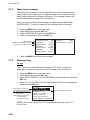
Receiving messages
How to view a received message
When a message is received, the window shown
right appears on the display. To view the contents of
the message follow the procedure below.
1-26
MESSAGE !
PRESS ANY KEY
1. OPERATION
1.
2.
3.
4.
Press any key to erase the message.
Press the MENU key to show the main menu.
Select MSG then press the ENT key.
Select RX LOG then press the ENT key.
Date and time
message received
("NEW" displayed for
unread message)
[RX LOG]
03/MAY 13:25 NEW
[UTC] FROM: 4310199111
28/MAR 03:43
[UTC] FROM: 431099111
22/MAR 18:00
[UTC] FROM: 431099111
MMSI of sender
1/3[T ] MSG[ENT] QUIT[MENU]
5. To view the contents of a message, select
the message then press the ENT key.
The figure shown right is an example of a
received message.
[RX ADDRESSED MSG]*
I HAVE CHANGED MY
COURSE TO 350 DEGREE.
QUIT[MENU]
*RX BROADCAST MSG for
received broadcast message
6. Press the DISP key to close the log.
Automatically displaying incoming messages
You can display incoming messages automatically as follows:
1. Press the MENU key to open the menu.
2. Select USER SETTINGS then press the ENT key.
[USER SETTINGS]
KEY BEEP
: ON
ALARM BUZZER : ON
AUTO SORT
: ON
DISP SART TEST : ON
LONG RANGE
RECEIVED MSG
CPA/TCPA ALARM
NOTE: For INLAND AIS mode, the
USER SETTINGS menu has two
pages. See section 2.9 to 2.11.
3. Select RECEIVED MSG, then press the
ENT key.
[RECEIVED MSG]
POPUP
: ALL
BUZZER
: ON
4. Select POPUP, then press the ENT key
1-27
1. OPERATION
5. Select which category of receive message to display automatically then
press the ENT key.
ALL: Display any message upon receipt.
ABM: Display only addressed binary messages, upon their receipt.
OFF: Disable automatic displaying of incoming messages.
ALL
ABM
OFF
6. To get an audio alert when the message type selected at step 5 is received,
set "BUZZER" to ON.
7. Press the DISP key to close the menu.
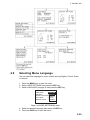
1.8.3
TX and RX message logs
The FA-150 stores the latest 20 each of transmitted and received messages in
respective message logs. When a log becomes full, the oldest message in the
log is automatically deleted to make room for the latest.
When you receive a message, a popup shows MESSAGE! To display a
message log, do the following:
1. Press the MENU key to open the menu.
2. Select MSG then press the ENT key.
3. Select TX LOG or RX LOG as appropriate then press the ENT key. Below
is an example of the TX log. For the appearance of the RX log, see section
1.8.2.
Date and time message
transmitted, message status
OK: Message transmitted
successfully
FAIL: Message could not
be transmitted
- - - -: Waiting for results
[TX LOG]
31/APR 13:25 OK
[UTC] TO: 431099111
27/MAR 03:43 OK
[UTC] TO: 431099111
19/MAR 18:00 OK
[UTC] TO: 431099111
Time transmitted, addressee
1/20[ ] MSG[ENT] QUIT[MENU]
4. To view the contents of a message, select it with ▼ or ▲ then press the
ENT key. Below is an example of a transmitted message. For an example
of a received message, see section 1.8.2.
[TX ADDRESSED MSG]*
CHANGE YOUR COURSE TO
350 DEGREE.
QUIT[MENU]
*TX BROADCAST MSG for
transmitted broadcast message
5. Press the DISP key to close the log.
1-28
1. OPERATION
1.9
Regional Operating Channels
AIS operates primarily on two dedicated VHF channels, CH 2087 and CH2088.
Where these channels are not available regionally, the AIS is capable of being
automatically switched to designated alternate channels by means of a
message from a shore facility. Where no shore based AIS or GMDSS sea area
A1 station is in place, the AIS should be switched manually as in section 1.9.2.
A regional operating area is set with the procedure shown below. The most
recent eight areas are memorized.
• Automatic setting of VHF DSC (channel 70) from shore-based AIS
• Automatic setting by AIS message from shore-based AIS
• Setting by shipboard system such as ECDIS
• Manual setting
The default area is as follows:
• Tx power: 12.5 W
• Channel no. 2087, 2088
• Frequency bandwidth: 25 kHz
• Tx/Rx mode: Tx/Rx
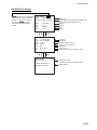
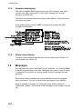
1.9.1
Viewing channels, Tx power
Do the following to view current channels.
1. Press the MENU key to open the menu.
2. Select CHANNEL SETTINGS then press the
ENT key.
[CHANNEL SETTINGS]
VIEW CHANNEL
EDIT CHANNEL
QUIT[MENU]
3. Select VIEW CHANNEL then press the ENT key.
Power
Channel
[VIEW CHANNEL]
POWER : 12.5W
CHANNEL NO.
CH-A: 2087
CH-B: 2088
QUIT[MENU]
4. Press the DISP key to close the display.
1-29
1. OPERATION
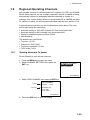
1.9.2
Displaying, editing regional operating area status
You may display the status of regional operating areas currently memorized in
the equipment. Nine of any combination of AIS message from shore-based AIS,
DSC message, manual settings and commands from ECDIS or a PC may be
registered and one will be HIGH SEA.
About registering areas
• AIS and DSC messages registered within last two hours cannot be edited.
• An item labeled HIGH SEA cannot be registered. (“HIGH SEA” are data used
for international waters not controlled by shore-based AIS.)
• If two areas overlap one another the older data is deleted.
• Data older than five weeks is deleted.
• Area data is deleted when it is more than 500 miles from the area for which it
was registered.
1. Press the MENU key to open the menu.
2. Select CHANNEL SETTINGS then press the ENT key.
3. Select EDIT CHANNEL then press the ENT
[EDIT CHANNEL]
key.
SELECT NO.: File number, 0-9. In order of
distance from own ship,
from closest to furthest.
SELECT NO. : 0
TIME [UTC]
- -/- - - - -: - -: - FROM
MMSI: - - - - - - - - TYPE: MANUAL
QUIT [MENU] EDIT[ENT]
TIME:
Data and time equipment
controlled by external source.
MMSI:
MMSI displayed for control by DSC or shore-based AIS.
Dashes or “EMPTY” (no data) otherwise.
TYPE:
How channel is controlled: AIS, AIS message; HIGH SEA
(for reference setting), PI, ECDIS or PC; DSC, DSC;
MANUAL, manual control
Note: MMSI and TYPE must be set to other than “HIGH SEA” to edit.
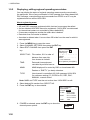
4. Select desired file number from SELECT NO.
5. Press the ENT key to show details.
[EDIT CHANNEL]
1/2
FROM MMSI: _ _ _ _ _ _ _ _ _
POWER : 12.5W
CH NO. CH-A: 2087
CH-B: 2088
MODE
CH-A: TX/RX
CH-B: TX/RX
ZONE:
1NM
6. POWER is selected; press the ENT key to show the
channel power options.
1-30
1W
12.5W
1. OPERATION
7. Select power desired then press the ENT key.
8. CH NO. CH-A is selected; press the ENT key.
9. Select channel number for CH-A then press the ENT key.
10. CH NO. CH-B is selected; press the ENT key.
11. Select channel number for CH-B then press the ENT key.
12. MODE CH-A is selected; press the ENT key.
TX/RX
RX
UNUSED
13. Select desired mode for CH-A then press the ENT key.
Mode
1
2
3
4
5
6
CH-A
TX/RX
TX/RX
RX
RX
RX
UNUSED
CH-B
TX/RX
RX
TX/RX
RX
UNUSED
RX
14. MODE CH-B is selected; press the ENT key.
15. Select desired mode for CH-B then press the ENT key.
16. ZONE is selected; press the ENT key.
17. Key in the zone distance then press the ENT key. (The setting range is 1 to
8 (nm)).
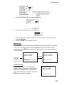
18. Use ▼ or ▲ to show page 2 of the [EDIT
[EDIT CHANNEL]
2/2
CHANNEL] sub-menu.
CH AREA
RIGHT TOP
LAT:
0°00.0'N
LON: 0°00.0'E
LEFT BOTTOM
LAT:
0°00.0'N
LON: 0°00.0'E
Note: The available range is
20-200 nm. If the area contains
overlapping data the older data
will be erased.
20-200 nm
19. LAT of RIGHT TOP is selected; press the ENT key. Enter latitude for the
right-top position (northeast point) of the AIS operating area then press the
ENT key.
20. LON of RIGHT TOP is selected; press the ENT key. Enter longitude for the
right-top position (northeast point) of the AIS operating area then press the
ENT key.
21. LAT of LEFT BOTTOM is selected; press the ENT key. Enter latitude for the
left-bottom position (southwest point) of the AIS operating area then press
the ENT key.
22. LON of LEFT BOTTOM is
20-200 nm
selected; press the ENT key.
RIGHT-TOP
Enter longitude for the
left-bottom position (southeast
point) of the AIS operating area
then press the ENT key.
ZONE
1-8 nm
LEFT-BOTTOM
1-31
1. OPERATION
23. Press the MENU key. The prompt shown right
appears.
SAVE CHANNEL.
ARE YOU SURE?
YES
NO
24. Press ◄ to select YES then press the ENT key.
Note:
If a combination other than that shown in the table at step 13 is
selected, the message “ILLEGAL MODE WAS SELECTED PRESS ANY
KEY.” appears.
25. Press the DISP key to close the menu.
Note: If you enter invalid data, the message “OUT OF RANGE!: OO”
appears. Press any key to escape. Reenter data.
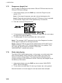
1.10
Enabling/Disabling Alarm Buzzer, Key Beep
You may turn on or off the buzzers that sound for alarms or incoming
messages. Further, you may turn off the beep, which sounds for valid key input.
Note that the alarm buzzer is not related to a radar or ECDIS alarm.
1. Press the MENU key to open the menu.
2. Select USER SETTINGS then press the ENT key.
[USER SETTINGS]
KEY BEEP
: ON
ALARM BUZZER : ON
AUTO SORT
: ON
DISP SART TEST : ON
LONG RANGE
RECEIVED MSG
CPA/TCPA ALARM
NOTE: For INLAND AIS mode, the
USER SETTINGS menu has two
pages. See section 2.9 to 2.11.
3. Select KEY BEEP or ALARM BUZZER as appropriate then press the ENT
key.
4. Select ON or OFF as appropriate then press the ENT key.
5. Press the DISP key to close the menu.
1.11
Long Range
The long range function sets how to reply to a request for own ship data from a
distant station (for example, an Inmarsat C station) and whether to transmit
your ship's position to a satellite via the AIS VHF communication link or not.
1.11.1
LR MODE (Long Range Mode)
The long range mode sets how to reply to a request for own ship data from a
distant station, for example, Inmarsat C station. You may reply automatically or
manually.
1. Press the MENU key to open the menu.
2. Select USER SETTINGS then press the ENT key.
1-32
1. OPERATION
3. Select LONG RANGE then press the ENT key.
4. Select LR MODE then press the ENT key.
5. Select AUTO (auto reply) or MANUAL (manual reply) as appropriate then
press the ENT key.
6. Press the DISP key to close the menu.
Manual reply
For manual reply, the requesting ship's MMSI, name and information requested
(code, see next page) appear. Press the ENT key to send the data, or press
any key other than ENT to send no data. The screen then changes according
to your selection.
[RECEIVED LR]
MMSI: 431456789
NAME: FURUNO
[LR RESPONSE]
MMSI: 431456789
NAME: FURUNO
Press key
Information
requested
(See table
on next page.)
C
RESPONSE?
YES: [ENT] NO: OTHER
C
PRESS ANY KEY
Automatic reply
For automatic reply, the message below
appears when a request for own ship data
arrives from a distant station. Requested
data is automatically transmitted. Press the
ENT key to erase the message.
[LR RESPONSE]
MMSI: 431456789
NAME: FURUNO
C
PRESS ANY KEY
1-33
1. OPERATION
Codes used in long range messages
1.11.2
Code
Meaning
A
Ship name, call sign, IMO number
B
Date message created
C
Position
E
Course over ground
F
Speed over ground
I
Waypoint, ETA
O
Draft
P
Ship type, Load
U
Ship length, width, type
W
Number of crew
MSG27 TX
You can send own ship data to a satellite via the AIS VHF communication link.
1.
2.
3.
4.
Press the MENU key to open the menu.
Select USER SETTINGS then press the ENT key.
Select LONG RANGE then press the ENT key.
Select MSG27 TX then press the ENT key.
[LONG RANGE]
LR MODE
MSG27 TX
: AUTO
: ON
QUIT [MENU]
5. MSG27 TX is selected; press the ENT key.
ON
OFF
6. Select ON or OFF as appropriate then press the ENT key.
ON sends your ship's position to a satellite via the AIS VHF communication
link.
7. Press the DISP key to close the menu.
1-34
1. OPERATION
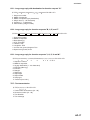
1.12
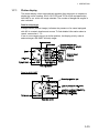
Pilot Plug (Option)
A pilot plug, which is connected between the AIS and a PC, is required to feed
AIS information to a PC. The plug is required for the ships passing through the
Panama Canal and the Saint Lawrence Seaway. The specifications for the pilot
plug are as shown below.
Baudrate:
38400 bps
Note: The following setting is required for the FA-150. If the
pilot does not function, check these settings.
Menu
Setting
[INITIAL SETTINGS][MODE]: [EXT DISPLAY]
[VIEW I/O PORT][VIEW COM PORT][VIEW COM4]
Type:
AMP 206486-1, 206486-2 (9-pin, male)
Signal connection: TX-A ------ Pin 1
TX-B ------ Pin 4
RX-A ------ Pin 5
RX-B ------ Pin 6
SHIELD ------ Pin 9
Connector for AIS
206486-1
Connector for PC
206486-2
206485-1
Examples of connectors
1-35
1. OPERATION
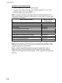
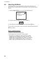
1.13
Viewing Initial Settings
The INITIAL SETTINGS menu, which is locked with a password, is where the
installer enters ship’s MMSI, internal and external antenna positions, ship type
and I/O port settings. You can view the settings on this menu as follows.
1.
2.
3.
4.
1-36
Press the MENU to open the menu.
Select INITIAL SETTINGS then press the ENT key.
Press the ENT key twice.
Select item to view then press the ENT key.
2.
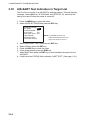
INLAND AIS OPERATION
This section provides the operating procedures for the Inland AIS feature,
which allows use of the AIS transponder on inland waterways or the open sea.
Only those procedures that are different from the Class A AIS transponder are
presented.
Ships with Inland AIS transponders on board autonomously determine their
actual position using the Global Positioning System (GPS), which is part of the
AIS transponder. Furthermore they broadcast their ID and position to other
ships over a distance of 10 to 30 kilometers (depending on the geographical
environment). Other ships in the area receive this information and are able to
display their own position and that of other ships. Inland AIS helps the skipper
in his direct nautical decisions, especially in critical situations, like the approach
of a bend or a constriction.
Further, authorities have the possibility to allow electronic submission of cargo
lists e.g. for transports of dangerous cargo. The standard for “Electronic
Reporting” (ERI) allows the digital, language independent submission of cargo
or passenger reports from ships or agencies to authorities. In combination with
electronic data exchange between the authorities of different countries this
results in less reporting for the skippers. On the other hand all cargo
information is available to authorities in case of an accident.
2.1
Activating the Inland AIS
Enter your key number (received from dealer) to activate the Inland AIS. (If the
key was entered during the installation, entry is not necessary.)
1. Press the MENU key to open the menu.
2. Select DIAGNOSTICS then press the ENT key.
3. Select ACTIVATE KEY then press the ENT key.
[ACTIVATE KEY]
DEVICE ID
XX-XX-XX-XX-XX-XX
KEY
- - -
QUIT[MENU]
4. Press the ENT key, enter your activation key then press the ENT key.
5. Press the MENU key to quit.
If you entered the activation key correctly, the indication "ACTIVATED!"
appears then the system is automatically restarted. Start up with the SOLAS
mode active.
2-1
2. INLAND AIS
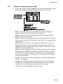
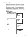
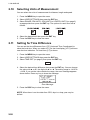
2.2
Selecting AIS Mode
The Inland AIS has two operating modes: Inland (inland waterways) and
SOLAS (SOLAS compliant class A AIS transponder). Select desired mode as
follows:
1. Press the NAV STATUS key to open the NAV STATUS menu.
[NAV STATUS]
NAV STATUS:
01
AIS MODE:
SOLAS
***STATUS DETAIL***
AT ANCHOR
2. Push ▼ to select AIS MODE then press the ENT key.
SOLASRX
INLAND
3. Select SOLAS or INLAND as appropriate then press the ENT key.
You are asked if you are sure to reboot the system. Select YES then press the
ENT key to reboot.
Notes on Inland AIS operation
• IMO NO. is transmitted with all zeroes.
• The draught used in Inland AIS is "Inland draught".
• The number of characters for a text message is as follows
NORMAL MSG with BROAD-CAST: Solas, 156, Inland, 86
NORMAL MSG with ADDRESS-CAST: Solas, 151, Inland, 80
SAFETY MSG with BROAD-CAST: Solas, 161, Inland, 90
SAFETY MSG with ADDRESS-CAST: Solas, 156, Inland, 85
2-2
2. INLAND AIS
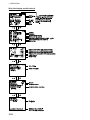
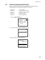
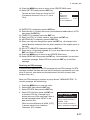
2.3
Entering Voyage-Related Data
Before you embark on a voyage using Inland AIS, set the various voyage
related data (see the list below) on the NAV STATUS menu.
•
•
•
•
•
Destination
Arrival time
Draught
Cargo type
ERI code
•
•
•
•
•
No. of persons
Length and beam of ship
Dynamic information rate
Hazardous cargo
Ship loading status
1. Press the NAV STATUS key.
[NAV STATUS
NAV STATUS:
0
AIS MODE:
INLAND
***STATUS DETAIL***
UNDER WAY USING
ENGINE
2. Press ► to show the DESTINATION sub-menu.
[DESTINATION]
*************(0/0)
[NEW?]
3. NEW is selected; press the ENT key.
[DESTINATION]
ENTER A NEW
DESTINATION
QUIT:[NAV STATUS]
2-3
2. INLAND AIS
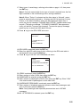
4. Press the ENT key. Enter destination then press the ENT key. You can use
up to 20 alphanumeric characters, and enter 20 destinations. (For how to
enter alphanumeric characters, see “Entering alphanumeric data” on page
1-6.)
Note 1: Each of the characters shown below counts as three characters.
!
$ * ,
\
Note 2: Destinations can be selected, edited and deleted from the
DESTINATION sub-menu. See section 1.5.
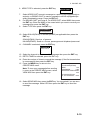
5. Press ► to show the ARRIVAL TIME sub-menu.
[ARRIVAL TIME]
DATE [UTC]:
TIME[UTC]:
- -/- - - -*- -
6.
7.
8.
9.
DATE[UTC] is selected; press the ENT key.
Enter the date of arrival then press the ENT key.
TIME[UTC] is selected; press the ENT key.
Enter the estimated time of arrival then press the ENT key. Use 24-hour
notation.
10. Press ► to show the DRAUGHT sub-menu.
[DRAUGHT]
SOLAS DRAUGHT:
INLAND DRAUGHT:
0.0 m
0.00m
11 SOLAS DRAUGHT is selected; press the ENT key.
12. Enter SOLAS draught (tenths place resolution) then press the ENT key.
13. INLAND DRAUGHT is selected; press the ENT key.
14.Enter inland draught (hundredths place resolution) then press the ENT key.
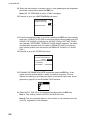
15. Press ► to show the CARGO TYPE sub-menu.
[CARGO TYPE]
TYPE NO.:
00
**** TYPE DETAIL****
NOT AVAILABLE
16. TYPE NO. is selected; press the ENT key.
2-4
2. INLAND AIS
17. Select type of vessel/cargo, referring to the table on page 1-10, then press
the ENT key.
Note 1: Only the second digit for the type of vessel is entered here; the first
digit is entered on the initial settings menu, during installation.
Note 2: When “Tanker” is selected and the Nav status is “Moored”, output
power is automatically switched to 1 W when the SOG is less than 3 knots.
Further, in the above condition, when the SOG becomes higher than 3
knots, the pop-up message “CHANGE NAV STATUS?” appears and a beep
sounds. (The pop-up message “TX POWER CHANGED” also appears to
notify you that the Tx power has changed). To erase the pop-up message,
press any key or lower the SOG below 3 knots.
18. Press ► to go to the ERI CODE sub-menu.
[ERI CODE]
ERI CODE:
8000
****CODE DETAIL****
VESSEL,
TYPE UNKNOWN
19. ERI CODE is selected; press the ENT key.
20. Enter four-digit ERI code (type of ship), referring to the ERI code table in
the Appendix, then press the ENT key.
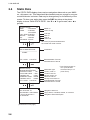
21. Press ► to go to the NO. OF PERSONS sub-menu.
[NO. OF PERSONS]
___
CREW:
_
___
PASSENGER:
SHIPBOARD PERSONNEL
___
NO. OF PERSONS:
0
22. CREW is selected; press the ENT key.
23. Enter number of crew (0-254) then press the ENT key.
24. PASSENGER is selected; press the ENT key.
25. Enter number of passengers (0-8191) then press the ENT key. Enter "8191"
if the total number of passengers is more than 8190.
26. SHIPBOARD PERSONNEL is selected; press the ENT key.
27. Enter number of shipboard personnel (persons other than passengers and
crew, 0-254) then press the ENT key.
Note: Crew, passenger and shipboard personnel are sent in RFM55
messages.
28.NO. OF PERSONS is selected; press the ENT key.
2-5
2. INLAND AIS
29. Enter the total number of persons (sum of crew, passengers and shipboard
personnel) onboard then press the ENT key.
Note: NO. OF PERSONS is sent in IFM16 messages.
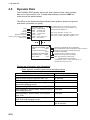
30. Press ► to go to the LENGTH&BEAM sub-menu.
[LENGTH&BEAM]
LENGTH OF SHIP
BEAM OF SHIP:
0.0 m
0.0 m
31. Enter the length and beam of your ship, pressing the ENT key after entering
each item. (If LENGTH OF SHIP is more than three meters greater than the
LENGTH OF CONVOY (A+B total for INT ANT POSN or EXT ANT POSN),
the message "DIFFERENT FROM ANT POSN VALUE" appears. The same
message also appears when the value for BEAM OF SHIP is more than
three meters greater than the total for the BEAM OF CONVOY (C+D ANT
POS.)
32. Press ► to go to the OTHER sub-menu.
[OTHER]
DYNAMIC INFORMATION
RATE: AUTO
HAZARDOUS CARGO:
UNKNOWN
UN/LOADED: UNKNOWN
33. DYNAMIC INFORMATION RATE is selected; press the ENT key. If the
report rate from a base station is used, this setting is ignored. For that
reason, this setting is not always the same as the actual report rate, which
appears on page 2/2 of the DYNAMIC DATA screens.
34. Select AUTO, 10S, 5S or 2S as appropriate then press the ENT key.
Note 1: This setting is fixed to AUTO in the SOLAS mode.
Note 2: The new rate takes effect in 4-8 minutes. In the meantime the rate
is AUTO, regardless of the indication.
2-6
2. INLAND AIS
35. HAZARDOUS CARGO is selected; press the ENT key.
NUMBER OF CONES 0
NUMBER OF CONES 1
NUMBER OF CONES 2
NUMBER OF CONES 3
B-FLAG
UNKNOWN
36. If your ship is carrying hazardous cargo, "cones" (max. 3) have to be shown
on the mast, in daylight with cones and nighttime with blue lights. The
greater the number of the cones the more hazardous the cargo. Select
"NUMBER OF CONES 0" if your ship is not carrying hazardous cargo.
Select B-FLAG if your ship carries explosives or hazardous cargo that
exceeds the hazard level expressed with cones. Select UNKNOWN if you
are unsure of cargo type.
37. Press the ENT key.
38. UN/LOADED is selected; press the ENT key.
UNKNOWN
LOADED
UNLOADED
39. Select LOADED for vessel loaded with cargo, UNLOADED for vessel with
no cargo, or UNKNOWN if you are unsure of the loading status.
40. Press the ENT key.
41. Press the DISP key to close the menu.
2-7
2. INLAND AIS
2.4
Static Data
The STATIC DATA display shows various navigation data such as your MMSI
no., ship name, etc. This data should be checked once per voyage or once per
month whichever is shorter. Data may be changed only on the authority of the
master. To show your static data, press the DISP key twice at the plotter
display to show “OWN STATIC DATA”. Use ▼ or ► to go forward, ▲ or ◄ to
go back.
[STATIC DATA]
1/9
MMSI
: 123456789
NAME
: FURUNO
VOYAGER
CALL SIGN: ZL6DEF1
IMO NO. : 9241062*
ENI
: 1654321
AIS MODE : SOLAS
MMSI no.
Name of ship
Call sign
IMO no.
ENI no.
AIS mode
* All zeroes (0) are transmitted when
the Inland AIS mode is active.
[STATIC DATA]
2/9
SOLAS DESTINATION:
* * * * * * * * * * * * ** * * * *
MAINZ
Destination
ETA: 15/JUL 11:22 UTC*
Estimated date of arrival,
estimated time of arrival
[STATIC DATA]
3/9
INLAND DESTINATION
COUNTRY CODE : DE
LOCATION CODE : MAI
FAIRWAY NO.
: 03901
TERMINAL CODE : 00FRB
FAIRWAY HECT : 00000
ETA: 15/JUL 11:22 UTC*
[STATIC DATA]
4/9
NAV STATUS: 01
UN/LOADED: UNLOADED
***STATUS DETAIL***
AT ANCHOR
(Continued on next page)
2-8
* Time format shown as
UTC (Coordinated
Universal Time) or LT
(Local Time).
Destination type
Country code no.
Location code no.
Fairway section no.
Terminal code no.
Fairway hectometre no.
Estimated date of arrival,
estimated time of arrival
Navigation status no.
Cargo status, unloaded, loaded, or unknown
Navigation status description
2. INLAND AIS
2-9
2. INLAND AIS
2.5
Dynamic Data
The DYNAMIC DATA display shows your ship’s dynamic data, which includes
date, time, ship’s position, etc. To show these displays, press the DISP key
three times at the plotter display.
The Officer of the Watch should periodically check position, speed over ground
and sensor information for quality.
Date
Time
Latitude
Longitude
Speed over ground
Course over ground, Heading
Rate of turn
[DYNAMIC DATA]
1/2
DATE: 10/APR/2008
TIME: 13:24:55 UTC
LAT : 51°55.0213'N
LON : 4°30.0012'E
SOG: 8.1kn
COG: 118.5° HDG:118°
ROT: R10.3°/min*
* If no ROT device is connected and HDG
sentence is input from a gyrocompass, etc.,
the following is displayed:
Rate of turn less than 10°/min.: 0.0
Rate of turn 10°/min. rightward or higher: R>10
Rate of turn 10°/min. leftward or higher: L>10
[DYNAMIC DATA]
2/2
SENSOR: EXTERNAL GPS
RAIM:
USED
POSITION ACCURACY
HIGH
DYNAMIC INFORMATION
REPORT RATE: 3.3SEC
BLUE SIGN:
YES
Navigator (EXTERNAL GPS, INTERNAL
GPS, EXTERNAL DGPS, INTERNAL DGPS, NO FIX)
Receiver Autonomous Integrity Monitoring
(USED or UNUSED)
Position accuracy (HIGH or LOW)
Report rate for dynamic information
Blue sign presence (YES or NO)
( "---" if BLUE SIGN on the INITIAL
SETTINGS menu is "NOT AVAILABLE", or
the SOLAS mode is in use.)
Update rate of dynamic ship information
Ship’s dynamic conditions and nominal reporting interval
2-10
Ship’s dynamic conditions
Ship at anchor and not moving faster than 3 kn
Ship at anchor and moving faster than 3 kn
Ship operating in SOLAS mode, moving 0-14 kn
Ship operating in SOLAS mode, moving 0-14 kn
speed and changing course
Ship operating in SOLAS mode, moving 14-23 kn
Nominal reporting interval
3 minutes
10 seconds
10 seconds
3 1/3 seconds
Ship operating in SOLAS mode, moving 14-23 kn
and changing course
Ship operating in SOLAS mode, moving faster
than 23 kn
Ship operating in SOLAS mode, moving faster
than 23 kn and changing course
Ship operating in inland waterway mode
2 seconds
6 seconds
2 seconds
2 seconds
Assigned between 2 seconds
and 10 minutes
2. INLAND AIS
2.6
Details Ship Display (Mobile Class A)
See section 1.7.2 for how to show this display.
[SHIP INFO]
1/9
MMSI [A] : 431099806
NAME : FURUNO*
CALL SIGN : ZL6DEF1*1
IMO NO. : 9241062
ENI
: 1654321*1, *2
BLUE SIGN: YES
[SHIP INFO]
2/9
LAT : 51°55.0213'N
LON : 4°30.0012'E
SOG : 17.8kn
COG : 213.5°
HDG : 278° PA: H
R/B : 25.12 NM/351.5°
ROT : 0.1°/min
[SHIP INFO]
3/9
CPA
: 0.12NM
TCPA
: 0'23"
NAV STATUS: 10
***STATUS DETAIL***
RESERVED FOR
WING IN GROUND
(WING)
[SHIP INFO]
4/9
SOLAS DRAUGHT: 10.0m
INLAND DRAUGHT
10.00m
ANT LENGTH A : 75m
ANT LENGTH B : 20m
ANT LENGTH C : 15m
ANT LENGTH D : 15m
[SHIP INFO]
5/9
LEN[SHIP]:
95.0m
BEAM[SHIP]:
30.0m
LEN[CONVOY]:
95m
BEAM[CONVOY]:
30m
HAZARDOUS CARGO
NUMBER OF CONES 1
UN/LOADED: UNLOADED
MMSI no.
Name of
ship
Call sign
IMO no.
ENI no.
Blue sign
presence,
absence
"DNGR" (DANGER) appears
(in reverse video) when a
target's CPA and TCPA
are lower than the CPA/TCPA
setting.
"LOST" appears (in reverse video)
when signal from a target is lost.
Six minutes and 40 seconds after
loss of signal the target's data is erased.
*1 If any of these contain an "@" it is
replaced with a space.
Latitude
Longitude
Speed over ground
Course over ground
Heading, Position Accuracy (H, High, L, Low)
Range and bearing from own ship
Rate of turn
*2 The ENI (European Number of
Identification) is an unique vessel
identification number of barges,
passenger ships and tugboats on
European inland waters.
CPA
TCPA
Navigation status
Navigation status details
SOLAS draught
Inland draught
Antenna position A
Antenna position B
Antenna position C
Antenna position D
Length of ship
Beam of ship
Length of convoy
Beam of convoy
Hazardous cargo status
(number of cones (0-3), blue sign, unknown)
Vessel loading status
(loaded, unloaded, unknown)
(Continued on next page)
2-11
2. INLAND AIS
(Continued from previous page)
[SHIP INFO]
TYPE OF SHIP:
6/9
71
***TYPE DETAIL***
FUTURE USE
CARGO SHIP
CARRYING
DG, HS, OR MP(X)
[SHIP INFO]
ERI CODE:
Type of ship
Type of ship details
7/9
8080
ERI code no.
**CODE DETAIL***
MOTOR FREIGHTER
WITH TANKER
[SHIP INFO]
8/9
SENSOR QUALITY
SPEED:
HIGH
COURSE:
LOW
HEADING:
HIGH
DESTINATION
ROTTERDAM
ETA: 15/JUL 17:21 UTC
[SHIP INFO]
9/9
CREW:
10
PASSENGER:
100
SHIPBOARD PERSONNEL
20
NO. OF PERSONS: 130
Quality of speed data (HIGH, LOW)
Quality of course data (HIGH, LOW)
Quality of heading data (HIGH, LOW)
Destination
Estimated time of Arrival. The
time format is shown as UTC
(Coordinated Universal Time) or
LT (Local Time).
No. of crew
No. of passengers
No. of shipboard personnel
No. of persons in total
Note 1: BLUE SIGN information (contained in message type 1) is displayed
when the FA-150 receives an RFM10* message type 6 (inland ship and voyage
related data) or type 8 (safety-related message). When this happens, "BLUE
SIGN" appears on page 1/9 of the DETAILS SHIP displays. If the target
becomes lost but later is re-detected, the target is treated as a mobile station
class A AIS target until BLUE SIGN information is again received.
* RFM=Regional Function Message
Note 2: A target detected as Inland AIS remains as such once information from
the target is received, regardless of any subsequent AIS mode changes.
2-12
2. INLAND AIS
2.7
Inland AIS Specific Messaging
2.7.1
Text message
1. Press the MENU key to open the menu.
2. Select MSG then press the ENT key.
3. TEXT is selected; press the ENT key.
4. CREATE MSG is selected; press the ENT
key.
5. SET MSG TYPE is selected; press the
ENT key.
[MSG]
TEXT
ETA/RTA
NO. OF PERSONS
EMMA WARNING
WATER LEVEL
[TEXT]
CREATE MSG
TX LOG
RX LOG
[CREATE MSG]
SET MSG TYPEE
SET MSG
SEND MSG
[SET MSG TYPE]
ADRS TYPE: BROAD CAST
MMSI
:--------MSG TYPE: SAFETY
CHANNEL: ALTERNATE
RETRY TIMES: MMS
6. ADRS TYPE line is selected; press the ENT key.
BROAD CAST
ADRS CAST
7. Select ADRS CAST to send a message to a specific AIS-equipped ship, or
BROAD CAST to send a message to all AIS-equipped ships within
broadcasting range of your ship. Press the ENT key. For ADRS CAST,
select MMSI then enter MMSI no.
2-13
2. INLAND AIS
8. Select MSG TYPE then press the ENT key.
SAFETY
NORMAL
9. Select message type: NORMAL (message other than safety) or SAFETY
(important navigational or meteorological warning). Press the ENT key.
10. CHANNEL is selected; press the ENT key.
ALTERNATE
BOTH A & B
A
B
11 Select which channel to transmit your message over then press the ENT
key.
12. RETRY TIMES is selected; press the ENT key. If the ADRS TYPE is
BROAD CAST go to step 13. For ADRS CAST, enter the number of times to
re-transmit a message (0-3) then press the ENT key.
13. Press the MENU key to return to the CREATE MSG sub-menu.
14. Select SET MSG then press the ENT key.
*: Number of characters available with each message type for
Inland AIS is as follows:
NORMAL message with BROAD-CAST : 86 characters
NORMAL message with ADDRESS-CAST : 80 characters
SAFETY message with BROAD-CAST
: 90 characters
SAFETY message with ADDRESS-CAST : 85 characters
[SET MSG]
1( 90)* [DIM]HOLD:CLEAR
Number of characters used/available
SET MSG screen
15.Use the CursorPad to enter your message.
16. Press the MENU key to return to the CREATE MSG sub-menu.
17. Select SEND MSG then press the ENT
SEND MESSAGE.
key. The prompt shown below appears.
ARE YOU SURE?
YES
NO
18. Press ◄ to select YES then press the ENT key to send your message.
Message status is shown as follows:
AIS message status messages and their meanings
Message
NOW SENDING.
SEND MESSAGE COMPLETE.
PRESS ANY KEY.
SEND MESSAGE UNSUCCESSFUL.
PRESS ANY KEY
SEND MESSAGE UNSUCCESSFUL.
MMSI: XXXXXXXXX
PRESS ANY KEY.
NOW WAITING RESPONSE.
PRESS ANY KEY.
2-14
Meaning
Message is being sent.
Transmission of message completed. (MMSI is additionally shown in
case of addressed message.)
Message could not be sent.
Message sent successfully, however there is no reply from receiver of
message.
You tried to send a message while the transponder is awaiting receive
confirmation (successful or unsuccessful) for the first-sent message.
After confirmation is received, the next sequential message will be
sent.
2. INLAND AIS
2.7.2
ETA and RTA messages
The purpose of an ETA message is to apply for a time slot at a lock, bridge or
terminal. (Hereafter "lock" refers to lock, bridge or terminal.) The message
contains your ship's ETA at the lock, air draught, the number of assisting
tugboats required and the particulars of the lock (country code, location code,
etc.).
Upon receipt of your ETA message, the lock authority responds with an RTA
(Requested Time of Arrival) message, usually within 15 minutes of receipt of
the ETA message. The RTA message contains lock operational status,
requested time of arrival and the particulars of the lock (country code, location
code, etc.).
Sending an ETA message
1. Press the MENU key to open the menu.
2. Select MSG then press the ENT key.
3. Select ETA/RTA then press the ENT
key.
4. CREATE MSG is selected; press the
ENT key.
5. SET MSG TYPE is selected; press
the ENT key.
[MSG]
TEXT
ETA/RTA
NO. OF PERSONS
EMMA WARNING
WATER LEVEL
[ETA/RTA]
CREATE MSG
ETA LOG
RTA LOG
[CREATE MSG]
SET MSG TYPEE
SET DESTINATION
SET ETA
SEND MSG
[SET MSG TYPE]
MMSI
: 000000000
CHANNEL: ALTERNATE
RETRY TIMES: 3
MMS
2-15
2. INLAND AIS
6. MMSI is selected; press the ENT key.
7. Enter the MMSI of the lock/bridge/terminal you want to pass through then
press the ENT key.
8. CHANNEL is selected; press the ENT key.
ALTERNATE
BOTH A & B
A
B
9. Select the channel over which to send the message then press the ENT
key.
10. RETRY TIMES is selected; press the ENT key.
11. Enter the number of times to re-send the message (if the first transmission
is unsuccessful) then press the ENT key. An ETA message can be resent a
maximum of three times.
12. Press the MENU key to return to the CREATE MSG menu.
13. Select SET DESTINATION then press
[SET DESTINATION]
the ENT key.
* * * * * * * * * * * * * (0/0)
[NEW?]
(If you have entered some
destinations, they appear here.)
14. NEW is selected. If your destination is shown on screen, select it, press the
ENT key then go to step 18. To enter a new destination, go to step 15.
15. With NEW selected, press the ENT key.
[SET DESTINATION]
ENTER A NEW DEST
COUNTRY CODE:
LOCATION CODE:
FAIRWAY NO. :
00000
TERMINAL CODE:
FAIRWAY HECT: 00000
QUIT: [MENU]
UN country code, two 6 bit characters
UN location code, three 6 bit characters
Fairway section no., five 6 bit characters
Terminal code, five 6 bit characters
Fairway hectometre, five 6 bit characters
16. COUNTRY CODE is selected; press the ENT key. Enter the UN country
code of your destination, referring to ISO 3166, then press the ENT key.
17. Enter location code, fairway no.,
[SET DESTINATION]
terminal code, and fairway
hectometre, referring to the ERI
* * * * * * * * * * * * * (0/1)
(Electronic Reporting International) [NEW?]
NLRTM02552LEUVE00000
Guide Part IV Annex 2 for
examples.
Note: To see the results of an
entry, show the SET
DESTINATION screen.
Fairway Hectometer
Terminal Code
Fairway No.
Location Code
Country Code
2-16
2. INLAND AIS
18. Press the MENU key twice to return to the CREATE MSG menu.
19. Select SET ETA then press the ENT key.
[SET ETA]
The date and time format are shown as UTC
ETA
DATE[UTC]
--/--(Coordinated Universal Time) or LT (Local
TIME[UTC]
--:-Time).
AIR DRAUGHT:
0.00 m
NO. OF TUGBOATS:
-
20. DATE[UTC] is selected; press the ENT key.
21. Enter the day (1-2 digits) and month (three-character abbreviation) of ETA
then press the ENT key.
22. TIME[UTC] is selected; press the ENT key.
23. Enter your ETA, in 24-hour notation, then press the ENT key.
24. AIR DRAUGHT is selected; press the ENT key.
25. Enter your ship's air draught then press the ENT key. (Air draught is the
vertical distance measured from the ship's waterline to the highest point on
the ship.)
26. NO. OF TUGBOATS is selected; press the ENT key.
27. Enter the no. of assisting tugboats (0-6) your ship requires then press the
ENT key. Enter "0" for none.
28. Press the MENU key to return to the CREATE MSG menu.
29. Select SEND MSG then press the ENT key. You are asked if you are sure
to send the message. Select YES then press the ENT key to send the
message.
Receiving an RTA message
A lock authority responds to an ETA message with an RTA message. An RTA
message contains the date and time the lock authority requests that your ship
arrive to the lock, lock status and the particulars of the lock (country code,
location code, etc.)
When an RTA message is received, a popup shows " MESSAGE! RTA". To
view the message, do the following:
1.
2.
3.
4.
Press the MENU key to open the menu.
Select MSG then press the ENT key.
Select ETA/RTA then press the ENT key.
Select RTA LOG then press the ENT key
to show the RTA log. A sample log is
shown at the top of the next page. New or
unread messages show "NEW" on the
date and time line.
When the time difference is 00:00, [UTC]
is shown near the time indication.
Otherwise, [LT] is shown.
[RTA LOG]
31/APR 13:25 NEW
[UTC] FROM: 431099111
27/MAR 03:43
[UTC] FROM: 431099111
19/MAR 18:00
[UTC] FROM: 431099111
1/20[T ] MSG[ENT] QUIT[MENU]
2-17
2. INLAND AIS
5. Select the message then press the ENT key.
Lock Status
- Operational
- Limited Operation*
- Out of Order
- Not Available
Date and time
lock authority
requests your
ship to arrive
to the lock
* Obstructed by technical
conditions, only one lock
chamber available, etc.
[RTA LOG]
1/2
STATUS
LIMITED OPERATION
RTA: 05/JUN
12:32 UTC**
RTA message (page 1)
[RTA LOG]
2/2
COUNTRY CODE:
DE
LOCATION CODE: TRI
FAIRWAY NO.:
01234
TERMINAL CODE: 11111
FAIRWAY HECTOMETRE
01000
Lock
particulars
RTA message (page 2)
**: Time format shown as UTC (Coordinated Universal Time) or LT (Local Time).
6. Press the MENU key to close the message.
2.7.3
No. of persons message
A number of persons message informs authorities or ships how many persons
(passengers, crew, shipboard personnel) you have on board your ship. Send
this message on request or in case of an event.
1. Press the MENU key to open the menu.
2. Select MSG then press the ENT key.
3. Select NO. OF PERSONS then press the
ENT key.
4. CREATE MSG is selected; press the ENT
key.
5. SET MSG TYPE is selected; press the ENT
key.
2-18
[NO. OF PERSONS]
CREATE MSGE
TX LOG
[CREATE MSG]
SET MSG TYPEE
VIEW MSG
SEND MSG
[SET MSG TYPE]
ADRS TYPE: BROAD CAST
MMSI
:--------TYPE: SOLAS (IFM16)
CHANNEL: ALTERNATE
RETRY TIMES: MMS
2. INLAND AIS
6. ADRS TYPE is selected; press the ENT key.
7.
8.
9.
BROAD CAST
ADRS CAST
Select ADRS CAST to send a message to a specific AIS-equipped ship or
authority, or BROAD CAST to send a message to all AIS-equipped ships
within broadcasting range. Press the ENT key.
For BROAD CAST, go to step 9. For ADRS CAST, select MMSI then press
the ENT key. Enter the MMSI of the vessel which you want to receive your
message then press the ENT key.
Select TYPE then press the ENT key.
SOLAS(IFM16)
INLAND(RFM55)
10. Select SOLAS(IFM16) or INLAND(RFM55) as applicable then press the
ENT key.
SOLAS(IFM16): Send no. of persons.
INLAND(RFM55): Send no. of crew, passengers and shipboard personnel.
11. CHANNEL is selected; press the ENT key.
ALTERNATE
BOTH A & B
A
B
12. Select the channel to use to send the message then press the ENT key.
13. RETRY TIMES is selected; press the ENT key.
14. Enter the number of times to re-send the message (if the first transmission
is unsuccessful) then press the ENT key.
15. Press the MENU key to return to the
[VIEW MSG]
CREATE MSG menu.
INLAND MSG(RFM55)
Note: To view your message before sending
it, return to the CREATE MSG screen, select
VIEW MSG then press the ENT key.
CREW:
100
PASSENGER:
1000
SHIPBOARD PERSONNEL
200
SOLAS MSG(IFM16)
NO. OF PERSONS: 1300
16. Select SEND MSG then press the ENT key. You are asked if you are sure
to send the message. Select YES then press the ENT key to send the
message.
2-19
2. INLAND AIS
2.7.4
EMMA warning message
EMMA (European Multiservice Meteorological Awareness) warnings are sent
by base stations to skippers to inform them of special meteorological situations.
EMMA does not provide continuous weather information, but only warnings of
wind, rain, snow and ice, thunderstorm, fog, extreme temperatures (low and
high), flood, fire in the forest. These messages are additional to the Notices to
Skippers warnings.
The information includes the following:
•
•
•
•
•
•
•
•
Start time of validity
End time of validity
Fairway section start and end co-ordinates
Type of weather warning
Minimum value
Maximum value
Classification of warning
Wind direction
When you receive an EMMA warning, a popup displays "MESSAGE! EMMA
WARNING". To see the contents of the message, do the following:
1.
2.
3.
4.
Press the MENU key to open the menu.
Select MSG then press the ENT key.
Select EMMA WARNING then press the ENT key.
Select a message then press the ENT key.
The EMMA warning message has three pages and the 1st page looks
something like the left-hand screen on the next page. To view the other
screens, press ►.
[EMMA WARNING]
1/3
START TIME [UTC]
12/JUN 11:30
END TIME [UTC]
12/JUN 11:35
X
W
Start and end times of validity
of warning
2-20
[EMMA WARNING]
2/3
START
LAT : 51°55.0213'N
LON : 4°30.0012'E
END
LAT : 49°55.0213'N
LON : 2°30.0012'E
Fairway section start and
end co-ordinates of warning
X
W
[EMMA WARNING]
3/3
TYPE: SN
SNOW AND ICE
MIN VALUE:
1 cm/h
MAX VALUE:
4 cm/h
CLASS:
MEDIUM
WIND DIRECTION: NW
Type, minimum and maximum
values, class and wind direction
(See below for description.)
2. INLAND AIS
Item
Description
TYPE
FI:
FO:
FL:
HT:
LT:
RA:
SN:
TH:
WI:
Fire in the Forests
Fog
Flood
High Temperature
Low Temperature
Rain
Snow and Ice
Thunderstorm
Wind
Units of measurement are fixed as follows:
•
•
•
•
km/h (wind)
°C (temperature)
cm/h (snow)
l/m²h (rain)
• m (visibility distance in fog)
MIN, MAX VALUE
The minimum and maximum value of respective item over one hour.
For example, if the minimum and maximum values for snow and ice
are 1 and 4 respectively, this means that 1-4 cm of snow or ice has
fallen in one hour.
The indication range is -254 to +254, or "----" in case where a value
is not reported, for example, fire in the forests and flood.
CLASS
Weather classification: SLIGHT, MEDIUM, STRONG/HEAVY,
"- - - - - - - -" (unknown)
WIND DIRECTION
N, NE, E, SE, S, SW, W, NW
5. Press the MENU key to close the message.
2-21
2. INLAND AIS
2.7.5
Water level message
The water level message is sent by base stations to inform skippers about
actual water levels in their area. It is additional short-term information to the
water levels distributed via Notices to Skippers. The message contains the
country code(location), gauge ID and water level.
When you receive a water level message, a popup displays "MESSAGE!
WATER LEVEL". To see the contents of the message, do the following:
1.
2.
3.
4.
Press the MENU key to open the menu.
Select MSG then press the ENT key.
Select WATER LEVEL then press the ENT key.
Select a message then press the ENT key.
Country code
National unique ID of gauge
Positive or negative value
[WATER LEVEL]
1/2
COUNTRY CODE:
DE
GAUGE ID:
1001
WATER LEVEL: 65.43m
GAUGE ID:
1002
WATER LEVEL: 55.43m
GAUGE ID:
1003
WATER LEVEL: -45.43m
[WATER LEVEL]
2/2
GAUGE ID:
1004
WATER LEVEL: -35.43m
5. Press the MENU key to close the message.
2.7.6
Message logs
TX logs
The TX logs store transmitted text messages, ETA, and no. of persons
messages, in respective logs. To see a TX message, do the following:
1. Press the MENU key to open the menu.
2. Select MSG then press the ENT key.
3. Select TEXT, ETA/RTA or NO. OF PERSONS as appropriate then press the
ENT key.
4. Select TX LOG (for TEXT, NO. OF PERSONS) or ETA LOG as appropriate
then press the ENT key.
Date and time message
transmitted, message status
OK: Message transmitted
successfully
FAIL: Message could not
be transmitted
- - - -: Waiting for results
[TX LOG]
31/APR 13:25 OK
[UTC] TO: 431099111
27/MAR 03:43 OK
[UTC] TO: 431099111
19/MAR 18:00 OK
[UTC] TO: 431099111
1/20[T ] MSG[ENT] QUIT[MENU]
Time transmitted, addressee
.
NOTE: Time format is shown as UTC (Coordinated Universal Time) or LT
(Local Time).
2-22
2. INLAND AIS
5. Select a message then press the ENT key. Below are sample TX log
messages.
[TX ADDRESSED MSG]
CHANGING COURSE TO
357 DEGREES AT
12:35.
[TX BROADCAST MSG]
CHANGING COURSE TO
357 DEGREES AT
12:35.
QUIT[MENU]
QUIT[MENU]
TX addressed message
TX broadcast message
[ETA LOG]
1/2
ETA: 05/JUN 12:32 UTC
COUNTRY CODE:
DE
LOCATION CODE: TRI
FAIRWAY NO.:
01234
TERMINAL CODE: 11111
FAIRWAY HECTOMETRE
01000
[ETA LOG]
2/2
NUMBER OF TUGBOATS: 6
AIR DRAUGHT:
1.23m
ETA message (page 1)
ETA message (page 2)
[TX LOG]
SOLAS(IFM16)
NO. OF PERSONS: 100
[TX LOG]
INLAND(RFM55)
CREW:
100
PASSENGER:
255
SHIPBOARD PERSONNEL
41
SOLAS IFM16 no. of
persons message
INLAND RFM55 no. of
persons message
6. Press the MENU key to close the message.
RX logs
The RX logs store received text messages, RTA, EMMA warning and water
level messages, in respective logs. When you receive one of those messages,
a popup shows "MESSAGE! XXX (XXX=message type)". To see the contents
of the message, do the following:
1. Press the MENU key to open the menu.
2. Select MSG then press the ENT key.
3. Select RX LOG (Text), ETA LOG (ETA), RTA LOG (RTA), EMMA WARNING
or WATER LEVEL as appropriate then press the ENT key. Below is the RX
log for text messages. (The RX log for other message types is similar.)
NEW: New or unread message
Date and time
message received
[RX LOG]
31/APR 13:25 NEW
[UTC] FROM: 431099111
27/MAR 03:43
[UTC] FROM: 431099111
19/MAR 18:00
[UTC] FROM: 431099111
MMSI of sender
1/20[ ] MSG[ENT] QUIT[MENU]
2-23
2. INLAND AIS
4. Select the message to view then press the ENT key. Below are examples of
text and RTA messages. For EMMA warning and water level messages, see
section 2.7.4 and 2.7.5, respectively.
[RX ADDRESSED MSG]
WILL CHANGE COURSE
TO 352 DEGREES AT
13:10 APR 10.
[RX BROADCAST MSG]
STORM WARNING FOR
SAN FRANCISCO AREA.
QUIT[MENU]
QUIT[MENU]
RX addressed message
RX broadcast message
[RTA LOG]
2/2
STATUS
LIMITED OPERATION
RTA: 05/JUN
12:32 UTC
[RTA LOG]
2/2
COUNTRY CODE:
DE
LOCATION CODE: TRI
FAIRWAY NO.:
01234
TERMINAL CODE: 11111
FAIRWAY HECTOMETRE
01000
RTA message (page 1)
RTA message (page 2)
5. Press the MENU key to close the message.
2.8
Viewing Initial Settings
The INITIAL SETTINGS menu, which is locked with a password, is where the
installer enters ship’s MMSI, internal and external antenna positions, ship type,
I/O port settings and blue sign status. You can view the settings on this menu
as follows.
1.
2.
3.
4.
2-24
Press the MENU to open the menu.
Select INITIAL SETTINGS then press the ENT key.
Press the ENT key twice.
Select item to view then press the ENT key.
2. INLAND AIS
2.9
Selecting Menu Language
You can select the language for menu window among English, French, Dutch
or German.
1. Press the MENU key to open the menu.
2. Select USER SETTINGS then press the ENT key.
3. Select LANGUAGE (on page 2) then press the ENT key.
[USER SETTINGS] 2/2
LANGUAGE
: ENGLISH
TIME DIFF
: +00:00
ENGLISH
RANGE CPA UNITS FRENCH
: km
SOG UNITS
: kn
DUTCH
LENGTH UNITS : mGERMAN
Page 2 of [USER SETTEINGS] menu
4. Select the desired language then press the ENT key.
5. Press the DISP key to close the menu.
2-25
2. INLAND AIS
2.10
Selecting Units of Measurement
You can select the units of measurement for distance, length and speed.
1. Press the MENU key to open the menu.
2. Select USER SETTINGS then press the ENT key.
3. Select RANGE CPA UNITS, SOG UNITS or LENGTH UNITS (on page 2)
as appropriate then press the ENT key. The options for each item are as
follows.
4. Select the desired unit then press the ENT key.
5. Press the DISP key to close the menu.
2.11
Setting for Time Difference
You can set the time differences from UTC (Universal Time Coordinated) to
show the local time. When you select UTC for the time display, [UTC] is shown
near the time indication. For local time, [LT] is shown.
1. Press the MENU key to open the menu.
2. Select USER SETTINGS then press the ENT key.
3. Select TIME DIFF (on page 2) then press the ENT key.
+ 00:00
4. Select the desired time difference then press the ENT key. You can change
the value with ▲ or ▼, the digit with ► or ◄. The setting range is -14:00 to
+14:00. If you set the value outside the range, the error message appears
shown below. Press any key to close the message.
Error Message
5. Press the DISP key to close the menu.
NOTE: When there is no time data from GPS, days in a leap year may be
shifted.
2-26
3.
MAINTENANCE,
TROUBLESHOOTING
NOTICE
WARNING
ELECTRICAL SHOCK HAZARD
Do not open the equipment.
Only qualified personnel
should work inside the
equipment.
3.1
Do not apply paint, anti-corrosive sealant
or contact spray to coating or plastic
parts of the equipment.
Those items contain organic solvents that
can damage coating and plastic parts,
especially plastic connectors.
Maintenance
Regular maintenance is necessary to maintain performance. A monthly
maintenance program should be established and should at least include the
items listed in the table below.
Maintenance items
Item
Check point
Connectors
Check that all connectors on the rear panel of the transponder
unit and monitor unit are firmly connected.
Cabling
Check cabling for damage. Replace if damaged.
Ground terminal
Check the ground terminal on the monitor unit and transponder
unit for rust. Clean if necessary.
Ground wire
Check that the ground wire on the monitor unit and
transponder unit is firmly fastened.
Monitor unit,
Transponder unit
Dirt and dust should be removed from units with a soft, dry
cloth. For the LCD, wipe it carefully to prevent scratching,
using tissue paper and an LCD cleaner. To remove dirt or salt
deposits, use an LCD cleaner, wiping slowly with tissue paper
so as to dissolve the dirt or salt. Change paper frequently so
the salt or dirt will not scratch the LCD. Do not use solvents
such as thinner, acetone or benzene for cleaning any unit; they
can remove paint and marks and deform the equipment.
3-1
3. MAINTENANCE, TROUBLESHOOTING
3.2
Replacement of Fuse, Resetting the Breaker
3.2.1
Replacement of fuse
The power cable for the monitor unit contains a 3A fuse which protects the
equipment from overvoltage, reverse polarity and equipment fault. If the power
cannot be turned on, check if the fuse has blown. If the fuse has blown, find the
cause before replacing the fuse. If the fuse blows again after replacement,
contact your dealer for advice.
Part
Fuse
Type
FGBO-A 3A AC125V
Code No.
000-549-063
WARNING
Use the proper fuse.
Use of a wrong fuse can cause fire or
result in damage to the equipment.
3.2.2
Resetting the breaker
If the power cannot be turned on, the BREAKER button on the rear panel of the
transponder unit may have activated. The BREAKER button pops out when
overvoltage, reverse polarity or equipment fault is detected, to protect the
system from damage. If the button pops out, find the reason before pushing it
in to restore normal operation.
BREAKER
10A
Breaker
VHF ANT
GPS ANT
3-2
PC
3. MAINTENANCE, TROUBLESHOOTING
3.3
Troubleshooting
The troubleshooting table below provides common symptoms of trouble and
the means to rectify them. If you cannot restore normal operation, do not
attempt to check inside the equipment. Refer any repair work to a qualified
technician.
Troubleshooting
Symptom
Remedy
Power
Cannot turn on the power.
• Check that the power connector is firmly fastened.
• Check the power supply.
Transmitting, receiving messages
Cannot transmit or
• Check that the VHF antenna cable is firmly
receive.
fastened.
• Check the VHF antenna for damage.
• For TX message, try different TX channel.
(operating sequence: MENU, MSG, CREATE
MSG, SET MSG TYPE, CHANNEL)
Can transmit but message • On the SET MSG TYPE sub-menu, check that
is sent to wrong party.
ADRS TYPE is selected to ADRS-CAST and
MMSI is correct, before sending a message.
(operating sequence: MENU, MSG, CREATE
MSG, SET MSG TYPE, ADRS TYPE and MMSI)
Position data
No position data
• Check the GPS antenna for damage.
• Check the GPS antenna cable and its connectors.
3.4
Diagnostics
The FA-150 provides diagnostic tests to check the monitor unit and
transponder unit for proper operation.
3.4.1
Monitor unit test
The monitor unit test shows program no., and checks the ROM, RAM, LCD and
controls.
1. Press the MENU key to open the main menu.
2. Select DIAGNOSTICS then press the ENT key.
For service technician.
Not accessible by user.
[DIAGNOSTICS]
MONITOR TEST
TRANSPONDER TEST
PWR ON/OFF HISTORY
TX ON/OFF HISTORY
MEMORY CLEAR
ACTIVATE KEY
FOR SERVICE
3-3
3. MAINTENANCE, TROUBLESHOOTING
3. MONITOR TEST is selected; press the ENT key. The test program
automatically proceeds in the sequence shown below.
XX.XX = Program version no.
[MONITOR TEST]
BOOT NO.: 2450020-XX.XX
PROG NO.: 2450021-XX.XX
ROM : OK
CONT :53
SDRAM: OK
DIM
:4
PORT : OK
KEY
:
[MONITOR TEST]
BOOT NO.: 2450020-XX.XX
PROG NO.: 2450021-XX.XX
ROM :
CONT :
SDRAM:
DIM
:
PORT :
KEY
:
PUSH KEY
QUIT[MENU] 3 TIMES
QUIT[MENU] 3 TIMES
(a)
(b)
<LCD CHECK>
ALL ON 2 SEC.
ALL OFF 3 SEC.
(e)
(d)
(c)
a) The first screen in the test shows boot no. and program no. The message
“PUSH KEY” prompts you to test the keys. Press each key (except the
PWR key) and arrows on the CursorPad one by one. The name of the
pressed key or arrow appears next to “KEY” if the control is functioning
normally.
b) The ROM, SDRAM and (I/O)PORT (special test connector required,
otherwise “NG” appears) are checked. The results of the ROM/ SDRAM
check are shown as OK or NG (No Good). If NG appears, try the test
again. If NG still appears, contact your dealer for advice.
The contrast and dimmer settings are automatically changed. Check that
their setting indications are reasonable.
c) The screen announces the start of the LCD check.
d) The screen turns black.
e) The screen turns white.
4. The test is repeated. To escape from the test and return to the
DIAGNOSTICS menu, press the MENU key three times when PUSH KEY
is displayed.
3-4
3. MAINTENANCE, TROUBLESHOOTING
3.4.2
Transponder test
The transponder test consists of two tests: memory test and internal GPS
receiver test.
Memory test
The memory can be checked for proper operation and the program number
displayed as follows:
1.
2.
3.
4.
Press the MENU key to open the main menu.
Select DIAGNOSTICS then press the ENT key.
Select TRANSPONDER TEST then press the ENT key.
Select MEMORY TEST then press the ENT key. The program no. is
displayed and the ROM and RAM are checked. The results of the ROM and
RAM check are shown as OK or NG (No Good). For any NG, contact your
dealer for advice. The version of the Mother Board is also shown.
[MEMORY TEST]
PROGRAM NO.
2450018-xx.xx
MAIN ROM : OK
MAIN RAM : OK
SUB RAM : OK
MOT HW
:x
xx.xx: Program Version No.
x: 0, Non-Inland AIS, other
than 0: Inland AIS
5. Press the MENU key to return to the DIAGNOSTICS sub-menu.
3-5
3. MAINTENANCE, TROUBLESHOOTING
Internal GPS test
The internal GPS receiver can be checked for proper operation as follows:
1.
2.
3.
4.
Press the MENU key to open the main menu.
Select DIAGNOSTICS then press the ENT key.
Select TRANSPONDER TEST then press the ENT key.
Select GPS TEST then press the ENT key to start the test. The program no.
and the test results appear as shown below.
OK: Normal
NG: (No Good). NG appears along with reason for NG:
DATA BACKUP ERR: Data backup problem
GPS COMMUNICATION ERROR: Comm. error with internal GPS
receiver
PARAMETER BACKUP ERR: Parameter backup problem
ROM ERROR
RAM ERROR
ANTENNA ERROR
[GPS TEST]
PROGRAM NO.
485026xxxx
TEST: OK
xxxx: Program Version No.
5. Press the MENU key to return to the DIAGNOSTICS sub-menu..
3-6
3. MAINTENANCE, TROUBLESHOOTING
3.4.3
Power on/off history
The PWR ON/OFF HISTORY log shows the date and time of the latest 30
power-ons and power-offs. If the interval between power-off and power-on is
less than 15 minutes those times are not shown.
1. Press the MENU key to open the main menu.
2. Select DIAGNOSTICS then press the ENT key.
3. Select PWR ON/OFF HISTORY then press the ENT key.
[PWR ON/OFF HISTORY]
PWR-ON
17/MAY/2009
05:35:54
PWR-OFF 17/MAY/2009
04:56:57
PWR-ON
17/MAY/2009
04:06:34
Power turned on 17 May 2009
at 05:35:54
QUIT[MENU]
4. Use ▼ or ► to change page in the forward direction; ▲ or ◄ to change
page in the reverse direction.
5. Press the MENU key to return to the DIAGNOSTICS sub-menu.
3.4.4
Tx on/off history
The TX ON/OFF HISTORY log shows the date and time of the latest 30
transmissions.
1. Press the MENU key to open the main menu.
2. Select DIAGNOSTICS then press the ENT key.
3. Select TX ON/OFF HISTORY then press the ENT key.
[TX ON/OFF HISTORY]
TX-ON
17/MAY/2009
05:35:54
TX-OFF
17/MAY/2009
04:34:57
TX-ON
17/MAY/2009
04:33:57
Tx at 17 May 2009
at 05:35:54
PAGE (1/2) :[ ] QUIT[MENU]
4. Use ▼ or ► to change page in the forward direction; ▲ or ◄ to change
page in the reverse direction.
5. Press the MENU key to return to the DIAGNOSTICS sub-menu.
3-7
3. MAINTENANCE, TROUBLESHOOTING
3.5
Alarm Status
The alarm sounds for equipment error and is accompanied by a flashing popup
indication. Press any key to silence the alarm and erase the popup. To see
which alarm(s) has been violated, display the ALARM STATUS log as shown
below.
1. At the plotter display, press the DISP key four times to show the ALARM
STATUS display.
Alarm name,
date and time
of alarm
[ALARM STATUS]
EPFS 7/MAY
L/L
7/MAY
SOG
7/MAY
COG
6/MAY
HDG
3/MAY
ROT
19/APR
4:32:16
4:02:01
2:34:54
7:09:32
8:00:21
9:05:22
2. Use ▼ or ▲ to scroll the log.
Alarm statuses and their meanings
Alarm Status
Indication
ANT
CH1
CH70
Antenna VSWR trouble. Continued operation possible.
TDMA RX1 Board trouble. TX stopped on corresponding TX
channel.
TDMA RX2 Board trouble. TX stopped on corresponding TX
channel.
DSC RX Board trouble, transmission stopped on CH70.
COG
Invalid COG data
EPFS
No data from external navigator. Continued operation
possible.
General system failure
Invalid/nonexistent HDG data
No L/L data
Minimum input device failure
Invalid ROT data
Invalid SOG data
TX malfunction
CH2
FAIL
HDG
L/L
MKD
ROT
SOG
TX
3-8
Meaning
3. MAINTENANCE, TROUBLESHOOTING
3.6
Error and System Messages
The FA-150 displays the following error and system messages to alert you to
errors and events.
Error and system messages and their meanings
Message
CAN’T DISPLAY INVALID DATA
CAN’T DISPLAY OVER LAT85°
COLLISION ALARM
COMMUNICATION ERROR
DIFFERENT FROM ANT POS
VALUE
ERROR REGIST
GPS COMMUNICATION ERROR
ILLEGAL COMBINATION OF
PRIORITY
ILLEGAL MODE WAS SELECTED.
PRESS ANY KEY.
INCORRECT NUMBER! PRESS
ANY KEY
INPUT THE UTC TIME!
MESSAGE!
MESSAGE! EMMA WARNING
MESSAGE! RTA
MESSAGE! TEXT
MESSAGE! WATER LEVEL
NO CREW
NO ETA, DESTINATION
NO MESSAGE
NO NUMBER OF PERSONS
NO OWN SHIP POSITION
AVAILABLE
NO PASSENGER
NO SEL
NO SHIPBOARD PERSONNEL
OUT OF RANGE! 0-255
Meaning
No position data.
Own ship’s latitude is higher than 85°.
AIS target within set CPA/TCPA range.
No communication with transponder.
For Inland AIS. Total sum of internal and external
antenna distances are more than 3 meters greater than
LENGTH (BEAM) OF SHIP.
1) You entered MSG22 or DSC data whose sea areas
overlap one another, or wrong NAV STATUS
2) You entered NAV STATUS as 14 on page 1 of NAV
STATUS menu.
Communication error with internal GPS, shown at
internal GPS self test.
Duplication in priority setting.
Invalid combination of channels is selected for editing.
Incorrect ERI code entered.
Input the UTC time when there is no time data from
GPS.
Class A AIS text message received.
Inland AIS EMMA warning message received.
Inland AIS RTA message received.
Inland AIS text message received.
Inland AIS water level message received
Number of crew not entered in no. of persons message.
You attempted to send a message that does not have
ETA or destination.
No TX message to send when you attempted to send a
message.
Number of persons not entered in no. of persons
message.
Invalid own ship position.
Number of passengers not entered in no. of persons
message.
Attempted to see detailed data for a target which has no
data.
Number of shipboard personnel not entered in no. of
persons message.
Wrong IP, sub net mask or gateway address.
3-9
3. MAINTENANCE, TROUBLESHOOTING
OUT OF RANGE! 0-65535
OUT OF RANGE! 10-30
OUT OF RANGE! BEAM:0-100
OUT OF RANGE! CH-A(CH-B)
DOESN'T EXIST
OUT OF RANGE! CPA:0-6.00
OUT OF RANGE! CREW:0-254
OUT OF RANGE! DAY
OUT OF RANGE! DRAUGHT:0-20.0
OUT OF RANGE! DRAUGHT:0-25.5
OUT OF RANGE! HOUR:0-23*
OUT OF RANGE!: INVALID
CHANNEL
OUT OF RANGE! LENGTH:0-800
OUT OF RANGE! MINUTE:0-59*
OUT OF RANGE! NAV STATUS:0-15
OUT OF RANGE!
PASSENGER:0-8190
OUT OF RANGE!
PERSONNEL:0-254
OUT OF RANGE! RETRY
TIMES:0-3. PRESS ANY KEY.
OUT OF RANGE! TCPA:0-60
OUT OF RANGE! TUGBOAT:0-6
OUT OF RANGE! TYPE NO.:10-99
OUT OF RANGE! ZONE:1-8
SEND MESSAGE UNSUCCESSFUL
TRANSPONDER WAS REBOOTED
Invalid port number entered.
Invalid NavNet port number entered.
Invalid beam of ship entered.
Invalid channel entered.
Invalid CPA range entered.
Invalid crew no. entered.
Invalid day entered.
Invalid inland draught entered.
Invalid SOLAS draught entered.
Invalid hour entered.
Invalid CH-NO. A or CH-NO. B entered.
Invalid ship's length entered.
Invalid minute entered.
Invalid nav status entered.
Invalid no. of passengers entered.
Invalid no. of personnel entered.
Invalid no. of retry times entered.
Invalid TCPA entered.
Invalid tugboat quantity entered.
Invalid cargo type entered.
Invalid zone entered.
Message could not be sent.
Transponder was rebooted.
* Error message displayed for both even if only one is out of range.
Note: Detection of RX malfunction
1) Detection of TDMA RX malfunction
Frequency error
PLL chip on receiver board generates lock or unlock signal for
synthesizer.
MPU watches and sets status flag which reflects data of ALR sentence.
ID 003 for RX1, ID 004 for RX2
2) Detection of DSC RX malfunction
General error
DSC Error (ID: 005) will happen in case of DSC MPU could not receive
format specifier of the data from DSC amplifier unless RSSI exists more
than 90 seconds.
3-10
3. MAINTENANCE, TROUBLESHOOTING
3.7
GPS Monitor
The GPS monitor display shows information about the built-in GPS receiver,
including position, speed over ground, course over ground, date, time, mode
position accuracy, position-fixing status and RAIM status.
1. Press the MENU key to open the menu.
2. Select INTERNAL GPS then press the ENT key.
Latitude position
Longitude position
Speed over ground, Course over ground
Date
Time
Mode
DGPS
GPS
NO FIX
Position Accuracy
H: High (<10 m, differential mode)
L: Low (>10, autonomous mode)
[INTERNAL GPS]
LAT : 34°44.4639'N
LON : 135°21.2395'E
S/C : 10.9 kn/ 98.9°
UTC : 16/MAY/2009
06:29:02
DGPS
STS: D3D
PA: H RAIM: USED
RAIM Status*
(Receiver Autonomous
Integrity Monitoring)
USED or UNUSED
STS (Position fix Status)
2D: 2D GPS position fix
3D:
D2D:
D3D:
DOP:
3D GPS position fix
2D DGPS position fix
3D DGPS position fix
HDOP > 4 in 2D fix,
or HDOP > 6 in 3D fix
NO FIX: No position fix
*RAIM: Technique whereby the GPS receiver verifies the integrity
of the signals received from the GPS constellation.
3. Press the DISP key to close the display.
3-11
3. MAINTENANCE, TROUBLESHOOTING
3.8
Displaying Sensor Status
The SENSOR STATUS screen shows sensor status.
1. Press the MENU key.
2. Select SENSOR STATUS then press the ENT key.
[SENSOR STATUS]
Sensor status message
UTC CLOCK LOST
QUIT[MENU]
3. Press the DISP key to close the display.
Sensor status messages and their meanings
Sensor Status Message
3-12
Meaning
CH MANAGEMENT
Channel changed (displayed about 30 s)
EXT DGNSS
Using external DGNSS
EXT GNSS
Using external GNSS
EXT SOG/COG
Using external SOG/COG
HDG VALID
Heading data normal
INT DGNSS BEACON
Using internal DGNSS beacon
INT DGNSS MSG 17
MSG 17 corrects internal GNSS with differential
correction
INT GNSS
Using internal GNSS
INT SOG/COG
Using internal SOG/COG
OTHER ROT
Value calculated from HDT, or ROT device used and
talker is other than T1
ROT VALID
ROT data normal
UTC CLOCK LOST
Internal position fix lost
3. MAINTENANCE, TROUBLESHOOTING
3.9
Restoring Default Settings
You may clear all or specific settings to start afresh with default settings. When
all data is cleared, the default settings for all items in the INIT SETTING and
SYSTEM SETTINGS sub-menus are restored. GPS data is also cleared;
however, MMSI and IMO numbers, ship’s name and call sign are not cleared.
1. Press the MENU key to open the menu.
2. Select DIAGNOSTICS then press the ENT key.
3. Select MEMORY CLEAR then press the ENT key.
[MEMORY CLEAR]
MONITOR CLEAR
SET USER DEFAULT
GPS COLD START
QUIT[MENU]
4. Select MONITOR CLEAR, SET USER DEFAULT or GPS COLD START as
appropriate then press the ENT key.
MONITOR CLEAR: Restore default settings for dimmer, contrast
CPA/TCPA, key beep, audio alarm, and received
message alarm.
USER DEFAULT:
Restores all settings to default, except items in the
INITIAL SETTINGS menu (MMSI No., IMO No., ship’s
name and call sign, etc.)
GPS COLD START: Clears GPS Almanac to receive latest Almanac.
MONITOR CLEAR.
SET USER DEFAULT
ARE YOU SURE?
YES
NO
ARE YOU SURE?
YES
NO
MONITOR CLEAR
USER DEFAULT
GPS COLD START.
ARE YOU SURE?
YES
NO
GPS COLD START
5. Press ◄ to select YES then press the ENT key.
For MONITOR CLEAR and USER DEFAULT, a beep sounds then the
equipment restarts.
3-13
3. MAINTENANCE, TROUBLESHOOTING
3.10
AIS-SART Test Indication in Target List
The FA-150 can confirm if an AIS-SART is working properly. This test requires
message 1 data (MMSI No. 97 XXXXXXX, NAV STATUS: 15). Note that this
setting is turned off when the power is turned off.
1. Press the MENU key to open the menu.
2. Select USER SETTINGS then press the ENT key.
[USER SETTINGS]
KEY BEEP
: ON
ALARM BUZZER : ON
AUTO SORT
: ON
DISP SART TEST : ON
LONG RANGE
RECEIVED MSG
CPA/TCPA ALARM
3.
4.
5.
6.
7.
NOTE: For INLAND AIS mode, the
USER SETTINGS menu has two
pages. See section 2.9 to 2.11.
Select DISP SART TEST then press the ENT key.
Select ON then press the ENT key.
Press the DISP key to close the menu.
At the plotter display, press the DISP key.
Select SART then press the ENT key to show detailed information for the
AIS-SART.
8. Confirm that the STATUS field is showing “SART TEST”. (See page 1-19.)
3-14
APPENDIX
Menu Tree - Class A AIS
[MENU] key
MSG
CREATE MSG
TX LOG
RX LOG
SET MSG TYPE
SET MSG
SEND MSG
SENSOR STATUS (Display sensor status.)
INTERNAL GPS (Displays data about internal GPS receiver.)
USER SETTINGS
INITIAL
SETTINGS
KEY BEEP (ON, OFF)
ALARM BUZZER (ON, OFF)
AUTO SORT (ON,OFF)
DISP SART TEST (ON, OFF
LONG RANGE
RECEIVED MSG
CPA/TCPA ALARM
SET MMSI (MMSI, IMO NO., NAME, CALL SIGN)
SET INT ANT POSN
A (0-511 (m))
B (0-511 (m))
C (0-63 (m))
D (0-63 (m))
SET EXT ANT POSN
A (0-511 (m))
B (0-511 (m))
C (0-63 (m))
D (0-63 (m))
SET SHIP TYPE (Type no.)
SET I/O
PORT
SET
COM
PORT
ADRS TYPE
(BROAD CAST, ADRS CAST)
MMSI
MSG TYPE (NORMAL, SAFETY)
CHANNEL
(ALTERNATE, BOTH A & B, A, B)
RETRY TIMES (0-3)
LR MODE (AUTO, MANUAL)
MSG27 TX (ON, OFF)
POPUP (ALL, ABM, OFF)
BUZZER (ON, OFF)
CPA (0.0-6.00 (NM))
TCPA (0-60 (min))
ALARM MODE (ON, OFF)
ALARM BUZZER (ON, OFF)
Note: The INITIAL SETTINGS sub-menu
shown here is the one accessed with a
password, which permits changing of
settings. If accessed without a password,
in which case "SET" in a menu title is
replaced with "VIEW" and settings cannot
be changed.
SET COM1
MODE (LONG RANGE, EXT DISPLAY, DISABLE)
SPEED (IEC61162-1, IEC61162-2)
SET COM2
MODE (EXT DISPLAY, MONITOR, HI LEVEL IF, DISABLE)
SPEED (IEC61162-1, IEC61162-2)
SET COM3 (Same as SET COM2.)
SET COM4
MODE (SENSOR, EXT DISPLAY, DISABLE)
SPEED (IEC61162-1, IEC61162-2)
SET COM5
MODE (SENSOR(Fixed)
SPEED (IEC61162-1, IEC61162-2)
SET COM6
MODE (SENSOR(Fixed)
SPEED (IIEC61162-1, IEC61162-2, AD-10)
MODE (STANDARD, MONITOR, SERVICE, BEACON, DISABLE)
SPEED (4800BPS, 9600BPS, 19.2KBPS, 38.4KBPS, 57.6KBPS)
MODE (STANDARD, MONITOR, SERVICE, DISABLE)
SET LAN
*1
2
PORT*
IP ADDRESS (000.000.000.000 - 255.255.255.255)
*
SUB NET MASK (000.000.000.000 - 255.255.255.255)
* Shown when
PORT NO. (0 - 65535)
optional LAN
IP ADDRESS (000.000.000.000 - 255.255.255.255)
kit is installed.
SUB NET MASK (000.000.000.000 - 255.255.255.255)
NAVNET PORT NO. (10000 - 30000)
GATEWAY ADDRESS (000.000.000.000 - 255.255.255.255)
HOSTNAME (AIS0 - AIS9)
AIS OUTPUT (AUTO, CONTINUOUS)
GPS OUTPUT (AUTO, CONTINUOUS)
*1: For PC Network
ZDA OUTPUT (AUTO, CONTINUOUS)
*2: For NAVNET 3D
SET PRIORITY
SET PC
PORT
SET LR CH
CH-A
CH-B
(Continued on next page)
AP-1
APPENDIX
(Continued from previous page)
CHANNEL
SETTINGS
VIEW CHANNEL (View power and channel settings of channel in use.)
Press [ENT] key to display.
SELECT NO. (0-9)
TIME (UTC)
FROM
MMSI (HIGH SEA, MMSI, EMPTY)
TYPE (HIGH SEA, AIS, PI, DSC,
MANUAL, EMPTY)
EDIT CHANNEL
FROM MMSI
POWER (1W, 12.5W)
CH NO.
CH-A, CH-B
MODE
CH-A, CH-B
ZONE (1-8 (NM)
CH AREA
DIAGNOSTICS
RIGHT TOP
LAT
LON
LEFT BOTTOM
LAT
LON
MONITOR TEST (Displays PROG NO. and BOOT NO.; checks ROM, SDRAM, LCD, controls.)
TRANSPONDER
TEST
MEMORY TEST (Displays PROGRAM NO.;
checks ROM, RAM, and MOT HW.)
GPS TEST (Display PROGRAM NO. and checks internal GPS receiver.)
PWR ON/OFF HISTORY (Log for time of equipment power on and off.)
TX ON/OFF HISTORY (Log for time of equipment transmission on and off.)
MEMORY CLEAR
MONITOR CLEAR (YES, NO)
SET USER DEFAULT (YES, NO)
GPS COLD START (YES, NO)
ACTIVATE KEY (DEVICE ID, KEY[ACTIVATED])
FOR SERVICE (For service technician. Not accessible by user.)
[NAV STATUS]
key
NAV STATUS (00-15)
DESTINATION
ARRIVAL TIME
SELECT
EDIT
DELETE
DATE
TIME
CARGO TYPE (10-99)
DRAUGHT&PERSONS
AP-2
DRAUGHT (0-25.5(m))
NO. OF PERSONS (0-8191)
APPENDIX
Menu Tree - Inland AIS
[MENU] key
MSG
TEXT
ETA/RTA
NO. OF PERSONS
EMMA WARNING
WATER LEVEL
CREATE MSG
TX LOG
RX LOG
CREATE MSG
ETA LOG
RTA LOG
CREATE MSG
TX LOG
SENSOR STATUS (Display sensor status.)
SET MSG TYPE
SET MSG
SEND MSG
SET MSG TYPE
SET DESTINATION
SET ETA
SEND MSG
SET MSG TYPE
VIEW MSG
SEND MSG
INTERNAL GPS (Displays data about internal GPS receiver.)
USER
SETTINGS
INITIAL
SETTINGS
KEY BEEP (ON, OFF)
ALARM BUZZER (ON, OFF)
AUTO SORT (ON,OFF)
DISP SART TEST (ON, OFF
LONG RANGE
LR MODE (AUTO, MANUAL)
MSG27 TX (ON, OFF)
RECEIVED MSG
POPUP (ALL, ABM, OFF)
BUZZER (ON, OFF)
CPA/TCPA ALARM
CPA (0.0-6.00 (NM))
TCPA (0-60 (min))
ALARM MODE (ON, OFF)
ALARM BUZZER (ON, OFF)
LANGUAGE (ENGLISH, FRENCH, DUTCH, GERMAN)
TIME DIFF (-14:00 to +14:00)
RANGE CPA UNITS (NM, km)
SOG UNITS (kn, km/h)
LENGTH UNITS (m, dm)
ADRS TYPE
(BROAD CAST, ADRS CAST)
MMSI
MSG TYPE
(NORMAL, SAFETY)
CHANNEL
(ALTERNATE, BOTH A & B, A, B)
RETRY TIMES (0-3)
COUNTRY CODE, LOCATION CODE,
FAIRWAY NO., TERMINAL CODE,
FAIRWAY HECT
ETA (DATE, TIME), AIR DRAUGHT,
NO. OF TUGBOATS
ADRS TYPE
(BROAD CAST, ADRS CAST)
MMSI
TYPE
(SOLAS(IFM16), INLAND(RFM55))
CHANNEL
(ALTERNATE, BOTH A & B, A, B)
RETRY TIMES (0-3)
SET MMSI (MMSI, IMO NO., NAME, CALL SIGN, ENI)
SET INT ANT POSN
A (0-511 (m))
B (0-511 (m))
C (0-63 (m))
D (0-63 (m))
SET EXT ANT POSN
A (0-511 (m))
B (0-511 (m))
C (0-63 (m))
D (0-63 (m))
Note: The INITIAL SETTINGS sub-menu shown
here is the one accessed with a password,
which permits changing of settings. If
accessed without a password, in which
case "SET" in a menu title is replaced with
"VIEW" and settings cannot be changed.
SET SHIP TYPE (Type no.)
SET I/O
PORT
(Continued on next page)
SET
COM
PORT
SET COM1
MODE (LONG RANGE, EXT DISPLAY, DISABLE)
SPEED (IEC61162-1, IEC61162-2)
SET COM2
MODE (EXT DISPLAY, MONITOR, HI LEVEL IF, DISABLE)
SPEED (IEC61162-1, IEC61162-2)
SET COM3 (Same as SET COM2.)
SET COM4
MODE (SENSOR, EXT DISPLAY, DISABLE)
SPEED (IEC61162-1, IEC61162-2)
SET COM5
MODE (SENSOR(Fixed)
SPEED (IEC61162-1, IEC61162-2)
SET COM6
MODE (SENSOR(Fixed)
SPEED (IIEC61162-1, IEC61162-2, AD-10)
SET PC
PORT
MODE (STANDARD, MONITOR, SERVICE, BEACON, DISABLE)
SPEED (4800BPS, 9600BPS, 19.2KBPS, 38.4KBPS, 57.6KBPS)
AP-3
APPENDIX
(Continued from previous page)
* Shown when
optional LAN kit
is installed.
SET
LAN
PORT*
*2
*1
MODE (STANDARD, MONITOR, SERVICE, DISABLE)
IP ADDRESS (000.000.000.000 - 255.255.255.255; 172.031.024.001)
SUB NET MASK (000.000.000.000 - 255.255.255.255; 255.255.000.000)
PORT NO. (0 - 65535; 10000)
IP ADDRESS (000.000.000.000 - 255.255.255.255; 172.031.024.001)
SUB NET MASK (000.000.000.000 - 255.255.255.255; 255.255.000.000)
NAVNET PORT NO. (10000 - 30000; 10000)
GATEWAY ADDRESS (000.000.000.000 - 255.255.255.255)
HOSTNAME (AIS0 - AIS9)
AIS OUTPUT (AUTO, CONTINUOUS)
*1: For PC Network
GPS OUTPUT (AUTO, CONTINUOUS)
*2: For NAVNET 3D
ZDA OUTPUT (AUTO, CONTINUOUS)
VIEW PRIORITY
VIEW QUALITY
CH-A
SET LR CH
CH-B
SET BLUE SIGN SW (AVAILABLE, NOT AVAILABLE)
CHANNEL
VIEW CHANNEL (View power and channel settings of channel in use.)
SETTINGS
EDIT CHANNEL
SELECT NO. (0-9)
TIME
FROM
Press [ENT] key to display.
FROM MMSI
POWER (1W, 12.5W)
CH NO.
CH-A, CH-B
MODE
CH-A, CH-B
ZONE (1-8 (NM)
CH AREA
RIGHT TOP
MMSI
(HIGH SEA, MMSI, EMPTY)
TYPE
(HIGH SEA, AIS, PI, DSC, MANUAL, EMPTY)
DIAGNOSTICS
LAT
LON
LEFT BOTTOM
MONITOR TEST (Displays program no.; checks ROM, SDRAM, LCD, controls.)
MEMORY TEST (Displays PROG NO.;
TRANSPONDER
LAT
LON
checks ROM, RAM, and MOT HW.)
TEST
GPS TEST (Display PROGRAM NO. and checks internal GPS receiver.)
PWR ON/OFF HISTORY (Log for time of equipment power on and off.)
TX ON/OFF HISTORY (Log for time of equipment transmission on and off.)
MEMORY CLEAR
MONITOR CLEAR (YES, NO)
SET USER DEFAULT (YES, NO)
GPS COLD START (YES, NO)
ACTIVATE KEY [DEVICE ID, KEY[ACTIVATED])
FOR SERVICE (For service technician. Not accessible by user.)
[NAV STATUS]
key
NAV STATUS (00-15)
SELECT
AIS MODE (SOLAS, INLAND)
EDIT
DESTINATION
DELETE
ARRIVAL TIME
DRAUGHT (SOLAS DRAUGHT (0-25.5m), INLAND DRAUGHT (0.01-20.00m))
CARGO TYPE (10-99)
ERI CODE
NO. OF PERSONS (CREW (0-254), PASSENGER (0-8190),
SHIPBOARD PERSONNEL (0-254), NO. OF PERSONS (0-8191))
LENGTH&BEAM (LENGTH (0.0-800.0m) BEAM (0.0-100.0m))
OTHER
AP-4
DYNAMIC INFORMATION RATE (AUTO, 10sec, 5sec, 2sec)
HAZARDOUS CARGO (NUMBER OF CONES 0-3, B-FLAG, UNKNOWN)
UN/LOADED (UNLOADED, LOADED, UNKNOWN)
APPENDIX
Parts List
This equipment contains complex modules in which fault diagnosis and repair down to component
level are not practical (IMO A.694(17)/8.3.1). Only some discrete components are used. FURUNO
Electric Co., Ltd. believes identifying these components is of no value for shipboard maintenance;
therefore, they are not listed in the manual. Major modules can be located on the parts location
photo on page AP-6 and AP-7.
FURUNO
Model
Unit
FA-150
MONITOR UNIT,
TRANSPONDER UNIT
ELECTRICAL PARTS LIST
Blk.No.
TYPE, NAME
LOCATION
PRINTED CIRCUIT BOARD
24P0062, CPU
MONITOR UNIT
24P0034, DSC
TRANSPONDER UNIT
24P0043, GPSTB
TRANSPONDER UNIT
24P0035, MAIN
TRANSPONDER UNIT
24P0036, MOT
TRANSPONDER UNIT
24P0037, PWR
TRANSPONDER UNIT
24P0033A, RX1
TRANSPONDER UNIT
24P0033B, RX2
TRANSPONDER UNIT
24P0032, TX
TRANSPONDER UNIT
GN-8093, GPS RECEIVER
TRANSPONDER UNIT
AP-5
APPENDIX
Parts Location
Monitor unit
CPU Board
24P0062
Monitor unit, rear cover opened
Transponder unit
MOT Board
24P0036
TX Board
24P0032
PWR Board
24P0037
Transponder unit, top cover removed
AP-6
APPENDIX
GPS Receiver
GN-8093
MAIN Board
24P0035
GPSTB Board
24P0043
RX2 Board
24P0033
RX1 Board
24P0033
DSC Board
24P0033
Transponder unit, bottom cover removed
AP-7
APPENDIX
Digital Interface (IEC 61162-1 Edition 4, IEC 61162-2)
Sentence data
Input sentences
ABM, ACA, ACK, AIR, BBM, DTM, GBS, GGA, GLL, GNS, HDT, LRF, LRI, OSD, PIWWIVD,
PIWWSPW, PIWWSSD, PIWWVSD, RMC, ROT, SSD, THS, VBW, VSD, VTG
Output sentences
ABK, ACA, ACS, ALR, LRF, LR1, LR2, LR3, TXT, PIWWSPR, VDM, VDO
Transmission interval
ABK: With each event
ACA, ACS: At RX
ALR: 30 s during alarm, 1 min normally no alarm
LRF, LR1, LR2, LR3: At RX
TXT: Each update
VDM: At RX
VDO: 1 s
Load requirements as listener
Isolation: Provided
Input Impedance: Input Impedance: 110 ohms (130K ohms without jumper plug)
Max. Voltage: ±14 V to GNDiso
Threshold: ±0.2 V (A-B)
Output drive capability
Differential driver output
R=50 ohm 2 v min.
R=27 ohm 1.5 V min.
Driver short-circuit current
60 mA min. 150 mA max.
Data transmission
Data is transmitted in serial asynchronous form in accordance with the standard referenced in 2.1
of IEC 61162-1/2. The first bit is a start bit and is followed by data bits, least-significant-bit as illustrated below.
The following parameters are used:
Baud rate: 38.4 Kbps /4800 bps
Data bits: 8 (D7 = 0), parity none
Stop bits: 1
D0
Start
bit
AP-8
D1
D2
D3
D4
Data bits
D5
D6
D7
Stop
bit
APPENDIX
Serial interface I/O circuit
COM1, 2, 3 port
Baud rate selectable from 4800 and 38400 (bps).
110Ω
COM1_JP
LTC1535C
COM1_JP
RD
COM1_RD_B
COM1_RD_A
TD
COM1_TD_B
COM1_TD_A
GND
GND2
GND
GND_ISO
COM4, 5 port
Baud rate selectable from 4800 and 38400 (bps).
110Ω
COM4_JP
LTC1535C
COM4_JP
COM4_2_RD_B
COM4_2_RD_A
RD_2
COM4_TD_B
COM4_TD_A
TD
GND
GND2
GND
GND_ISO
2.2kΩ
PC400
470Ω
RD_1
COM4_1_RD_H
COM4_1_RD_C
COM6 port
Baud rate selectable from 4800 and 38400 (bps).
110Ω
LTC1535C
COM6_JP
COM6_JP
COM6_2_RD_B
COM6_2_RD_A
COM6_TD_B
COM6_TD_A
2_RD
TD
GND2
GND
GND_ISO
2.2kW
PC400
1_RD/A D_DATA
470Ω
220Ω
COM6_1_RD_H
AD_DATA_H
COM6_1_RD_C/AD_DATA_C
2.2kW
AD_CLK
PC400
220Ω
AD_CLK_H
AD_CLK_C
AP-9
APPENDIX
DISP port
Baud rate selectable from 4800 and 38400 (bps).
LTC1535C
110Ω
RD
DISP_RD_B
DISP_RD_A
TD
DISP_TD_B
DISP_TD_A
GND
GND2
GND
GND_ISO
Blue Sign port
TLP181
5V
270 ohm
RD
Blue Sign_H
Blue Sign_C
Sentence description
Input sentences
ABM - Addressed binary and safety related message
!**ABM, x, x, x, xxxxxxxxx, x, x.x, s--s, x, *hh<CR><LF>
12 3
4
5 6 7 8
1. Total number of sentences needed to transfer the message (1 - 9)
2. Message sentence number (1 - 9)
3. Message sequence identifier (0 - 3)
4. The MMSI of destination AIS unit for the ITU-R M.1371 message (9 digits)
5. AIS channel for broadcast of the radio message (0 - 3)
6. VDL message number (6 or 12), see ITU-R M.1371
7. Encapsulated data (1 - 63 bytes)
8. Number of fill-bits (0 - 5)
ACA - AIS regional channel assignment message
$**ACA,x,IIII.lI, a,yyyyy.yy,a,IIII.II,a,yyyyy.yy,a,x,xxxx,x,xxxx,x,x,x,a,x,hhmmss.ss,*hh<CR><LF>
1 2
3
4
5
6
1. Sequence number, 0 to 9
2. Region Northeast corner latitude - N/S
3. Region Northeast corner longitude - E/W
4. Region Southwest corner latitude - N/S
5. Region Southwest corner longitude - E/W
6. Transition Zone Size
7. Channel A
8. Channel A bandwidth
AP-10
7
8 9 1011121314
15
9. Channel B
10. Channel B bandwidth
11. Tx/Rx mode control
12. Power level control
13. Information source
14. In-use flag
15. Time of “in-use” change
APPENDIX
ACK - Acknowledge alarm
$**ACK,xxx,*hh<CR><LF>
1
1. Local alarm number (identifier) (000 - 999)
AIR - AIS interrogation request
$**AIR,xxxxxxxxx,x.x,x,x.x,x,xxxxxxxxx,x.x,x, a, x.x, x.x, x.x *hh<CR><LF>
1
2 3 4 5
6
7 8 9 10 11 12
1. MMSI of interrogated station 1
2. ITU-R M.1371 message requested from station 1
3. Message sub-section
4. ITU-R M.1371 second message requested from station 1
5. Message sub-section
6. MMSI of interrogated station 2
7. ITU-R M.1371 message requested from station 2
8. Message sub-section
9. Channel used on request
10. No use. Response slot for Message ID 1.1 of Message 15
11. No use. Response slot for Message ID 1.2 of Message 15
12. No use. Response slot for Message ID 2.1 of Message 15
BBM - UAIS broadcast binary message.
$**BBM,x,x,x,x,xx,s--s,x,*hh<CR><LF>
12 3 4 5 6 7
1. Total number of sentences needed to transfer the message (1 - 9)
2. Sentence number (1 - 9)
3. Sequential Message identifier (0 - 9)
4. AIS channel for broadcast of the radio message
5. VDL message no. (8 or 14)
6. Encapsulated data
7. Number of fill-bits, 0 to 5
DTM - Datum reference
$**DTM,ccc,a,x.x,a,x.x,a,x.x,ccc,*hh<CR><LF>
1 2 3 4 5 6 7 8
1. Local datum (W84=WGS84 W72=WGS72 S85=SGS85, P90=PE90
User defined=999, IHO datum code
2. Local datum subdivision code (NULL or one character)
3. Lat offset, min (-59.99999 - 59.59999)
4. N/S
5. Lon offset, min
6. E/W
7. Altitude offset, meters (no use)
8. Reference datum (W84=WGS84 W72=WGS72 S85=SGS85, P90=PE90)
AP-11
APPENDIX
GBS - GNSS satellite fault detection
$**GBS, hhmmss.ss, x.x, x.x, x.x, xx, x.x, x.x, x.x h, h, *hh<CR><LF>
1
2 3 4 5 6 7 8 9 10
1. UTC time of GGA or GNS fix associated with this sentence
2. Expected error in latitude (0.0 - 999.9)
3. Expected error in longitude (0.0 - 999.9)
4. Expected error in altitude (no use)
5. ID number of most likely failed satellite (no use)
6. Probability of missed detection for most likely failed satellite (no use)
7. Estimate of bias in meters on most likely failed satellite (no use)
8. Standard deviation of bias estimate (no use)
9. GNSS system ID
10 GNSS signal ID
GGA - Global positioning system (GPS) fix data
$**GGA, hhmmss.ss, llll.ll, a, yyyyy.yy, a, x, xx, x.x, x.x, M, x.x, M, x.x, xxxx,*hh<CR><LF>
1
2 3
4
5 6 7 8 9 10 11 12 13 14
1. UTC of position (no use)
2. Latitude (0.00000 - 9000.00000)
3. N/S
4. Longitude (0.00000 - 18000.00000)
5. E/W
6. GPS quality indicator
7. Number of satellites in use,00-12, may be different from the number in view (no use)
8. Horizontal dilution of precision (no use)
9. Antenna altitude above/below mean sea level (geoid) (no use)
10. Units of antenna altitude, m (no use)
11. Geoidal separation (no use)
12. Units of geoidal separation, m (no use)
13. Age of differential GPS data (no use)
14. Differential reference station ID, 0000-1023 (no use)
GLL - Geographic position - latitude/longitude
$**GLL,llll.lll,a,yyyyy.yy,a,hhmmss.ss,a,x,*hh<CR><LF>
1 2
3
4
5
6 7
1. Latitude (0.00000 - 9000.00000)
2. N/S
3. Longitude (0.00000 - 18000.00000)
4. E/W
5. UTC of position (no use)
6. Status (A=data valid V=data invalid)
7. Mode indicator (A=Autonomous D=Differential E=Estimated (dead reckoning)
M=Manual input S=Simulator N=Data not valid)
AP-12
APPENDIX
GNS - GNSS fix data
$**GNS,hhmmss.ss,llll.ll,a,IIIII.II,a,c--c,xx,x.x,x.x,x.x,x.x,x.x,a*hh<CR><LF>
1
2 3 4 5 6 7 8 9 10 11 12 13
1. UTC of position (no use)
2. Latitude (0.00000 - 9000.00000)
3. N/S
4. Longitude (0.00000 - 18000.00000)
5. E/W
6. Mode indicator
A=Autonomous D=Differential E=Estimated Mode F=Float RTK M=Manual Input Mode
N=No fix P=Precise R=Real Time Kinematic S=Simulator Mode
7. Total number of satellites in use (00 - 99)
8. HDOP (0.0 - 999.99)
9. Antenna altitude, meters (-999.99 - 9999.99)
10. Geoidal separation (-999.99 - 9999.99)
11. Age of differential data (0 - 999)
12. Differential reference station ID (0000 - 1023)
13. Navigational status indicator (S=Safe C=Caution U=Unsafe V=Navigational status not valid,
equipment is not providing navigational status indication)
HDT - Heading - true
$**HDT, xxx.x,T*hh<CR><LF>
1 2
1. Heading, degrees (0.00 to 360.00)
2. True (T)
LRF - Long-range function
$**LRF,x,xxxxxxxxx,c--c,c--c,c--c*hh<CR><LF>
1
2
3 4 5
1. Sequence number (0 - 9)
2. MMSI of requester
3. Name of requester (1 - 20 characters)
4. Function (1 - 26 characters)
5. Function reply status
LRI - Long-range interrogation
$**LRI,x,a,xxxxxxxxx,xxxxxxxxx,llll.ll,a,yyyyy.yy,a,llll.ll,a,yyyyy.yy,a*hh<CR><LF>
12
3
4
5
6
1. Sequence number (0 to 9)
2. Control flag
3. MMSI of requestor
4. MMSI of destination
5. Latitude - N/S (north-east coordinate)
6. Longitude - E/W (north-east coordinate)
7. Latitude - N/S (south-west coordinate)
8. Longitude - E/W (south-west coordinate)
7
8
AP-13
APPENDIX
OSD - Own ship data
$**OSD, x.x, A, x.x, a, x.x, a, x.x, x.x, a *hh<CR><LF>
1 2 3 4 5 6 7 8 9
1. Heading, degrees true (0.00 - 360.00)
2. Heading status (A=data valid, V=data invalid)
3. Vessel course, degrees true (0.00 - 359.99)
4. Course reference
B=Bottom tracking log
M=Manually entered
W=Water referenced
R=Radar tracking (of fixed target)
P=Positioning system ground reference
5. Vessel speed (0.00 - 999.999)
6. Speed refereence, B/M/W/R/P (See 4.)
7. Vessel set, degrees true, manually entered (0.00 - 360.00)
8. Vessel drift (speed), manually entered (0.00 - 999.999)
9. Speed units (K=km/h N=Knots S=statute miles/h)
RMC - Recommended minimum specific GPS/TRANSIT data
$GPRMC, hhmmss.ss, A, llll.ll, a, yyyyy.yy, a, x.x, x.x, ddmmyy, x.x, a, a, a *hh<CR><LF>
1
2 3 4
5
6 7 8
9
10 11 12 13
1. UTC of position fix (000000 - 235959)
2. Status (A=data valid, V=navigation receiver warning)
3. Latitude (0.0000 - 9000.0000)
4. N/S
5. Longitude (0.0000 - 18000.0000)
6. E/W
7. Speed over ground, knots (0.0 - 9999.9)
8. Course over ground, degrees true (0.0 - 359.0)
9. Date (010100 - 311299)
10. Magnetic variation, degrees E/W (0.0 - 180.0/NULL)
11. E/W
12. Mode indicator
(A= Autonomous D= Differential E=Estimated (dead reckoning) mode
F=Float RTK M=Manual input mode N=No fix P=Precise R=Real time kinematic
S= Simulator mode)
13. Navigational status indication
(S=Safe C=Caution U=Unsafe V=Navigational status not valid, equipment is not providing
navigational status indication
ROT - Rate of turn
$--ROT,x.x,A*hh<CR><LF>
1 2
1. Rate of turn, deg/min, "-"=bow turns to port (-9999.9 - 9999.9)
2. Status: A=data valid, V=data invalid
AP-14
APPENDIX
SSD - UAIS ship static data
$**SSD,c--c,c--c,xxx,xxx,xx,xx,c, aa*hh<CR><LF>
1 2 3 4 5 67 8
1. Ship's call sign (1 - 7 characters)
2. Ship's name (1 - 20 characters)
3. Pos. ref. point distance, "A," from bow (0 - 511 Meters)
4. Pos. ref. point distance, "B," from stern (0 - 511 Meters)
5. Pos. ref. point distance, "C," from port beam (0 - 63 Meters)
6. Pos. ref. point distance, "D," from starboard beam (0 - 63 Meters)
7. DTE indicator flag
8. Source identifier
THS - True heading and status
$--THS, x.x, a *hh<CR><LF>
1 2
1. Heading, degrees true (0.00-360.00)
2. Mode indicator
(A=Autonomous E=Estimated (dead reckoning) M=Manual input S=Simulator mode
V=Data not valid (including standby)
VBW - Dual ground/water speed
$**VBW,x.x,x.x,x,x.x,x.x,x,x.x,x,x.x,x,*hh<CR><LF>
1 2 3 4 5 6 7 8 9 10
1. (No use) Longitudinal water speed, knots (-9999.99 - 9999.99)
2. (No use) Transverse water speed, knots (-9999.99 - 9999.99)
3. (No use) Status: water speed, A=data valid V=data invalid
4. Longitudinal ground speed, knots (-9999.99 - 9999.99)
5. Transverse ground speed, knots (-9999.99 - 9999.99)
6. Status: ground speed, A=data valid V=data invalid
7. (No use) Stern transverse water speed, knots (-9999.99 - 9999.99)
8. (No use) Status: stern water speed, A=data valid V=data invalid
9. (No use) Stern transverse ground speed, knots (-9999.99 - 9999.99)
10. (No use) Status: stern ground speed, A=data valid V=data invalid
VSD - UAIS voyage static data
$--VSD,x.x,x.x,x.x,c--c,hhmmss.ss,xx,xx,x.x,x.x*hh<CR><LF>
1 2 3 4
5
6 7 8 9
1. Type of ship and cargo category (0 - 255)
2. Maximum present static draught (0 to 25.5 Meters)
3. Persons on-board (0 - 8191)
4. Destination (1 - 20 characters)
5. Estimated UTC of arrival at destination
6. Estimated day of arrival at destination (00 to 31(UTC))
7. Estimated month of arrival at destination (00 to 12(UTC))
8. Navigational status (0 - 15)
9. Regional application flags (0 - 15)
AP-15
APPENDIX
VTG - Course over ground and ground speed
$--VTG, x.x, T, x.x, M, x.x, N, x.x, K, a,*hh <CR><LF>
1 2 3 4 5 6 7 8 9
1. Course over ground, degrees (0.0 - 359.9)
2. T=True (fixed)
3. (No use) Course over ground, degrees (0.0 - 359.9)
4. (No use) M=Magnetic (fixed)
5. Speed over ground, knots (0.00-9999.9)
6. N=Knots (fixed)
7. Speed over ground (0.00 - 9999.9)
8. K=km/h (fixed)
9. Mode indicator
(A=Autonomous mode, D=Differential mode, E= Estimated (dead reckoning) mode
M=Manual input mode, P=Precise, S=Simulator mode, N=Data not valid)
Output sentences
ABK - UAIS addressed and binary broadcast acknowledgement
$**ABK,xxxxxxxxx,x,x.x,x,x,*hh<CR><LF>
1
2 3 45
1. MMSI of the addressed AIS unit
2. AIS channel of reception
3. Message ID
4. Message sequence number
5. Type of acknowledgement
ACA - See "ACA - AIS regional channel assignment message" on page AP-10
ACS - Channel management information source
$**ACS,x,xxxxxxxxx,hhmmss.ss,xx,xx,xxxx,*hh<CR><LF>
1
2
3
4 5 6
1. Sequence number (0 - 9)
2. MMSI of originator
3. UTC at receipt of channel management information
4. UTC day (01 - 31)
5. UTC month (01 - 12)
6. UTC year
ALR - Set alarm state
$**ALR,hhmmss.ss,xxx,A,A,c—c,*hh<CR><LF>
1
2 34 5
1. Time of alarm condition change, UTC
2. Unique alarm number (identifier) at alarm source (000 - 999)
3. Alarm condition (A=threshold exceeded, V=not exceeded)
4. Alarm acknowledge state (A=acknowledged, V=not acknowledged)
5. Alarm description text (alphanumeric)
LRF - See "LRF - Long-range function" on page AP-13
AP-16
APPENDIX
LR1 - Long-range reply with destination for function request "A"
$**LR1,x,xxxxxxxxx,xxxxxxxxx,c--c,c--c,xxxxxxxxx*hh<CR><LF>
1
2
3
4 5
6
1. Sequence number
2. MMSI of responder
3. MMSI of requester (reply destination)
4. Ship's name (1 - 20 characters)
5. Call sign (1 - 7 characters)
6. IMO number, (9-digit number)
LR2 - Long-range reply for function requests "B, C, E, and F"
$**LR2,x,xxxxxxxxx,xxxxxx,hhmmss.ss,llll.ll,a,yyyyy.yy,a,x.x,T,x.x,N*hh<CR><LF>
1
2
3
4
1. Sequence number
2. MMSI of responder
3. Date (ddmmyy)
4. UTC of Position
5. Latitude - N/S
6. Longitude - E/W
7. Course over ground, degrees True
8. Speed over ground, Knots
5
6
7
8
LR3 - Long-range reply for function requests "I, O, P, U and W"
$**LR3,x,xxxxxxxxx,c--c,xxxxxx,hhmmss.ss,x.x,cc,x.x,x.x,cc,x.x*hh<CR><LF>
1
2
3
4
5
6 7 8 9 10 11
1. Sequence number
2. MMSI of responder
3. Voyage destination (1 - 20 characters)
4. ETA date (ddmmyy)
5. ETA time
6. Draught
7. Ship/cargo
8. Ship length
9. Ship breadth
10. Ship type
11. Persons (0 to 8191)
TXT - Text transmission
$--TXT,xx,xx,xx,c--c*hh<CR><LF>
12 3 4
1. Total number of sentences (01 - 99)
2. Sentence number (01 - 99)
3. Text identifier
4. Text message
AP-17
APPENDIX
VDM - VHF data-link message
$**VDM,x,x,x,x,s--s,x,*hh<CR><LF>
1234 5 6
1. Total number of sentences needed to transfer the message (1 to 9)
2. Message sentence number (1 to 9)
3. Sequential message identifier (0 to 9, NULL)
4. AIS channel Number
5. Encapsulated ITU-R M.1371 radio message (1 - 63 bytes)
6. Number of fill-bits (0 to 5)
VDO - UAIS VHF data-link own-vessel report
!AIVDO,x,x,x,x,s--s,x,*hh<CR><LF>
1234 5 6
1. Total number of sentences needed to transfer the message (1 to 9)
2. Message sentence number (1 to 9)
3. Sequential message identifier (0 to 9, NULL)
4. AIS channel Number (A or B)
5. Encapsulated ITU-R M.1371 radio message (1 - 63 bytes)
6. Number of fill-bits (0 to 5)
Inland AIS specific sentences
Input sentences
PIWWIVD - Inland waterway voyage data
$PIWWIVD x, x, x, xx.xx, xx.xx, x , xxx, xxxx, xxx, hh<CR><LF>
1 2 3 4
5 6 7
8
9
1. Reporting rate, 0-15 1 to 9
2. No. of blue cones, 0-3, 4=B-Flag, 5=unknown (default)
3. Loaded/unloaded, 1=loaded, 2=unloaded, 0=not available (default)
4. Inland draught, 0.01-20.00(m), 0=unknown (default)
5. Air draught, 0.01-40.00(m), 0=unknown (default)
6. No. of tugboats, 0-6,7=unknown (default)
7. No. of crew members, 0-254, 255=unknown (default)
8. No. of passengers, 0-8190, 8191=unknown (default)
9. No. of shipboard personnel, 0-254, 255=unknown (default)
PIWWSPW - Inland AIS security password
$PIWWSPW a, x, c - - - c, x, hh<CR><LF>
1 2
3
4
1. Mode (E: Password input, C: Password change)
2. Password level (1: Maintenance password, 2: User password
3. Password (At least 6 characters)
4. Valid time (0 and 1-60 (s))
AP-18
APPENDIX
PIWWSSD - Inland waterway static ship data
$PIWWSSD CCCCCCCC, xxxx, xxxx, xxxx, x, x, x, hh<CR><LF>
1
2
3
4 5 6 7
1. ENI no. (00000000-9999 9999)
2. ERI ship type (0-9999)
3. Length of ship (0.0-800.0(m))
4. Beam of ship (0.0-100.0(m))
5. Quality of speed information (1: High, 0: Low)
6. Quality of course information (1: High, 0: Low)
7. Quality of heading information (1: High, 0: Low)
PIWWVSD - Inland waterway voyage data
$PIWWVSD x, x, x, x, xx.xx, xx.xx, x, xxx, xxxx, xxx, hh<CR><LF>
1 2 3 4 5
6 7 8
9 10
1. Reporting rate. 1: SOLAS reporting rate, 2: 2s, 0:not available (default)
2. Blue sign, 1: Not set, 2: Set, 0: Not available (default)
3. Hazardous cargo 0-3, 4=B-Flag, 5=unknown (default)
4. Loaded/unloaded, 1=loaded, 2=unloaded, 0=not available (default)
5. Static draught, 0.01-20.00(m), 0=unknown (default)
6. Air draught, 0.01-40.00(m), 0=unknown (default)
7. No. of tugboats, 0-6,7=unknown (default)
8. No. of crew members, 0-254, 255=unknown (default)
9. No. of passengers, 0-8190, 8191=unknown (default)
10. No. of shipboard personnel, 0-254, 255=unknown (default)
Output sentences
PIWWSPR - Inland AIS security password response
$PIWWSPR a, x, x, x, hh<CR><LF>
1 2 3 4
1. Mode (E: Password input, C: Password change)
2. Password level (1: Maintenance password, 2: User password
3. Valid time (0-60 (s))
4. Status (0: Pass, 1: Fail)
AP-19
APPENDIX
VHF Channel List
International mode
Ch No.
1001
1002
1003
1004
1005
6
1007
1018
1019
1020
1021
1022
1023
1024
1025
1026
1027
1028
1060
1061
1062
1063
1064
1065
1066
67
68
69
70
71
72
73
74
75
76
77
1078
1079
1080
1081
1082
1083
1084
1085
1086
1087
AP-20
Freq.
156.05
156.1
156.15
156.2
156.25
156.3
156.35
156.9
156.95
157
157.05
157.1
157.15
157.2
157.25
157.3
157.35
157.4
156.025
156.075
156.125
156.175
156.225
156.275
156.325
156.375
156.425
156.475
156.525
156.575
156.625
156.675
156.725
156.775
156.825
156.875
156.925
156.975
157.025
157.075
157.125
157.175
157.225
157.275
157.325
157.375
Ch No.
1088
1201
1202
1203
1204
1205
1206
1207
208
209
210
211
212
213
214
215
216
217
1218
1219
1220
1221
1222
1223
1224
1225
1226
1227
1228
1260
1261
1262
1263
1264
1265
1266
267
268
269
270
271
272
273
274
275
276
Freq.
157.425
156.0625
156.1125
156.1625
156.2125
156.2625
156.3125
156.3625
156.4125
156.4625
156.5125
156.5625
156.6125
156.6625
156.7125
156.7625
156.8125
156.8625
156.9125
156.9625
157.0125
157.0625
157.1125
157.1625
157.2125
157.2625
157.3125
157.3625
157.4125
156.0375
156.0875
156.1375
156.1875
156.2375
156.2875
156.3375
156.3875
156.4375
156.4875
156.5375
156.5875
156.6375
156.6875
156.7375
156.7875
156.8375
Ch No.
277
1278
1279
1280
1281
1282
1283
1284
1285
1286
1287
2001
2002
2003
2004
2005
2007
8
9
10
11
12
13
14
15
16
17
2018
2019
2020
2021
2022
2023
2024
2025
2026
2027
2028
2060
2061
2062
2063
2064
2065
2066
2078
Freq.
156.8875
156.9375
156.9875
157.0375
157.0875
1571375
157.1875
157.2375
157.2875
157.3375
157.3875
160.65
160.7
160.75
160.8
160.85
160.95
156.4
156.45
156.5
156.55
156.6
156.65
156.7
156.75
156.8
156.85
161.5
161.55
161.6
161.65
161.7
161.75
161.8
161.85
161.9
161.95
162
160.625
160.675
160.725
160.775
160.825
160.875
160.925
161.525
Ch No.
2079
2080
2081
2082
2083
2084
2085
2086
2087
2088
2201
2202
2203
2204
2205
2206
2207
2218
2219
2220
2221
2222
2223
2224
2225
2226
2227
2228
2260
2261
2262
2263
2264
2265
2266
2278
2279
2280
2281
2282
2283
2284
2285
2286
2287
Freq.
161.575
161.625
161.675
161.725
161.775
161.825
161.875
161.925
161.975
162.025
160.6625
160.7125
160.7625
160.8125
160.8625
160.9125
160.9625
161.5125
161.5625
161.6125
161.6625
161.7125
161.7625
161.8125
161.8625
161.9125
161.9625
162.0125
160.6375
160.6875
160.7375
160.7875
160.8375
160.8875
160.9375
161.5375
161.5875
161.6375
161.6875
161.7375
161.7875
161.8375
161.8875
161.9375
161.9875
APPENDIX
USA mode
Ch No.
1001
Freq.
156.05
1003
156.15
1005
6
1007
1018
1019
1020
1021
1022
1023
1024
1025
1026
1027
1028
156.25
156.3
156.35
156.9
156.95
157
157.05
157.1
157.15
157.2
157.25
157.3
157.35
157.4
1061
156.075
1063
1064
1065
1066
67
68
69
70
71
72
73
74
75
76
77
1078
1079
1080
1081
1082
1083
1084
1085
1086
1087
156.175
156.225
156.275
156.325
156.375
156.425
156.475
156.525
156.575
156.625
156.675
156.725
156.775
156.825
156.875
156.925
156.975
157.025
157.075
157.125
157.175
157.225
157.275
157.325
157.375
Ch No.
1088
1201
1202
1203
1204
1205
1206
1207
208
209
210
211
212
213
214
215
216
217
1218
1219
1220
1221
1222
1223
1224
1225
1226
1227
1228
1260
1261
1262
1263
1264
1265
1266
267
268
269
270
271
272
273
274
275
276
Freq.
157.425
156.0625
156.1125
156.1625
156.2125
156.2625
156.3125
156.3625
156.4125
156.4625
156.5125
156.5625
156.6125
156.6625
156.7125
156.7625
156.8125
156.8625
156.9125
156.9625
157.0125
157.0625
157.1125
157.1625
157.2125
157.2625
157.3125
157.3625
157.4125
156.0375
156.0875
156.1375
156.1875
156.2375
156.2875
156.3375
156.3875
156.4375
156.4875
156.5375
156.5875
156.6375
156.6875
156.7375
156.7875
156.8375
Ch No.
277
1278
1279
1280
1281
1282
1283
1284
1285
1286
1287
2001
2002
2003
2004
2005
2007
8
9
10
11
12
13
14
15
16
17
2018
2019
2020
2021
2022
2023
2024
2025
2026
2027
2028
2060
2061
2062
2063
2064
2065
2066
2078
Freq.
156.8875
156.9375
156.9875
157.0375
157.0875
157.1375
157.1875
157.2375
157.2875
157.3375
157.3875
160.65
160.7
160.75
160.8
160.85
160.95
156.4
156.45
156.5
156.55
156.6
156.65
156.7
156.75
156.8
156.85
161.5
161.55
161.6
161.65
161.7
161.75
161.8
161.85
161.9
161.95
162
160.625
160.675
160.725
160.775
160.825
160.875
160.925
161.525
Ch No.
2079
2080
2081
2082
2083
2084
2085
2086
2087
2088
2201
2202
2203
2204
2205
2206
2207
2218
2219
2220
2221
2222
2223
2224
2225
2226
2227
2228
2260
2261
2262
2263
2264
2265
2266
2278
2279
2280
2281
2282
2283
2284
2285
2286
2287
Freq.
161.575
161.625
161.675
161.725
161.775
161.825
161.875
161.925
161.975
162.025
160.6625
160.7125
160.7625
160.8125
160.8625
160.9125
160.9625
161.5125
161.5625
161.6125
161.6625
161.7125
161.7625
161.8125
161.8625
161.9125
161.9625
162.0125
160.6375
160.6875
160.7375
160.7875
160.8375
160.8875
160.9375
161.5375
161.5875
161.6375
161.6875
161.7375
161.7875
161.8375
161.8875
161.9375
161.9875
1 W power on CH13 and CH67.
AP-21
APPENDIX
ERI Codes
ERI code
Full
code
8000
8010
8020
8021
8022
8023
8030
8040
8050
8060
8070
8080
8090
8100
8110
8120
8130
8140
8150
8160
8161
8162
8163
8170
8180
8210
8220
8230
8240
8250
8260
8270
8280
8290
8310
8320
8330
8340
8350
8360
8370
8380
8390
8400
8410
8420
8430
8440
8441
8442
8443
8444
8450
U
Ship name (EN)
No
V
V
V
V
V
V
V
C
C
C
C
C
C
No
No
C
C
V
V
V
V
V
V
V
C
C
C
C
C
C
C
C
C
C
C
C
C
C
C
C
C
C
V
No
C
V
V
V
V
V
V
V
8460
V
8470
8480
8490
8500
8510
1500
1510
1520
1530
1540
1850
1900
1910
C
V
V
V
C
V
V
V
V
V
V
V
V
VESSEL., TYPE UNKNOWN
MOTOR FREIGHTER
MOTOR TANKER
MOTOR TANKER, LIQUID CARGO, TYPE N
MOTOR TANKER, LIQUID CARGO, TYPE C
MOTOR TANKER, DRY CARGO AS IF LIQUID (E.G.CEMENT)
CONTAINER VESSEL
GAS TANKER
MOTOR FREIGHTER, TUG
MOTOR TANKER, TUG
MOTOR FREIGHTER WITH ONE OR MORE SHIPS ALONGSIDE
MOTOR FREIGHTER WITH TANKER
MOTOR FREIGHTER PUSHING ONE OR MORE FREIGHTERS
MOTOR FREIGHTER PUSHING AT LEAST ONE TANK-SHIP
TUG, FREIGHTER
TUG, TANKER
TUG, FREIGHTER, COUPLED
TUG, FREIGHTER/TANKER, COUPLED
FREIGHTBARGE
TANKBARGE
TANKBARGE, LIQUID CARGO , TYPE N
TANKBARGE, LIQUID CARGO , TYPE C
TANKBARGE, DRY CARGO AS IF LIQUID (E.G.CEMENT)
FREIGHTBARGE WITH CONTAINERS
TANKBARGE, GAS
PUSHTOW, ONE CARGO BARGE
PUSHTOW, TWO CARGO BARGES
PUSHTOW, THREE CARGO BARGES
PUSHTOW, FOUR CARGO BARGES
PUSHTOW, FIVE CARGO BARGES
PUSHTOW, SIX CARGO BARGES
PUSHTOW, SEVEN CARGO BARGES
PUSHTOW, EIGTH CARGO BARGES
PUSHTOW, NINE OR MORE BARGES
PUSHTOW, ONE TANK / GAS BARGE
PUSHTOW, 2 BARGES AT LEAST ONE TANKER/GAS BARGE
PUSHTOW, 3 BARGES AT LEAST ONE TANKER/GAS BARGE
PUSHTOW, 4 BARGES AT LEAST ONE TANKER/GAS BARGE
PUSHTOW, 5 BARGES AT LEAST ONE TANKER/GAS BARGE
PUSHTOW, 6 BARGES AT LEAST ONE TANKER/GAS BARGE
PUSHTOW, 7 BARGES AT LEAST ONE TANKER/GAS BARGE
PUSHTOW, 8 BARGES AT LEAST ONE TANKER/GAS BARGE
PUSHTOW䇮9 OR MORE BARGES AT LEAST ONE TANKER/GAS BARGE
TUG, SINGLE
TUG, ONE OR MORE TOWS
TUG, ASSISTING A VESSEL OR LINKED COMBINATION
PUSHBOAT, SINGLE
PASSENGER SHIP, FERRY, CRUISE SHIP, RED CROSS SHIP
FERRY
RED CROSS SHIP
CRUISE SHIP
PASSENGER SHIP WITHOUT ACCOMODATION
SERVICE VESSEL, POLICE PATROL, PORT SERVICE
VESSEL, WORK MAINTAINANCE CRAFT, FLOATING DERRICK, CABLE
SHIP, BUOY SHIP, DREDGE
OBJECT, TOWED, NOT OTHERWISE SPECIFIED
FISHING BOAT
BUNKERSHIP
BARGE, TANKER, CHEMICAL
OBJECT, NOT OTHERWISE SPECIFIED
GENERAL CARGO VESSEL MARITIME
UNIT CARRIER MARITIME
BULK CARRIER MARITIME
TANKER
LIQUIFIED GAS TANKER
PLEASURE CRAFT, LONGER THAN 20 METRES
FAST SHIP
HYDROFOIL
AP-22
AIS code
First
Second
digit
digit
99
79
89
80
80
89
79
80
79
89
79
89
79
89
79
89
31
31
99
99
90
90
99
89
90
79
79
79
79
79
79
79
79
79
80
80
80
80
80
80
80
80
80
52
31
31
99
69
69
58
69
69
99
33
99
30
99
80
99
79
79
79
80
80
37
49
49
APPENDIX
Terminology, Units, Symbols
Terminology
Abbreviation
2D
3D
ABM
ADRS
Two Dimensional Positioning
Three Dimensional Positioning
Addressed Binary Message
Address
Abbreviation
DTL
E
E. G
EMMA
AIS
Automatic Identification System
ENI
ALARM
ALT
ANT
APR
AtoN
AUG
AUTO
AVAIL
BRG
CH
CHG
CLR
CNCL
COG
CONT
CPA
CPU
Alarm
Altitude
Antenna
April
Aids to Navigation
August
Automatic
Available
Bearing
Channel
Change
Clear
Cancel
Course Over the Ground
Contrast
Closest Point of Approach
Central Processing Unit
ENT
EPFS
ERI
ERR
ETA
EXT
FEB
FIX
FULL
GND
GNSS
GPS
H
HDG
HECT
HI
HS
CRS
D2D
D3D
DATE
DAY
DECR
Course
Differential and 2D
Differential and 3D
Date
Day
Decrease
HW
I/O
ID
IF
IFM
IMO
DEL
DEST
DG
DGNSS
DGPS
DIM
DISP
DNG
DNGR
DOP
DPTH
DSC
Delete
Destination
Dangerous Goods
Differential GNSS
Differential GPS
Dimmer
Display
Danger
Danger
Dilution Of Precision
Depth
Digital Selective Calling
INFO
INT
INTRD
JAN
JUN
L
L/L
LAT
LEN
LOG
LON
LR
Meaning
Meaning
Detail
East
for example
European Multiservice Meteorological Awareness system
Unique European Vessel Identification Number
Enter
Electronic Position Fixing System
Electronic Reporting International
Error
Estimated Time of Arrival
External
February
Fix
Full
Ground
Global Navigation Satellite System
Global Positioning System
High
Heading
Hectometer
High
Harmful Substances (applies to
AIS)
Hardware
Input/Output
Identification
Interface
International Function Message
International Maritime Organization
Information
Internal
Intrude
January
July
Low, left
Latitude/Longitude
Latitude
Length
Log
Longitude
Long Range
AP-23
APPENDIX
Abbreviation
LT
MAR
MAX
MAY
MENU
MIN
MKD
MMSI
MOT
MP
MSG
N
NAV
NO.
NOV
OCT
OFF
ON
PA
PI
Meaning
Local Time
March
Maximum
May
Menu
Minimum
Minimum Keyboard Display
Maritime Mobile Services Identity
number
Mother Board
Maritime Pollutant (applies to AIS)
Message
Abbreviation
ROM
ROT
RTA
RX
S
S/C
SAR
SDRAM
SEL
SEP
SET
North
Navigation
Number
November
October
Off
On
Position Accuracy
Presentation Interface, Position Indicator
Port
Position
Power
Right
SIM
SOG
SOLAS
SPD
STS
STW
SW
SYM
TCPA
RAIN
RAM
Range / Bearing
Receiver Autonomous Integrity
Monitoring
Rain
Random Access Memory
REF
RFM
RNG
Reference
Regional Function Message
Range
TX
UN/
LOADED
UTC
WARNING
WAT
WIG
PORT
POSN
PWR
R
R/B
RAIM
TEST
TGT
TIME
TOW
Meaning
Read Only Memory
Rate Of Turn
Requested Time of Arrival
Receive
South
SOG/COG
Search And Rescue
Synchronous Dynamic RAM
Select
September
Set (i.e., set and drift, or setting a
value)
Simulation
Speed Over the Ground
Safety Of Life At Sea
Speed
Status
Speed Through the Water
Switch
Symbol(s)
Time to CPA
Test
Target
Time
Vessel Engaged in Towing Operations
Transmit
LOADED or UNLOADED
Universal Coordinated Time
Warning
Water
Wing In Ground
Units
Abbreviation
°
°C
cm
cm/h
dm
km
km/h
AP-24
Unit
degree(s)
degree(s)
centimeter
centimeter per hour
decimeter
kilometer
kilometer per hour
Abbreviation
kn
Unit
l/m h
knot(s)
liter per square meter
hour
m
min
NM
s
meter
minute(s)
nautical mile(s)
second(s)
2
APPENDIX
Symbols
Symbol
Meaning
Sleeping AIS targets
Selected AIS targets
AIS-SART (Search and Rescue Transmitter)
Selected AIS-SART
Icons
Icon
Meaning
Base station
SAR(Search and Rescue)
Aid to Navigation
AIS-SART
[/]J[−]J[\]J[|] in turn
Normal Operation
AP-25
APPENDIX
This page is intentionally left blank.
AP-26
FURUNO
FA-150
SPECIFICATIONS OF U-AIS TRANSPONDER
FA-150
1
TRANSPONDER UNIT
1.1
TX/RX frequency
156.025 MHz to 162.025 MHz
1.2
Output power
1W or 12.5 W selectable
1.3
Impedance
50 ohms
1.4
DSC receiver
CH70 fixed, 156.525 MHz, G2B, 1200 bps
1.5
Bandwidth
25 kHz/ 12.5 kHz
2
MONITOR UNIT
2.1
Display
4.5-inch, monochrome LCD
2.2
Display size
60 (H) x 95 (W) mm, 120 x 64 dots
3
GPS RECEIVER
3.1
Receiving frequency
1575.42 MHz
3.2
Tracking code
C/A code
3.3
Number of channel
12 channels parallel, 12 satellites
3.4
Position fixing method
All in view, 8-state Kalman filter
3.5
Accuracy
GPS
10 m approx, 95% of the time, (HDOP ≤ 4)
DGPS
5 m approx, 95% of the time
3.6
Tracking velocity
900 kt
3.7
Position-fixing time
Warm start: 36 s, Cold start: 43 s
3.8
Position update interval
1 second typical
3.9
DGPS data receiving
RTCM SC-104 ver-2.1
4
INTERFACE
4.1
Navigation I/O
4 ports, IEC 61162-1 Ed.4 (Nov-10) or 61162-2 (Sep-98)
Input
VSD, SSD, ABM, BBM, ACA, ACK, AIR, DTM, GBS, GGA, GLL,
GNS, HDT, LRF, LRI, OSD, RMC, ROT, THS, VBW, VTG
4.2
Output
VDM, VDO, ABK, ACA, ALR, TXT, LR1, LR2, LR3, LRF, LRI
Sensor input
IEC 61162-1 Ed.4 (Nov-10): 3 ports and 61162-2(Sep-98): 3 ports
DTM, GBS, GGA, GLL, GNS, HDT, OSD, RMC, ROT, THS, VBW,
VTG
4.3
External beacon or PC
RS-232C
4.4
Heading sensor
AD-10 format
4.5
Alarm output
Contact closure
4.6
Bluesign input
Contact closure
SP-1
E4431S01K
111024
FURUNO
FA-150
5
POWER SUPPLY
5.1
Transponder unit
12-24 VDC: 7-3.5 A
5.2
Monitor unit
12-24 VDC: 0.3-0.15 A
5.3
AC/DC power supply unit (PR-240, option)
100-115/200-230 VAC, 1 phase, 50/60 Hz
6
ENVIRONMENTAL CONDITION
6.1
Ambient temperature
GPS/VHF antenna
-25°C to +55°C (storage: -25°C to +70°C)
Other units
-15°C to +55°C
6.2
Relative humidity
95% at 40°C
6.3
Degree of protection
GPS/VHF antenna
IPX6
Transponder unit
IP20
Monitor unit
IP22
6.4
Vibration
IEC 60945 ed.4
7
COATING COLOR
7.1
GPS antenna
N9.5
7.2
Transponder unit
N3.0
7.3
Monitor unit
Panel: N3.0, Chassis: 2.5GY5/1.5
SP-2
E4431S01K
111024
INDEX
A
AIS-SART test indication .............................. 3-14
Alarm status.................................................... 3-8
Alarm status display ..................................... 1-24
B
Breaker reset .................................................. 3-2
Buzzer..................................................1-32, 2-26
C
Channels
setting ....................................................... 1-30
viewing...................................................... 1-29
Contrast .......................................................... 1-4
Controls .......................................................... 1-1
CPA/TCPA .................................................... 1-11
D
Dangerous (target) list .................................. 1-22
Default settings............................................. 3-13
Details display
mobile class A (inland AIS) ....................... 2-11
Diagnostics
GPS test (transponder) .............................. 3-6
memory test (transponder) ......................... 3-5
monitor unit test.......................................... 3-3
power on/off history .................................... 3-7
TX on/off history ......................................... 3-7
DIM key........................................................... 1-4
Dimmer ........................................................... 1-4
DISP key....................................................... 1-12
Dynamic data
class A ...................................................... 1-24
inland AIS ................................................. 2-10
E
EMMA warning message (inland AIS) .......... 2-20
Error messages .............................................. 3-9
ETA message (inland AIS)............................ 2-15
F
Fuse replacement........................................... 3-2
G
GPS monitor ................................................. 3-11
GPS test (transponder)................................... 3-6
I
Info display
AIS-SART ................................................. 1-19
AtoN.......................................................... 1-20
base station .............................................. 1-18
mobile class A (class A AIS) ..................... 1-16
mobile class B .......................................... 1-17
SAR .......................................................... 1-18
Initial settings
class A...................................................... 1-36
Inland AIS........................................ 2-24, 2-25
Inland AIS
activating .................................................... 2-1
details display........................................... 2-11
dynamic data............................................ 2-10
EMMA warning message ......................... 2-20
ETA message ........................................... 2-15
mode .......................................................... 2-2
no. of persons message........................... 2-18
RTA message ........................................... 2-17
RX logs..................................................... 2-23
static data ................................................... 2-8
text message............................................ 2-13
TX logs ..................................................... 2-22
voyage related data.................................... 2-3
water level message ................................ 2-22
K
Key beep ............................................. 1-32, 2-26
L
Long range mode ......................................... 1-32
M
Maintenance................................................... 3-1
Memory clear................................................ 3-13
Memory test (transponder)............................. 3-5
MENU key ...................................................... 1-5
Messages
EMMA warning (inland AIS) ..................... 2-20
ETA (inland AIS) ....................................... 2-15
no. of persons (inland AIS)....................... 2-18
receive message pop-up window............. 1-27
receiving (inland AIS) ............................... 2-24
RTA (Inland AIS)....................................... 2-17
text, class A .............................................. 1-24
text, inland AIS ......................................... 2-13
water level (inland AIS) ............................ 2-22
Monitor unit test.............................................. 3-3
N
NAV STATUS key .................................... 1-7, 2-3
No. of persons message (inland AIS)........... 2-18
P
Plotter display............................................... 1-13
Power on/off ................................................... 1-2
Power on/off history........................................ 3-7
Program number record ................................... vii
IN-1
INDEX
PWR key.........................................................1-2
R
RTA message (Inland AIS)............................2-17
RX logs
class A ......................................................1-28
inland AIS .................................................2-23
S
Sensor status................................................3-12
Static data
class A AIS................................................1-22
Inland AIS ...................................................2-8
System configuration ........................................ vi
System messages ..........................................3-9
System overview..............................................viii
T
Target list ......................................................1-15
IN-2
Text message
class A ...................................................... 1-24
inland AIS ................................................. 2-13
Transponder test ............................................ 3-5
Troubleshooting.............................................. 3-3
TX logs
class A ...................................................... 1-28
inland AIS ................................................. 2-22
TX on/off history ............................................. 3-7
V
Voyage-related data
class A ........................................................ 1-7
Inland AIS ................................................... 2-3
W
Water level message (Inland AIS) ................ 2-22