1
APPLICATION NOTE
Renesas USB MCU
USB Basic Mini Firmware
R01AN0326EJ0213
Rev. 2.13
Mar 16, 2015
This document is an application note describing the USB Basic Mini Firmware, a sample program for USB interface
control using the Renesas USB MCU.
Target Device
R8C/3MU, R8C/34U, R8C/3MK, R8C/34K, RL78/G1C, RL78/L1C
This program can be used with other microcontrollers that have the same USB module as the above target devices. When
using this code in an end product or other application, its operation must be tested and evaluated thoroughly.
Contents
1.
Overview .............................................................................................................................................................. 2
2.
Registering a Class Driver ...................................................................................................................................... 4
3.
USB-BASIC-F/W Description .................................................................................................................................. 5
4.
Software Configuration ......................................................................................................................................... 7
5.
Peripheral Sample Program (UPL) ....................................................................................................................... 12
6.
Peripheral Controller Driver (PCD) ...................................................................................................................... 25
7.
Host Sample Program (UPL) ................................................................................................................................ 53
8.
Host Control Driver (HCD) ................................................................................................................................... 66
9.
The System Scheduler ......................................................................................................................................... 94
10.
Restrictions ....................................................................................................................................................106
R01AN0326EJ0213 Rev. 2.13
Mar 16, 2015
Page 1 of 107
Renesas USB MCU
1.
USB Basic Mini Firmware
Overview
This application note describes the USB Basic Mini Firmwareusing a Renesas USB MCU.
This document is intended to be used together with the device’s data sheet, seechapter 1.2.
1.1
Functions and Features
The USB Basic Mini Firmware conforms to the Full Speed and Low Speed of Universal Serial Bus Specification (USB
from now on and description). It and enables communication with a USB vendor host or USB vendor peripheral device.
1.2
1.
2.
Related Documents
Universal Serial Bus Revision 2.0 specification
Battery Charging Specification Revision 1.2
[http://www.usb.org/developers/docs/]
Renesas USB MCU User’s Manual: Hardware
Available from the Renesas Electronics Website
3.
Renesas Electronics Website
[http://renesas.com/]
USB Devices Page
[http://renesas.com/usb/]
1.3
List of Terms
Terms and abbreviations used in this document are listed below.
API
APL
cstd
CS+
CDP
DCP
HBC
Data Transfer
:
:
:
:
:
:
:
:
e2 studio
HCD
HDCD
HEW
HM
hstd
H/W
MGR
PBC
PCD
PDCD
psmpl
PP
pstd
RSK
Scheduler
Scheduler Macro
:
:
:
:
:
:
:
:
:
:
:
:
:
:
:
:
:
Application Program Interface
Application program
Prefix for peripheral & host common function of USB-BASIC-F/W
Renesas integration development environment
Charging Downstream Port
Dedicated Charging Port
Host Battery Charging control
Generic name of Bulk transfer and Interrupt transfer
(When the host mode is selected, the Control transfer is contained.)
Eclipse embedded studio (However not supported current release)
Host control driver of USB-BASIC-F/W
Host device class driver (device driver and USB class driver)
High-performance Embedded Workshop
Hardware Manual
Prefix for host function of USB-BASIC-F/W
Renesas USB device
Sequencer of HCD to manage the state of the peripheral device
Peripheral Battery Charging control
Peripheral control driver of USB-BASIC-F/W
Peripheral device class driver (device driver and USB class driver)
Peripheral Sample (code)
Pre-processed definition
Prefix for peripheral function of USB-BASIC-F/W
Renesas Starter Kit
Used to schedule functions, like a simplified OS.
Used to call a scheduler function
R01AN0326EJ0213 Rev. 2.13
Mar 16, 2015
Page 2 of 107
Renesas USB MCU
SDP
Task
UPL
USB
USB-BASIC-F/W
1.4
:
:
:
:
USB Basic Mini Firmware
Standard Downstream Port
Processing unit
User Programming Layer (Upper layer of USB-BASIC-F/W:HDCD, PDCD, APL or etc)
Universal Serial Bus
USB Basic Mini Firmware
(Peripheral & Host USB basic firmware(USB low level) for Renesas USB MCU)
How to Read This Document
This document is not intended for reading straight through. Use it first to gain acquaintance with the package, then to
look up information on functionality and interfaces as needed for your particular solution.
To get acquainted with the source code, read Chapter 4.3.1 and note which MCU-specific files you need select at
directory "devicename\src\HwResource".
Observe which files belong to the application level.
Chapter 5 and Chapter 6 of this document are only for the peripheral mode. Chapter 7 and Chapter 8 of this document are
only for the host mode. Chapter 5 explains how the default peripheral vendor application works. Chapter 7 explains how
the default host vendor application works. You will change this to create your own solution.
Understand how all code modules are divided into tasks, and that these tasks pass messages to one another. This is so that
functions (tasks) can execute in the order determined by a scheduler and not strictly in a predetermined order. This way
more important tasks can have priority. Further, tasks are intended to be non-blocking by using a documented callback
mechanism. The task mechanism is described in Chapter 9.1. All USB-BASIC-F/W tasks are listed in Chapter 4.4.
R01AN0326EJ0213 Rev. 2.13
Mar 16, 2015
Page 3 of 107
Renesas USB MCU
2.
USB Basic Mini Firmware
Registering a Class Driver
The USB class driver which the user creates must be registered with the USB-BASIC-F/W.
2.1
Peripheral (Function)
Please consult function usb_psmpl_driver_registration() in r_usb_vendor_papl.c to register the class driver into theUSBBASIC-F/W. For details, refer to Chapter 6.
The following function must be filled out and called to register a user-created class driver and application with USBBASIC-F/W.
USB_STATIC void usb_psmpl_driver_registration(void)
{
usb_pcdreg_t driver;
/* Driver registration */
driver.pipetbl = g_usb_psmpl_EpTbl1;
driver.devicetbl = g_usb_psmpl_DeviceDescriptor;
driver.configtbl = g_usb_psmpl_Configuration;
driver.stringtbl = g_usb_psmpl_StringPtr;
driver.statediagram = &usb_psmpl_device_state;
driver.ctrltrans = &usb_psmpl_control_transfer;
R_usb_pstd_DriverRegistration(&driver);
/* Pipe define table */
/* Change device state */
/* Control transfer */
}
2.2
Host
Please consult function usb_hsmpl_driver_registration() in r_usb_vendor_hapl.c and register the class driver into a USBBASIC-F/W. For details, please refer to the Chapter 8.
The following function must be filled out and called to register a user-created class driver and application with the USBBASIC-F/W.
USB_STATIC void usb_hsmpl_driver_registration(void)
{
usb_hcdreg_t driver;
/* Driver registration */
driver.ifclass
= USB_IFCLS_VEN;
/* Device class */
driver.classcheck = &usb_hsmpl_class_check;
/* Operation judgment */
driver.statediagram = &usb_hsmpl_device_state;
/* Change device state */
R_usb_hstd_DriverRegistration(&driver);
}
R01AN0326EJ0213 Rev. 2.13
Mar 16, 2015
Page 4 of 107
Renesas USB MCU
3.
USB-BASIC-F/W Description
3.1
Development Goals
USB Basic Mini Firmware
USB-BASIC-F/W was developed to:
Simplify the development of USB communication programs by customers using the Renesas USB MCU.
Provide source code examples for hardware control of USB.
Reduce code size.
3.2
Features
The main features of USB-BASIC-F/W as sample firmware for the H/W control with built-in device are as follows.
3.2.1
Overall
Capable of running at Full-Speed and Low-Speed (USB2.0).
Can control the target device using common source code. Refer to Table 3-1 for MCU differences.
Can operate in either USB host mode or USB function mode.
API functions for H/W control are provided, e.g. connect/disconnect, suspend/resume, and remote wakeup.
API functions for data transfers (control, bulk and interrupt transfer) are provided.
Two or more data transfers are possible (“exclusive pipe usage”) using the same pipe, because UPL (User
Programming Layer) manages data toggle of the endpoint.
Using a callback function to notify UPL of the result of H/W control, the result of data transfer and the USB
state transition can be monitored by the application.
A sample application and vendor class driver that show usage of USB-BASIC-F/W are provided.
(1) Control transfers (enumeration)
(2) Bulk and interrupt transfers
(3) A method of describing the class request (control transfer)
3.2.2
Host mode
Enumeration with low-speed or full-speed device. (Low-Speed only with RL78/USB)
A sample program showing control transfers (enumeration) is provided.
A common data transfer API (for control, bulk, and interrupt transfer) is provided.
API function for suspend and resume processing .
A sample program for CDP operation or DCP operation is provided. (Only RL78/USB).
3.2.3
Peripheral (function) mode
Enumeration at low-speed or full-speed with USB 1.1/2.0/3.0 host. (Low-Speed only possible with RL78/USB.)
Operation can be confirmed by using USBCommandVerifier.exe.
(USBCV is available for download from http://www.usb.org/developers/tools/.)
A HS hub must be used in order for USB-CV to work. Connect HS hub between PC and device.
A sample program for control transfer (enumeration) is provided.
An API for FIFO buffer access for control transfers is provided.
A common data transfer API function for bulk and interrupt transfer is provided.
An API function for remote wakeup is provided.
A sample program for CDP operation is provided (Only RL78/USB).
3.2.4
Functionality provided by user
The following functions must be provided by the customer.
R01AN0326EJ0213 Rev. 2.13
Mar 16, 2015
Page 5 of 107
Renesas USB MCU
USB Basic Mini Firmware
Over-current detection processing and descriptor analysis (Host mode).
Device class driver example currently exists for HID, MSC, CDC, LibUSB, etc.
The pipe information table.
The descriptor table (peripheral mode).
3.3
Scheduler Function and Tasks
The scheduler function manages requests issued by tasks, according to the task ID, and requests occurring due to H/W
interrupt. USB-BASIC-F/W notifies a task about the end of request via a callback function. The scheduler function does
not have to change when adding or changing the UPL. Please refer to Chapter 9.1 for details of the scheduler function.
3.4
Functional differences by MCU
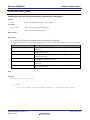
Table 3-1 shows functional differences by MCU.
Table 3-1 USB functional list by RL78 and R8C
Function
MCU type
Peripheral mode
Transmission rate possible
Host mode
Number of ports and transmission
rate
Control transfer pipes
Bulk transfer pipes
Interrupt transfer pipes
Isochronous transferr pipes
To connect HUB device when
host mode
Battery Charging
R8C/USB
R8C/34U, R8C/3MU,
R8C/34K, R8C/3MK.
1 port.
Full Speed.
R8C/34K, R8C/3MK are 1 port host.
R8C/34U, R8C/3MU peripheral only.
Full Speed.
PIPE0
PIPE4, PIPE5
PIPE6, PIPE7
Not available
Not available
RL78/USB
RL78/G1C
RL78/L1C
1 port. *1
Full Speed / Low Speed.
2 ports host *2
Full Speed / Low Speed.
Not available
Available
PIPE0
PIPE4, PIPE5
PIPE6, PIPE7
Not available
Not available
[Notes]
*1: The user can customize whether to operate the peripheral in Full Speed or Low Speed in the USB-BASIC-F/W and
UPL. Please refer to Chapter 5.6 for details.
*2: With the target board RSKRL78, host mode operation is only possible on USB-PORT1. However, it is necessary to
build the USB-BASIC-F/W with 2PORTHOST to access USB-PORT1. Please refer to Chapter 7.5 for details.
*3: USB-BASIC-F/W does not support Isochronous transfer.
3.5
Host and Peripheral Sample Vendor Demo
The USB-BASIC-F/W host sample application will exchange example data over USB when connected to a USB-BASICF/W device running as USB function (peripheral). In this sample vendor class application, data is transferred in both
directions using endpoints EP1 to EP4:
1.
The host will send a byte which is incremented from 0x00 to 0xFF using EP1 and EP3 OUT.
2.
This endpoint (EP1 and EP3 OUT) is continuously read by the peripheral demo application.
3.
The peripheral will send a byte which is incremented from 0x00 to 0xFF using EP2 and EP4 IN.
4.
This endpoints (EP2 and EP4 IN) is continuously read by the host demo application.
3.6
Note
USB-BASIC-F/W is not guaranteed to provide USB communication operation. The customer should verify operation
when utilizing it in a system and confirm the ability to connect to various USB devices.
R01AN0326EJ0213 Rev. 2.13
Mar 16, 2015
Page 6 of 107
Renesas USB MCU
4.
4.1
USB Basic Mini Firmware
Software Configuration
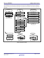
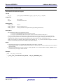
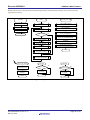
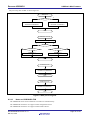
Module Configuration
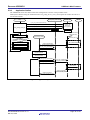
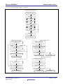
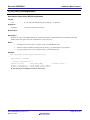
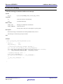
The software that composes the USB-BASIC-F/W has a "task" structure. The task hierarchy of the USB-BASIC-F/W is
shown in Figure 4.1 and the software functional overview is shown in. These tasks communicate via the scheduler using
a messaging system.
The USB-BASIC-F/W is composed of PCD (peripheral control driver - when r_usb_basic_config.h is configured as
peripheral), HCD (host control driver - when r_usb_basic_config.h is configured as host),, and MGR (USB peripheral
state management and host sequencing). The USB class driver (HDCD/PDCD), the host device driver (HDD) and an
application (APL) are not a part of USB-BASIC-F/W.
PCD operates H/W control and data transfers upon demand from UPL. It also notifies the application task when H/W
control ends, of results of data transfers, and of requests of the USB interrupt handler (status change etc).
HCD likewise operates H/W control and data transfer upon demand from the MGR task. It executes data transfers on
demand from UPL, and notifies MGR and UPL of the result of these data transfers. HCD also notifies MGR when H/W
control ends, and of requests of the USB interrupt handler (status change etc).
MGR manages the USB state of the connected device and processes sequences such as enumeration. Moreover, the USB
state of the connected device changes according to demands of UPL via API functions. To do this, MGR sends requests
to HCD to achieve this sequence processing necessary for USB state transition. (HCD then does the H/W control and
data transfers.) The result of the USB state transition is notified to UPL via callbacks.
User Programming Layer (UPL)
Peripheral Mode
Host Mode
8 Application (APL)
Scheduler Function
8 Application (APL)
Device Class Driver
7 Device driver (HDD)
6 Device Class Driver (HDCD)
6 Device Class Driver (PDCD)
4 Host Manager (MGR)
3 Host Control Driver (HCD)
2 Peripheral Control Driver (PCD)
1 USB Interrupt Handler
USB - BASIC - F/W
Hardware
Figure 4.1 Task Configuration of USB-BASIC-F/W
R01AN0326EJ0213 Rev. 2.13
Mar 16, 2015
Page 7 of 107
Renesas USB MCU
USB Basic Mini Firmware
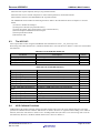
Table 4-1 Software function overview
No
1
Module Name
USB Interrupt Handler
2
Peripheral Control Driver
(PCD)
Host Control Driver
(HCD)
Host Manager
(MGR)
Device Class Driver
(PDCD/HDCD)
Host Device Driver
(HDD)
Application(APL)
3
4
5
6
7
4.2
Description
Handles all USB interrupts: USB packet transmit/receive end and special
signal detection.
Hardware control when in peripheral mode.
Peripheral transaction management.
Hardware control when in host mode
Host transaction management
Management of connected device state - enumeration.
Provided by the customer as appropriate for the system.
Rensas class driver examples are available for download.
Provided by the customer as appropriate for the system.
Rensas class driver examples are available for download.
rovided by the customer as appropriate for the system.
Rensas APL examples are available for download.
Overview of Application Program Functions
After enumeration, these are the main function of the application.
1. Data is received from the connected USB device by bulk and interrupt transfers.
2. Data is transmitted to the connected USB device by bulk and interrupt transfers.
3. The device state of the connected USB device changes when user presses SW1-3 on the RSK.
When the peripheral device is running at Low Speed, only interrupt data transfer is possible.
Switch input operation is described in Table 4-2 and Table 4-3.
Table 4-2 User switch input in host mode
Switch Function
SUSPEND
RESUME
PORTCONTROL
Description
The connected peripheral device is suspended
The connected peripheral device is resumed
VBUS output is disabled
Switch Number
SW1
SW2
SW3
Table 4-3 User switch input in peripheral mode
Switch Function
REMOTEWAKEUP
PORT OFF
PORT ON
Description
The connected host device receives Wake-up
Pull-up release of D+ or D- line
Pull-up set of D+ or D- line
R01AN0326EJ0213 Rev. 2.13
Mar 16, 2015
Switch Number
SW1
SW2
SW3
Page 8 of 107
Renesas USB MCU
4.3
USB Basic Mini Firmware
Folder Structure
The folder composition and files of USB-BASIC-F/W is shown below. USB-BASIC-F/W includes an example vendor
class application to show data transfer, and hardware resource sample code.
The project folder contains source code that controls the MCU and the evaluation board.
+ (Integrated development environment)[CS+, HEW, IAR Embedded Workbench, e2 studio]
+ (MCU name)
Project file
+ ――― HOST
Host build result
+ ――― PERI
Peripheral build result
+ src
+―――USBSTDFW[Common USB code that is used by all USB firmware]
|
+――― inc
Common header files of USB driver
|
+――― src
USB driver
+―――SmplMain[Sample application]
|
+――― APL
Sample application
+―――VENDOR [Vendor Class driver]
See Table 4-4
|
+――― inc
Common header files of vendor class driver
|
+――― src
Vendor class driver
+―――HwResource [Hardware access layer; to initialize the MCU]
+――― inc
Hardware resource header file
+――― src
Hardware resource
R01AN0326EJ0213 Rev. 2.13
Mar 16, 2015
Page 9 of 107
Renesas USB MCU
4.3.1
USB Basic Mini Firmware
List of files
Files of the USB-BASIC-F/W are listed below.
Table 4-4 List of source files
Folder
USBSTDFW\src
USBSTDFW\src
USBSTDFW\src
USBSTDFW\src
USBSTDFW\src
USBSTDFW\src
USBSTDFW\src
USBSTDFW\src
USBSTDFW\src
USBSTDFW\src
USBSTDFW\src
USBSTDFW\src
USBSTDFW\src
USBSTDFW\src
USBSTDFW\inc
USBSTDFW\inc
USBSTDFW\inc
USBSTDFW\inc
USBSTDFW\inc
SmplMain
SmplMain\APL
SmplMain\APL
SmplMain\APL
SmplMain\APL
VENDOR\src
VENDOR\src
VENDOR\src
VENDOR\src
VENDOR\inc
R8C3xx\src\Hw
Resource\src
R8C3xx\src\Hw
Resource\inc
RL78xxx\src\Hw
Resource\src
RL78xxx\src\Hw
Resource\inc
File Name
r_usb_cstdapi.c
r_usb_cstdfunction.c
r_usb_h1port.c
r_usb_h2port.c
r_usb_hbc.c
r_usb_hdriver.c
r_usb_hdriverapi.c
r_usb_hp0function.c
r_usb_hp1function.c
r_usb_pbc.c
r_usb_pdriver.c
r_usb_pdriverapi.c
r_usb_hport.h
r_usb_iodefine.h
r_usb_api.h
r_usb_cdefusbip.h
r_usb_ckernelid.h
r_usb_ctypedef.h
r_usb_usrconfig.h
main.c
r_usb_vendor_descriptor.c
r_usb_vendor_hapl.c
r_usb_vendor_papl.c
r_usb_vendor_apl.h
r_usb_vendor_hapi.c
r_usb_vendor_hdriver.c
r_usb_vendor_papi.c
r_usb_vendor_pdriver.c
r_usb_vendor_api.h
ncrt0.a30
adc_driver_r8c.c
lcddriver_r8c.c
r8cusbmcu.c
iodefine_r8c.h
nc_define.inc
sect30.inc
hw_resource.h
r_usb_usbip.h
adcdriver.c
csi_driver.c
keydriver.c
lcddriver.c
leddriver.c
rl78usbmcu.c
hw_resource.h
r_usb_usbip.h
R01AN0326EJ0213 Rev. 2.13
Mar 16, 2015
Description
USB library API functions
USB library functions
1-port host functions
2-port host functions
USB HBC control functions
USB Host Control Driver
HCD API functions
Port 0 control functions
Port 1 control functions
USB PBC control functions
USB Peripheral Control Driver
PCD API functions
Prototype declarations of USB host functions
Macro definitions for USB register access
Prototype declaration of USB API functions
Macro definition for USB-BASIC-F/W
Macro definition for scheduler functions
Type definition of USB-BASIC-F/W
Macro definitions for user configuration
Main process
Descriptor and endpoint information
Host sample application program
Peripheral sample application program
Macro definions for the application
Sample HDCD API
Sample HDCD (host class driver)
Sample PDCD API
Sample PDCD (peripheral class driver)
Prototype declaration of Vendor class driver
Startup program
AD converter driver
LCD driver
MCU control processing
IO define header
Macro Symbol definition
Section define
Prototype declarations of special function driver
USB register declarations
AD converter driver
CSI driver
KEY driver
LCD driver
LED driver
MCU control processing
Prototype declaration of special function driver
USB register declarations
Notes
Page 10 of 107
Renesas USB MCU
USB Basic Mini Firmware
4.4
System Resources
4.4.1
Definitions
Table 4-5 and Table 4-6 list the Task ID and the task priorities used when registering the USB-BASIC-F/W modules with
the scheduler. These are defined in the r_usb_ckerneid.h header file.
Table 4-5 Scheduler Registration IDs when Host
Scheduler registration task
Task ID: USB_HVEN_TSK
Task ID: USB_HSMP_TSK
Task ID: USB_HCD_TSK
Task ID: USB_MGR_TSK
Mailbox ID / Default receive task
USB_HVEN_MBX / USB_HVEN_TSK
USB_HSMP_MBX / USB_HSMP_TSK
USB_HCD_MBX / USB_HCD_TSK
USB_MGR_MBX / USB_MGR_TSK
Description
HDCD (R_usb_hvndr_Task)
Priority 2
APL (usb_hsmpl_apl_task)
Priority 3
HCD (R_usb_hstd_HcdTask)
Priority 0
MGR (R_usb_hstd_MgrTask)
Priority 1
Message description
Mailbox ID and receive task ID of
APL -> HDCD messages
Mailbox ID and receive task ID of
HDCD -> APL messages
HCD mailbox and its task ID
MGR mailbox and its task ID
Notes
Notes
Table 4-6 Scheduler Registration IDs when Peripheral
Scheduler registration task
Task ID: USB_PVEN_TSK
Task ID: USB_PSMP_TSK
Task ID: USB_PHCD_TSK
Mailbox ID / Default receive task
USB_PVEN_MBX / USB_PVEN_TSK
USB_PSMP_MBX / USB_PSMP_TSK
USB_PCD_MBX / USB_PCD_TSK
4.5
Description
PDCD (R_usb_pvndr_Task)
Priority 3
APL (usb_psmpl_apl_task)
Priority 4
PCD (R_usb_pstd_PcdTask)
Priority 0
Message description
Mailbox ID and receive task ID of
APL -> PDCD messages
Mailbox ID and receive task ID of
PDCD -> APL messages
PCD task mailbox and task ID
Notes
Notes
Customization, Notes
The customer will need to make a variety of customizations, depending on USB class, differences in system
configuration,. Other customizations are transmission rate and program ROM/RAM size, or settings that affect the user
interface(Key & LCD etc…).
R01AN0326EJ0213 Rev. 2.13
Mar 16, 2015
Page 11 of 107
Renesas USB MCU
5.
USB Basic Mini Firmware
Peripheral Sample Program (UPL)
This chapter exemplifies the case when the RL78 MCU is used, but applies in general to all devices running the USBBASIC-F/W. Low Speed devices cannot communicate using bulk transfer, so skip descriptions concerning bulk transfer
when the user system is Low Speed, for example when using Low-speed not support MCU.
5.1
Operation Environment
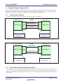
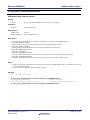
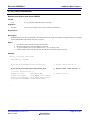
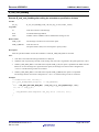
The Figure 5.1 and Figure 5.2 show a sample operating environment for the software.
USB cable
Peripheral Vendor device
Host Vendor device
Enumeration
(PIPE0 control transfer)
RSK Board
USB
PORT
Data communication
(PIPE4, PIPE5 bulk transfer)
USB
PORT
RSK Board
Data communication
(PIPE6, PIPE7 interrupt transfer)
Vendor class driver
+
Vendor class driver
+
USB-BASIC-F/W
USB-BASIC-F/W
Figure 5.1 Example Full Speed Operation Environment
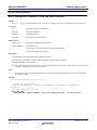
Peripheral Vendor device
USB cable
Host Vendor device
Enumeration
(PIPE0 control transfer)
RSK Board
USB
PORT
USB
PORT
RSK Board
Data communication
(PIPE6, PIPE7 interrupt transfer)
Vendor class driver
+
Vendor class driver
+
USB-BASIC-F/W
USB-BASIC-F/W
Figure 5.2 Example Low Speed Operation Environment
5.2
Description of Peripheral Sample Program
The peripheral sample program of the USB-BASIC-F/W operates in Full Speed or Low Speed, as configured by the
user in r_usb_usrconfig.h. The sample program includes a vendor class driver and a sample application for data transfer.
The data communication using bulk transfer uses pipes 4 and 5, and data communication using interrupt transfer uses
pipes 6 and 7.
R01AN0326EJ0213 Rev. 2.13
Mar 16, 2015
Page 12 of 107
Renesas USB MCU
USB Basic Mini Firmware
When creating a customer class driver or an application, refer to files r_usb_vendor_papl.c, r_usb_vendor_descriptor.c,
and r_usb_vendor_pdriver.c.
The following settings are necessary in order to communicate when running as a USB peripheral.
1. Select Full Speed or Low Speed.
2. Set up the scheduler (number of tasks, table size, task ID, mailbox ID, etc.)
3. Call a application task in main loop.
4. Create a device descriptor table so that the bus’s host (at the other end of the USB bus) will select the correct host
device class driver at enumeration.
5. Create a pipe information table, so the bus’s host device class driver can query the peripheral what endpoints to use.
6. Return data according to the received USB host requests.
5.2.1
Sunmary of Functionality
(1). Sample application
A USB state transition inside PCD will cause the registered vendor driver’s callback to execute. The UPL is
thereby notified of events. When the USB state transition USB_STS_CONFIGURED occurs are initialize
processing, and sample application data transfer is requested from the vendor class driver. Bulk transfers use
PIPE4 and 5 and interrupt transfers use PIPE6 and 7. When the vendor class driver is notified of the end of a
data transfer (via function g_usb_SmplTrnMsg[pipe].complete), the sample applcation data transfer is restarted
using the same pipe.
When USB_STS_SUSPEND is issued from the USB-BASIC-F/W, UPL executes the STOP/WAIT instruction.
User key input is received during regular processing. Example code for remote wake up (from suspend state),
and port enable/disable are included.
(2). Vendor class driver
Initialize processing according to the USB state that is notified from APL which call
R_usb_pstd_PcdChangeDeviceState() . Data transfer is requested by the application to USB-BASIC-F/W, which
executes the transfer. End of data transfer is notified to the application by USB-BASIC-F/W. Vendor class
driver does not support to the vendor class request.
(3). Enumeration
When the USB host detects a connection, USB Host starts enumeration. An enumeration ends normally if a
vendor class driver is registered in the USB host, and USB_STS_CONFIGURED is notified to the application
by a callback function.
(4). Data communication
When enumeration ends normally, data transfer is possible. The application can begin data transfer when the
USB state transition callback occurs.
Vendor class request
A vendor class request is not issued. (STALL response.)
(5). USB state transition
After the vendor driver is registered together with its callback, USB state transitions can be monitored by the
user.
USB_STS_DETACH:
Stop the data transfer
USB_STS_DEFAULT:
Initialized data transfer size, Initialized configuration number
USB_STS_ADDRESS:
Initialized configuration number
USB_STS_CONFIGURED:
Initialized data toggle buffer, Start the data transfer
USB_STS_SUSPEND:
Interrupt the data transfer, Execute the STOP/WAIT instruction
USB_STS_RESUME:
Restart the data transfer
The sample application returns from the suspended state by a resume signal. Moreover, it is also possible for the
peripheral application to demand remote wake up from USB-BASIC-F/W.
(6). USB device framework
R01AN0326EJ0213 Rev. 2.13
Mar 16, 2015
Page 13 of 107
Renesas USB MCU
USB Basic Mini Firmware
Operation can be confirmed using a device framework test with USBCommandVerifier.exe (USBCV)
distributed from the USB Implementers Forum (USB-IF). A supported test item is Chapter 9 only. To run
USBCV you will likely need a High Speed hub between the host and the device.
5.2.2
(1).
Operation of Peripheral Sample Program
Initialization
For HEW
When performingAfter hardware reset for aof the MCU device, the _PowerON_Reset_PC function, in
ncrt0.a30/resetprg, is called. The reset function initializes the MCU via and call the hardware initializationv
function usb_cpu_mcu_initialize() function. When returning from the hardware initialization function, initialize
mMemory areas are then initialized, and calls finally the main() function, in main.c, is calledfile. For more
details of startup processing, refer to the hardware manaulHM and the integrated development environment
manual.
For CS+
When performing hardware reset for a device, the _@cstart function of a startup file created using the CS+ is
called. The startup function initializes the MCU, and call the hardware initialization function hdwinit() function
of the user definition. When returning from the hardware initialization function, initialize memory areas such as
saddr area and call the main() function in the main.c file. For more details of startup processing, refer to the
hardware manaulHM and the integrated development environment manual.
(2).
Main function processing
The main() function initializes the system via the usb_psmpl_main_init() function (initialization of target MCU
and board, initialization of the USB module, start of USB-BASIC-F/W, registration of the UPL driver, and
setting operation permission of the USB module), the program is in the static state, and will wait for a request in
the main loop.
Operation in the main loop are as follows:
(1) Determine if the scheduler has a request pending.
(2) If processing is requested, start a task.
(3) Perform static processing.
(4) Return to (1).
(3).
Sample application task (usb_psmpl_apl_task())
When an enumeration ends normally, the sample application initializes global variables and requests the start of
the demonstration data transfer using the API function R_usb_pvndr_TransferStart(). When a transfer end
callback is received from the vendor class driver, the data transfer is repeated (R_usb_pvndr_TransferStart is
called again).When state USB_STS_SUSPEND ocurrs in USB-BASIC-F/W, the APL executes the STOP/WAIT
instruction via the usb_cpu_stop_mode() function.
(4).
Vendor class driver (R_usb_psmpl_VendorTask())
When data transfer is requested by the sample application, the vendor class driver (PDCD) demands the data
transfer of USB-BASIC-F/W using the API function R_usb_pstd_TransferStart(). Moreover, the end of the data
transfer is notified to the application via the callback function when the callback for data transfer end is called
from USB-BASIC-F/W.
When the USB state transition is notified to the sample application, the vendor class driver initializes the
following global variables according to the USB state.
USB_STS_CONFIGURED
Keep the configuration number, and initialize the global variable of the DATA-PID table.
USB_STS_DETACH, USB_STS_ ADDRESS, USB_STS_ DEFAULT
"0" cleared of configuration number.
USB_STS_SUSPEND, USB_STS_RESUME
No processing.
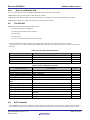
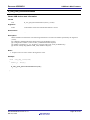
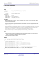
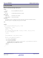
Figure 5.3 shows the outline flow of the UPL.
R01AN0326EJ0213 Rev. 2.13
Mar 16, 2015
Page 14 of 107
Renesas USB MCU
USB Basic Mini Firmware
The USB-BASIC-F/W comprises tasks that implement control functions for USB data transmit and receive operations.
When an interrupt occurs, a notification is sent by means of a message to the USB-BASIC-F/W. When the USB-BASICF/W receives a message from the USB interrupt handler, it determines the interrupt source and executes the appropriate
processing.
H/W reset
MCU initialization
Main
Main()
System initialization
usb_psmpl_main_init()
Initialization
usb_psmpl_main_init()
Target board initialization
usb_cpu_target_init()
usb_cpu_mcu_initialize()
Memory initialization
Go to main()
USB IP initialization
R_usb_pstd_PcdChangeDeviceState()
Scheduler
R_usb_cstd_Scheduler()
Task processing?
No
Driver open
R_usb_pstd_PcdOpen()
Driever registration
R_usb_pstd_DriverRegistration()
Yes
PCD task
R_usb_pstd_PcdTask()
Set operation mode(Peripheral)
R_usb_pstd_PcdChangeDeviceState()
PDCD task
R_usb_psmpl_VendorTask()
return
Application task
usb_psmpl_apl_task()
Key processing
usb_psmpl_keyprocess()
Standby processing
usb_cpu_stop_mode()
usb_cpu_usb_interrupt
Each task
Clear interrupt status
USB_RCV_MSG?
Send a message of
processing request to
PCD task
Scheduler
No
Yes
Task
processing
Processing request?
No
Yes
Select request with
top priority
return
return
return
Figure 5.3 Sequence Outline
R01AN0326EJ0213 Rev. 2.13
Mar 16, 2015
Page 15 of 107
Renesas USB MCU
5.2.3
USB Basic Mini Firmware
Setting a Scheduler
Set the maximum value of a task ID and maximum number of messages stored in the task priority table in the
r_usb_cstd_kernelid.h file.
/* Please set user system */
#define
USB_IDMAX
#define
USB_TABLEMAX
#define
USB_BLKMAX
5.2.4
((uint8_t)5)
((uint8_t)5)
((uint8_t)5)
/* Maximum Task ID +1 */
/* Maximum priority table */
/* Maximum block */
Setting a Task ID and Mail Box ID
Set a task ID and mailbox ID in the file r_usb_cstd_kernelid.h.The task priority level is the same as task ID. (When
the task identification number is small, priority is high.)
#define
USB_PCD_TSK
USB_TID_0
/* Peripheral Control Driver Task */
#define
USB_PCD_MBX
USB_PCD_TSK
/* Mailbox ID */
#define
USB_PVEN_TSK
USB_TID_3
/* Vendor Class Driver ID */
#define
USB_PVEN_MBX
USB_PVEN_TSK
/* Mailbox ID */
#define
USB_PSMP_TSK
USB_TID_4
/* Peripheral Sample Application Task */
#define
USB_PSMP_MBX
USB_PSMP_TSK
/* Mailbox ID */
5.2.5
Task calling
Call a task to be used in main loop (main() function).
void main(void)
{
/* Initialized USBIP hardware */
usb_psmpl_main_init();
/* Sample main loop */
while( 1 )
{
if( R_usb_cstd_Scheduler() == USB_FLGSET )
{
R_usb_pstd_PcdTask();
/* PCD Task */
R_usb_psmpl_VendorTask();
usb_psmpl_apl_task();
}
keydata = usb_smpl_KeyRead();
if (keydata != 0x00)
{
usb_psmpl_keyprocess(keydata);
}
if ( g_usb_suspend_flag == USB_YES )
{
usb_cpu_stop_mode();
}
}
5.2.6
Starting the UPL
The USB-BASIC-F/W (running as USB function) has established a connection with a host when a
SET_CONFIGURATION request is received. This is notified to the UPL via the callback function
g_usb_PcdDriver.statediagram. The USB state of the second argument must be analyzed, and suitable user
processing can then take place (the user application can start). The sample application notifies the USB state to the
vendor class driver, initializes the data area, and starts example application data transfers. Note that the vendor class
driver must memorize the configuration number when SET_CONFIGURATION occurs.
R01AN0326EJ0213 Rev. 2.13
Mar 16, 2015
Page 16 of 107
Renesas USB MCU
5.2.7
USB Basic Mini Firmware
Responding to a USB Request
A program example of control transfer for a received host class request, using the API function provided by USBBASIC-F/W, is shown below.
void usb_psmp_ControlTransfer(usb_request_t* request, uint16_t ctsq)
{
g_usb_psmp_Request = request;
if ((g_usb_psmp_Request.wRequest & USB_BMREQUESTTYPETYPE) == USB_CLASS)
{
switch( ctsq )
{
case USB_CS_IDST: usb_psmp_control_trans0(request); break;
case USB_CS_RDDS: usb_psmp_control_trans1(request); break;
case USB_CS_WRDS: usb_psmp_control_trans2(request); break;
case USB_CS_WRND: usb_psmp_control_trans3(request); break;
case USB_CS_RDSS: usb_psmp_control_trans4(request); break;
case USB_CS_WRSS: usb_psmp_control_trans5(request); break;
case USB_CS_SQER:
R_USB_pstd_ControlEnd((uint16_t)USB_DATA_ERR); break;
default:
R_USB_pstd_ControlEnd((uint16_t)USB_DATA_ERR); break;
}
}
else
{
R_USB_pstd_SetStallPipe0();
}
}
1. Data stage processing
Transfer data to the USB host using the API function R_usb_pstd_ControlRead()/R_usb_pstd_ControlWrite() for
supported requests *. Call the API function R_usb_pstd_SetStallPipe0()to return STALL to a USB host for an
unsupported request.
2. Status stage processing
If the data stage ends properly, call the API R_usb_pstd_ControlEnd() and specify USB_CTRL_END as the status
argument. . If the data stage does not end properly, specify instead SB_DATA_ERR.
*USB-BASIC-F/W accesses the user buffer up to the data size specified with API function R_usb_pstd_ControlRead() /
R_usbh_pstd_ControlWrite(). Therefore, make sure that the capacity of the user buffer exceeds the transmit / receive data
size specified in the control transfer data stage.
R01AN0326EJ0213 Rev. 2.13
Mar 16, 2015
Page 17 of 107
Renesas USB MCU
5.2.8
USB Basic Mini Firmware
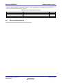
Application Outline
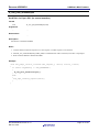
The USB-BASIC-F/W starts data transfer after configuration as shown in the procedure below.
Identify the USB state using the callback function usb_psmpl_device_state(), and request the vendor class driver to
execute data transfer.
main()
R_usb_psmpl_VendorTask()
USB-BASIC-F/W
HOST
R_usb_pstd_PcdChangeDeviceState()
usb_psmpl_main_init
R_usb_pstd_PcdOpen()
Initialize HW
Start PCD
R_usb_pstd_DriverRegistration()
Driver Registration
R_usb_pvndr_DriverStart()
Start PDCD
R_usb_pstd_PcdChangeDeviceState()
HW setting
USB host connected
(VBUS detected)
R_usb_cstd_Scheduler
usb_psmpl_apl_task()
Data line pull up
Task operated?
No
Enumeration
Yes
R_usb_pstd_PcdTask
SET_CONFIGURATION
Callback statediagram
R_usb_psmpl_VendorTask
usb_psmpl_device_state()
R_usb_pvndr_StateCallback()
usb_psmpl_apl_task
usb_smpl_data_initilized()
Initialize data area
usb_psmpl_tranfer_start()
Start data transfer
R_usb_pvndr_TransferStart()
R_usb_pvndr_TransferStart()
R_usb_pstd_TransferStart()
R_usb_pstd_TransferStart()
R_usb_pvndr_TransferStart()
data transfer start request
Data transfer
Callback Complete
Callback Complete
Transfer end
usb_pvndr_transfer_result()
usb_psmpl_transfer_result()
Figure 5.4 Application Operation Outline
R01AN0326EJ0213 Rev. 2.13
Mar 16, 2015
Page 18 of 107
Renesas USB MCU
5.3
USB Basic Mini Firmware
Data Transfer
User data transfer is customer-specific as to when it occurs, transfer method, start or end timing. The message buffer
size and structure needs to change based on the application.
5.3.1
Basic specification
Inside USB-BASIC-F/W, data transfer occurs using the user’s buffer pointed to by the USB Data Transfer Structure
usb_utr_t. See Table 6-3.When data transfer ends, the USB-BASIC-F/W sets PID = NAK and notifies the transfer
end by the callback function.
The USB-BASIC-F/W updates the pipe status (utr_table.pipectr) specified when the data transfer is demanded.
Moreover, the pipe status (data toggle) is notified by the callback at data transfer end. Therefore, because UPL
memorizes the pipe status, the data transfer of multiple endpoints is possible using one pipe. The pipe status however
should be initialized to “DATA0" at USB reset, STALL release, SET_CONFIGURATION request, and at
SET_INTERFACE request, etc.
The size of the max packet of the Bulk pipe is fixed at 64 bytes and should not be changed.
5.3.2
Data Transfer Request
Use R_usb_pstd_TransferStart() to start a UPL data transfer.
5.3.3
Notification of Transfer Result
Data transfer end is notified to the UPL using the callback function specified in the usb_utr_t transfer structure. Refer
to Table 6-7 for how to handle the content of the transfer structure.
5.3.4
Notes on Data Transmission
1.
Not support the continuous transfer using the sampe pipe.
2.
Not be able to tranfer the next data until the callback function is called.
5.3.5
Notes on Data Reception
(1) Use a transaction counter for the receive pipe.
When a short packet is received at the end of a data transfer, the expected remaining receive data length is stored
in tranlen of the usb_utr_t structure. When the received data exceeds the buffer size, data read from the FIFO
buffer up to the buffer size and this transfer ends. When the user buffer area is insufficient to accommodate the
transfer size, the usb_cstd_forced_termination() function may clear the receive packet.
(2) Receive callback
When the received data is n times of the maximum packet size but less than the expected received data length,
the data transfer is not considered to be ended and so a callback is not generated. Only when receiving a short
packet or the data size is matched, the USB-BASIC-F/W judges the transfer ended and generates the callback.
Example
When the data size of the reception schedule is 128 bytes and the maximum packet size is 64 bytes:
1 to 63 bytes received
A received callback is generated.
64 bytes received
A receive callback is not generated.
65 to 128 bytes received
A receive callback is generated.
5.3.6
Data Transfer Outline
R01AN0326EJ0213 Rev. 2.13
Mar 16, 2015
Page 19 of 107
Renesas USB MCU
USB Basic Mini Firmware
To transfer data, set the necessary information in the transfer structure usb_utr_t structure and call
R_usb_pstd_TransferStart(). An example data transfer is shown below.
void usb_pvndr_transfer_start( uint16_t pipe )
{
g_usb_PsmplTrnMsg[pipe].pipenum
= pipe;
g_usb_PsmplTrnMsg[pipe].tranadr
= g_usb_PsmplTrnPtr[pipe];
g_usb_PsmplTrnMsg[pipe].tranlen
= g_usb_PsmplTrnSize[pipe];
g_usb_PsmplTrnMsg[pipe].pipectr
= g_usb_PsmplPipeCtr[pipe];
g_usb_PsmplTrnMsg[pipe].setup
= USB_NULL;
g_usb_PsmplTrnMsg[pipe].complete
= (usb_cb_t)&usb_pvndr_transfer_result;
R_usb_pstd_TransferStart((usb_utr_t *)&g_usb_PsmplTrnMsg[pipe]);
}
An example of a callback function (executed when at the end of the transfer and notified to UPL via a scheduler
message) is shown below.
void usb_pvndr_transfer_result(usb_utr_t *mess)
{
usb_er_t
err;
mess->msginfo = USB_SMPL_TRANSFER_END;
err = R_USB_SND_MSG(USB_PVEN_MBX, (usb_msg_t*)mess);
if( err != USB_E_OK )
{
while(1);
}
}
5.4
Pipe Information
Pipe settings for the peripheral class driver need to be created in the form of a ”Pipe Information Table”. A pipe
information example for a peripheral vendor class driver is in uint16_t g_usb_psmpl_EpTbl1[], in the
r_usb_vendor_descriptor.c file.
5.4.1
Pipe Information Table
A Pipe Information Table comprises the following four items (uint16_t 4).
1.
2.
3.
4.
5.4.2
Pipe window select register (address 0x64)
Pipe configuration register (address 0x68)
Pipe maximum packet size register (address 0x6C)
Dummy data (not possible to delete)
Pipe Definition
The pipe information table structure used in the peripheral sample program is shown below. The macros are defined
in the r_usb_cstd_defusbip.h file. Refer to the header file for pipe definition values.
Structure example of pipe information table:
uint16_t g_usb_psmpl_EpTbl1[] =
Pipe information table
{
USB_PIPE4,
Pipe definition item 1
USB_BULK | USB_BFREOFF | USB_DBLBON | USB_SHTNAKON | USB_DIR_P_IN | USB_EP4,
← Pipe definition item 2
R01AN0326EJ0213 Rev. 2.13
Mar 16, 2015
Page 20 of 107
Renesas USB MCU
USB Basic Mini Firmware
USB_MAX_PACKET(64),
Pipe definition item 3
USB_NULL,
Dummy data
:
USB_PDTBLEND,
}
(1). Pipe definition item 1: Specify the values to be set in the pipe window select register.
Pipe select: Specify the selected pipes (USB_PIPE4 to USB_PIPE7).
(2). Pipe definition item 2: Specify the values to be set in the pipe configuration register.
Transfer type
: Specify either USB_BULK or USB_INT
BRDY operation designation
: Specify USB_BFREOFF
Double buffer mode
: Specify either USB_DBLBON or USB_DBLBOFF
SHTNAK operation designation
: Specify either USB_SHTNAKON or USB_SHTNAKOFF
Transfer direction
: Specify either USB_DIR_P_OUT or USB_DIR_P_IN
Endpoint number
: Specify the endpoint number (EP1 to EP15) to the pipe
The settable values differ depending on the pipes for the transfer type. For details, refer to the HM.
Describe the pipe information according to the endpoint descriptor.
Set USB_SHTNAKON for the receive direction pipe (USB_DIR_P_OUT).
(3). Pipe definition item 3: Specify the maximum packet size of the endpoint.
Specify the maximum packet size: Set the value based on the USB specification.
Specify the maximum packet size of the endpoint.
(4). Others.
The pipe information is necessary somultiple endpoints can be used to communicate simultaneously.
Synchronize communication for each transfer associated with the UPL.
Write USB_PDTBLEND at the end of the table.
Register the pipe information table using the R_usb_pstd_DriverRegistration() function.
When the SET_CONFIGURATION request is received, set the pipe information to a register in the
USB-BASIC-F/W.
The pipe information does not support alternate interface setting.
R01AN0326EJ0213 Rev. 2.13
Mar 16, 2015
Page 21 of 107
Renesas USB MCU
5.5
USB Basic Mini Firmware
Descriptor Information
It is necessary to create descriptors according to the customer system. In the peripheral sample program, a sample table
of descriptors is found in file r_usb_vendor_descriptor.c.
The descriptor definitions comprise the following three types.
1. Standard Device Descriptor
uint8_t g_usb_psmpl_DeviceDescriptor[]
2. Configuration/Other_Speed_Configuration/Interface/Endpoint
uint8_t g_usb_psmpl_ConfigurationF_1[]
3. String Descriptor
uint8_t g_usb_psmpl_StringDescriptor0[]
uint8_t g_usb_psmpl_StringDescriptor1[]
uint8_t g_usb_psmpl_StringDescriptor2[]
uint8_t g_usb_psmpl_StringDescriptor3[]
uint8_t g_usb_psmpl_StringDescriptor4[]
1).
ID registration
Set a vendor ID and product ID as in the example. Do not use the default values in a product.
Example) If you own the Vendor ID 0x0000, and wish to use product ID = 0x00FF, set
#define USB_VENDORID (0x0000u)
#define USB_PRODUCTID
(0x00FFu)
2).
/* Vendor ID */
/* Product ID */
Device information
Set device information depending on selected speed.
#ifdef USB_LSPERI_PP
#define USB_PVDR_BLENGTH 32
/* Low Speed (PIPE 6-7) */
#define USB_DCPMAXP
(8u)
/* DCP max packet size */
#define USB_EPNUMS
(2)
/* Endpoint number */
#define USB_INTEPMAXP
(8u)
/* Interrupt pipe max packet size */
#endif /* USB_LSPERI_PP */
#ifdef USB_FSPERI_PP
#define USB_PVDR_BLENGTH 46
/* Full Speed (PIPE 4-7) */
#define USB_DCPMAXP
(64u) /* DCP max packet size */
#define USB_EPNUMS
(4)
/* Endpoint number */
#define USB_INTEPMAXP
(64u) /* Interrupt pipe max packet size */
#endif /* USB_FSPERI_PP */
3).
Other information
Set the following information expanded to a descriptor.
#define USB_BCDNUM
(0x0200u)
#define USB_RELEASE
(0x0100u)
#define USB_CONFIGNUM
(1u)
4).
1.
2.
3.
/* bcdUSB */
/* Release Number */
/* Configuration number */
Notes
For more details of each descriptor, refer to Chapter 9 of USB specification Revision 2.0.
When changing a descriptor definition, change the pipe information table (sample table is in
r_usb_vendor_descriptor.c) according to the endpoint descriptor.
Serial number must start from 0 for the interface number.
R01AN0326EJ0213 Rev. 2.13
Mar 16, 2015
Page 22 of 107
Renesas USB MCU
5.6
USB Basic Mini Firmware
Operating USB-BASIC-F/W in Peripheral Mode
This chapter describes the procedure to operate the USB-BASIC-F/W in peripheral mode. See also the sample code.
5.6.1
Select a device
Table 5-1 lists the integrated development environment of each device for USB-BASIC-F/W . Use the H/W resource
folder that corresponds to the device.
Table 5-1 Hardware Resource of Sample Code
Integrated
development
environment
Data rate
R8C/3MU,
R8C/34U,
R8C/3MK,
R8C/34K
HEW
Full Speed
RL78/G1C
CS+
RL78/L1C
CS+
Device
5.6.2
Hardware Resource Folder
Full Speed src\HwResource
Low Speed
Full Speed
Low Speed
User Configuration file (r_usb_usrconfig.h)
Configure the User Definition Information file (r_usb_usrconfig.h) in the “inc” folder, to set the functionality of the
USB-BASIC-F/W. Settable items are shown below.
(1). Specify data transfer rate (only RL78/USB)
Set the data transfer rate of the USB communication. Make the macro in operation effective.
// #define
USB_LSPERI_PP
// LowSpeed peripheral device
#define
USB_FSPERI_PP
// FullSpeed peripheral device
(2). Specify the function to change the global variable to the static variable.
Add the follow.
#define
USB_STATIC_USE
(3). Specify the function to use the fook function when the error is generated.
Add the follow
#define
USB_DEBUG_HOOK_USE
(4). Specify battery charging operation (only RL78/USB)
Set the battery charging operation. Make the macro in operation effective.
#define
USB_PERI_BC_ENABLE
Enable batetry charging
R01AN0326EJ0213 Rev. 2.13
Mar 16, 2015
Page 23 of 107
Renesas USB MCU
USB Basic Mini Firmware
The following definition is defined by the project file of the integration environment.
5.6.3
RL78G1C/RL78L1C
:
R8C
:
USB_FUNCSEL_PP = USB_PERI_PP
RL78USB
USB_FUNCSEL_PP = USB_PERI_PP
R8CUSB
Changing USB-BASIC-F/W
The code shown below is subject to change, though sample functions for the Renesas USB MCU are already provided.
Change them according to the user system. The functions that are subject to change are listed in Table 5-2, with the
functionality they implement:
Initialization of the MCU (clock, pin and port setup…), interrupt handling, etc.
The wait functions (usb_cpu_delay_xms() and usb_cpu_delay_1u()) generate the wait time. Change the number of
loops according to the system design.
Use the function usb_cpu_int_enable() to enable the USB interrupt in order to use the scheduler function.
usb_cpu_int_disable() will stop the scheduler from detecting USB acitivity.
The message is sent to PCD task from the USB interrupt by generating the USB interrupt. The scheduler executes
the task control and call PCD task.
Table 5-2 USB-BASIC-F/W Function List
Type
void
void
Function Name and argument
usb_cpu_mcu_initialize(void)
usb_cpu_target_init(void)
void
void
void
void
void
void
void
void
void
void
void
usb_cpu_set_pin_function(void)
usb_cpu_usb_interrupt (void)
usb_cpu_usbint_init (void)
usb_cpu_int_enable(void)
usb_cpu_int_disable(void)
usb_cpu_intp0_enable(void)
usb_cpu_intp0(void)
usb_cpu_usb_resume_interrupt(void)
usb_cpu_delay_1us(uint16_t time)
usb_cpu_delay_xms(uint16_t time)
usb_cpu_stop_mode(void)
R01AN0326EJ0213 Rev. 2.13
Mar 16, 2015
Description
MCU initialization (oscillation control, etc.)
System initialization (pin config, port and interrupts
setup, etc.
USB function setting of the MCU(pin setting, etc.)
USB interrupt handler
USB interrupt enabled
USB interrupt enabled for the scheduler
USB interrupt disabled for the scheduler
Enable INTP0 interrupt for the swtich for RSK
INTP0 interrupt for the swtich for RSK
USB interrupt handler for USB resume
1 s wait processing
1 ms wait processing
Execute the STOP instruction
Page 24 of 107
Renesas USB MCU
6.
USB Basic Mini Firmware
Peripheral Controller Driver (PCD)
6.1
Basic Function
PCD is a program to control the hardware when operating target devices as USB functions. The USB-BASIC-F/W
analyzes requests issued from the UPL and controls the hardware. The hardware control result is notified to UPL using a
return value or callback function. Requests to the hardware are made from the UPL The results are made known to UPL
via the callback function that was registered to the USB-BASIC-F/W using the driver information structure. Start the
USB-BASIC-F/W as shown in chapter 6.2.1 and register the UPL as shown in 6.2.3 to configure USB-BASIC-F/W as a
peripheral.
The fFunctions of the PCD include:
1.
2.
3.
4.
5.
Detection of USB state change with the connected host, and notification ofthe result. See chapter 6.2.3
Enumeration with the host: See 6.2.7
Notification of USB requests: 6.2.4
Data transfer and notification of transfer result: 6.2.5
USB state control (USB state control and notification of control result): 6.2.6
6.2
6.2.1
Operation Outline
Starting the PCD
Start the USB-BASIC-F/W using API function R_usb_pstd_PcdOpen().
6.2.2
Registration of UPL
The UPL registers information shown in Table 6-1 to the USB-BASIC-F/W using the API function
R_usb_pstd_DriverRegistration()
The USB-BASIC-F/W preserves this information in the global variable (g_usb_PcdDriver).
typedef struct
{
uint16_t
uint8_t
uint8_t
uint8_t
usb_cb_info_t
usb_cb_trn_t
} usb_pcdreg_t;
*pipetbl;
*devicetbl;
*configtbl;
**stringtbl;
statediagram;
ctrltrans;
/*
/*
/*
/*
/*
/*
Pipe definition table address */
Device descriptor table address */
Configuration descriptor table address */
String descriptor table address */
Device status */
Control transfer */
Table 6-1 Members of the usb_pcdreg_t Structure
Members
*pipetbl
*devicetbl
*configtbl
**stringtbl
statediagram
ctrltrans
Functions
Register the address of the Pipe Information Table.
Register the address of the Device Descriptor table.
Register the address of the Configuration Descriptor table.
Register the address of the String Descriptor address table.
Register the function to start when the USB state transits.
Register the function to start when a class request or vendor request is
issued.
R01AN0326EJ0213 Rev. 2.13
Mar 16, 2015
Notes
Page 25 of 107
Renesas USB MCU
6.2.3
USB Basic Mini Firmware
Notification of USB State Change
To notify UPL of a USB state transition etc, the USB-BASIC-F/W executes USB state transition callback function
(*g_usb_PcdDriver.statediagram) that the user previously registered with USB-BASIC-F/W. The USB-BASIC-F/W
notifies the information below to the UPL using the second argument of the callback function. Analyze the USB state
and perform suitable processing to the system.
USB state transition
USB_ STS_DETACH:
USB_ STS_ATTACH:
USB_ STS_DEFAULT:
USB_ STS_ADDRESS:
USB_ STS_CONFIGURED:
USB_ STS_SUSPEND:
USB_ STS_RESUME:
USB_PORTENABLE:
6.2.4
Detach detection
Attach detection
Default state transition (USB bus reset detection)
Address state transition (Set_Address request reception)
Configured state transition (Set_Configuration request reception)
Suspend state transition (suspend detection)
Suspend state cancellation (resume detection)
Pull up the D+ (RL78/USB contain the case where "Pull up D-"
Control Transfer Notification
The USB-BASIC-F/W automatically returns standard requests when enumerating to a USB host. See 6.2.7). When a
device class (a vendor class) request is received, the control transfer callback function (*g_usb_pstd_Driver.ctrltrans),
registered in the USB-BASIC-F/W, is executed. The USB-BASIC-F/W notifies the UPL of the information shown in
R01AN0326EJ0213 Rev. 2.13
Mar 16, 2015
Page 26 of 107
Renesas USB MCU
USB Basic Mini Firmware
Table 6-2 using the first argument of the callback function. The UPL must analyze a USB request and perform
appropriate processing.
The following standard requests will trigger the control transfer callback to execute.
When receiving Get_Descriptor request and bRecipient is an interface.
When receiving Clear_Feature request or Set_Feature request.
These standard request types are notified via the second argument of the callback:
USB_CLEARSTALL
Receive Clear_Feature request (Clear STALL)
USB_CLEARREMOTE
Receive Clear_Feature request (Disable remote wakeup)
USB_SETREMOTE
Receive Set_Feature request (Enable remote wakeup)
USB_SETSTALL
Receive Set_Feature request (Set STALL)
USB_RECIPIENT
Receive Get_Descriptor request and bRecipient is an interface
A USB request from host will be available to the UPL in the following structure.
typedef struct
{
union {
struct {
uint8_t bRecipient:5;
uint8_t bType:2;
uint8_t bDirection:1;
uint8_t bRequest:8;
} BIT;
uint16_t wRequest;
} WORD;
uint16_t
wValue;
uint16_t
wIndex;
uint16_t
wLength;
} usb_request_t;
R01AN0326EJ0213 Rev. 2.13
Mar 16, 2015
/*
/*
/*
/*
/*
Characteristics of request */
Recipient */
Type */
Data transfer direction */
Specific request */
/* Control transfer request */
/* Value */
/* Index */
/* Length */
Page 27 of 107
Renesas USB MCU
USB Basic Mini Firmware
Table 6-2 Members of the usb_request_t Structure
Members
wRequest
wValue
wIndex
wLength
6.2.5
Functions
The value is wRequest of request. (The value is BREQUEST of USBREQ
register.) The bit can refer for wRequest in a union type.
The value is wValue of request. (The value is USBVAL register.)
The value is wIndex of request. (The value is USBINDEX register.)
The value is wLength of request. (The value is USBLENG register.)
Notes
Issuing a Transfer Request to USB-BASIC-F/W
The following structure must be passed as an argument when calling the API function R_usb_pstd_TransferStart() when
the UPL wants to transfer data. The USB-BASIC-F/W preserves address information of the argument in the global
variable (g_usb_LibPipe). Therefore, the user must maintain this argument data in UPL until the data transfer ends.
struct usb_utr_t
{
usb_strct_t msginfo;
usb_strct_t pipenum;
usb_strct_t status;
usb_strct_t flag;
usb_cb_t
complete;
uint8_t
*tranadr;
uint16_t
*setup;
uint16_t
pipectr;
usb_leng_t
tranlen;
uint8_t
dummy;
}
R01AN0326EJ0213 Rev. 2.13
Mar 16, 2015
/*
/*
/*
/*
/*
/*
/*
/*
/*
/*
Message Info for F/W */
Pipe number */
Transfer status */
Flag */
Call Back Function Info */
Transfer data Start address */
Setup packet(for control only) */
Pipe control register */
Transfer data length */
Adjustment of the byte border */
Page 28 of 107
Renesas USB MCU
USB Basic Mini Firmware
Table 6-3 The Data Transfer Structure usb_utr_t
Members
msginfo
pipenum
status
complete
*tranadr
pipectr
tranlen
Others
6.2.6
Functions
Message information that USB-BASIC-F/W uses.
It is set when using an API functions. It’s value depends on the API.
Specify the pipe number for that the UPL is to use for transfer.
The USB-BASIC-F/W returns the following status information.
USB_DATA_OK:
Data transfer (transmission/reception) normal end
USB_DATA_SHT:
Data reception normal end with less than specified data length
USB_DATA_OVR:
Receive data size exceeded
USB_DATA_ERR:
No-response condition or over/under run error detected
USB_DATA_DTCH: Detach detected
USB_DATA_STALL:
STALL or max packet size error detected
USB_DATA_STOP:
Data transfer forced end
Specify the callback function to be executed in the UPL at the end of a data transfer.
Type declaration of the callback function :
typedef void (*usb_cb_t)(usb_utr_t*);
The UPL should specify the following information.
Reception: Buffer address to store receive data
Transmission: Buffer address to store transmit data
Secure a bigger area than the data length specified with tranlen below.
Specify the PIPExCTR register (Pipe Control Register) which the UPL selects.
Control the sequence bit of DATA0/DATA1 according to bit 6 of the applicable member.
Set USB_NULL for the initial state and the returned value by the USB-BASIC-F/W after
the second called.
USB-BASIC-F/W returns the PIPExCTR register information.
The UPL should specify the following information:
Reception: Data length to be received
Transmission: Data length to be transmitted
The maximum length that can be sent and received is 65535 bytes. USB-BASIC-F/W
stores the remaining transmit/receive data length internally until the end of a data transfer.
Not used
Changing USB State
The UPL should call the API function R_usb_pstd_PcdChangeDeviceState() to change the USB state.
Information controlled by the USB-BASIC-F/W can be obtained using API function R_usb_pstd_DeviceInformation().
6.2.7
Enumeration
The USB-BASIC-F/W automatically returns standard requests to the USB host. Supported standard requests by USBBASIC-F/W are :
(1) GET_DESCRIPTOR
(2) SET_ADDRESS
(3) SET_CONFIGURATION
(4) GET_STATUS
(5) GET_CONFIGURATION
(6) GET_INTERFACE
(7) CLEAR_FEATURE
(8) SET_FEATURE
(9) SET_INTERFACE
R01AN0326EJ0213 Rev. 2.13
Mar 16, 2015
Page 29 of 107
Renesas USB MCU
USB Basic Mini Firmware
When the USB-BASIC-F/W device is connectted by the host (transition to configured state), the USB-BASIC-F/W
notifies the configuration to the UPL using the registered callback function (*g_usb_PcdDriver.statediagram). The
UPL must analyze the USB state of the second argument and perform appropriate processing . The sample application
initializes the sample application global variables at the transition to the USB_STS_CONFIGURED state to enable data
transfer.
6.2.8
Peripheral Battery Charging (PBC)
PBC is the H/W control program for the target device that operates the Charging Port Detection (CPD) defined by the
USB Battery Charging Specification (Revision 1.2).
CPD immediately executes after the USB-BASIC-F/W notifies of USB state transition USB_STS_ATTACH to UPL
via the callback function (*g_usb_PcdDriver.statediagram). USB-BASIC-F/W also notifies the result of the CPD
action to UPL by the callback function, at the USB state transition USB_PORTENABLE, using the first argument. The
result of the callback notified to UPL is one of the following:
0 :
Standard Downstream Port (SDP) Detection
1 :
Charging Downstream Port (CDP) Detection
2 :
Dedicated Charging Port (DCP) Detection
R01AN0326EJ0213 Rev. 2.13
Mar 16, 2015
Page 30 of 107
Renesas USB MCU
USB Basic Mini Firmware
The processing flow of PBC is shown in Figure 6.1.
【Charging Port Detection】
USB State Change
(USB_STS_ATTACH)
BATCHGE = 1
Data Contact Detect
Primary Detection
Result
SDP
Charging Port
Secondary Detection
Result
CDP
BATCHGE = 0
USB State Charge
(USB_PORTENABLE)
【Primary Detection】
【Data Contact Detect】
CNEN=1, IDPSRCE=1, RPDME=1
Software Wait 5[ms]
LNST
VDPSRCE=1, IDMSINKE=1
Software Wait 42[ms]
not SE0
Read CHGDETSTS
SE0
Software Wait 11[ms]
LNST
SE0
VDPSRCE=0, IDMSINKE=0
Software Wait 21[ms]
not SE0
CHGDETSTS
0
1
CNEN=0, IDPSRCE=0, RPDME=0
return ChargingPort
return SDP
return COMP_SE0
【Secondary Detection】
VDMSRCE=1, IDPSINKE=1
Software Wait 42[ms]
No
Timer++
Software Wait 1[ms]
Read PDDETSTS
Timer > 600
VDMSRCE=0, IDPSINKE=0
Yes
CNEN=0, IDPSRCE=0, RPDME=0
PDDETSTS
return TIMEOUT
return DCP
0
1
return CDP
Figure 6.1 PBC processing flow
R01AN0326EJ0213 Rev. 2.13
Mar 16, 2015
Page 31 of 107
Renesas USB MCU
6.2.9
USB Basic Mini Firmware
Notes on USB-BASIC-F/W
Even if a suspend state occurs, the USB-BASIC-F/W does not interrupt a data transfer.
USB-BASIC-F/W stops data transfer when detecting a detach.
USB-BASIC-F/W does not support setting of more than one configuration (SET_CONFIGURATION request).
USB-BASIC-F/W does not support the setting of alternate interface setting.
6.3
The PCD API
USB-BASIC-F/W includes the following functions.
(1) Enable and disable the USB port.
(2) Change the USB state (remote wakeup).
(3) Stall a pipe.
(4) Stop a PCD.
(5) Access the FIFO buffer for the Control transfer.
Request all hardware control from the UPL using the PCD API functions. The API functions are in the
r_usb_pdriverapi.c file. When including the header files, follow the order shown in Table 6-4. Table 6-5 lists the API
functions.
Table 6-4 List of PCD API header files
File Name
r_usb_ctypedef.h
r_usb_ckernelid.h
r_usb_cdefusbip.h
r_usb_api.h
Description
Variable type definitions
System header file
Various definitions for the USB driver
USB driver API function definitions
Notes
Table 6-5 List of PCD API Functions
Function Name
R_usb_pstd_PcdTask
R_usb_pstd_PcdOpen
R_usb_pstd_DriverRegistration
R_usb_pstd_TransferStart
R_usb_pstd_TransferEnd
R_usb_pstd_PcdChangeDevice
State
R_usb_pstd_DeviceInformation
R_usb_pstd_SetStallPipe0
R_usb_pstd_SetPipeStall
R_usb_pstd_ControlRead
R_usb_pstd_ControlWrite
R_usb_pstd_ControlEnd
R_usb_pstd_SetPipeRegister
6.4
Description
The PCD task
PCD task initialization and activation
UPL registration
Data transfer execution request
Data transfer forced end request
USB device state change request
Notes
Obtain the USB device information
Set PID of pipe 0 to STALL
Set PID of pipe other than pip 0 to STALL
FIFO access execution request for control read transfer
FIFO access execution request for control write
transfer
Control transfer end request
Set pipe information
PCD Callbacks
The USB-BASIC-F/W notifies USB state changes and data transfer ends to the UPL using callback function. When a
driver hasbeen registered, an API function can be called, at which time it also specifies its callback function. When
R01AN0326EJ0213 Rev. 2.13
Mar 16, 2015
Page 32 of 107
Renesas USB MCU
USB Basic Mini Firmware
calling an API that “registers” a new callback function, include the header files in the order as shown in Table 6-4. , A
PCD callback function list is shown in Table 6-6
Table 6-6 List of PCD callback Function
Function Name
*g_usb_PcdDriver.statediagram
*g_usb_PcdDriver.ctrltrans
* g_usb_LibPipe[pipe]->complete
6.5
Description
A USB state transition detected
A control transfer occurred
A data transfer occurred
Notes
API and Callback Details
API function and callback function details are explained below.
R01AN0326EJ0213 Rev. 2.13
Mar 16, 2015
Page 33 of 107
Renesas USB MCU
USB Basic Mini Firmware
R_usb_pstd_PcdTask
PCD task
Format
void
R_usb_pstd_PcdTask(void)
Arguments
-
-
Return Value
-
-
Description
Calls the usb_pstd_pcd_task() function.which is then executed. This task:
Processes any USB standard host requests.When a class request or vendor request is detected, the control
transfer callback function proviously registered by the UPL will be called automatically. (Processing
previously requested by the API will execute).
When a USB state transition is detected, the USB state transition callback function registered by the UPL will
be called automatically. (Processing previously requested by the API will execute.)
Performs any data transfers requested by the API.When data transfer ends, the callback function previusly
registered by the UPL will be called automatically.
Notes
1.
2.
Call this function in a loop using the scheduler mechanism.
Call hook function(R_usb_cstd_debug_hook()) when receiving the invalid message.Refer to Chapter 9.3.
Example
void main(void)
{
usb_psmpl_main_init();
while( 1 )
{
if(R_usb_cstd_Scheduler() == USB_FLGSET )
{
R_usb_pstd_PcdTask();
usb_psmpl_apl_task();
}
}
}
R01AN0326EJ0213 Rev. 2.13
Mar 16, 2015
Page 34 of 107
Renesas USB MCU
USB Basic Mini Firmware
R_usb_pstd_PcdOpen
PCD task start
Format
void
R_usb_pstd_PcdOpen(void)
Arguments
-
-
Return Value
-
-
Description
Starts USB-BASIC-F/W and initializes global variables used by PCD.
Note
-
Example
void usb_psmpl_main_init(void)
{
usb_cpu_target_init();
/* Target board initialize */
/* USB-IP is now initialize */
R_usb_pstd_PcdChangeDeviceState(USB_DO_INITHWFUNCTION)
/* PCD driver open & registration */
R_usb_pstd_PcdOpen();
usb_psmpl_driver_registration();
/* PCD task open */
/* Sample driver registration */
/* USB-IP is set to the peripheral */
R_usb_pstd_PcdChangeDeviceState(USB_DO_SETHWFUNCTION);
}
R01AN0326EJ0213 Rev. 2.13
Mar 16, 2015
Page 35 of 107
Renesas USB MCU
USB Basic Mini Firmware
R_usb_pstd_DriverRegistration
Peripheral device class driver (PDCD) registration
Format
void
R_usb_pstd_DriverRegistration(usb_pcdreg_t *registinfo)
Argument
registinfo*
Class driver structure
Return Value
-
-
Description
Register the UPL to the USB-BASIC-F/W. Call this function from the UPL at initialization.
Notes
1. There is only one registerable driver. Refer to Chapter 6.2.1 for registered information.
Example
void usb_psmpl_driver_registration(void)
{
usb_pcdreg_t driver;
/* Driver registration */
driver.pipetbl
= g_usb_psmpl_EpTbl1;
driver.devicetbl
= g_usb_psmpl_DeviceDescriptor;
driver.configtbl
= g_usb_psmpl_ConfigurationF_1;
driver.stringtbl
= g_usb_psmpl_StringPtr;
driver.statediagram = &usb_apl_change_device_state;
driver.ctrltrans
= &usb_psmpl_control_transfer;
R_usb_pstd_DriverRegistration(&driver);
}
R01AN0326EJ0213 Rev. 2.13
Mar 16, 2015
Page 36 of 107
Renesas USB MCU
USB Basic Mini Firmware
R_usb_pstd_TransferStart
Data transfer request
Format
usb_er_t
R_usb_pstd_TransferStart(usb_utr_t * utr_table)
Argument
utr_table*
References a data transfer structure. See Table 6-3 The Data Transfer Structure usb_utr_t.
Return Value
USB_E_OK
USB_E_ERROR
USB_E_QOVR
Success
Failure, argument error
Overlap. (The pipe is in use.)
Description
Request the data transfer of the pipe specified in the transfer structure. When either the specified data size is
satisfied, a short packet is received, or an error occurs, the data transfer ends.
When data transfer ends, the callback function of the argument in the structure member is called. Remaining data
length of transmission and reception, status, and information of transfer end are set in the argument of this callback
function (utr_table).
When a data transfer is restarted with the same pipe, it is necessary to put the pipe status (data toggle: previous pipe
status) for the next transfer. Structure member (utr_table.pipectr) of the argument must be set to the pipe status.
When a USB reset or clear STALL etc. occur, the pipe status should be initialized to “DATA0".
When a transfer start request is issued to a pipe during a data transfer, USB_E_QOVR is returned.
Notes
1.
2.
This function does not support control transfers.
When the received data is n times maximum packet size, and less than the expected received data length, a data
transfer is not considered ended, and so no callback is issued.
Example
usb_utr_t
g_usb_PsmplTrnMsg[USB_TBL_MAX];
void usb_pvndr_data_transfer(usb_pipe_t pipe)
{
/* PIPE Transfer set */
g_usb_PsmplTrnMsg[pipe].pipenum = pipe;
g_usb_PsmplTrnMsg[pipe].tranadr = g_usb_PsmplTrnPtr[pipe];
g_usb_PsmplTrnMsg[pipe].tranlen = g_usb_PsmplTrnSize[pipe];
g_usb_PsmplTrnMsg[pipe].pipectr = g_usb_PsmplPipeCtr[pipe];
g_usb_PsmplTrnMsg[pipe].setup
= USB_NULL;
g_usb_PsmplTrnMsg[pipe].complete
= (usb_cb_t)&usb_pvndr_transfer_result;
R_usb_pstd_TransferStart((usb_utr_t *)&g_usb_PsmplTrnMsg[pipe]);
}
R01AN0326EJ0213 Rev. 2.13
Mar 16, 2015
Page 37 of 107
Renesas USB MCU
USB Basic Mini Firmware
R_usb_pstd_TransferEnd
Data transfer forced end request
Format
usb_er_t
R_usb_pstd_TransferEnd(usb_pipe_t pipe, usb_strct_t_t msginfo)
Arguments
pipe
msginfo
Pipe number
Communication status
Return Value
USB_E_OK
USB_E_ERROR
USB_E_QOVR
Success
Failure, argument error
Overlap (transfer end request for the pipe during transfer end)
Description
Set the following values to the argument msginfo.
USB_DO_TRANSFER_STP: Data transfer forced end
USB_DO_TRANSFER_TMO: Data transfer timeout (The PCD does not call back.)
The transfer end is notified to UPL using the callback function set when the data transfer was requested with
R_usb_pstd_TransferStart The callback will signal forced end with msginfo=USB_DO_TRANSFER_STP. The
remaining data length of transmission and reception, pipe control register value, and transfer status =
USB_DATA_STOP are available in the argument of the callback (usb_utr_t). When a forced end request is issued to
a pipe is not executing any data transfer, USB_E_QOVR is returned.
Notes
1. When data transmission is suspended, the FIFO buffer of the SIE is not cleared.
When the FIFO buffer is transmitted using double buffer, the data that has not been transmitted yet may remain in
the FIFO buffer.
2. When the argument pipes are Pipe 0 to Pipe 3, USB_E_QOVR error is returned and the USB_E_ERROR error is
returned for Pipe 8 or higher in RL78/USB.
Example
void usb_smp_task(void)
{
R_usb_pstd_TransferEnd(USB_PIPE4, USB_DO_TRANSFER_STP);
}
R01AN0326EJ0213 Rev. 2.13
Mar 16, 2015
Page 38 of 107
Renesas USB MCU
USB Basic Mini Firmware
R_usb_pstd_PcdChangeDeviceState
USB device state change request
Format
usb_er_t
R_usb_pstd_PcdChangeDeviceState(usb_strct_t msginfo)
Argument
msginfo
Desired USB state
Return Value
USB_E_OK
USB_E_ERROR
Success
Failure, argument error
Description
Use the following argument values (msginfo) to change the USB state of the USB-BASIC-F/W:
USB_DO_PORT_ENABLE
Pull-up request (connection notification to host) of the USB data line (D+/D- line).
USB_DO_PORT_DISABLE
Pull-up request (cutoff notification to a host) of the USB data line (D+/D- line).
USB_DO_REMOTEWAKEUP
Request remote wakeup.
USB_DO_INITHWFUNCTION
Start the USB-IP and perform a software reset. Execute this function before USB-BASIC-F/W starts.
USB_DO_SETHWFUNCTION
Set the the USB-IP as a USB peripheral (device). Execute this function after registering UPL.
Notes
1. When a connection or disconnection is detected by an interrupt in USB-BASIC-F/W, the USB data lines pull up
are automatically released.
2. This is executed without the PCD task being involved.
Example
void usb_smp_task(void)
{
R_usb_pstd_PcdChangeDeviceState(USB_DO_INITHWFUNCTION);
R_usb_pstd_PcdOpen();
/* PCD task open */
usb_psmpl_driver_registration();
/* Sample driver registration */
R_usb_pstd_PcdChangeDeviceState(USB_DO_SETHWFUNCTION);
:
:
}
R01AN0326EJ0213 Rev. 2.13
Mar 16, 2015
Page 39 of 107
Renesas USB MCU
USB Basic Mini Firmware
R_usb_pstd_DeviceInformation
Obtain USB device state information
Format
void
R_usb_pstd_DeviceInformation (uint16_t *table)
Argument
*table
Table address where the obtained information is stored
Return Value
-
-
Description
Obtain USB device information. The following information is stored to the address specified by the argument
(*table).
[0]: USB state (VBSTS and DVSQ field values in the INTSTS0 register)
[1]: Configuration number (wValue of SET_CONFIGURATION request)
[2]: Number of interfaces (g_usb_PcdDriver.configtbl[USB_CON_NUM_INTERFACE])
[3]: Remote wakeup flag (Enable: USB_YES, disable: USB_NO)
Notes
1. Prepare an area of size 4*word in the argument *table.
Example
void usb_smp_task(void)
{
uint16_t res[4];
:
R_usb_pstd_DeviceInformation(res);
:
}
R01AN0326EJ0213 Rev. 2.13
Mar 16, 2015
Page 40 of 107
Renesas USB MCU
USB Basic Mini Firmware
R_usb_pstd_SetStallPipe0
Set STALL for Pipe 0 PID (for control transfers)
Format
void
R_usb_pstd_SetStallPipe0(void)
Arguments
-
-
Return Value
-
-
Description
Set STALL to the PID of PIPE0.
Notes
1. Call this function when the response to a class request or vendor request is to be STALL.
2. When R_usb_ControlEnd(USB_CTRL_END) is called after this API is executed, A STALL is responped.
3. Refer to MCU hardware manual about PID.
Example
void usb_psmpl_control_transfer(usb_request_t *data1, uint16_t data2)
{
if (data1->TypeRecip == USB_INTERFACE )
{
R_usb_pstd_SetStallPipe0();
}
else
{
usb_smpl_vendore_request(data1);
}
}
R01AN0326EJ0213 Rev. 2.13
Mar 16, 2015
Page 41 of 107
Renesas USB MCU
USB Basic Mini Firmware
R_usb_pstd_SetPipeStall
Set STALL for pipe x PID (for data transfers)
Format
void
R_usb_pstd_SetPipeStall(usb_pipe_t pipe)
Argument
pipe
Pipe number
Return Value
USB_E_OK
USB_E_ERROR
Success
Failure, argument error
Description
Set STALL to the PID of the pipe number specified by the argument. Call this function when the response to a data
transfer request is to be STALL .
Notes
1. Pipe 0 as argument is an error. Use the R_usb_pstd_SetStallPipe0() function.
2. Refer to MCU hardware manual about PID.
Example
void usb_smp_task(void)
{
:
R_usb_pstd_SetPipeStall(USB_PIPE4);
:
}
R01AN0326EJ0213 Rev. 2.13
Mar 16, 2015
Page 42 of 107
Renesas USB MCU
USB Basic Mini Firmware
R_usb_pstd_ControlRead
FIFO access request for control read transfer
Format
uint16_t
R_usb_pstd_ControlRead (usb_leng_t bsize, uint8_t *table)
Argument
bsize
*table
Return Value
Transmit data buffer size
Transmit data buffer address
USB_WRITESHRT Data write end (short packet data write)
USB_WRITING
Data write in progress (additional data present)
USB_FIFOERROR FIFO access error
Description
This function is used during the data stage of the control read transfer, to send requested data to the host. The
address of the ‘read’ data to send to host is given by the argument (*table), and will be written to the FIFO buffer.
USB-BASIC-F/W discontinues the data stage if a short packet or OUT token is received from host.
Note
1. Call this function at the data stage of the control read transfer.
2. If USB-BASIC-F/W is also use on the host side, note that if when the specified data size is equal to the size of the
max packet, the NULL packet is transmitted by the IN token after the specified data is transmitted.
Example
uint8_t g_usb_smp_buff[16];
void usb_smpl_vendore_reques1(usb_request_t *data1, uint16_t data2)
{
if (data1->TypeRecip == USB_INTERFACE )
{
R_usb_pstd_ControlRead(10,(uint8_t*)&g_usb_smp_buff);
}
else
{
R_usb_pstd_SetStallPipe0();
}
}
R01AN0326EJ0213 Rev. 2.13
Mar 16, 2015
Page 43 of 107
Renesas USB MCU
USB Basic Mini Firmware
R_usb_pstd_ControlWrite
FIFO access request for control write transfer
Format
void
R_usb_pstd_ControlWrite(usb_leng_t bsize, uint8_t *table)
Argument
bsize
*table
Receive data buffer size
Receive data buffer address
Return Value
-
-
Description
This function is used during the data stage of a control write transfer where the function must read the USB
[vendor] request data from host. The API will read the data from the FIFO buffer and write it to the area given by
the argument (*table).
Notes
1.
2.
3.
Call this function at the data stage of a control write transfer.
The data will be read up to the specified length.
If received data is less than the data length, reading ends when a short packet is received.
Example
uint8_t g_usb_smp_buff[16];
void usb_smpl_vendore_reques2(usb_request_t *data1, uint16_t data2)
{
if (data1->TypeRecip == USB_INTERFACE )
{
R_usb_pstd_ControlWrite(10,(uint8_t*)&g_usb_smp_buff);
}
else
{
R_usb_pstd_SetStallPipe0();
}
}
R01AN0326EJ0213 Rev. 2.13
Mar 16, 2015
Page 44 of 107
Renesas USB MCU
USB Basic Mini Firmware
R_usb_pstd_ControlEnd
Control transfer end request
Format
void
R_usb_pstd_ControlEnd(uint16_t status)
Argument
status
Status
Return Value
-
-
Description
This function is used during the data stage of a control transfer.
Set any of the following values to the argument (status).
USB_CTRL_END
Status stage normal end
USB_DATA_STOP
Return NAK to host at status stage.
USB_DATA_ERR / USB_DATA_OVR
Return STALL to a host at status stage.
Notes
1.
2.
3.
4.
Call this function at the status stage of a control transfer.
When specifying USB_CTRL_END to the argument (status), set PID = BUF and CCPL = 1.
When specifying USB_CTRL_END to the argument (status) while PID is STALL, STALL is returned.
Refer to MCU hardware manual about PID, BUF and CCPL.
Example
uint8_t g_usb_smp_buff[16];
void usb_smpl_vendore_reques3(usb_request_t *data1, uint16_t data2)
{
if (data1->TypeRecip == USB_INTERFACE )
{
R_usb_pstd_ControlEnd(USB_CTRL_END);
}
else
{
R_usb_pstd_ControlEnd(USB_DATA_ERR);
}
}
R01AN0326EJ0213 Rev. 2.13
Mar 16, 2015
Page 45 of 107
Renesas USB MCU
USB Basic Mini Firmware
R_usb_pstd_SetPipeRegister
Set pipe information to USB H/W
Format
void
R_usb_pstd_SetPipeRegister(uint16_t* table, uint16_t command)
Argument
table
Pipe information table
command
Command. See below.
Return Value
-
-
Description
When the command is “USB_NO".
All pipes specified with the pipe information table are set to be unused.
When the command is “USB_YES".
All pipes specified with the pipe information table are set to be unused.
After set to unused, all pipes are reinitiated based on the pipe information.
Notes
1.
When the Set_Configuration request is received, USB-BASIC-F/W executes this processing.
Example
void usb_pstd_set_configuration3(void)
{
if( g_usb_PcdRequest.TypeRecip == USB_DEVICE )
{
:
if( g_usb_PcdConfigNum != (uint8_t)g_usb_PcdRequest.wValue )
{
/* Configuration number set */
g_usb_PcdConfigNum
= (uint8_t)g_usb_PcdRequest.wValue;
R_usb_pstd_SetPipeRegister(g_usb_PcdDriver.pipetbl, USB_NO);
}
if( g_usb_PcdConfigNum > 0 )
{
R_usb_pstd_SetPipeRegister(g_usb_PcdDriver.pipetbl, USB_YES);
}
return;
:
}
R_usb_pstd_SetStallPipe0();
}
R01AN0326EJ0213 Rev. 2.13
Mar 16, 2015
Page 46 of 107
Renesas USB MCU
USB Basic Mini Firmware
*g_usb_PcdDriver.statediagram
Callback when detecting the USB state transition
Format
void
(*g_usb_PcdDriver.statediagram)((uint16_t)data1, (uint16_t)device_state);
Argument
data1
state.
Normally not used, configuration number for Set_Configurationdevice_state
USB
Return Value
-
-
Description
USB state transition is notified to the UPL using this callback function.
Resume detection
(*g_usb_PcdDriver.statediagram)(USB_NO_ARG, USB_STS_RESUME) ;
State transition interrupt detection
(*g_usb_PcdDriver.statediagram)(USB_NO_ARG, USB_STS_DEFAULT);
(*g_usb_PcdDriver.statediagram)(USB_NO_ARG, USB_STS_ADDRESS);
(*g_usb_PcdDriver.statediagram)(g_usb_PcdConfigNum, USB_STS_CONFIGURED);
(*g_usb_PcdDriver.statediagram)(USB_NO_ARG, USB_STS_SUSPEND);
Detach detection
(*g_usb_PcdDriver.statediagram)(USB_NO_ARG, USB_STS_DETACH);
Attach detection
(*g_usb_PcdDriver.statediagram)(USB_NO_ARG, USB_STS_ATTACH);
USB data line is set to pull up
(*g_usb_PcdDriver.statediagram)(USB_NO_ARG, USB_PORTENABLE);
Notes
1. Communication speed of a device is not notified when a reset is detected.
2. PCD does not issue this callback when the Set_Configuration request is received and the structure number isnot
changed
3. The ADDRESS state is notified when the Set_Configuration request is received and the structure number is 0.
R01AN0326EJ0213 Rev. 2.13
Mar 16, 2015
Page 47 of 107
Renesas USB MCU
USB Basic Mini Firmware
Example
Example processing that the callback should in turn execute in UPL is shown here.
void usb_apl_change_device_state(uint16_t data, uint16_t state)
case USB_STS_CONFIGURED:
/* Device configured */
configuratuion_num = (uint8_t)data;
usb_psmpl_open();
break;
case USB_STS_ATTACH:
/* Device attach */
break;
case USB_STS_DETACH:
/* Device detach */
configuratuion_num = (uint8_t)0;
break;
case USB_STS_SUSPEND:
/* Device suspend */
case USB_STS_RESUME:
/* Device resume */
break;
case USB_STS_DEFAULT:
/* Device default */
case USB_STS_ADDRESS:
/* Device addressed */
configuratuion_num = (uint8_t)0;
break;
case USB_PORTENABLE:
/* D+ line pull up */
break;
default:
usb_apl_dummy_function(data,state);
break;
}
}
R01AN0326EJ0213 Rev. 2.13
Mar 16, 2015
Page 48 of 107
Renesas USB MCU
USB Basic Mini Firmware
*g_usb_PcdDriver.ctrltrans
Callback for control transfer
Format
void
(*g_usb_PcdDriver.ctrltrans)((usb_request_t *)request, (uint16_t)data;
Argument
request
data
USB request
Stage of control transfer
Return Value
-
-
Description
A host’s class or vendor request control transfer is notified to the UPL by this callback function. The transfer stage is
given in the second argument, and shown below. For more details, refer to the MCU HW Manual.
USB_CS_IDST
/* Idle or setup stage */
USB_CS_RDDS:
/* Control read data stage */
USB_CS_WRDS:
/* Control write data stage */
USB_CS_WRND:
/* Control write no data status stage */
USB_CS_RDSS:
/* Control read status stage */
USB_CS_WRSS:
/* Control write status stage */
USB_CS_SQER:
/* Control sequence error */
(*g_usb_PcdDriver.ctrltrans)((usb_request_t*)&g_usb_PcdRequest, (uint16_t)intseq);
When the standard requests shown below are received, generation for the class request or vendor request control
transfer is notified to the UPL.
When the Clear_Feature request is received and remote wakeup is cancelled :
(*g_usb_PcdDriver. ctrltrans)((usb_request_t*)&g_usb_PcdRequest, USB_CLEARREMOTE);
When the Clear_Feature request is received and STALL of ENDPOINT is cancelled :
(*g_usb_PcdDriver. ctrltrans)((usb_request_t*)&g_usb_PcdRequest, USB_ CLEARSTALL);
When the Get_Descriptor request is received and bRecipient in its request is USB_INTERFACE ;
(*g_usb_PcdDriver. ctrltrans)((usb_request_t*)&g_usb_PcdRequest, USB_RECIPIENT);
When the Get_Interface request is received and it is an alternate notificaion request.
(*g_usb_PcdDriver. ctrltrans)((usb_request_t*)&g_usb_PcdRequest, USB_GET_INTERFACE);
When the Set_Feature request is received and remote wakeup is enabled ;
(*g_usb_PcdDriver. ctrltrans)((usb_request_t*)&g_usb_PcdRequest, USB_SETREMOTE);
When the Set_Feature request is received and stall of endpoint is set;
(*g_usb_PcdDriver. ctrltrans)((usb_request_t*)&g_usb_PcdRequest, USB_SETSTALL );
Notes
1. The USB-BASIC-F/W does not support for the interface alternate setting (pipes cannot be switched).
When the Clear_Feature request is normally accepted, callback is notified to the UPL. Determine if STALL is
cancelled for the pipe in which the UPL sets STALL.
2. The alternative notification demand of the Get_Interface request responds “0”.
R01AN0326EJ0213 Rev. 2.13
Mar 16, 2015
Page 49 of 107
Renesas USB MCU
USB Basic Mini Firmware
Example
Example processing that the callback should in turn execute in UPL is shown
here.void usb_psmpl_control_transfer(usb_request_t *request, uint16_t data)
{
g_usb_SmplRequest = *request;
switch(g_usb_SmplRequest.wRequest & USB_BMREQUESTTYPETYPE)
{
case USB_STANDARD:
switch( data )
{
case USB_SETREMOTE:
/* Enable Remote wakeup */
break;
case USB_CLEARREMOTE:
/* Disable Remote wakeup */
break;
case USB_SETSTALL:
/* Set stall */
break;
case USB_CLEARSTALL:
/* Clear stall */
break;
default:
break;
}
break;
case USB_CLASS:
R_usb_pstd_ControlEnd(USB_DATA_ERR);
break;
case USB_VENDOR:
switch( data )
{
case USB_CS_IDST:
/* Idle or setup stage */
case USB_CS_RDDS:
/* Control read data stage */
case USB_CS_WRDS:
/* Control write data stage */
case USB_CS_WRND:
/* Control write nodata status stage */
case USB_CS_RDSS:
/* Control read status stage */
case USB_CS_WRSS:
/* Control write status stage */
case USB_CS_SQER:
/* Control sequence error */
default:
/* Illegal */
break;
}
R_usb_pstd_SetStallPipe0();
break;
default:
/* Special function */
break;
}
}
R01AN0326EJ0213 Rev. 2.13
Mar 16, 2015
Page 50 of 107
Renesas USB MCU
USB Basic Mini Firmware
*g_usb_LibPipe [pipe]->complete
Callback at data transfer end
Format
void
(*g_usb_LibPipe[pipe]->complete)((usb_utr_t*)g_usb_LibPipe[pipe]);
Argument
g_usb_LibPipe
Transferred message
Return Value
-
-
Description
A data transfer end, or a forced end completion, is notified to the UPL by this callback function.
Notes
1. A message when transfer is requested is available. Table 6-7 shows the structure members updated by the USBBASIC-F/W.
2. The PCD does not issue the callback for a data transfer timeout (USB_DO_TRANSFER_TMO specified using the
R_usb_pstd_TransferEnd() function).
Table 6-7 usb_utr_t Data Transfer structure Structure Members
Members
tranlen
Update
Updated
Function
The remaining data length.
(tranlen = transfer request size – the sent/received size)
The following transfer results are in the transfer structure.
USB_DATA_OK
status
Updated
USB_DATA_SHT
USB_DATA_OVR
USB_DATA_STOP
pipectr
Other than
above
Notes
Data transfer (transmission/reception) ends
normally.
Data transfer ends with less than
specified data length.
When received data size is exceeded
When data transfer is forcibly ended
Updated
The pipe control register (PIPExCTR register) value is updated
Not updated
The contents requested to be transferred are stored.
R01AN0326EJ0213 Rev. 2.13
Mar 16, 2015
Page 51 of 107
Renesas USB MCU
USB Basic Mini Firmware
Example
Example processing that the callback should in turn execute in UPL is shown here.
void usb_psmpl_transfer_result(usb_utr_t *mess)
{
switch(mess->status)
{
case USB_DATA_OK:
case USB_DATA_SHT:
if (mess->keyword == USB_PIPE4)
{
usb_psmpl_DataTransfer(512, (uint8_t*)&g_usb_SmplTrnData);
}
break;
case USB_DATA_OVR:
if (mess->keyword == USB_PIPE5)
{
usb_psmpl_DataTransfer(512, (uint8_t*)&g_usb_SmplTrnData);
}
break;
}
}
R01AN0326EJ0213 Rev. 2.13
Mar 16, 2015
Page 52 of 107
Renesas USB MCU
7.
USB Basic Mini Firmware
Host Sample Program (UPL)
This chapter assumes and explains the case where RL78 is used as MCU.
A Low Speed device cannot communicate using bulk transfer. Skip the description concerning bulk transfer when the
user system is a Low Speed device. Therefore, skip the description concerning Low Speed when the user system uses
Low-speed not support MCU.
The sample host application performs data communication when connected to a USB device which is also running the
USB-BASIC-F/W. See 3.5, Host and Peripheral Sample Vendor Demo.
7.1
Operating Environment
The Figure 7.1 and Figure 7.2 show a sample operating environment for the software.
USB cable
Host
Peripheral
Enumeration
(PIPE0 control transfer)
RSK Board
USB
PORT
Data communication
(PIPE4, PIPE5 bulk transfer)
USB
PORT
RSK Board
Data communication
(PIPE6, PIPE7 interrupt transfer)
Vendor class driver
+
Vendor class driver
+
USB-BASIC-F/W
USB-BASIC-F/W
Figure 7.1 Example Full Speed Operating Environment
USB cable
Host
Peripheral
Enumeration
(PIPE0 control transfer)
RSK Board
USB
PORT
USB
PORT
RSK Board
Data communication
(PIPE6, PIPE7 interrupt transfer)
Vendor class driver
+
Vendor class driver
+
USB-BASIC-F/W
USB-BASIC-F/W
Figure 7.2 Example Low Speed Operating Environment
7.2
Description of Host Sample Program
The host sample program of the USB-BASIC-F/W operates at Full Speed or Low Speed, selected by the connected
device. A sample program includes a vendor class driver and sample application for data transfer. Data
communication using bulk transfer uses pipes 4 and 5, and data communication using interrupt transfer uses pipes 6
and 7. When creating a customer class driver or an application, refer to the r_usb_vendor_hapl.c file and
r_usb_vendor_hdriver.c file. The following settings are necessary for the UPL to communicate with a USB peripheral
device application when in USB host mode.
R01AN0326EJ0213 Rev. 2.13
Mar 16, 2015
Page 53 of 107
Renesas USB MCU
USB Basic Mini Firmware
Items that need to be changed, from the default sample vendor demo, to create a new UPL application:
1. Setting up a scheduler (the number of tasks, table size, task ID, and mail box ID, etc.)
2. Calling a application task in main loop.
3. Supporting descriptor analysis processing to a device class driver to be mounted
4. Creating a supporting pipe information table to a device class driver to be mounted.
5. Supporting USB request forwarding to a device class driver to be mounted
7.2.1
Summary of Functionality
(1). Sample application
A USB state transition inside PCD will cause the registered vendor driver’s callback to execute. The UPL is
thereby notified of events. When the USB state transition USB_STS_CONFIGURED occurs are initialize
processing, and sample application data transfer is initiated from the vendor class driver. Bulk transfers use
PIPE4 and 5 and interrupt transfers use PIPE6 and 7. When the vendor class driver is notified of the end of a
data transfer (via function g_usb_SmplTrnMsg[pipe].complete), the sample application data transfer is restarted
using the same pipe.
When USB_STS_SUSPEND is issued from the USB-BASIC-F/W, the APL executes the STOP instruction.
User key input is received during regular processing. Example code for remote wake up (from suspend state),
and port enable/disable are included.
(2). Vendor class driver
Initialize processing according to the USB state that is notified from APL which call
R_usb_hstd_ChangeDeviceState(). Data transfer is requested by the application to USB-BASIC-F/W, which
executes the transfer. End of data transfer is notified to the application by USB-BASIC-F/W. Vendor class
driver does not support to the vendor class request.
(3). Enumeration
When the USB host detects a connection, USB-BASIC-F/W automatically starts enumeration. An enumeration
ends normally if a vendor class driver is registered in the USB host, and USB_STS_CONFIGURED is notified
to the application by a callback function.
(4). Data communication
When enumeration ends normally, data transfer is possible. The application can begin data transfer when the
USB state transition callback occurs.
(5). Vendor class request
A vendor class request is not issued. (STALL response.)
(6). USB state transition
After the vendor driver is registered together with its callback, USB state transitions can be monitored by the
user.
USB_STS_DETACH:
Stop the data transfer
USB_STS_DEFAULT:
Initialized data transfer size, Initialized configuration number
USB_STS_ADDRESS:
Initialized configuration number
USB_STS_CONFIGURED:
Initialized data toggle buffer, Start the data transfer
USB_STS_SUSPEND:
Interrupt the data transfer, Execute the STOP instruction
USB_STS_RESUME:
Restart the data transfer
USB_STS_WAKEUP:
The same as the resume processing
The sample application returns from the suspended state by a resume signal. Moreover, it is also possible for
the host application to demand remote wake up from USB-BASIC-F/W.
(7). Driver check callback
When the Configuration descriptor is acquired from the peripheral at enumeration, USB-BASIC-F/W executes
the driver confirmation callback function (*g_usb_hstd_Driver.classcheck) that UPL previously registered
with USB-BASIC-F/W (see Host2.2). The application shall then confirm operation; whether the connected
device is of the correct, anticipated, vendor class driver, by running the R_usb_hvndr_ClassCheck() function.
The items to check to confirm whether the sample vendor class driver is working or not:
R01AN0326EJ0213 Rev. 2.13
Mar 16, 2015
Page 54 of 107
Renesas USB MCU
USB Basic Mini Firmware
1) Do the received Device descrptor’s VID and PID correspond to the vendor driver?
2) Is there a matching string descriptor of the product ID ?
3) Other checks, such as in the example: Are two bulk pipes and two interrupt pipes in the interface?
The vendor driver shall respond to the USB-BASIC-F/W with the answer USB_YES via API function
R_usb_hstd_ReturnEnuMGR() if all requirements are met.
7.2.2
(1).
Operation of Host Sample Program
Initialization setting
For HEW/e2 studio
When performingAt hardware reset for a device, the _PowerON_Reset_PC function in ncrt0.a30/resetprg.c is
called. The reset function initializes the MCU and calls the hardware initialization function
usb_cpu_mcu_initialize() function. When returning from the hardware initializationis function, initialize
memory areas are initialized, and last, calls the main() function in main.c file is called. For more details of
startup processing, refer to the HM and the integrated development environment manual.
For CS+
When performing hardware reset for a device, the _@cstart function of athe startup file created using the CS+ is
called. The startup function initializes the MCU, and calls the user defined hardware initialization function
hdwinit() function of the user definition. When returning from thise hardware initialization function, initialize
memory areas are initialized, such as the saddr area, and last, the call the main() function in the main.c is
calledfile. For more details of startup processing, refer to the HM and the integrated development environment
manual.
(2).
Main function
The main() function initializes the system by calling usb_hsmpl_main_init() which initializes the target MCU,
the board, and the USB module. This function then starts up the USB-BASIC-F/W, registers the UPL driver, and
enable the USB module. The program is now in the static state and waits for a request generation from within
the main loop.
The main loop does the following:
(1) Checks for any requests in the scheduler.
(2) When message is pending, start its task.
(3) Perform static processing.
(4) Return to (1).
(3).
Sample application task (usb_hsmpl_apl_task())
When an enumeration ends normally, the sample application initializes global variables and requests the start of
the demonstration data transfer using the API function R_usb_hvndr_TransferStart(). When a transfer end
callback is received from the vendor class driver, the data transfer is repeated using API function
R_usb_hvndr_TransferStart().
(4).
Vendor class driver (R_usb_hsmpl_VendorTask())
When a data transfer is requested from the sample application, the vendor class driver (HDCD) demands the
data transfer of USB-BASIC-F/W using the API function R_usb_hstd_TransferStart(). The end of the data
transfer is notified to the application via the callback function when the callback for data transfer end is called
from USB-BASIC-F/W.
When the USB state transition is notified from the sample application to the vender class driver, special
processing is not done. The sample application starts / ends the vendor class driver, sets the register for pipe
information based on the USB state, and begins the data transfer.
Figure 7.3 shows the outline flow of the UPL.
The USB-BASIC-F/W comprises tasks that implement control functions for USB data transmit/receive operation. When
an interrupt occurs, a notification is sent by means of a scheduler message to the USB-BASIC-F/W. When the USB-
R01AN0326EJ0213 Rev. 2.13
Mar 16, 2015
Page 55 of 107
Renesas USB MCU
USB Basic Mini Firmware
BASIC-F/W receives a message from the USB interrupt handler, it determines the interrupt source and executes the
appropriate processing.
H/W reset
MCU initialization
Main
Main()
System initialization
usb_hsmpl_main_init()
Initialization
usb_hsmpl_main_init()
Target board initialization
usb_cpu_target_init()
usb_cpu_mcu_initialize()
Memory initialization
Go to main()
USB IP initialization
R_usb_hstd_ChangeDeviceState()
Scheduler
R_usb_cstd_Scheduler()
Task processing?
No
Driver open
R_usb_hstd_HcdOpen()
Driever registration
R_usb_hstd_DriverRegistration()
Yes
HCD task
R_usb_hstd_HcdTask()
Driever start
R_usb_hvndr_DriverStart()
MGR task
R_usb_hstd_MgrTask()
Set operation mode(Host)
R_usb_hstd_ChangeDeviceState()
HDCD task
R_usb_hsmpl_VendorTask()
return
Application
usb_hsmpl_apl_task()
Key processing
usb_psmpl_keyprocess()
usb_cpu_usb_interrupt
Each task
Clear interrupt status
USB_RCV_MSG?
Send a message of
processing request to
HCD task
Scheduler
No
Yes
Task
processing
Processing request?
No
Yes
Select request with
top priority
return
return
return
Figure 7.3 Sequence Outline
R01AN0326EJ0213 Rev. 2.13
Mar 16, 2015
Page 56 of 107
Renesas USB MCU
7.2.3
USB Basic Mini Firmware
Setting up the Scheduler
Set the maximum value of a task ID, and maximum value of a message stored in the task priority table at
r_usb_cstd_kernelid.h file.
/* Please set with user system */
#define
USB_IDMAX
#define
USB_TABLEMAX
#define
USB_BLKMAX
7.2.4
((uint8_t)5)
((uint8_t)5)
((uint8_t)5)
/* Maximum Task ID +1 */
/* Maximum priority table */
/* Maximum block */
Setting a Task ID and Mailbox ID
Set a task ID and mail box ID at r_usb_cstd_kernelid.h file.
The task priority level is the same as task ID. (When the task identification number is small, priority is high.)
#define
#define
#define
#define
#define
#define
#define
#define
7.2.5
USB_HCD_TSK
USB_HCD_MBX
USB_MGR_TSK
USB_MGR_MBX
USB_HVEN_TSK
USB_HVEN_MBX
USB_HSMP_TSK
USB_HSMP_MBX
USB_TID_0
USB_HCD_TSK
USB_TID_1
USB_MGR_TSK
USB_TID_2
USB_HVEN_TSK
USB_TID_3
USB_HSMP_TSK
/* Host Control Driver Task */
/* Mailbox ID */
/* Host Manager Task */
/* Mailbox ID */
/* Task ID */
/* Mailbox ID */
/* Host Sample Task */
/* Mailbox ID */
Task calling
Call a UPL task to be used as the applicatonfrom the main loop (the main() function).
void main (void)
{
usb_hsmpl_main_init();
/* Sample main loop */
while( 1 )
{
if( R_usb_cstd_Scheduler() == USB_FLGSET )
{
R_usb_hstd_HcdTask();
/* HCD Task */
R_usb_hstd_MgrTask();
/* MGR Task */
R_usb_hsmpl_VendorTask();
usb_hsmpl_apl_task();
}
}
}
7.2.6
Starting the UPL
The USB-BASIC-F/W (running as USB function) has established a connection with a host when a
SET_CONFIGURATION request is received. This is notified to the UPL via the callback function
g_usb_HcdDriver.statediagram. The USB state of the second argument must be analyzed, and suitable user
processing can then take place (the user application can start). The sample application notifies the USB state to the
vendor class driver, initializes the data area, and starts example application data transfers. The sample host application
initializes the data area, puts the pipe configuration register to enabled state and begins data transfer as initiated by the
now enumerated USB peripheral (Function).
R01AN0326EJ0213 Rev. 2.13
Mar 16, 2015
Page 57 of 107
Renesas USB MCU
7.2.7
USB Basic Mini Firmware
Application Outline
USB-BASIC-F/W starts data transfer after configuration in the procedure shown below.
Identify the USB state using callback function usb_hsmpl_device_state() and request to vendor class driver the data
transfer.
main()
R_usb_hvndr_Task()
R_usb_hstd_ChangeDeviceState()
usb_hsmpl_main_init
USB-BASIC-F/W
R_usb_hstd_HcdOpen()
Initialize HW
Start HCD
R_usb_hstd_DriverRegistration()
Driver
Registration
R_usb_hvndr_DriverStart()
USB device
Start HDCD
R_usb_hstd_ChangeDeviceState()
HW setting
USB device connected
(attach detected)
R_usb_cstd_Scheduler
Task operated?
No
Reset
usb_hsmpl_apl_task()
Enumeration
Yes
R_usb_hstd_HcdTask
GET_DESCRIPTOR
SET_ADDRESS
R_usb_hstd_MgrTask
R_usb_hvndr_Task
usb_hsmpl_apl_task
GET_DESCRIPTOR
Callback classcheck
usb_hsmpl_class_check()
R_usb_hvndr_ClassCheck()
USB_MSG_CLS_CHECKREQUEST
Connection device confirmation
R_usb_hstd_TransferStart()
Control transfer
Callback Complete
usb_hvndr_transfer_result()
R_usb_hstd_ReturnEnuMGR()
SET_CONFIGURATION
Callback statediagram
usb_hsmpl_device_state()
R_usb_hvndr_StateCallback()
R_usb_hvndr_PipeRegistration()
R_usb_hstd_SetPipeRegistration()
usb_smpl_data_initialized()
Initialize data area
usb_hsmpl_tranfer_all()
Start data transfer
R_usb_hvndr_TransferStart()
USB_SMPL_TRANSFER_START
R_usb_hstd_TransferStart()
R_usb_hvndr_TransferStart()
USB_SMPL_TRANSFER_START
R_usb_hstd_TransferStart()
Callback Complete
Callback Complete
Data transfer
Transfer end
usb_hvndr_transfer_result()
usb_hsmpl_transfer_result()
Figure 7.4 Application Operation Outline
R01AN0326EJ0213 Rev. 2.13
Mar 16, 2015
Page 58 of 107
Renesas USB MCU
7.3
USB Basic Mini Firmware
Data Transfer and Control Transfer
Data transfer is customer-specific and depends on the application specification, which includes transfer method,
conditions for sending data, communication start or end timing, buffer structure etc.
7.3.1
Basic specification
Inside USB-BASIC-F/W, data transfer occurs using the user’s buffer pointed to by the USB Data Transfer Structure
usb_utr_t. . When data transfer ends, the USB-BASIC-F/W sets PID = NAK and notifies the transfer end by the
callback function.
The USB-BASIC-F/W updates the pipe status (utr_table.pipectr) specified when the data transfer is demanded.
Moreover, the pipe status (data toggle) is notified by the callback at data transfer end. Therefore, because UPL
memorizes the pipe status, the data transfer of multiple endpoints is possible using one pipe.
The pipe status however should be initialized to “DATA0" at USB reset, STALL release, SET_CONFIGURATION
request, and at SET_INTERFACE request, etc.
The size of the max packet of the Bulk pipe is fixed at 64 bytes and should not be changed.
When the host operations, the max packet size of the default pipe immediately after the issue of USB reset does not
do any error judgment.
7.3.2
Data Transfer Request
Use R_usb_hstd_TransferStart() to start an application data transfer.
7.3.3
Control Transfer Request
Use R_usb_hstd_TransferStart() to start the data transfer. Please refer to
R01AN0326EJ0213 Rev. 2.13
Mar 16, 2015
Page 59 of 107
Renesas USB MCU
USB Basic Mini Firmware
Table 8-3 for the specification of the setup packet. The control transfer is not done when there is an error in the setup
packet.
7.3.4
Notification of Transfer Result
Data transfer end is notified to the UPL using the callback function specified in the usb_utr_t transfer structure. Refer
to Table 8-8 for how to handle the content of the transfer structure.
7.3.5
Notes on Data Reception
(1) Use a transaction counter for the receive pipe.
When a short packet is received, the expected remaining receive data length is stored in tranlen of the transfer
structure usb_utr_t and the transfer ends. When the received data exceeds the buffer size, data read from the
FIFO buffer up to the buffer size and this transfer ends. When the user buffer area is insufficient to
accommodate the transfer size, the usb_cstd_forced_termination() function may clear the receive packet.
(2) Receive callback
When the received data is n times of the maximum packet size but less than the expected receive data length, it
the data transfer is not considered to be ended and so a callback is not generated. Only when receiving a short
packet, or the data size is satisfied, the USB-BASIC-F/W judges the transfer ended and generates the callback.
Example
When the data size of the reception schedule is 128 bytes and the maximum packet size is 64 bytes:
1 to 63 bytes received
A received callback is generated.
64 bytes received
A receive callback is not generated.
65 to 128 bytes received
A receive callback is generated.
R01AN0326EJ0213 Rev. 2.13
Mar 16, 2015
Page 60 of 107
Renesas USB MCU
7.3.6
USB Basic Mini Firmware
Data transfer Outline
To send data, set the necessary transfer information in the transfer structure usb_uttr_t structure and call R_ usb_
hstd_TransferStart(). Examples of control transfer and data transfer are shown below.
Example of data transfer
void usb_hsmpl_transfer_start( uint16_t pipe )
{
if( g_usb_SmplTrnCnt[pipe] != 0 )
{
g_usb_SmplTrnMsg[pipe].keyword
= pipe;
/* Data area address */
g_usb_SmplTrnMsg[pipe].tranadr
= g_usb_SmplTrnPtr[pipe];
g_usb_SmplTrnMsg[pipe].tranlen
= g_usb_SmplTrnSize[pipe];
g_usb_SmplTrnMsg[pipe].setup
= (uint16_t*)USB_NULL;
g_usb_SmplTrnMsg[pipe].complete = (usb_cb_t)&usb_hsmpl_transfer_result;
R_usb_hstd_TransferStart((usb_utr_t*)&g_usb_SmplTrnMsg[pipe]);
}
}
Example of control transfer
usb_er_t usb_hstd_set_configuration(void)
{
g_usb_MgrRequest.WORD.BYTE.bmRequestType =
USB_REQUEST_TYPE(USB_HOST_TO_DEV,USB_STANDARD,USB_DEVICE);
g_usb_MgrRequest.WORD.BYTE.bRequest
= USB_SET_CONFIGURATION;
g_usb_MgrRequest.wValue
=
(uint16_t)(g_usb_MgrConfDescr[USB_CON_CONFIG_VAL]);
g_usb_MgrRequest.wIndex
= 0x0000;
g_usb_MgrRequest.wLength
= 0x0000;
g_usb_MgrRequest.Address
= (uint16_t)g_usb_MgrDevAddr;
g_usb_MgrControlMessage.tranadr
g_usb_MgrControlMessage.complete
g_usb_MgrControlMessage.tranlen
g_usb_MgrControlMessage.pipenum
g_usb_MgrControlMessage.setup
=
=
=
=
=
(void*)data_table;
(usb_cb_t)&usb_hstd_transfer_result;
(usb_leng_t)g_usb_MgrRequest.wLength;
USB_PIPE0;
(void*)&g_usb_MgrRequest;
R_usb_hstd_TransferStart(&g_usb_MgrControlMessage);
}
Examples of callback functions (transfer end is notified to the UPL task via a scheduler message) is shown here. For the
data transfer example above:
void usb_hsmpl_transfer_result(usb_utr_t *mess)
{
mess->msginfo = USB_MSG_CLS_TASK;
/* Data transfer Callback */
USB_SND_MSG(USB_HSMP_MBX, (usb_msg_t*)mess);
}
And for the control transfer example:
void usb_hstd_transfer_result(usb_utr_t *mess)
{
g_usb_MgrSequence++;
utrmsg->msginfo = USB_MGR_CONTINUE;
/* Enumeration */
USB_SND_MSG(USB_MGR_MBX, (usb_msg_t*)mess);
}
R01AN0326EJ0213 Rev. 2.13
Mar 16, 2015
Page 61 of 107
Renesas USB MCU
7.4
USB Basic Mini Firmware
Pipe Information
The pipe setting for the host class driver needs to be retained in the a host’s “Pipe Information Table”. The pipe
information, acquired dynamically from the device at enumeration, resides in uint16_t g_usb_hvndr_DefEpTbl[] of the
host vendor class driver file r_usb_vendor_hdriver.c.
7.4.1
Pipe Information Table
The Pipe Information Table comprises the following four items (uint16_t 4).
1.
2.
3.
4.
Pipe window select register (address 0x64)
Pipe configuration register (address 0x68)
Pipe maximum packet size register (address 0x6C)
Pipe interval register (address 0x6E)
7.4.2
Pipe Definition
The pipe information table structure used in the host vendor class driver is shown below. The macros are defined in
the r_usb_hvendor_driver.h file.Refer to this header file for pipe definition values.
Structure example of pipe information table:
uint16_t g_usb_hvnr_DefEpTbl[] =
{
USB_PIPE4,
USB_NULL|USB_BFREOFF|USB_DBLBOFF|USB_SHTNAKOFF,
USB_NULL,
USB_NULL,
:
USB_PDTBLEND,
Pipe information table
← Pipe definition item 1
← Pipe definition item 2
← Pipe definition item 3
← Pipe definition item 4
← Pipe information table end definition
}
(1) Pipe definition item 1: Specify the value set to the pipe window select register
Pipe selected: Specify pipes to be selected (USB_PIPE4 to USB_PIPE7)
(2) Pipe definition item 2: Specify the setting value of the pipe configuration register.
Transfer Type
: Specify either USB_BULK or USB_INT.
BRDY interrupt operation specified
: Specify USB_BFREOFF
Double buffer mode
: Specify either USB_DBLBON or USB_DBLBOFF
SHTNAK operation specified
: Specify either USB_SHTNAKON or USB_SHTNAKOFF
Transfer direction
: Specify USB_DIR_H_OUT or USB_DIR_H_IN
Endpoint number
: Specify endpoint number (EP1 to EP15) to pipes
The settable values differ depending on the selected pipes for the transfer type. For details, refer to the
User’s Manual: Hardware.
Describe the pipe information according to the endpoint descriptor of connecting device.
Set USB_SHTNAKON for the receive direction pipe (USB_DIR_H_IN).
(3) Pipe definition item 3: Specify the device address and the maximum packet size of the endpoint.
Specify the device address: Set the device address by using the USB_ADDR2DEVSEL macro.
Specify the maximum packet size: Set the value based on the USB specification.
(4) Pipe definition item 4: Specify the interval time of the endpoint.
Interval time specified: Set the value according to the User’s Manual: Hardware.
R01AN0326EJ0213 Rev. 2.13
Mar 16, 2015
Page 62 of 107
Renesas USB MCU
(5) Others.
USB Basic Mini Firmware
The pipe information is necessary for the number of endpoints that can be communicated
simultaneously.
Synchronize communication each transfer in the UPL.
Please manage the pipe information used with the UPL.
Write USB_PDTBLEND at the end of the table.
The USB-BASIC-F/W notifies the device state transition by the callback function, to mount the register
setting (release) processing of the pipe information by using API function on the UPL side.
The API function R_usb_hstd_ChkPipeInfo() that sets the transfer type, transfer direction, endpoint number,
maximum packet size, and interval time from the endpoint descriptor is provided. When using this function, specify
“USB_NULL” for the each field.
7.5
Operating USB-BASIC-F/W in Host mode
This chapter describes a procedure to operate the USB-BASIC-F/W in host mode.
7.5.1
Select a device
Table 7-1 lists the integrated development environment for each device supported by the USB-BASIC-F/W and the
associated hardware resource folder.
Table 7-1 Hardware Resource of Sample Code
Device
R8C/3MK,
R8C/34K
Integrated
development
environment
HEW
Host
Data rate
1PortHost
Full Speed
1PortHost
RL78/G1C
CS+
2PortHost
Hardware Resource Folder
R8C\HwResource
Full Speed
RL78G1C\HwResource*1
Low Speed
Full Speed
RL78G1C\HwResource
Low Speed
Note)
*1: USB host mode forRSKRL78 uses the USB-PORT1 side. USB-BASIC-F/W does not support one port host mode
only on the USB-PORT1 side. Therefore, the execution file works as one port host by making as two port host
(USB_PORTSEL_PP=USB_2PORT_PP), and using the USB-PORT1 side.
7.5.2
User Configuration file (r_usb_usrconfig.h)
Change the User Configuration file (r_usb_usrconfig.h) in the “inc” folder to configure functionality for USB-BASICF/W.
An outline of the User Definition Information file are shown below.
(1). Specify the USB port
Set the number of USB ports to be used (this item will be used only for the RL78)
#define USB_PORTSEL_PP
USB_1PORT_PP
: Use one USB port
#define USB_PORTSEL_PP
USB_2PORT_PP
: Use two USB ports
(2). Specify the function to change the global variable to the static variable.
#define
USB_STATIC_USE
R01AN0326EJ0213 Rev. 2.13
Mar 16, 2015
Page 63 of 107
Renesas USB MCU
USB Basic Mini Firmware
(3). Specify the function to use the fook function when the error is generated.
#define
USB_DEBUG_HOOK_USE
(4). Specify the battery charging operation (only RL78/USB)
Uncomment to enable battery charging operation.
#define USB_HOST_BC_ENABLE
: Enable battery charging
Uncomment to enable dedicated charging port operation.
#define USB_BC_DCP_ENABLE
: Dedicated Charging Port
(5). Control read data buffer size
Specify the data buffer size received in control read transfers.
Example: Device descriptor 20 bytes, configuration descriptor 256 bytes
#define
#define
USB_DEVICESIZE
USB_CONFIGSIZE
20u
256u
(6). Device address
Specify the device address connected to PORT0.
Example: When starting a device address from 2
#define
USB_DEVICEADDR
2u
Device addresses can be specified from 1 to 5. However, specify the address within the range of 1 to 4 when you
use the USB-PORT1 side.
(7). Debounce interval
Specify the debounce interval time after attach.
Example: Until the scheduler is passed 3000 times(=100msec)
#define
USB_TATTDB
3000
The debounce interval is a minimum duration of 100ms to be provided by the USB System Software according
to the USB specification Chapter 7.1.7.3. After the predetermined number passes the main loop, the USBBASIC-F/W outputs the USB reset signal to the connected device.
The following definition is defined by the project file of the integration environment.
RL78G1C
:
R8C
:
R01AN0326EJ0213 Rev. 2.13
Mar 16, 2015
USB_FUNCSEL_PP = USB_HOST_PP
RL78USB
USB_FUNCSEL_PP = USB_HOST_PP
R8CUSB
Page 64 of 107
Renesas USB MCU
7.5.3
USB Basic Mini Firmware
Changing USB-BASIC-F/W
The code shown below is subject to change, though sample functions for a Renesas USB MCU are provided. Change
the functions according to the user system. The functions that are subject to change are listed in Table 7-2, together
with the functionality they implement:
Initialization of the MCU (clock, pin and port setup…), interrupt handling, etc.
Time wait functions (usb_cpu_delay_xms(), usb_cpu_delay_1u()). These generate the wait time for main task loop
processing. Change the number of loops according to the system design.
Use the function usb_cpu_int_enable() to enable the USB interrupt s in order to use the scheduler function.
(usb_cpu_int_disable() will stop the scheduler from detecting USB acitivity)The message is sent to PCD task
from the USB interrupt by generating the USB interrupt. The scheduler executes the task control and call PCD
task.
Table 7-2 MCU SettingFunction List
Type
void
void
Function Name and argument
usb_cpu_mcu_initialize(void)
usb_cpu_target_init(void)
void
usb_cpu_set_pin_function(void)
void
void
void
void
void
void
void
void
void
void
usb_cpu_usb_interrupt (void)
usb_cpu_usbint_init (void)
usb_cpu_int_enable(void)
usb_cpu_int_disable(void)
usb_cpu_int_disable(void)
usb_cpu_intp0_enable(void)
usb_cpu_intp0(void)
usb_cpu_delay_1us(uint16_t time)
usb_cpu_delay_xms(uint16_t time)
usb_cpu_stop_mode(void)
R01AN0326EJ0213 Rev. 2.13
Mar 16, 2015
Description
MCU initialization (clock setup etc.)
System initialization (pin config, port and
interrupts setup, etc.
USB function setting of the MCU(pin setting,
etc.)
USB interrupt handler
USB interrupt enabled
USB interrupt enabled for the scheduler
USB interrupt disabled for the scheduler
USB interrupt disabled for the scheduler
Enable INTP0 interrupt for the swtich for RSK
INTP0 interrupt for the swtich for RSK
1 s wait processing
1 ms wait processing
Execute the STOP instruction
Notes
Page 65 of 107
Renesas USB MCU
8.
USB Basic Mini Firmware
Host Control Driver (HCD)
8.1
Basic Information
HCD is a program that controls the hardware when operating the target device in USB host mode.
USB-BASIC-F/W analyzes requests from UPL and controls the H/W accordingly. The result is notified to UPL using
the return value of the API function, and by using a callback function since many actions cannot be accomplished at
once. A callback function in the driver information, registered at startup in the USB-BASIC-F/W, is called at the end
of enumeration.
Start the USB-BASIC-F/W as shown here below in 8.2.1 and then register the UPL as shown in 8.2.2 to make the
USB-BASIC-F/W run as host.
The functions of USB-BASIC-F/W are:
1. Detection of USB state change with the connected device and notification of the result: See chapter
8.2.3 below.
2. Enumeration with the connected device: Chapter 8.2.8.
3. Determination of correct operation of the connected device: Chapter 8.2.4.
4. Data transfer and transfer result notification: Chapter 8.2.5.
5. USB state control (USB state control and notification for control result): Chapter 8.2.7.
8.2
8.2.1
Operation Outline
Starting the HCD
Start USB-BASIC-F/W using the API function R_usb_hstd_HcdOpen().
8.2.2
Registration of UPL
UPL registers the information in Table 8-1 below to USB-BASIC-F/W using the API function
R_usb_hstd_DriverRegistration().
USB-BASIC-F/W preserves information in the global variable (g_usb_HcdDriver[]).
typedef struct
{
usb_port_t
usb_addr_t
uint16_t
uint16_t
usb_cb_check_t
usb_cb_info_t
} usb_hcdreg_t;
rootport;
devaddr;
devstate;
ifclass;
classcheck;
statediagram;
R01AN0326EJ0213 Rev. 2.13
Mar 16, 2015
/*
/*
/*
/*
/*
/*
Root port */
Device address */
Device state */
Interface Class */
Driver check */
Device status */
Page 66 of 107
Renesas USB MCU
USB Basic Mini Firmware
Table 8-1 Members of Structure usb_hcdreg_t
Members
rootport
devaddr
devstate
ifclass
classcheck
statediagram
8.2.3
Functions
USB-BASIC-F/W uses this variable. The connected port number is
registered.
USB-BASIC-F/W uses this variable. The device address is registered.
USB-BASIC-F/W uses this variable. The device connection state is
updated.
Register the interface class code in which the UPL operates.
Register a function to check the connecting device operation for the
enumeration.
Register a function to be called to notify the user application of USB state
transitions.
Notes
Notification for USB State Change
To notify UPL of USB state transitions etc, the USB-BASIC-F/W calls the USB state transition callback function
(*g_usb_PcdDriver.statediagram) which UPL has registered in USB-BASIC-F/W. The USB-BASIC-F/W thereby
notifies the information below to the UPL using the second argument of the callback function. The UPL should then
analyze the USB state and perform suitable processing.
USB states:
USB_STS_DETACH:
USB_STS_ATTACH:
USB_STS_DEFAULT:
USB_STS_OVCRCURRENT:
USB_STS_CONFIGURED:
USB_STS_WAKEUP:
USB_STS_POWER:
USB_STS_PORTOFF:
USB_STS_SUSPEND:
USB_STS_RESUME:
USB_STALL_SUCCESS:
8.2.4
Detach detection
Attach detection
Default state transition (USB reset detection)
Over current detection
Configured state transition (Set_Configuration request transmission)
Configured state transition (remote wakeup processing ends)
Enable a port (request using the API function)
Disable a port (request using the API function)
Suspend (request using the API function)
Resume (request using the API function)
Cancel STALL for the peripheral device (request using the API function)
Operation right or wrong judgment of connected device
When the USB-BASIC-F/W detects a device connection, enumeration as shown in Chapter 8.2.8 is performed. The
Configuration descriptor is obtained in the sequence processing of enumeration and the driver check callback function
(*g_usb_hstd_Driver.classcheck) that UPL registered in USB-BASIC-F/W is executed. USB-BASIC-F/W thereby
notifies the information in Table 8-2 below to UPL in the first argument of the callback function.
To analyze the received device information by the UPL, moreinformation than what is listed in Table 8-2 may be
necessary for the host to fetch. This is done using the API function R_usb_hstd_TransferStart().
When the connected device has been identified, return operation (USB_YES/USB_NO) to the USB-BASIC-F/W
using the API function R_usb_hstd_ReturnEnuMGR(). When USB_YES is notified, the USB-BASIC-F/W continues
the enumeration and transits the device to configured state. When USB_NO is notified, other registered drivers are
searched for.
table[0] = (uint16_t*)&g_usb_MgrDeviceDescriptor;
table[1] = (uint16_t*)&g_usb_MgrConfigurationDescriptor;
table[2] = (uint16_t*)&g_usb_HcdDeviceAddr;
(*driver->classcheck)((uint16_t**)&table);
R01AN0326EJ0213 Rev. 2.13
Mar 16, 2015
Page 67 of 107
Renesas USB MCU
USB Basic Mini Firmware
Table 8-2 Argument Array of classcheck
Order of Array
table[0]
table[1]
table[2]
8.2.5
Functions
Address of device descriptor storage area
Address of configuration descriptor storage area
Address of global variable that mean the Device Address
Notes
Data transfer Request and Notification to the USB-BASIC-F/W
The following structure (with sub-structures) is to be used as arguments when calling the API function
R_usb_hstd_TransferStart() when the UPL wants transfer data. USB-BASIC-F/W preserves the address of the argument
in the global variable g_usb_LibPipe. Therefore, maintain the argument in UPL until the data transfer ends. That is, both
superstructures below need to be declared static in UPL.
struct usb_utr_t
{
usb_strct_t msginfo;
usb_strct_t pipenum;
usb_strct_t status;
usb_strct_t flag;
usb_cb_t
complete;
void
*tranadr;
uint16_t
*setup;
uint16_t
pipectr;
usb_leng_t
tranlen;
uint8_t
dummy;
}
8.2.6
/*
/*
/*
/*
/*
/*
/*
/*
/*
/*
Message Info for F/W */
Pipe number */
Transfer status */
Flag */
Call Back Function Info */
Transfer data Start address */
Setup packet (for control only) */
Pipe control register */
Transfer data length */
Adjustment of the byte border */
Setup Packet
Write the address of the following structure to member setup of the usb_utr_t before a control transfer is executed.
typedef struct
{
union {
struct {
/* Characteristics of request */
uint8_t bmRequestType;
/* Characteristics of request */
uint8_t bRequest;
/* Specific request */
} BYTE;
uint16_t wRequest;
/* Control transfer request */
} WORD;
uint16_t
wValue;
/* Control transfer value */
uint16_t
wIndex;
/* Control transfer index */
uint16_t
wLength;
/* Control transfer length */
uint16_t
Address;
} usb_hcdrequest_t;
R01AN0326EJ0213 Rev. 2.13
Mar 16, 2015
Page 68 of 107
Renesas USB MCU
USB Basic Mini Firmware
Table 8-3 usb_hcdrequest_t Structure Members
Member
(See USB spec)
bmRequestType
bRequest
wRequest
wValue
wIndex
wLength
Address
Functions
Notes
The bmRequestType value of the USB request. (See USB spec).
Set this member by using the USB_REQUEST_TYPE macro.
bRequest of the USB request.
wRequest of the USB request. (The value is BREQUEST of USBREQ
register.) The bit can refer for wRequest in a union type.
wValue of the USB request.
(Set the value to USBVAL register.)
wIndex of the USB request.
(Set the value ito USBINDEX register.)
wLength of the USB request.
(Set The value to USBLENG register.)
Device address assigned to the USB function.
R01AN0326EJ0213 Rev. 2.13
Mar 16, 2015
Page 69 of 107
Renesas USB MCU
USB Basic Mini Firmware
Table 8-4 usb_utr_t Data Transfer Structure Members
Members
Msginfo
pipenum
status
flag
complete
*tranadr
*setup
pipectr
tranlen
8.2.7
Functions
Message information that USB-BASIC-F/W uses.
It is set when using an API function. It’s value depends on the API.
Specify the pipe number that the UPL is to use for transfer.
The USB-BASIC-F/W returns the following status information.
USB_CTRL_END:
Control transfer normal end
USB_DATA_OK:
Data transfer (transmission/reception) normal end
USB_DATA_SHT:
Data reception normal end with less than specified
data length
USB_DATA_OVR:
Receive data size exceeded
USB_DATA_ERR:
No-response condition or over/under run error
detected
USB_DATA_DTCH: Detach detected
USB_DATA_STALL:
STALL or max packet size error detected
USB_DATA_STOP:
Data transfer forced end
USB_DATA_TMO:
Forced end due to timeout, no callback
Not used
Specify the callback function to be executed in the UPL at the end of a data
transfer. Type declaration of the callback function:
typedef void (*usb_cb_t)(usb_utr_t*);
The UPL should specify the following information.
Reception or ControlRead:
Buffer address to store the receive data
Transmission or ControlWrite: Buffer address to store the transmit data
NoDataControl transfer:
Ignored if specified
To secure the bigger area than the data length at the specified with tranlen.
For control transfers, specify the structure address as in Table 8-3.
Specify the PIPExCTR register (Pipe Control Register) which the UPL selects.
Control the sequence bit of DATA0/DATA1 according to bit 6 of the applicable
member.
Set USB_NULL for the initial state and the returned value by the USB-BASICF/W after the second called. USB-BASIC-F/W returns the PIPECTR register
information.
The UPL should specify the following information:
- Reception or ControlRead transfer: Data length to be received.
- Transmission or ControlWrite transfer: Data length to be transmitted.
- NoDataControl transfer: Specify 0.
- The remaining transmit/receive data length is stored for the HCD after USB
communication ends.
- The maximum length that can be sent and received is 65535 bytes. USBBASIC-F/W stores the remaining transmit/receive data length in this member
after the end of data transfer.
Notes
Changing the USB State for HCD
When UPL wants to change the USB state call the API function R_usb_hstd_MgrChangeDeviceState().
Indicate this USB state using the API function argument. MGR task executes the state transition while controlling the
sequence. When the USB state change of the connected device ends, the result is notified via the callback function.
More information about the device can be retreived from USB-BASIC-F/W the API function
R_usb_hstd_DeviceInformation().
R01AN0326EJ0213 Rev. 2.13
Mar 16, 2015
Page 70 of 107
Renesas USB MCU
8.2.8
USB Basic Mini Firmware
Enumeration
When a USB device connection is detected from the USB-BASIC-F/W, a USB reset is issued and enumeration
performed. In the sequence of enumeration the standard requests below are issued. USB-BASIC-F/W allocates the
“USB_DEVICEADDR” for the device, as defined by a user macro, to the device connected to port 0. When the H/W
supports port 1, the address of “USB_DEVICEADDR+1” is allocated for the device connected to port 1. However,
please define the macro of "USB_DEVICEADDR" so that the address number does not exceed "0x05".
(1) GET_DESCRIPTOR (Device Descriptor)
(2) SET_ADDRESS
(3) GET_DESCRIPTOR (Configuration Descriptor)
(4) SET_CONFIGURATION
After the configuration descriptor is obtained, the callback function (see 8.2.4 above) registered in USB-BASIC-F/W is
executed. The UPL then confirms whether the registered driver is a match for the connected device (whether the VID
and PID of the driver match the connected device). UPL notifies the result of this analysis with USB_YES/USB_NO
using the API function R_usb_hstd_ReturnEnuMGR() to the USB-BASIC-F/W. If the host driver sends USB_YES,
USB-BASIC-F/W issues the SET_CONFIGURATION request, and later notifies UPL of the now completed device
connection by a callback function (usb_hsmpl_device_state()). If no operable class driver is registered (the host driver
sent USB_NO), the USB-BASIC-F/W issues SET_CONFIGURATION request to the connected device, but in this
case, the state transition is not notified to the UPL.
8.2.9
Host Battery Charging (HBC)
HBC is the H/W control program for the target device that operates the CDP or the DCP as defined by the USB Battery
Charging Specification Revision 1.2.
Processing is executed as follows according to the timing of the USB-BASIC-F/W. Refer to Figure 8.1.
VBUS is driven
Attach processing
Detach processing
Moreover, processing is executed in coordination with the PDDETINT interrupt.
There is no necessity for control from UPL, neither is UPL notified.
CDP and DCP exclude other execution of the Basic FW. When DCP is operating, USB communication cannot be done.
R01AN0326EJ0213 Rev. 2.13
Mar 16, 2015
Page 71 of 107
Renesas USB MCU
USB Basic Mini Firmware
The processing flow of HBC is shown Figure 8.1.
VBUS Drive
1
0
DCP Build
BATCHGE=1, IDPSINKE=1,
PDDETINT=0, PDDEINTE=1
DRPD=0,
BATCHGE=1, DCPMODE=1
return
PDDETINT Interrupt
Cut chattering
1
No
PDDETSTS
VDMSRCE == 0
0
VDMSRCE == 1
Yes
No
Yes
VDMSRCE = 1
VDMSRCE = 0
return
ATTACH Process
BATCHGE=0, IDPSINKE=0,
PDDETINT=0, PDDEINTE=0
return
DETACH Process
BATCHGE=1, IDPSINKE=1,
PDDETINT=0, PDDEINTE=1
return
Figure 8.1 HBC processing flow
8.2.10
Notes on USB-BASIC-F/W
The USB-BASIC-F/W cannot enumerate several devices simultaneously.
The USB-BASIC-F/W does not support a multi configuration device.
The USB-BASIC-F/W does not support a multi interface device.
R01AN0326EJ0213 Rev. 2.13
Mar 16, 2015
Page 72 of 107
Renesas USB MCU
USB Basic Mini Firmware
When the UPL requests suspend, interrupt (stop) the data transfer.
When the UPL receives resume completion or remote wakeup detection, resume data transfer.
When Detach is detected, the USB-BASIC-F/W stops data transfer.
The USB-BASIC-F/W includes the following functions. Refer to the API function shown in Chapter 8.3 for more
details.
(1) Control to disable the USB port.
(2) Change the USB state (suspend and resume).
(3) Clears the STALL pipe (cancel STALL to the connected device)
(4) Search Endpoint information from Descriptor.
(5) Interrupts the data transfer.
(6) Release the UPL
8.3
The HCD API
UPL requests H/W control using the USB-BASIC-F/W API functions in the r_usb_hdriverapi.c file.
When using these HCD API functions, include the header files in the order shown in Table 8-5. Table 8-6 lists the HCD
API functions.
Table 8-5 List of HCD API header file
File Name
r_usb_ctypedef.h
r_usb_ckernelid.h
r_usb_cdefusbip.h
r_usb_api.h
Description
Variable type definition
System header file
Various definition for the USB driver
USB driver API function definitions
Notes
Table 8-6 List of HCD API Function
Function Name
R_usb_hstd_HcdTask
R_usb_hstd_MgrTask
R_usb_hstd_HcdOpen
R_usb_hstd_DriverRegistration
R_usb_hstd_DriverRelease
R_usb_hstd_TransferStart
R_usb_hstd_TransferEnd
R_usb_hstd_MgrChangeDevice
State
R_usb_hstd_ChangeDeviceState
R_usb_hstd_DeviceInformation
R_usb_hstd_ChkPipeInfo
R_usb_hstd_ReturnEnuMGR
R_usb_hstd_SetPipeRegistration
8.4
Description
Notes
HCD task
MGR task
Start the MGR task and HCD task (Task initialization)
Register the UPL driver
Release the UPL driver
Data transfer start request
Data transfer forced end request
Change the USB state of the connected device
Change the connected device state
Request the connected device state
Create pipe information from endpoint descriptor
Enumeration continue request
Register setting of pipe information
HCD Callback Functions
USB-BASIC-F/W notifies USB state changes and data transfer ends to the UPL using callback functions. The UPL
specifies the callback function when the API function is called or the driver is registered. When adding a new callback
function, follow the order shown in Table 8-5 for including header files (the same is true when wrting code to use the
API functions). Moreover, the HCD callback function list is shown in Table 8-7.
R01AN0326EJ0213 Rev. 2.13
Mar 16, 2015
Page 73 of 107
Renesas USB MCU
USB Basic Mini Firmware
Table 8-7 HCD Callback Functions
Function Name
*g_usb_HcdDriver[x].classcheck
*g_usb_HcdDriver[x].statediagram
* g_usb_LibPipe[pipe]->complete
*g_usb_MgrCallback
8.5
Description
Callback function which UPL uses to determine
whether the connected device is usable with
register host driver.
Callback function when USB state transition is
detected
Callback function when data transfer occurred
Callback function at USB state transition end as
request ed by API.
Notes
API and Callback Details
Details of the API and callback function are shown below.
R01AN0326EJ0213 Rev. 2.13
Mar 16, 2015
Page 74 of 107
Renesas USB MCU
USB Basic Mini Firmware
R_usb_hstd_HcdTask
The HCD task
Format
void
R_usb_hstd_HcdTask(void)
Arguments
-
-
Return Value
-
-
Description
Calls the HCD task function usb_hstd_hcd_task().
Performs USB control transfers on request from UPL.
When the control transfer ends, call the callback function.
When the USB state transition is detected, notify the MGR task.
The usb_hstd_hcd_task() function performs data transfer requested via UPL (the API function).
When the data transfer ends, the callback function specified by the API function is called.
The usb_hstd_hcd_task() function performs the USB state controll (H/W control) by request from the MGR task.
When the USB state changes, callback function is called.
Notes
1.Be sure to call this function in a loop where the scheduler is.
2.Call hook function(R_usb_cstd_debug_hook()) when receiving the invalid message.
Example
void main(void)
{
usb_hsmpl_main_init();
while( 1 )
{
if(R_usb_cstd_Scheduler() == USB_FLGSET )
{
R_usb_hstd_HcdTask();
R_usb_hstd_MgrTask();
usb_hsmpl_apl_task();
}
}
}
R01AN0326EJ0213 Rev. 2.13
Mar 16, 2015
Page 75 of 107
Renesas USB MCU
USB Basic Mini Firmware
R_usb_hstd_MgrTask
MGR task
Format
void
R_usb_hstd_MgrTask(void)
Arguments
-
-
Return Value
-
-
Description
To call usb_hstd_mgr_task() function
The usb_hstd_mgr_task() function manages the sequence of the USB state that the HCD task detected.
Perform sequence control for enumeration.
Perform sequence control for remote wakeup.
Perform sequence control for detach and over current.
At the end of the sequence control, the Mgr will call the USB state callback function registered by a user.
usb_hstd_mgr_task()also manages sequencing of USB states that an API function may request:
Perform sequence control for suspend or resume.
Perform sequence control to enable or disable a port.
Cancel STALL for the connected device.
When the end of the sequence control, call the callback function specified by the API function.
Note
1.
Be sure to call this function in a loop where scheduler processing is performed.
Example
void main(void)
{
usb_hsmpl_main_init();
while( 1 )
{
if(R_usb_cstd_Scheduler() == USB_FLGSET )
{
R_usb_hstd_HcdTask();
R_usb_hstd_MgrTask();
usb_hsmpl_apl_task();
}
}
}
R01AN0326EJ0213 Rev. 2.13
Mar 16, 2015
Page 76 of 107
Renesas USB MCU
USB Basic Mini Firmware
R_usb_hstd_HcdOpen
HCD task start
Format
void
R_usb_hstd_HcdOpen(void)
Arguments
-
-
Return Value
-
-
Description
Initializes the global variables which HCD uses
Note
Call this function at the Initial start.
Example
void usb_hsmpl_main_init(void)
{
usb_cpu_target_init();
/* Target board initialize */
/* USB-IP initialized */
R_usb_hstd_ChangeDeviceState(USB_DO_INITHWFUNCTION)
/* HCD driver open & registration */
R_usb_hstd_HcdOpen();
usb_hsmpl_driver_registration();
/* HCD task, MGR task open */
/* Sample driver registration */
/* USB-IP is set to the host */
R_usb_hstd_ChangeDeviceState(USB_DO_SETHWFUNCTION);
}
R01AN0326EJ0213 Rev. 2.13
Mar 16, 2015
Page 77 of 107
Renesas USB MCU
USB Basic Mini Firmware
R_usb_hstd_DriverRegistration
Host device class driver (HDCD) registration
Format
void
R_usb_hstd_DriverRegistration(usb_hcdreg_t * registinfo)
Argument
registinfo*
Class driver registration structure
Return Value
-
-
Description
Register the UPL to the USB-BASIC-F/W. Updates the number of registered drivers controlled by the USBBASIC-F/W and registers the UPL information to a new array area.
Notes
1.
Call this function from UPL to “register” UPL with USB-BASIC-F/W.
2.
Refer to Table 8-1 Members of Structure usb_hcdreg_t for information to be registered.
3.
A typical interface class code is defined in the r_usb_cdefusbip.h file.
Example
void usb_hsmpl_driver_registration(void)
{
usb_hcdreg_t driver;
/* Driver registration */
driver.ifclass
= USB_IFCLS_VEN;
/* Vendor class */
driver.classcheck = &usb_hsmpl_class_check;
driver.statediagram = &usb_hsmpl_open_close;
R_usb_hstd_DriverRegistration(&driver);
}
R01AN0326EJ0213 Rev. 2.13
Mar 16, 2015
Page 78 of 107
Renesas USB MCU
USB Basic Mini Firmware
R_usb_hstd_DriverRelease
Release host device class driver (HDCD)
Format
void
R_usb_hstd_DriverRelease(uint8_t devclass)
Argument
devclass
Device class (interface class code of USB2.0 specification)
Return Value
-
-
Description
Release a device class driver registered to the USB-BASIC-F/W. Update the number of registered drivers controlled
by the USB-BASIC-F/W and the used area is cleared.
Notes
1.
2.
3.
4.
To release a driver, call this function from the UPL.
Refer to Table 8-1 for what information is released.
A typical interface class code is defined in the r_usb_cdefusbip.h file.
Stop the data transfer using R_usb_hstd_TransferEnd API before calling this API.
Example
ueb_er_t usb_smp_task(void)
{
usb_hcdreg_t driver;
:
R_usb_hstd_DriverRegistration(&driver);
:
R_usb_hstd_DriverRelease(USB_IFCLS_HID);
/* Driver registration */
driver.ifclass
= USB_IFCLS_VEN;
driver.classcheck = &usb_hsmpl_class_check;
driver.statediagram = &usb_hsmpl_open_close;
R_usb_hstd_DriverRegistration(&driver);
:
/* Driver registration */
/* Release HID class driver */
/* Vendor class */
}
R01AN0326EJ0213 Rev. 2.13
Mar 16, 2015
Page 79 of 107
Renesas USB MCU
USB Basic Mini Firmware
R_usb_hstd_TransferStart
Data transfer request
Format
usb_er_t
R_usb_hstd_TransferStart(usb_utr_t * utr_table)
Argument
* utr_table
Structure of the data transfer
Return Value
USB_E_OK
USB_E_ERROR
USB_E_QOVR
Success
Failure, argument error
Overlap(The pipe is using.)
Description
Request the data transfer of each pipe. When the specified data size is satisfied, receiving a short packet, and an
error occurs, the data transfer ends.
When the data transfer ends, call the callback function of the argument in the structure member. Remaining data
length of transmission and reception, status, and information of transfer end are set in the argument of this callback
function (utr_table).
When a data transfer is restarted with the same pipe, it is necessary to put the pipe status (data toggle: previous pipe
status) for the next transfer. Structure member (utr_table.pipectr) of the argument must be set to the pipe status.
When a USB reset or clear STALL etc. occur, the pipe status should be initialized to “DATA0".
When a transfer start request is issued to a pipe during data transfer, USB_E_QOVR is returned.
Notes
1. Refer to Table 8-4 usb_utr_t Data Transfer Structure for the data transfer structure.
2. When received data is n times the maximum packet size, and less than the expected received data length, data
transfer is is considered to be ended and a callback is not generated.
3. The control transfer uses this API function.
Example
usb_utr_t
g_usb_HsmplTrnMsg[USB_TBL_MAX];
void usb_hvndr_data_transfer(usb_pipe_t pipe)
{
/* PIPE Transfer set */
g_usb_HsmplTrnMsg[pipe].pipenum = pipe;
g_usb_HsmplTrnMsg[pipe].tranadr = g_usb_HsmplTrnPtr[pipe];
g_usb_HsmplTrnMsg[pipe].tranlen = g_usb_HsmplTrnSize[pipe];
g_usb_HsmplTrnMsg[pipe].pipectr = g_usb_HsmplPipeCtr[pipe];
g_usb_HsmplTrnMsg[pipe].setup
= 0;
g_usb_HsmplTrnMsg[pipe].complete
= (usb_cb_t)&usb_hvndr_transfer_result;
R_usb_hstd_TransferStart((usb_utr_t *)&g_usb_HsmplTrnMsg[pipe]);
}
R01AN0326EJ0213 Rev. 2.13
Mar 16, 2015
Page 80 of 107
Renesas USB MCU
USB Basic Mini Firmware
R_usb_hstd_TransferEnd
Data transfer forced end request
Format
usb_er_t
R_usb_hstd_TransferEnd(usb_pipe_t pipe, usb_strct_t msginfo)
Arguments
pipe
msginfo
Pipe number
Communication status
Return Value
USB_E_OK
USB_E_ERROR
USB_E_QOVR
Success
Failure
Overlap (transfer end request for the pipe during transfer end)
Description
Set the following values to argument msginfo to request forced end of data transfer to the USB-BASIC-F/W.
USB_DO_TRANSFER_STP: Data transfer forced end (The HCD calls back.)
USB_DO_TRANSFER_TMO: Data transfer timeout (The HCD does not call back.)
When USB_DO_TRANSFER_STP is specified in msginfo, transfer end is notified using the callback function set
when the data transfer was requested (with R_usb_hstd_TransferStart).
Remaining data length of transmission and reception, pipe control register value, and transfer status =
USB_DATA_STOP, are set using the argument (usb_utr_t) of the callback function.
When a forced end request to a pipe that does not execute data transfer isissued, USB_E_QOVR is returned.
Notes
1. When data transmission is interrupted, the FIFO buffer of the SIE is not cleared.
2. When the FIFO buffer is transmitted using double buffer, the data that has not been transmitted yet may remain in
the FIFO buffer.
3. When argument pipes are pipe 0 to pipe 3, USB_E_QOVR error is returned andUSB_E_ERROR error is returned
for pipe 8 or more in RL78/USB.
Example
void usb_smp_task(void)
{
usb_er_t err;
:
/* Transfer end request */
err = R_usb_hstd_TransferEnd(USB_PIPE4, USB_DO_TRANSFER_TMO);
return err;
:
}
R01AN0326EJ0213 Rev. 2.13
Mar 16, 2015
Page 81 of 107
Renesas USB MCU
USB Basic Mini Firmware
R_usb_hstd_MgrChangeDeviceState
USB device state change request
Format
usb_er_t
R_usb_hstd_MgrChangeDeviceStat( usb_cb_info_t complete,
usb_strct_t
msginfo,
usb_strct_t
keyword)
Arguments
complete
msginfo
keyword
Callback function executed when the USB state changing ends.
USB state to be changed
keyword meaning depends on msginfo, e.g. port number, device address, pipe number.
Return Value
USB_E_OK
USB_E_ERROR
Success
Failure, argument error
Description
Set the following value to argument msginfo to request a change of USB state of the USB-BASIC-F/W.
USB_DO_PORT_ENABLE / USB_DO_PORT_DISABLE
Enable or disable a port specified by a keyword (on/off control of VBUS output).
USB_DO_GLOBAL_SUSPEND
Keep the port specified by a keyword as the suspend state.
USB_DO_GLOBAL_RESUME
Resume a port specified by a keyword
USB_DO_CLEAR_STALL
Cancel STALL of the device that uses a pipe specified by a keyword.
Notes
1. When a connection or a disconnection is detected (by an interrupt in USB-BASIC-F/W), USB-BASIC-F/W
automatically starts the enumeration sequence processing, or the detach sequence processing. Therefore, this
function does not need to be called during normal circumstances.
2. When transiting the USB state using this function, the USB state transition callback of the driver structure
registered using the API function R_usb_hstd_DriverRegistration() is not called.
Example
void usb_smp_task(void)
{
R_usb_hstd_MgrChangeDeviceState
(usb_hsmpl_status_result, USB_DO_GLOBAL_SUSPEND, g_usb_hsmpl_Port);
}
R01AN0326EJ0213 Rev. 2.13
Mar 16, 2015
Page 82 of 107
Renesas USB MCU
USB Basic Mini Firmware
R_usb_hstd_ChangeDeviceState
USB IP state setting request
Format
usb_er_t
R_usb_hstd_ChangeDeviceState(usb_strct_t msginfo)
Argument
msginfo
USB state to be changed
Return Value
USB_E_OK
USB_E_ERROR
Success
Failure, argument error
Description
Set the following values to argument msginfo to request change of USB state from USB-BASIC-F/W.
USB_DO_INITHWFUNCTION
Start the USB-IP and perform the software reset. Execute this function before USB-BASIC-F/W starts.
USB_DO_SETHWFUNCTION
Set the the USB-IP as the USB host device. Execute this function after registering UPL.
Notes
1.
This function executes processing without the MGR task and the HCD task being involved.
Example
void usb_smp_task(void)
{
R_usb_hstd_ChangeDeviceState(USB_DO_INITHWFUNCTION);
R_usb_hstd_HcdOpen();
/* HCD task open */
usb_hsmpl_driver_registration();
/* Sample driver registration */
R_usb_hstd_ChangeDeviceState(USB_DO_SETHWFUNCTION);
:
:
}
R01AN0326EJ0213 Rev. 2.13
Mar 16, 2015
Page 83 of 107
Renesas USB MCU
USB Basic Mini Firmware
R_usb_hstd_DeviceInformation
Obtain USB device state information
Format
void
R_usb_hstd_DeviceInformation(usb_addr_t devaddr, uint16_t *table)
Argument
devaddr
*table
Device address
Table address to store the device information
Return Value
-
-
Description
Obtain the USB device information. Stores the following information to an address specified by the argument
(*table).
[0]: Root port number (port 0: USB_0, port 1: USB_1)
[1]: USB state (unconnected: USB_STS_DETACH, enumerated: USB_STS_DEFAULT/USB_STS_ADDRESS,
connected: USB_STS_CONFIGURED, suspended: USB_STS_SUSPEND)
[2]: Configuration number (g_usb_HcdDevInfo[g_usb_MgrDevAddr].config)
[3]: Connection speed (FS: USB_FSCONNECT, LS: USB_LSCONNECT, unconnected: USB_NOCONNECT)
Notes
1. Provide 4 word area for the argument *table.
2. When specifying 0 to the device address, the following information is returned.
(1) When there is not a device during enumeration.
table[0] = USB_NOPORT,
table[1] = USB_STS_DETACH
(2) When there is a device during enumeration.
table[0] = Port number,
table[1] = USB_STS_DEFAULT
Example
void usb_smp_task(void)
{
uint16_t tbl[4];
:
/* Device information check */
R_usb_hstd_DeviceInformation(devaddr, &tbl);
:
}
R01AN0326EJ0213 Rev. 2.13
Mar 16, 2015
Page 84 of 107
Renesas USB MCU
USB Basic Mini Firmware
R_usb_hstd_ChkPipeInfo
Sets up the Pipe Information Iable
Format
usb_er_t
R_usb_hstd_ChkPipeInfo(uint16_t *table, uint8_t *descriptor)
Argument
table *
descriptor
Pipe Information Table
Endpoint descriptor
Return Value
USB_DIR_H_IN
USB_DIR_H_OUT
USB_ERROR
IN endpoint was set..
OUT endpoint was set.
Failed to set endpoint.
Description
Analyzes the endpoint descriptor and sets the Pipe Information Table for specified pipe when class check.
Fields whose information are updated:
USB_TYPFIELD
USB_BULK or USB_INT
USB_SHTNAKFIELD USB_SHTNAKON(USB_TYPFIELD == USB_DIR_H_IN)
USB_DIRFIELD
USB_DIR_H_IN .or. USB_DIR_H_OUT
USB_EPNUMFIELD
Endpoint number shown in the endpoint descriptor
USB_IITVFIELD
Interval counter (specified by 2 to the nth power)
Notes
1. Refer to Chapter 7.4 for info on the Pipe Information Table.
2. Set the interval counter (number of frame) by 2 to the nth power for endpoint descriptor.
3. Call this function from the driver check callback function to check if connected device can work as expected.
4. When creating the information table for several pipes, search the endpoint descriptor and call this function
repeatedly to embed processing in the following cases:
When the interface includes several endpoints.
When communication for several endpoints in the multiple interfaces.
Example
void usb_hsmpl_pipe_info(uint8_t *table)
{
usb_er_t
retval = USB_YES;
uint16_t
*ptr;
/* Check Endpoint Descriptor */
ptr = g_usb_hsmpl_DefEpTbl;
for (; table[1] == USB_DT_ENDPOINT, retval != USB_ERROR; table += table[0],
ptr += USB_EPL)
{
retval = R_usb_hstd_ChkPipeInfo(ptr, table);
}
return retval;
}
R01AN0326EJ0213 Rev. 2.13
Mar 16, 2015
Page 85 of 107
Renesas USB MCU
USB Basic Mini Firmware
R_usb_hstd_ReturnEnuMGR
Device class determination notification
Format
void
R_usb_hstd_ReturnEnuMGR(uint16_t cls_result)
Argument
cls_result
Right or wrong of operation of connecting device
Return Value
-
-
Description
This function notifies (with USB_YES or USB_NO as cls_result) USB-BASIC-F/W whether the connected device is of
the correct, anticipated, class driver. When USB_NO is returned using this function, the USB-BASIC-F/W will move on
and check operation using other device class driver..
Note
Call this function, when the driver check callback function is ended. (See g_usb_HcdDriver[x].classcheck function)
Example
void usb_hsmpl_enumeration(usb_tskinfo_t *mess)
{
:
retval = usb_hsmpl_pipe_info(g_usb_hsmpl_InterfaceTable,
(uint8_t)g_usb_hsmpl_ConfigTable[2]);
if( retval == USB_ERROR )
{
R_usb_hstd_ReturnEnuMGR(USB_NO);
}
else
{
R_usb_hstd_ReturnEnuMGR(USB_YES);
}
}
R01AN0326EJ0213 Rev. 2.13
Mar 16, 2015
Page 86 of 107
Renesas USB MCU
USB Basic Mini Firmware
R_usb_hstd_SetPipeRegistration
Reset the pipe registers, or reconfigure them according to the Pipe Information Table
Format
void
R_usb_hstd_SetPipeRegistation(uint16_t* table, uint16_t command)
Argument
table
Pipe information table
command
Command
Return Value
-
-
Description
When the command is “USB_NO".
All pipe registers specified with the as indicated by the Pipe Information Table are set to be unused (cleared).
When the command is “USB_YES".
All pipes specified in the Pipe Information Table are set unused (cleared), then the function sets up all pipe
registers according to the Pipe Information Table.
Notes
1. Refer to 7.4.1 section about Pipe Information Table.
Example
void usb_hsmpl_open_close(uint16_t data1, uint16_t device_state)
{
switch(device_state)
{
case USB_DEVCONFIG:
if( data1 == g_usb_hsmpl_Devaddr )
{
/* device address set */
R_usb_hstd_SetPipeRegistration(g_usb_hsmpl_DefEpTbl, USB_YES);
usb_hsmpl_task_operate(USB_SMPL_INIT);
}
break;
case USB_DEVDETACH:
:
}
R01AN0326EJ0213 Rev. 2.13
Mar 16, 2015
Page 87 of 107
Renesas USB MCU
USB Basic Mini Firmware
*g_usb_HcdDriver[x].classcheck
Callback so UPL can check suitability of current driver with device being enumerated
Format
void
(*driver->classcheck)((uint16_t**)&table);
Arguments
table
Device information to notify to the device driver
Return Value
-
-
Description
The registered device class driver checks whether the connected device is of the correct, anticipated, class driver.
Refer to
R01AN0326EJ0213 Rev. 2.13
Mar 16, 2015
Page 88 of 107
Renesas USB MCU
USB Basic Mini Firmware
Table 8-2 Argument Array of classcheck for the argument information table.
Notify the result of this check (right or wrong) by the API function R_usb_hstd_ReturnEnuMGR().
Notes
1.
2.
The USB-BASIC-F/W executes callback when received the Configuration Descriptor.
(*driver->classcheck)((uint16_t**)&table);
When check ends, notify the result to the USB-BASIC-F/W using the API function of
R_usb_hstd_ReturnEnuMGR().
Example
Processing example of the callback .
void usb_hsmpl_class_check(uint16_t **table)
{
g_usb_hsmpl_DeviceTable
= (uint8_t*)((uint16_t*)table[0]);
g_usb_hsmpl_ConfigTable
= (uint8_t*)((uint16_t*)table[1]);
g_usb_hsmpl_Devaddr
= (uint16_t)(*table[3]);
g_usb_hsmpl_EnumerationSeq
= USB_SEQ_0;
g_usb_hsmpl_Message.msginfo.w = USB_MSG_CLS_CHECKREQUEST;
/* Class check of enumeration sequence move to class function */
if( USB_SND_MSG(USB_HSMP_MBX, (usb_msg_t*)&g_usb_hsmpl_Message) != USB_E_OK )
{
while(1);
}
}
R01AN0326EJ0213 Rev. 2.13
Mar 16, 2015
Page 89 of 107
Renesas USB MCU
USB Basic Mini Firmware
*g_usb_HcdDriver[x].statediagram
Callback when HCD detected a USB state transition
Format
void
(*driver->statediagram)((uint16_t)data1, (uint16_t)device_state);
Arguments
data1
device_state
Device address
USB device state
Return Value
-
-
Description
Generation for the USB state transition change is notified to the UPL.
1. Attach detection
(*driver->statediagram)(USB_NO_ARG, USB_STS_ATTACH);
2. Issue USB reset signal
(*driver->statediagram)(USB_NO_ARG, USB_STS_DEFAULT);
3. End of enumeration sequence processing
(*driver->statediagram)(driver->devaddr, USB_STS_CONFIGURED);
4. Detach detection
(*driver->statediagram)( g_usb_MgrDevAddr, USB_STS_DETACH);
5. Over current detection
(*driver->statediagram)(driver->devaddr, USB_STS_OVERCURRENT);
6. End of remote wakeup sequence processing
(*driver->statediagram)(g_usb_MgrDevAddr, USB_STS_WAKEUP);
Note
1. When the USB state is changed in API function R_usb_hstd_ChangeDeviceState() or
R_usb_hstd_MgrChangeDeviceState() function, a callback concerned is not called.
2. This callback notification when HCD detects attach, or issues a USB reset, is executed for all registered device
class drivers.
R01AN0326EJ0213 Rev. 2.13
Mar 16, 2015
Page 90 of 107
Renesas USB MCU
USB Basic Mini Firmware
Example
Processing example of the callback .
void usb_hsmpl_device_state(uint16_t data, uint16_t state)
{
case USB_STS_DETACH:
usb_hsmpl_transfer_end_all();
R_usb_hvndr_DriverStop();
break;
case USB_STS_ATTACH:
R_usb_hvndr_DriverStart();
break;
case USB_STS_DEFAULT:
case USB_STS_ADDRESS:
break;
case USB_STS_CONFIGURED:
g_usb_gmpl_DeviceAddr = data1;
if( g_usb_gmpl_DeviceAddr != 0 )
{
R_usb_hstd_SetPipeRegistration(g_usb_hsmpl_DefEpTbl, USB_YES);
}
usb_hsmpl_tranfer_all();
break;
case USB_STS_SUSPEND:
break;
case USB_STS_RESUME:
case USB_STS_WAKEUP:
usb_hsmpl_tranfer_all();
break;
case USB_STS_OVERCURRENT:
break;
}
}
R01AN0326EJ0213 Rev. 2.13
Mar 16, 2015
Page 91 of 107
Renesas USB MCU
USB Basic Mini Firmware
*g_usb_LibPipe[pipe]->complete
Callback for data transfer end
Format
void
(*g_usb_LibPipe[pipe]->complete)( (usb_utr_t*)g_usb_LibPipe[pipe]);
Argument
g_usb_LibPipe
Transfer message
Return Value
-
-
Description
The end of a data transfer or forced end request is notified to UPL.
Notes
1. A message is returned with this callback. Table 8-8 lists the structure members updated by the USB-BASIC-F/W.
2. Do not call back for the timeout (USB_DO_TRANSFER_TMO specified by the R_usb_hstd_TransferEnd()
function).
Table 8-8 usb_utr_t Data Transfer Structure Members that are updated
Members
tranlen
Update
Updated
Function
The acutual transferd data length is notified.
The following transfer results are notified.
USB_DATA_OK
status
USB_DATA_SHT
Updated
USB_DATA_OVR
USB_DATA_STOP
USB_CTRL_END
pipectr
Other than
above
Notes
When the data transfer (transmission /
reception) normally ends.
When the data transfer ends with less than the
specified data length.
When the received data size is exceeded
When the data transfer is forcibly ended
Control transfer end (PIPE0 only)
Updated
The pipe control register (PIPExCTR register) value is notified
Not updated
The contents requested to be transferred are stored.
Example
Processing example of the callback .
void usb_hsmpl_transfer_result(usb_utr_t *mess)
{
switch(mess->status)
{
case USB_DATA_OK:
case USB_DATA_SHT:
case USB_DATA_OVR:
if ((mess->pipenum == USB_PIPE4) || (mess->pipenum == USB_PIPE5))
{
:
}
break;
}
}
R01AN0326EJ0213 Rev. 2.13
Mar 16, 2015
Page 92 of 107
Renesas USB MCU
USB Basic Mini Firmware
*g_usb_MgrCallback
Callback when USB state update ends using the API function
R_usb_hstd_MgrChangeDeviceState
Format
void
(*g_usb_MgrCallback)( (uint16_t)keyword, (uint16_t)msginfo);
Argument
keyword
The content is different according to msginfo like the port number, the device address, and the pipe
number, etc.
USB device state
msginfo
Return Value
-
-
Description
This function is the callback function to notify the API function R_usb_hstd_MgrChangeDeviceState() request end.
1. Port enable output end
(*g_usb_MgrCallback)(g_usb_MgrPort, USB_STS_POWER);
2. Port disable output end
(*g_usb_MgrCallback)( g_usb_MgrPort, USB_STS_PORTOFF);
3. Suspend sequence end
(*g_usb_MgrCallback)(g_usb_MgrDevAddr, USB_STS_SUSPEND);
4. Resume sequence end
(*g_usb_MgrCallback)(g_usb_MgrDevAddr, USB_STS_RESUME);
5. STALL cancelled for a pipe
(*g_usb_MgrCallback)(g_usb_CurrentPipe, USB_STALL_SUCCESS);
Note
1. The suspension and the resume do the call backing in each device (Each device class screwdriver)
Example
--
R01AN0326EJ0213 Rev. 2.13
Mar 16, 2015
Page 93 of 107
Renesas USB MCU
9.
USB Basic Mini Firmware
The System Scheduler
9.1
Scheduler
USB-BASIC-F/W controls “tasks” using a scheduling mechanism. The features of this scheduler are as follows.
1. The scheduler function manages requests issued by tasks or H/W in order of task ID.
2. When several requests are issued to a task, the scheduler processes the requests in a FIFO manner.
3. USB-BASIC-F/W notifies tasks of requests made using a callback function.
UPL can use this system without modification of the scheduler.
4. Describe the task controlled by the scheduler as the function.
5. The scheduler does not dispatch and preempt other tasks until exiting the user’s top main task loop.
Caution:
Since the scheduler does not dispatch and preempt tasks,the response time of USB control transfers are not
guaranteed to satisfy the USB2.0 standard. Check compliance with the USB2.0 standard in a finished system.
(1).
Scheduler items defined by user
Set the following items in the r_usb_cKernelid.h file.
#define
USB_IDMAX
((uint8_t)5)
: Maximum value of task IDs*1 [9.1.1]
#define
USB_TABLEMAX
((uint8_t)5)
: Number of messages storable in the task [9.1.2]
#define
USB_BLKMAX
((uint8_t)5)
: Number of messages obtainable in a system [9.1.2]
*1: For the maximum number setting, add 1 to the highest ID number among the tasks to be used.
(2).
Setup of task information
For each added task, add the task ID and mailbox ID to the r_usb_cKernelid.h file. Keep the following points in mind
when setting these items.
・
・
Do not assign the same ID to more than one task.
Set the same value assigned to the task ID and the mailbox ID.
The following settings are examples for vendor class drivers of the sample program.
#define
#define
9.1.1
USB_PVEN_TSK
USB_PVEN_MBX
USB_TID_3
USB_PVEN_TSK
:Task ID
:Mailbox ID
Task ID and Maximum Value of the Task ID
Set task IDs and its maximum value . Do not set the same values for the task ID. Set the maximum value to one more
(+ 1) than the highest task ID to be used. Set the UPL task ID to be used depending on the number to be used.
The task priority level is the same as the task ID. The highest priority level becomes 0. In host mode, set the task
priorities as"HCD task < MGR task < HCDC task". In peripheral mode, set the task priorities as "PCD task < PDCD
task".
Use macros defined in r_usb_cKernrlid.h file for the task ID settings.
9.1.2
Number of Messages That Can be Stored for a Task
The priority table stores processing requests from each task depending on priority. Set the maximum number where
processing requests are stored.
9.1.3
Number of Messages That Can be Allocated in a System
Set the number of messages that can be obtained using R_USB_PGET_SND in a system. A message area is saved until
R_USB_REL_BLK is executed. When all areas are used up, an error is returned in R_USB_PGET_SND. If this occurs,
change R_USB_PGET_SND for the system.
R01AN0326EJ0213 Rev. 2.13
Mar 16, 2015
Page 94 of 107
Renesas USB MCU
9.2
USB Basic Mini Firmware
Scheduler Macro and Scheduler Function
Table 9-2 lists the scheduler macros and the API functions of the scheduler. The API functions are in the
r_usb_cstd_libapi.c file. When using these scheduler API function, include the header file in the order listed in Table
9-1.
Table 9-1 Scheduler API header files
File Name
r_usb_ctypedef.h
r_usb_ckernelid.h
r_usb_cdefusbip.h
r_usb_api.h
Description
Variable type definition
System header file
Various definition for the USB driver
USB driver API function definition
Notes
Table 9-2 Scheduler Macros and Functions
Macro Name
R_USB_TRCV_MSG
File Name
R_usb_cstd_Scheduler
R_usb_cstd_RecMsg
R_USB_SND_MSG
R_usb_cstd_SndMsg
R_USB_ISND_MSG
R_usb_cstd_iSndMsg
R_USB_WAI_MSG
R_usb_cstd_WaiMsg
R_USB_GET_SND
R_usb_cstd_PgetSend
R_USB_REL_BLK
R_usb_cstd_RelBlk
R01AN0326EJ0213 Rev. 2.13
Mar 16, 2015
Description
Scheduler processing
Check if execution is requested .
(Check if a message is waiting for a particular
task.)
Transmit a processing request (message).
(Send a message to a task.)
Transmit processing request (message) from an
interrupt.
(Send a message to a task from an interrupt.)
Execute R_USB_SND_MSG after calling the
scheduler a specified number of times.
Message area is allocated and R_USB_SND_MSG
is called
Release a message memory area.
Page 95 of 107
Renesas USB MCU
USB Basic Mini Firmware
R_usb_cstd_Scheduler
Scheduler processing
Format
uint8_t
R_usb_cstd_Scheduler(void)
Argument
-
-
Return Value
USB_FLGSET
“There is a message waiting for at least one task..
USB_FLGCLR
“There are no messages waiting..
Description
Perform scheduler processing.
Manages requests issued by tasks and H/W according to the relative priority of the tasks.
Call the tasks when the Return Value is USB_FLGSET. See example below.
Note
Example
void main(void)
{
/* Initialized USBIP */
usb_hsmpl_main_init();
/* Sample main loop */
while( 1 )
{
if(R_usb_cstd_Scheduler() == USB_FLGSET ) /* Scheduler */
{
R_usb_hstd_HcdTask();
/* HCD Task */
R_usb_hstd_MgrTask();
/* MGR Task */
usb_hsmpl_apl_task();
}
}
}
R01AN0326EJ0213 Rev. 2.13
Mar 16, 2015
Page 96 of 107
Renesas USB MCU
USB Basic Mini Firmware
R_usb_cstd_RecMsg
Check if message is awaiting task
Format
usb_er_t
R_usb_cstd_RecMsg( uint8_t id, usb_msg_t** mess );
Argument
id
Task ID of received message
mess
Received message
Return Value
USB_E_OK
There is request processing
USB_E_ERROR
There is no request processing
Description
Check for the reception of a message sent to the task given by id.
When there is a message, USB_E_OK is returned to the return value, and the address of the message received is
stored at the adress given by argument "mess".
Note
When the return value of R_usb_cstd_Scheduler is USB_FLGCLR, do not call R_USB_RCV_MSG.
Example
void usb_hsmpl_apl_task(void)
{
usb_utr_t
*mess;
usb_er_t
err;
/* Error code */
/* Check for message. */
err = USB_TRCV_MSG( USB_HSMP_MBX, (usb_msg_t**)&mess );
if( err != USB_E_OK )
{
return;
}
switch( mess->msginfo )
{
case USB_MSG_CLS_CHECKREQUEST:
/* Enumeration */
usb_hsmpl_enumaration((usb_tskinfo_t *) mess);
break;
case USB_MSG_CLS_INIT:
/* Initialize */
usb_hsmpl_initialized();
break;
case USB_MSG_CLS_TASK:
usb_hsmpl_application(mess);
break;
default:
break;
}
}
R01AN0326EJ0213 Rev. 2.13
Mar 16, 2015
Page 97 of 107
Renesas USB MCU
USB Basic Mini Firmware
R_usb_cstd_SndMsg
Transmit message to another task
Format
usb_er_t
R_usb_cstd_SndMsg( uint8_t id, usb_msg_t* mess )
Argument
id
Task ID of receive task (to which to send message).
mess
Message is scheduled for transmission
Return Value
USB_E_OK
Message transmission completed
USB_E_ERROR
Task ID is not set
Priority table is full (Can’t send request to priority table)
Description
The message is stored in the scheduler priority table.
Note
1. After the USB interruption of MCU is prohibited by the usb_cpu_int_disable() function, R_USB_ISND_MSG
is called.
2. When operating a task periodically using R_USB_SND_MSG, a low priority task can not work.Use
R_USB_WAI_MSG in order to operate a low priority task periodically.
Example
void usb_hsmpl_check_request(uint16_t result)
{
usb_er_t
err;
g_usb_hsmpl_Message.msginfo = USB_MSG_CLS_CHECKREQUEST;
g_usb_hsmpl_Message.status
= result;
/* Class check of enumeration sequence move to class function */
err = USB_SND_MSG(USB_HSMP_MBX, (usb_msg_t*)&g_usb_hsmpl_Message);
}
R01AN0326EJ0213 Rev. 2.13
Mar 16, 2015
Page 98 of 107
Renesas USB MCU
USB Basic Mini Firmware
R_usb_cstd_iSndMsg
Transmit message to another taskfrom an interrupt
Format
usb_er_t
R_usb_cstd_iSndMsg( uint8_t id, usb_msg_t* mess )
Argument
id
Task ID to which to send message
mess
Transmitted message
Return Value
USB_E_OK
Message is scheduled for transmission
USB_E_ERROR
Task ID is not set
Priority table is full (Can’t send request to priority table)
Description
When the message is transmitted in the interrupt handler blade, it uses it.
The message is stored in the priority level table.
Note
-
Example
void R_usb_hstd_InterruptHandler(void)
{
usb_er_t
err;
usb_intinfo_t
*ptr;
/* Initialize Interrupt handler message */
ptr = &g_usb_cstd_IntMsg[g_usb_cstd_IntMsgCnt];
usb_hstd_check_interrupt_source(&ptr->keyword, &ptr->status);
err = USB_ISND_MSG(USB_HCD_MBX, (usb_msg_t*)ptr);
/* Renewal Message count */
g_usb_cstd_IntMsgCnt++;
if( g_usb_cstd_IntMsgCnt == USB_INTMSGMAX )
{
g_usb_cstd_IntMsgCnt = 0;
}
}
R01AN0326EJ0213 Rev. 2.13
Mar 16, 2015
Page 99 of 107
Renesas USB MCU
USB Basic Mini Firmware
R_usb_cstd_WaiMsg
Execute R_usb_cstd_SndMsg after calling the scheduler a specified nr of times
Format
usb_er_t
R_usb_cstd_WaiMsg( uint8_t id, usb_msg_t* mess, uint16_t times )
Argument
id
Task ID to which to send message
mess
Transmitted message address
times
Number if times scheduler will be called before message is sent
Return Value
USB_E_OK
The message was able to be stored in the queue.
USB_E_ERROR
Task ID is not set
The queue table is full (Can’t send request to priority table)
Description
After the specified number of times the scheduler is called, R_USB_SND_MSG is executed.
Note
1.
This API is used when the message notification is delayed.
2.
When the task of specifying is already in the waiting state, this task is registered in the queue ignore the "times".
3.
When R_USB_SND_MSG is executed and it responds USB_E_OK, the queue is updated in the FIFO structure.
When two or more messages are registered in the queue, the message since the second is changed to be
“ times=1" and the waiting counter is recounted.
4.
When R_USB_SND_MSG is executed and it responds USB_E_ERROR, the queue is not updated.
The message that the count ends is changed to be “ times=1" and the waiting counter is recounted.
Example
/* enumeration wait setting */
if( g_usb_HcdMgrMode[elseport] == USB_DEFAULT )
{
err = USB_WAI_MSG(USB_MGR_MBX, (usb_msg_t*)g_usb_MgrMessage, 100);
if( err != USB_E_OK )
{
USB_PRINTF1("### hMgrTask snd_msg error (%ld)\n", err);
}
}
R01AN0326EJ0213 Rev. 2.13
Mar 16, 2015
Page 100 of 107
Renesas USB MCU
USB Basic Mini Firmware
R_usb_cstd_PgetSend
After a message area is allocated, R_USB_SND_MSG is executed
Format
usb_er_t
R_usb_cstd_PgetSend( uint8_t id, usb_strct_t msginfo, usb_cbinfo_t complete, usb_strct_t keyword )
Argument
id
Task ID to which to send message.
msginfo
Message information
complete
Call-back function
keyword
Keyword for the send message
Return Value
USB_E_OK
Message is scheduled for transmission
USB_E_ERROR
Task ID is not set
Priority table is full (can not send request to the scheduler)
All the message areas are used up
Description
A message area is allocated (secured) from the memory pool.
The arguments (id, msginfo, complete, and keyword) are stored in the allocated area.
R_USB_SND_MSG is then executed..
When R_USB_SND_MSG is executed and it responds USB_E_OK, the flag in the secured area is set up, that is, the
message is marked as sent to the receiver task.
Note
1. The "flag" is an index of the secured area. Please specify it for an index number when the area is opened with
R_USB_REL_BLK.
Example
void usb_hstd_detach(usb_port_t port)
{
/* ATTCH interrupt enable */
USB_CLR_PAT(DVSTCTR0, (uint16_t)(USB_RWUPE | USB_USBRST | USB_RESUME |
USB_UACT));
usb_hstd_attch_enable(port);
USB_PGET_BLK
(USB_MGR_MBX, USB_DO_DETACH, &usb_cstd_dummy_function ,(uint8_t)port);
}
R01AN0326EJ0213 Rev. 2.13
Mar 16, 2015
Page 101 of 107
Renesas USB MCU
USB Basic Mini Firmware
R_usb_cstd_RelBlk
Release an allocated message memory area
Format
usb_er_t
R_usb_cstd_RelBlk( uint8_t blk_num )
Argument
blk_num
An index number when the area is opened
Return Value
USB_E_OK
The memory area is released
USB_E_ERROR
The area is not released
Description
The argument "blk_num" is assumed to be an index, and the "flag" in the area to be released is retrieved.
When the "blk_num" is corresponding to the "flag", the area is released.
Note
-
Example
void R_usb_pstd_PcdTask(usb_vp_int_t stacd)
{
usb_tskinfo_t
*mess;
/* Error code */
usb_er_t
err;
err = USB_TRCV_MSG(USB_PCD_MBX, (usb_msg_t**)&mess, (usb_tm_t)10000);
if( (err != USB_E_OK) )
{
return;
}
g_usb_PcdMessage = (usb_tskinfo_t*)mess;
switch( g_usb_PcdMessage->msginfo )
{
case USB_DO_REMOTEWAKEUP:
case USB_PCD_DP_ENABLE:
case USB_PCD_DP_DISABLE:
(*g_usb_PcdCallback)((uint16_t)USB_NO_ARG, g_usb_PcdMessage->msginfo);
USB_REL_BLK(g_usb_PcdMessage->flag);
break;
default:
break;
}
}
R01AN0326EJ0213 Rev. 2.13
Mar 16, 2015
Page 102 of 107
Renesas USB MCU
9.3
USB Basic Mini Firmware
Common Library Function
Table 9-3 lists the common library API function that can be used by the user for host mode or peripheral mode
(common functions). The common library API is in the r_usb_cstdapi.c file. When using the common library API
function, include r_usb_api.h.
Table 9-3 List of Common Library Function
Function Name
R_usb_cstd_SetBufPipe0
R_usb_cstd_debug_hook
R01AN0326EJ0213 Rev. 2.13
Mar 16, 2015
Description
Set PID of pipe 0 to BUF.
Called when the invalid processing
Notes
Page 103 of 107
Renesas USB MCU
USB Basic Mini Firmware
R_usb_cstd_SetBufPipe0
Set PID of pipe 0 to BUF
Format
void
R_usb_cstd_SetBufPipe0(void)
Argument
-
-
Return Value
-
-
Description
Set PID of pipe 0 to BUF.
Note
Refer to MCU hardware manual about PID and BUF.
Example
void usb_pstd_set_ccpl(void)
{
R_usb_cstd_SetBufPipe0();
USB_SET_PAT(DCPCTR, USB_CCPL);
}
R01AN0326EJ0213 Rev. 2.13
Mar 16, 2015
/* Request ok */
/* Status stage start */
Page 104 of 107
Renesas USB MCU
USB Basic Mini Firmware
R_usb_cstd_debug_hook
Call this API when the invalid processing is generated for debugging
Format
void
R_usb_cstd_debug_hook(uint16_t error_code)
Argument
error_code
Upper 8-bit: Error generating cause part
Lower 8-bit: Error serial number
Return Value
-
-
Description
1. Call this API when the invalid processing is generated for debugging.
2. The code indicate the error genererating cause part is as follows.These codes is defined in r_user_config.h file.
Error Code
USB_DEBUG_HOOK_HOST
USB_DEBUG_HOOK_PERI
USB_DEBUG_HOOK_HWR
USB_DEBUG_HOOK_STD
USB_DEBUG_HOOK_CLASS
USB_DEBUG_HOOK_APL
Description
Specify this code in the argument when the error generates in the host
processing.
Specify this code in the argument when the error generates in the
peripheral processing.
Specify this code in the argument when the error generates in the
hardware processing.
Specify this code in the argument when the error generates in the host
and peripheral common processing.
Specify this code in the argument when the error generates in the class
processing.
Specify this code in the argument when the error generates in the
application processing.
Note
-
Example
void user_application(void)
{
:
if(error)
{
R_usb_cstd_debug_hook(USB_DEBUG_HOOK_APL | USB_DEBUG_HOOK_CODE1);
}
}
R01AN0326EJ0213 Rev. 2.13
Mar 16, 2015
Page 105 of 107
Renesas USB MCU
USB Basic Mini Firmware
10. Restrictions
USB-BASIC-F/W includes the following restrictions.
1.
Methods to use pipes is restricted using the pipe information setting function.
Use the transaction counter using the SHTNAK function for received pipes.
2.
Members with different types comprise a structure.
(An address misalignment of structure members may occur depending on compilers.)
3.
Prepare the UPL by the user.
R01AN0326EJ0213 Rev. 2.13
Mar 16, 2015
Page 106 of 107
Renesas USB MCU
USB Basic Mini Firmware
Website and Support
Renesas Electronics Website
http://www.renesas.com/
Inquiries
http://www.renesas.com/contact/
All trademarks and registered trademarks are the property of their respective owners.
R01AN0326EJ0213 Rev. 2.13
Mar 16, 2015
Page 107 of 107
Revision Record
Rev.
Rev.1.00
Rev.2.00
Rev.2.10
Rev.2.11
Date
Apr. 25, 2011
Nob. 30, 2012
Aug. 1, 2013
Oct. 31, 2013
Description
Page
—
—
—
—
Rev.2.12
Rev.2.13
Mar. 31, 2014
Mar. 16, 2015
—
—
Summary
First edition issued
Revision of the document by firmware update
RL78/L1C, RX111 is supported. Error is fixed.
4.3.1 Description of folder composition was corrected.
1.4 Folder path fixed.
4.3.2 Folder path fixed.
Error is fixed.
Error is fixed.
RX111 is deleted from Targe Device
A-1
General Precautions in the Handling of MPU/MCU Products
The following usage notes are applicable to all MPU/MCU products from Renesas. For detailed usage notes on the
products covered by this document, refer to the relevant sections of the document as well as any technical updates that
have been issued for the products.
1. Handling of Unused Pins
Handle unused pins in accordance with the directions given under Handling of Unused Pins in the
manual.
The input pins of CMOS products are generally in the high-impedance state. In operation with an
unused pin in the open-circuit state, extra electromagnetic noise is induced in the vicinity of LSI, an
associated shoot-through current flows internally, and malfunctions occur due to the false
recognition of the pin state as an input signal become possible. Unused pins should be handled as
described under Handling of Unused Pins in the manual.
2. Processing at Power-on
The state of the product is undefined at the moment when power is supplied.
The states of internal circuits in the LSI are indeterminate and the states of register settings and
pins are undefined at the moment when power is supplied.
In a finished product where the reset signal is applied to the external reset pin, the states of pins
are not guaranteed from the moment when power is supplied until the reset process is completed.
In a similar way, the states of pins in a product that is reset by an on-chip power-on reset function
are not guaranteed from the moment when power is supplied until the power reaches the level at
which resetting has been specified.
3. Prohibition of Access to Reserved Addresses
Access to reserved addresses is prohibited.
The reserved addresses are provided for the possible future expansion of functions. Do not access
these addresses; the correct operation of LSI is not guaranteed if they are accessed.
4. Clock Signals
After applying a reset, only release the reset line after the operating clock signal has become stable.
When switching the clock signal during program execution, wait until the target clock signal has
stabilized.
When the clock signal is generated with an external resonator (or from an external oscillator)
during a reset, ensure that the reset line is only released after full stabilization of the clock signal.
Moreover, when switching to a clock signal produced with an external resonator (or by an external
oscillator) while program execution is in progress, wait until the target clock signal is stable.
5. Differences between Products
Before changing from one product to another, i.e. to a product with a different part number, confirm that
the change will not lead to problems.
The characteristics of an MPU or MCU in the same group but having a different part number may
differ in terms of the internal memory capacity, layout pattern, and other factors, which can affect
the ranges of electrical characteristics, such as characteristic values, operating margins, immunity
to noise, and amount of radiated noise. When changing to a product with a different part number,
implement a system-evaluation test for the given product.
Notice
1.
Descriptions of circuits, software and other related information in this document are provided only to illustrate the operation of semiconductor products and application examples. You are fully responsible for
the incorporation of these circuits, software, and information in the design of your equipment. Renesas Electronics assumes no responsibility for any losses incurred by you or third parties arising from the
use of these circuits, software, or information.
2.
Renesas Electronics has used reasonable care in preparing the information included in this document, but Renesas Electronics does not warrant that such information is error free. Renesas Electronics
3.
Renesas Electronics does not assume any liability for infringement of patents, copyrights, or other intellectual property rights of third parties by or arising from the use of Renesas Electronics products or
assumes no liability whatsoever for any damages incurred by you resulting from errors in or omissions from the information included herein.
technical information described in this document. No license, express, implied or otherwise, is granted hereby under any patents, copyrights or other intellectual property rights of Renesas Electronics or
others.
4.
You should not alter, modify, copy, or otherwise misappropriate any Renesas Electronics product, whether in whole or in part. Renesas Electronics assumes no responsibility for any losses incurred by you or
5.
Renesas Electronics products are classified according to the following two quality grades: "Standard" and "High Quality". The recommended applications for each Renesas Electronics product depends on
third parties arising from such alteration, modification, copy or otherwise misappropriation of Renesas Electronics product.
the product's quality grade, as indicated below.
"Standard": Computers; office equipment; communications equipment; test and measurement equipment; audio and visual equipment; home electronic appliances; machine tools; personal electronic
equipment; and industrial robots etc.
"High Quality": Transportation equipment (automobiles, trains, ships, etc.); traffic control systems; anti-disaster systems; anti-crime systems; and safety equipment etc.
Renesas Electronics products are neither intended nor authorized for use in products or systems that may pose a direct threat to human life or bodily injury (artificial life support devices or systems, surgical
implantations etc.), or may cause serious property damages (nuclear reactor control systems, military equipment etc.). You must check the quality grade of each Renesas Electronics product before using it
in a particular application. You may not use any Renesas Electronics product for any application for which it is not intended. Renesas Electronics shall not be in any way liable for any damages or losses
incurred by you or third parties arising from the use of any Renesas Electronics product for which the product is not intended by Renesas Electronics.
6.
You should use the Renesas Electronics products described in this document within the range specified by Renesas Electronics, especially with respect to the maximum rating, operating supply voltage
range, movement power voltage range, heat radiation characteristics, installation and other product characteristics. Renesas Electronics shall have no liability for malfunctions or damages arising out of the
use of Renesas Electronics products beyond such specified ranges.
7.
Although Renesas Electronics endeavors to improve the quality and reliability of its products, semiconductor products have specific characteristics such as the occurrence of failure at a certain rate and
malfunctions under certain use conditions. Further, Renesas Electronics products are not subject to radiation resistance design. Please be sure to implement safety measures to guard them against the
possibility of physical injury, and injury or damage caused by fire in the event of the failure of a Renesas Electronics product, such as safety design for hardware and software including but not limited to
redundancy, fire control and malfunction prevention, appropriate treatment for aging degradation or any other appropriate measures. Because the evaluation of microcomputer software alone is very difficult,
please evaluate the safety of the final products or systems manufactured by you.
8.
Please contact a Renesas Electronics sales office for details as to environmental matters such as the environmental compatibility of each Renesas Electronics product. Please use Renesas Electronics
products in compliance with all applicable laws and regulations that regulate the inclusion or use of controlled substances, including without limitation, the EU RoHS Directive. Renesas Electronics assumes
no liability for damages or losses occurring as a result of your noncompliance with applicable laws and regulations.
9.
Renesas Electronics products and technology may not be used for or incorporated into any products or systems whose manufacture, use, or sale is prohibited under any applicable domestic or foreign laws or
regulations. You should not use Renesas Electronics products or technology described in this document for any purpose relating to military applications or use by the military, including but not limited to the
development of weapons of mass destruction. When exporting the Renesas Electronics products or technology described in this document, you should comply with the applicable export control laws and
regulations and follow the procedures required by such laws and regulations.
10. It is the responsibility of the buyer or distributor of Renesas Electronics products, who distributes, disposes of, or otherwise places the product with a third party, to notify such third party in advance of the
contents and conditions set forth in this document, Renesas Electronics assumes no responsibility for any losses incurred by you or third parties as a result of unauthorized use of Renesas Electronics
products.
11. This document may not be reproduced or duplicated in any form, in whole or in part, without prior written consent of Renesas Electronics.
12. Please contact a Renesas Electronics sales office if you have any questions regarding the information contained in this document or Renesas Electronics products, or if you have any other inquiries.
(Note 1)
"Renesas Electronics" as used in this document means Renesas Electronics Corporation and also includes its majority-owned subsidiaries.
(Note 2)
"Renesas Electronics product(s)" means any product developed or manufactured by or for Renesas Electronics.
http://www.renesas.com
SALES OFFICES
Refer to "http://www.renesas.com/" for the latest and detailed information.
Renesas Electronics America Inc.
2801 Scott Boulevard Santa Clara, CA 95050-2549, U.S.A.
Tel: +1-408-588-6000, Fax: +1-408-588-6130
Renesas Electronics Canada Limited
9251 Yonge Street, Suite 8309 Richmond Hill, Ontario Canada L4C 9T3
Tel: +1-905-237-2004
Renesas Electronics Europe Limited
Dukes Meadow, Millboard Road, Bourne End, Buckinghamshire, SL8 5FH, U.K
Tel: +44-1628-585-100, Fax: +44-1628-585-900
Renesas Electronics Europe GmbH
Arcadiastrasse 10, 40472 Düsseldorf, Germany
Tel: +49-211-6503-0, Fax: +49-211-6503-1327
Renesas Electronics (China) Co., Ltd.
Room 1709, Quantum Plaza, No.27 ZhiChunLu Haidian District, Beijing 100191, P.R.China
Tel: +86-10-8235-1155, Fax: +86-10-8235-7679
Renesas Electronics (Shanghai) Co., Ltd.
Unit 301, Tower A, Central Towers, 555 Langao Road, Putuo District, Shanghai, P. R. China 200333
Tel: +86-21-2226-0888, Fax: +86-21-2226-0999
Renesas Electronics Hong Kong Limited
Unit 1601-1611, 16/F., Tower 2, Grand Century Place, 193 Prince Edward Road West, Mongkok, Kowloon, Hong Kong
Tel: +852-2265-6688, Fax: +852 2886-9022
Renesas Electronics Taiwan Co., Ltd.
13F, No. 363, Fu Shing North Road, Taipei 10543, Taiwan
Tel: +886-2-8175-9600, Fax: +886 2-8175-9670
Renesas Electronics Singapore Pte. Ltd.
80 Bendemeer Road, Unit #06-02 Hyflux Innovation Centre, Singapore 339949
Tel: +65-6213-0200, Fax: +65-6213-0300
Renesas Electronics Malaysia Sdn.Bhd.
Unit 1207, Block B, Menara Amcorp, Amcorp Trade Centre, No. 18, Jln Persiaran Barat, 46050 Petaling Jaya, Selangor Darul Ehsan, Malaysia
Tel: +60-3-7955-9390, Fax: +60-3-7955-9510
Renesas Electronics India Pvt. Ltd.
No.777C, 100 Feet Road, HALII Stage, Indiranagar, Bangalore, India
Tel: +91-80-67208700, Fax: +91-80-67208777
Renesas Electronics Korea Co., Ltd.
12F., 234 Teheran-ro, Gangnam-Gu, Seoul, 135-080, Korea
Tel: +82-2-558-3737, Fax: +82-2-558-5141
© 2015 Renesas Electronics Corporation. All rights reserved.
Colophon 5.0