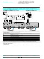
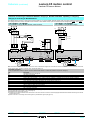
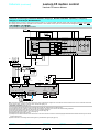
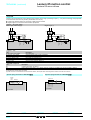
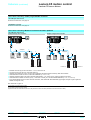
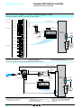
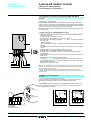
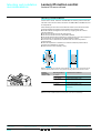
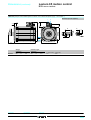
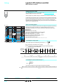
1
Motion control Lexium 05 Catalogue May 06 Flexibility Ingenuity Simplicity b b b Cost effective “optimum” offers that make selection easy for most typical applications b Products that are easy to understand for users, electricians and automation specialists b User-friendly intuitive programming Interchangeable modular functions, to better meet the requirements for extensions b Software and accessories common to multiple product families This international site allows you to access all the Telemecanique products in just 2 clicks via comprehensive range data-sheets, with direct links to: b Complete library: technical documents, catalogs, certificates, FAQs, brochures... b Selection guides from the e-catalog. b Product discovery sites and their Flash animations. You will also find illustrated overviews, news to which you can subscribe, a discussion forum, the list of country contacts... To live automation solutions every day! Auto-adapts to its environment, "plug & play" b Application functions, control, communication and diagnostics embedded in the products b User-friendly operation either directly on the product or remotely Compactness b High functionality in a minimum of space b Freedom in implementation Openness b Compliance with field bus, connection, and software standards b Enabling decentralised or remote surveillance via the web with Transparent Ready products Contents 0 Lexium 05 motion control 1 Lexium 05 offer b Presentation . . . . . . . . . . . . . . . . . . . . . . . . . . . . . . . . . . . . . . . . . . . . . . . page 2 b Servo motor/servo drive combinations . . . . . . . . . . . . . . . . . . . . . . . . . . . page 4 Lexium 05 servo drives b Functions . . . . . . . . . . . . . . . . . . . . . . . . . . . . . . . . . . . . . . . . . . . . . . . . . page 6 b Characteristics. . . . . . . . . . . . . . . . . . . . . . . . . . . . . . . . . . . . . . . . . . . . . page 12 b References v Servo drives. . . . . . . . . . . . . . . . . . . . . . . . . . . . . . . . . . . . . . . . . . . . . page 16 v Separate parts . . . . . . . . . . . . . . . . . . . . . . . . . . . . . . . . . . . . . . . . . . page 17 v CANopen or Profibus DP communication bus . . . . . . . . . . . . . . . . . . page 18 v Modbus serial link . . . . . . . . . . . . . . . . . . . . . . . . . . . . . . . . . . . . . . . . page 19 v Other connecting cables and accessories . . . . . . . . . . . . . . . . . . . . . . page 20 b Options v Braking resistors . . . . . . . . . . . . . . . . . . . . . . . . . . . . . . . . . . . . . . . . . page 25 v Additional EMC input filters . . . . . . . . . . . . . . . . . . . . . . . . . . . . . . . . . page 27 v Line chokes . . . . . . . . . . . . . . . . . . . . . . . . . . . . . . . . . . . . . . . . . . . . . page 28 v Holding brake controller. . . . . . . . . . . . . . . . . . . . . . . . . . . . . . . . . . . . page 29 b Dimensions . . . . . . . . . . . . . . . . . . . . . . . . . . . . . . . . . . . . . . . . . . . . . . . page 30 b Schemes . . . . . . . . . . . . . . . . . . . . . . . . . . . . . . . . . . . . . . . . . . . . . . . . . page 34 b Recommendations for EMC compatibility . . . . . . . . . . . . . . . . . . . . . . . . page 45 b Operation on an IT system . . . . . . . . . . . . . . . . . . . . . . . . . . . . . . . . . . . . page 45 b Motor starters . . . . . . . . . . . . . . . . . . . . . . . . . . . . . . . . . . . . . . . . . . . . . page 46 b Mounting recommendations . . . . . . . . . . . . . . . . . . . . . . . . . . . . . . . . . . page 48 b PowerSuite software workshop . . . . . . . . . . . . . . . . . . . . . . . . . . . . . . . page 52 BSH servo motors b Presentation . . . . . . . . . . . . . . . . . . . . . . . . . . . . . . . . . . . . . . . . . . . . . . page 54 b Characteristics . . . . . . . . . . . . . . . . . . . . . . . . . . . . . . . . . . . . . . . . . . . . . page 56 b References . . . . . . . . . . . . . . . . . . . . . . . . . . . . . . . . . . . . . . . . . . . . . . . page 80 b Dimensions . . . . . . . . . . . . . . . . . . . . . . . . . . . . . . . . . . . . . . . . . . . . . . . page 83 b Options v Integrated holding brake . . . . . . . . . . . . . . . . . . . . . . . . . . . . . . . . . . . page 86 v Integrated encoder . . . . . . . . . . . . . . . . . . . . . . . . . . . . . . . . . . . . . . . page 87 v GBX planetary gearboxes . . . . . . . . . . . . . . . . . . . . . . . . . . . . . . . . . . . page 90 b Servo motor sizing . . . . . . . . . . . . . . . . . . . . . . . . . . . . . . . . . . . . . . . . . . . page 92 Services b Product reference index . . . . . . . . . . . . . . . . . . . . . . . . . . . . . . . . . . . . . page 94 1 Lexium 05 offer 1 Lexium 05 motion control Presentation An extended offer The range of Lexium 05 servo drives that are compatible with BSH servo motors constitutes a compact and dynamic combination for machines across a wide power and supply voltage range: b Lexium 05 servo drive: v 100…120 V single phase, 0.4 to 1.4 kW v 200…240 V single phase, 0.75 to 2.5 kW v 200…240 V three-phase, 0.75 to 3.2 kW v 380…480 V three-phase, 1.4 to 6 kW b BSH servo motor: v Nominal torque: 0.42 to 33.5 Nm v Nominal speed: 1250 to 6000 rpm Lexium 05 servo drive BSH servo motor The Lexium 05 range is enhanced by GBX planetary gearboxes. These are easy to mount, lubricated for life and available in 12 reduction ratios: 3:1 to 40:1. GBX gearboxes are economical, and designed for applications requiring very limited play. Lexium 05 servo drives comply with EN 50178 and IEC/EN 61800-3 international standards and carry UL (USA), cUL (Canada) approvals and e marking. A complete piece of equipment Lexium 05 integrates functions and components that are usually external. This enables users to maintain particularly compact dimensions and makes it easier to integrate the servo drive in control enclosures or machines. Electromagnetic compatibility (EMC) The incorporation of “conducted and radiated” level A EMC filters in LXM 05ppppF1, LXM 05ppppM2 and LXM 05ppppN4 servo drives simplifies installation and provides a very economical means of complying with e marking requirements. LXM 05ppppM3X servo drives are available without an EMC filter. If compliance with EMC standards is required, filters which are available as an option can be installed by the customer. Safety The Lexium 05 servo drive is incorporated in the safety system of installations. It integrates the “Power Removal” safety function which prevents accidental starting of the motor. This function is compliant with machine standard EN 954-1 category 3, standard IEC/EN 61508 SIL2 for electrical installations and draft standard IEC/EN 61800-5-2 for power drives. Braking Lexium 05 servo drives integrate a resistor as standard, which does away with the need to use an external braking resistor in most applications. Dynamic and powerful Thanks to their new winding technology based on salient poles, BSH servo motors are compact and offer a high power density. The low inertia of the rotor and the slight notching effect make it possible to meet demands for accuracy and dynamic performance. Lexium 05: A Telemecanique branded servo drive offer Functions: pages 6 to 11, 54 and 55 2 Characteristics: pages 12 to 15, 56 to 79 This dynamic performance is enhanced by the fast sampling time of the Lexium 05 servo drive control loops: b 62.5 µs for the current loop b 250 µs for the speed loop b 250 µs for the position loop References: pages 16, 80 to 82 Dimensions: pages 30 to 33, 83 to 85 Schemes: pages 34 to 44 1 Lexium 05 offer (continued) 1 Lexium 05 motion control 1 Presentation Control and interfaces The Lexium 05 servo drive can control BSH servo motors in accordance with a large number of control modes: b Point-to-point mode: relative and absolute movements b Electronic gearing mode b Speed control with acceleration/deceleration ramp b Instantaneous speed control b Current control b Manual movement for easy setup Twido CANopen The Lexium 05 servo drive has three control interfaces as standard: b Interface for CANopen, Modbus, or Profibus DP communication network b Two ± 10 V analog reference inputs to give the speed or current reference, and limit the speed or current b One RS 422 (A/B) incremental encoder or pulse/direction input. This input can also be configured as an output to emulate an encoder (ESIM). b These interfaces are supplemented by logic inputs and outputs which can be used as Source (positive logic) or Sink (negative logic) in order to adapt to the outputs of controllers that are available on the market. Simplicity Integration Its high integration level, compact size, the ability to mount it side by side, and its ability to operate at ambient temperatures of 50°C without derating, enable the size of enclosures to be reduced. Low-power servo drives can be mounted on DIN rails. Wiring Spring terminals are used to save time, and avoid periodic checking of tightening torques. Setup Thanks to the SinCos Hiperface® encoder of BSH motors, Lexium 05 automatically receives data from the servo motor. The parameters of the servo motor do not need to be set manually. The “Simply Start” menu, which is available with the PowerSuite software workshop, ensures that the installation operates within a few seconds. The Lexium 05 auto-tuning function and its new algorithm automatically define the optimum gains of the control loops in accordance with the mechanics for different types of movement, including vertical movements. The oscilloscope function of the PowerSuite software workshop is used to display the electrical and mechanical values of the axis. The Fourier series transform (FFT) can be used for fine analysis of the signals from the machine. Dialogue tool Integrated 7-segment display terminal 1 The Lexium 05 servo drive is supplied with an integrated 7-segment display terminal, which is used to set the servo drive parameters, display errors and monitor the system. It is also used to control the servo drive in manual operation. 1 2 Remote LCD terminal 2 ESC ENT stop reset FWO REV RUN Available as an option, it can be mounted on an enclosure door so that the monitoring and adjustment functions and manual operation are always accessible. Its IP 65 protection enables it to be used in difficult environments. PowerSuite 3 3 Functions: pages 6 to 11, 54 and 55 Characteristics: pages 12 to 15, 56 to 79 The PowerSuite software workshop is used to configure, set and debug the Lexium 05 axis in the same way as for all other Telemecanique variable speed drives and starters. It can be used with a direct connection or a Bluetooth® wireless connection. See page 52. References: pages 16, 80 to 82 Dimensions: pages 30 to 33, 83 to 85 Schemes: pages 34 to 44 3 Lexium 05 offer (continued) 1 Lexium 05 motion control 1 BSH servo motor and Lexium 05 servo drive combinations BSH servo motors Lexium 05 single-phase servo drives (1) BSH 0551T 115 V single-phase, with integrated EMC input filter 230 V single-phase, with integrated EMC input filter LXM 05p LXM 05p D10F1 D17F1 D28F1 0.65 kW 1.4 kW M0 nN 0.4 kW 0.5 Nm 3000 rpm 1.4 Nm D17M2 D28M2 0.75 kW 1.2 kW 2.5 kW 6000 rpm 1.4 Nm BSH 0552M 0.9 Nm 1500 rpm 2.3 Nm BSH 0552P 4000 rpm 2.7 Nm 6000 rpm 1500 rpm 1.77 Nm 4.2 Nm 4000 rpm 3.18 Nm 0.9 Nm BSH 0552T 0.9 Nm BSH 0553M 1.3 Nm 3000 rpm BSH 0553P 1.3 Nm BSH 0553T 1.3 Nm 3000 rpm BSH 0701P BSH 0701T 1.4 Nm 1.4 Nm 2500 rpm 1.77 Nm 2.7 Nm 3.31 Nm 6000 rpm 2.42 Nm BSH 0702M 2.1 Nm BSH 0702P 2.2 Nm BSH 0702T 2.12 Nm 2500 rpm BSH 0703M 2.8 Nm 1.4 Nm D10M2 nN 4.14 Nm 3.31 Nm 3000 rpm 5000 rpm 3.2 Nm 1500 rpm 6.8 Nm 3000 rpm 5.37 Nm 6000 rpm 1500 rpm 10 Nm 3.19 Nm 3000 rpm 7.55 Nm 4.14 Nm 6.8 Nm 7.28 Nm 10.3 Nm BSH 0703P 3.1 Nm BSH 0703T 2.8 Nm 2500 rpm 7.38 Nm 6000 rpm 7.38 Nm BSH 1001T BSH 1002P 3.4 Nm 5.8 Nm 2500 rpm 8.5 Nm 4000 rpm 2000 rpm 8.5 Nm 18.3 Nm BSH 1003P 7.8 Nm 2000 rpm 22.79 Nm 1.4 Nm Where: M0 = stall torque nN = maximum nominal speed (see characteristics pages 56 to 78) Peak stall torque that can be supplied by the BSH servo motor and Lexium 05 servo drive combination (1) In the reference, replace p with A for the CANopen version with analog inputs, and with B for the Profibus DP version. Functions: pages 6 to 11, 54 and 55 4 Characteristics: pages 12 to 15, 56 to 79 References: pages 16, 80 to 82 Dimensions: pages 30 to 33, 83 to 85 Schemes: pages 34 to 44 Lexium 05 offer (continued) 1 Lexium 05 motion control 1 BSH servo motor and Lexium 05 servo drive combinations BSH servo motors Lexium 05 three-phase servo drives (1) BSH 0551T 230 V three-phase, without integrated EMC input filter 400/480 V three-phase, with integrated EMC input filter LXM 05p (1) LXM 05p (1) D10M3X D17M3X D42M3X 1.4 kW 3.2 kW M0 nN 0.75 kW 0.5 Nm 6000 rpm 1.4 Nm BSH 0552M 0.9 Nm 1500 rpm 2.3 Nm BSH 0552P 0.9 Nm 4000 rpm 2.7 Nm BSH 0552T 0.9 Nm BSH 0553M 1.3 Nm 6000 rpm 1500 rpm 1.77 Nm 4.2 Nm BSH 0553P 1.3 Nm 4000 rpm 3.18 Nm BSH 0553T 1.3 Nm 6000 rpm BSH 0701M 1.4 Nm BSH 0701P 1.4 Nm 1500 rpm 3000 rpm 3.2 Nm 3.2 Nm BSH 0701T 1.4 Nm 6000 rpm 2.41 Nm BSH 0702M 2.1 Nm 1500 rpm 6.8 Nm BSH 0702P BSH 0702T 2.2 Nm 3000 rpm 2.12 Nm 4500 rpm BSH 0703M 2.8 Nm 1500 rpm BSH 0703P 3.1 Nm 3000 rpm BSH 0703T 2.8 Nm 6000 rpm BSH 1001M 3.4 Nm BSH 1001P 3.3 Nm 2000 rpm BSH 1001T 4000 rpm 3.4 Nm 5.8 Nm 2000 rpm 5.52 Nm 4000 rpm D22N4 D34N4 D57N4 1.4 kW 2.0 kW 3.0 kW 6.0 kW 6000 rpm 2.7 Nm 6000 rpm 3.87 Nm 6000 rpm 7.55 Nm 3000 rpm 10.3 Nm 3.31 Nm 5.37 Nm 3.19 Nm 7.55 Nm 6.8 Nm 10 Nm 7.28 Nm 6000 rpm 8.92 Nm 10.25 Nm 9.45 Nm 2000 rpm 4000 rpm 8.5 Nm 2000 rpm 16 Nm 9.45 Nm 8.5 Nm BSH 1002M 5.5 Nm BSH 1002P BSH 1002T D14N4 nN 12.35 Nm 4000 rpm 15.43 Nm 2000 rpm 27.8 Nm 16 Nm BSH 1003M 7.8 Nm BSH 1003P 8 Nm 2000 rpm 28.3 Nm 4000 rpm 26.97 Nm BSH 1004P 10 Nm 1500 rpm 30.41 Nm 3000 rpm 22.53 Nm 30.41 Nm BSH 1401P 11.1 Nm 2500 rpm 26.2 Nm BSH 1401T 11.1 Nm 2500 rpm 1250 rpm 57.1 Nm 24.77 Nm BSH 1402M 19.5 Nm BSH 1402P BSH 1402T 19.5 Nm 1500 rpm 14.73 Nm 2000 rpm 46.72 Nm 25.04 Nm 3000 rpm 57.42 Nm BSH 1403M 27.8 Nm 1500 rpm BSH 1403P 27.8 Nm 3000 rpm 76.66 Nm 88.17 Nm 57.24 Nm BSH 1404M 33.4 Nm BSH 1404P 33.4 Nm 1500 rpm 3000 rpm 126.45 Nm 60.04 Nm BSH 2051M 36 Nm 1500 rpm 68.3Nm Where: M0 = stall torque nN = maximum nominal speed (see characteristics pages 56 to 78) 1.4 Nm 1.4 Nm Peak stall torque that can be supplied by the BSH servo motor and Lexium 05 servo drive combination (1) In the reference, replace p with A for the CANopen version with analog inputs, and with B for the Profibus DP version. Functions: pages 6 to 11, 54 and 55 Characteristics: pages 12 to 15, 56 to 79 References: pages 16, 80 to 82 Dimensions: pages 30 to 33, 83 to 85 Schemes: pages 34 to 44 5 Functions 1 Lexium 05 motion control 1 Lexium 05 servo drives General overview of Lexium 05 functions The Lexium 05 servo drive integrates a large number of functions, enabling it to be used in a wide range of industrial applications. There are two main function families: b Conventional adjustment functions, such as: v Homing v Manual mode v Auto-tuning of the servo drive/servo motor combination b Operating modes: v Position control: - Point-to-point mode - Electronic gearing mode v Speed control: - Speed control with acceleration/deceleration ramp - Instantaneous speed control v Current control: - Current regulation Two types of operation are possible: b Local mode b Fieldbus mode In local mode: The servo drive parameters are defined via: b The user interface b The remote display terminal b The PowerSuite software Movements are then determined by: b Analog signals (± 10 V) b RS 422 type signals (pulse/direction or A/B signals) In this mode, limit switches and homing switches are not managed by the servodrive. In fieldbus mode: b All the servo drive parameters and those associated with the operating modes can be accessed via: b The fieldbus, in addition to the access via the user interface b The remote display terminal b The PowerSuite software Presentation: pages 2 and 3 6 Characteristics: pages 12 to 15 References: page 16 Dimensions: pages 30 to 33 Schemes: pages 34 to 44 Functions (continued) 1 Lexium 05 motion control 1 Lexium 05 servo drives Adjustment functions Homing Before performing an absolute movement in point-to-point mode, a homing operation must be carried out. Homing consists of associating an axis position with a known mechanical position. This position then becomes the reference position for any subsequent movement of the axis. Homing is carried out by: b Immediately writing the actual position register b Movements up to a reference sensor Homing with search for sensors Four types of homing with movement to sensors are possible: b Homing on - limit switch, “LIMN” b Homing on + limit switch, “LIMP” b Homing on reference contact “REF” with initial movement in negative direction of rotation b Homing on reference contact “REF” with initial movement in positive direction of rotation These homing movements can be performed with or without taking the “Zero marker” pulse into account. LIMN LIMP M 1 2 R- 3 1 Move at search speed HMn 2 Move at output speed HMn_out 3 Clearance at distance HMdis at output speed HMn_out HMdis HMn HMdisout_max HMn_out Homing operating mode: Example with limit switch and clearance from sensor edge Forced homing Forced homing consists of setting the current motor position as the new reference point to which all subsequent positioning data refer. M After power-up, the position value is 0 1 Start movement towards the home point: the servo motor is positioned using a relative movement of 2000 increments 2 Forced homing to value 0 by writing the actual position expressed in user units 3 Initiation of a command to move 2400 increments to the absolute position. The target position is 2400 increments (4400 increments if forced homing had not been performed). M M 1 2000 Inc 0 “2000” 3 2 “0” 0 2400 Inc Forced homing operating mode Homing parameters The homing parameters are transmitted via the fieldbus or using PowerSuite software. Presentation: pages 2 and 3 Characteristics: pages 12 to 15 References: page 16 Dimensions: pages 30 to 33 Schemes: pages 34 to 44 7 Functions (continued) 1 Lexium 05 motion control 1 Lexium 05 servo drives Adjustment functions Manual mode This mode enables an axis to be moved manually. The movement can be carried out over one movement step or continuously, at constant speed. Two speeds of movement are available (slow or fast). Various parameters are used to configure the manual movement. Setpoint value The parameters are transmitted via the fieldbus, the PowerSuite software or the servo drive user interface. 1 0 startMan, Bit0 1 startMan, Bit2 0 n_fastMan Servo motor n_slowMan M Stop 1 2 1 3 4 1 stateMan, Bit14 1: step_Man 0 2: t < time_Man 3: time_Man 4: Continuous movement Adjustment of the machine in manual mode On a rising edge of a “startMan” control bit, a movement step is performed 1 at low or high speed depending on the command on a second bit, “speedMan”. If the “startMan” control bit is maintained active beyond the waiting time “timeMan” example 3 -, the movement is restarted and continues 4 monitored by the operator, until the “startMan” command returns to inactive level. A “stateMan” bit reflects the state - ready/rotating - of the servo motor in manual mode. Auto-tuning of the servo drive/servo motor combination The auto-tuning function integrated in the servo drive enables automatic tuning of the servo control parameters to be performed after the initial configuration. This function is activated via: b The user interface b The remote display terminal b The PowerSuite software This procedure requires the servo motor to be coupled to its mechanism. Additional parameters can be used to limit the amplitude and the direction of the movements performed during the auto-tuning phase. The PowerSuite software also provides screens for carrying out these servo control adjustments conventionally. Presentation: pages 2 and 3 8 Characteristics: pages 12 to 15 References: page 16 Dimensions: pages 30 to 33 Schemes: pages 34 to 44 Functions (continued) 1 Lexium 05 motion control 1 Lexium 05 servo drives Operating modes Operating mode The following table summarizes the various possible operating modes, the control types and the sources of setpoint values. Operating mode Control via fieldbus Setpoint value via local Point-to-point mode Fieldbus or PowerSuite software Electronic gearing mode Pulse/direction signals or A/B signals Speed control with ramp Fieldbus or PowerSuite software Instantaneous speed control Analog input, fieldbus or PowerSuite software Analog input, fieldbus or PowerSuite software Current control Functions available Functions not available Point-to-point mode This mode, also referred to as PTP (Point To Point), is used to move the axis from a position A to a position B. The movement can be absolute: this consists of expressing position B in relation to a home position (the axis must have previously been referenced), or relative: in this case the movement is performed in relation to the current position of the axis (A). The movement is performed according to acceleration, deceleration and speed parameters. Setpoint value The homing parameters are transmitted via the fieldbus or using the PowerSuite software. Software limits Target position Limiting Speed setpoint Limiting Movement generator Actual motor speed Max. speed Acceleration Deceleration Point-to-point mode, absolute and relative Possible applications A motion controller for coordinated axes or a PLC can manage several axes controlled via fieldbus. This mode is often used in material handling, automated inspection, etc. Electronic gearing mode In this mode a master/slave relationship is established between a number of Lexium 05 or between a Lexium 05 and an external master (external A/B encoder, pulse/direction signals). This relationship can be assigned a fixed or variable ratio. The ratio and operating direction parameters can be accessed dynamically via fieldbus. IMAX NMAX GEARratio GearNum GearDenom ESIM pulses AB PD N D Position, speed and current control M PREF M 3~ E IOposInterface GEARdir_enabl RAMP_TAUjerk 9 Functions (continued) 1 Lexium 05 motion control 1 Lexium 05 servo drives Operating modes Electronic gearing mode (continued) Possible applications This mode is used in material handling, conveying and sectional production line applications, as well as in the fields of plastics and fibres. Speed control with acceleration/deceleration ramp In this operating mode, the speed setpoint is applied according to an acceleration/ deceleration ramp that can be adjusted using parameters. The speed setpoint can be modified during the movement. Current limiting is also possible. The position control that is present in the background allows flexible synchronization of two axes that are in speed control mode, and enables position control mode to be entered on the fly. Setpoint value The setpoint value is transmitted via the fieldbus or using the PowerSuite software. Speed profile Actual servo motor speed Speed setpoint Limiting Max. speed Acceleration Deceleration Speed control with acceleration/deceleration ramp operating mode Possible applications This mode is mainly used with infinite axes. Examples include turntable management, printing, labelling applications, etc. Instantaneous speed control In this mode the Lexium 05 servo drive can be used with an analog output motion controller. It is suitable for all other high performance speed control requirements. Setpoint value The setpoint value is transmitted via analog input 1, the fieldbus or the PowerSuite software. Analog input 2 can be used for current or speed limiting. Nref_Scale Analog input 1 (± 10 V) Operating mode Speed control NREF Scaling IMAX NMAX Position, speed and current control Parameters M 3~ Analog input 2 (± 10 V) Scaling Iref_Scale ESIM pulses Current limiting E Activation of limiting Scaling ESIM_Scale RS 422 I/O Mode Instantaneous speed control operating mode Use with analog output motion controller The axis position feedback can be provided to the motion controller by the ESIM (Encoder SIMulation) output on the Lexium 05 servo drive. 10 Functions (continued) 1 Lexium 05 motion control 1 Lexium 05 servo drives Operating modes Instantaneous speed control (continued) Possible applications b Material handling b Packaging b Cutting to length b Winding and unwinding applications Current control Current control is necessary for servo motor torque control. This mode, which can be provided in addition to the other modes, is used in machine phases where torque control is crucial. Setpoint value The setpoint value is transmitted via analog input 1, the fieldbus or the PowerSuite software. Analog input 2 can be used for current or speed limiting. The position and speed of the servo motor are transmitted to the motion controller by the encoder simulation signals (ESIM) of the RS 422 interface. Nref_Scale Analog input 1 (± 10 V) Operating mode Current control IMAX NMAX NREF Scaling Speed and current control Parameters M 3~ Analog input 2 (± 10 V) Scaling Iref_Scale ESIM pulses Speed limiting E Activation of limiting Scaling ESIM_Scale RS 422 I/O Mode Current control operating mode, effects of the adjustable parameters Possible applications b Car assembly applications (tool fixing machine) b Special machines Other functions Other functions for monitoring and setting operating parameters can be activated via: b The “logic” I/O b The fieldbus b The PowerSuite software b The servo drive user interface b v v v v v b b b b b b b b Presentation: pages 2 and 3 Characteristics: pages 12 to 15 Control functions: Status monitoring in movement mode Monitoring of the axis signals Monitoring of the internal signals specific to the servo drive Monitoring switching Monitoring the communication on the fieldbus Entering the various scaling factors Adjusting the movement generator Activation of the STOP signal Triggering the fast stop function (Quick-Stop) Activation of the motor brake via the HBC (Holding Brake Controller) Reversing the direction of rotation of the motor Reading the analog input values Determining the logic of the signals References: page 16 Dimensions: pages 30 to 33 Schemes: pages 34 to 44 11 Characteristics 1 Lexium 05 motion control Lexium 05 servo drives Environmental characteristics Conformity to standards Lexium 05 servo drives have been developed to conform to the strictest international standards and the recommendations relating to electrical industrial control equipment (IEC, EN), including: low voltage, IEC/EN 61800-5-1, IEC/EN 50178, IEC/EN 61800-3 (conducted and radiated EMC immunity and emissions) EMC immunity Conducted and radiated EMC emissions for servo drives IEC/EN 61800-3, environments 1 and 2 IEC/EN 61000-4-2 level 3 IEC/EN 61000-4-3 level 3 IEC/EN 61000-4-4 level 4 IEC/EN 61000-4-5 level 3 LXM LXM LXM LXM IEC/EN 61800-3, environments 1 and 2, categories C2, C3 EN 55011 class A group 2, IEC/EN 61800-3 category C3 With additional EMC filter (1): EN 55011 class A group 1, IEC/EN 61800-3 category C2 05pD10F1…D28F1 05pD10M2...D28M2 05pD14N4...D57N4 05pD10M3X...D42M3X With additional EMC filter (1): EN 55011 class A group 1, IEC/EN 61800-3 category C2 e marking The drives are e marked in accordance with the European low voltage (73/23/EEC and 93/68/EEC) and EMC (89/336/EEC) directives UL (USA), cUL (Canada) Product certification Degree of protection IEC/EN 61800-5-1, IEC/EN 60529 IP 41 on the upper part with protective cover in place IP 20 after removal of the protective cover (see page 48) LXM LXM LXM LXM 05pD10F1…D28F1 05pD10M2...D28M2 05pD10M3X...D42M3X 05pD14N4...D57N4 Vibration resistance LXM LXM LXM LXM 05pD10F1…D28F1 05pD10M2...D28M2 05pD10M3X...D42M3X 05pD14N4...D57N4 According to IEC/EN 60068-2-6: 1.5 mm peak to peak from 3 Hz to 13 Hz 1 gn from 13 Hz to 150 Hz Shock resistance LXM LXM LXM LXM 05pD10F1…D28F1 05pD10M2...D28M2 05pD10M3X...D42M3X 05pD14N4...D57N4 According to IEC/EN 61131 paragraph 6.3.5.2 15 gn for 11 ms conforming to IEC/EN 600028-2-27 Maximum ambient pollution LXM LXM LXM LXM 05pD10F1…D28F1 05pD10M2...D28M2 05pD10M3X...D42M3X 05pD14N4...D57N4 Degree 2 conforming to IEC/EN 61800-5-1 Environmental conditions LXM LXM LXM LXM 05pD10F1…D28F1 05pD10M2...D28M2 05pD10M3X...D42M3X 05pD14N4...D57N4 IEC 60721-3-3 classes 3C1 Relative humidity Ambient air temperature around the device Type of cooling Operation °C Storage °C LXM LXM LXM LXM 05pD10F1 05pD10M2 05pD10M3X 05pD17F1...D57N4 Maximum operating altitude Natural convection Fan m Operating position Maximum permanent angle in relation to the normal vertical mounting position According to IEC 60721-3-3, class 3K3, 5% to 93%, without condensation - 10…+ 50 Temperature derating and limitations: see mounting recommendations page 48 - 25…+ 70 1000 without derating Up to 2000 under the following conditions: b Temperature 40°C max. b Mounting distance between servo drives > 50 mm b Protective film removed 10˚ 10˚ (1) See table on page 27 to check permitted cable lengths. Presentation: pages 2 and 3 12 Functions: pages 6 to 11 References: page 16 Dimensions: pages 30 to 33 Schemes: pages 34 to 44 1 Characteristics (continued) 1 Lexium 05 motion control 1 Lexium 05 servo drives Drive characteristics Switching frequency kHz 4 or 8 depending on rating and associated servo motor. See pages 56 to 78 Voltage V 100 - 15%...120 + 10% single phase for LXM 05pD10F1…D28F1 200 - 15%...240 + 10% single phase for LXM 05pD10M2...D28M2 200 - 15%...240 + 10% three-phase for LXM 05pD10M3X...D42M3X 380 - 15%...480 + 10% three-phase for LXM 05pD14N4...D57N4 Frequency Transient overvoltage Inrush current Leakage current Hz 50 - 5%...60 + 5% Overvoltage category III < 60 < 30 Electrical power characteristics Power supply External 24 V c power supply Input voltage (not provided) (1) Input current (no-load) Ripple A mA V A 24 (-15 / +20%) 1 y 5% Signalling Output voltage 1 red LED: LED lit indicates the presence of servo drive voltage Maximum three-phase voltage equal to line supply voltage Electrical isolation Between power and control sections (inputs, outputs, power supplies) Connection cable characteristics Recommended cable type for mounting in an enclosure Single-strand IEC cable, ambient temperature 45°C, copper 90°C XLPE/EPR or copper 70°C PVC Connection characteristics (terminals for the power supply, the DC bus, and the servo motor) Servo drive terminals Maximum wire size and tightening torque for the power supply, servo motor, braking resistor and DC bus terminals R/L1, S/L2, T/L3 (power supply) PA/+, PBI, PBe (external braking resistor) U/T1, V/T2, W/T3 (servo motor) LXM 05pD10F1 LXM 05pD10M2 LXM 05pD10M3X 2.5 mm2 (AWG 14) 0.8 Nm 2.5 mm2 (AWG 14) 0.8 Nm See characteristics of VW3 M5 10p Rppp cables on page 79 LXM 05pD17F1 LXM 05pD17M2 LXM 05pD17M3X LXM 05pD14N4 6.0 mm2 (AWG 10) 1.2 Nm 6.0 mm2 (AWG 10) 1.2 Nm LXM 05pD28F1 LXM 05pD22N4 LXM 05pD28M2 LXM 05pD42M3X LXM 05pD34N4 6.0 mm2 (AWG 10) 1.2 Nm 6.0 mm2 (AWG 10) 1.2 Nm LXM 05pD57N4 16.0 mm2 (AWG 6) 2.2 Nm 16.0 mm 2 (AWG 6) 2.2 Nm (1) Please consult our specialist catalogue “Interfaces, I/O splitter boxes and power supplies”. Presentation: pages 2 and 3 Functions: pages 6 to 11 References: page 16 Dimensions: pages 30 to 33 Schemes: pages 34 to 44 13 Characteristics (continued) 1 Lexium 05 motion control Lexium 05 servo drives Control signal characteristics Protection Inputs Outputs Against reverse polarity Against short-circuits Presence of an electrical link on the 0 V c Positive or negative (default: positive) Electrical link 24 V c I/O logic Logic inputs Number Power supply Sampling period Debounce filtering Positive logic (Sink) V c ms ms Negative logic (Source) 4 24 0.25 1 State 0 if < 5 V or input not wired, state 1 if > 15 V Logic inputs conforming to standard IEC/EN 61132-2 type 1 State 0 if > 19 V or logic input not wired, state 1 if < 9 V Safety inputs PWRR_A, PWRR_B Type Number Power supply Input filtering Response time Positive logic (Sink) V c ms ms Inputs for the "Power Removal" safety function 2 24 1 y 10 State 0 if < 5 V or input not wired, state 1 if > 15 V Logic inputs conforming to standard IEC/EN 61132-2 type 1 Logic outputs Type Number Output voltage Sampling period Max. breaking current Voltage drop V ms mA V 24 V c logic outputs: positive logic (Source) or negative logic (Sink) 2 y 30, conforming to standard IEC/EN 61131-2 1 50 1 (at 50 mA load) Analog inputs (1) Resolution Range Input resistance Sampling period Absolute error Linearity bit kΩ µs ANA1+/ANA1ANA2+/ANA214 Differential ± 10 V u 10 250 Less than ±1%, less than ±2% over the temperature range Less than ±0.5% Pulse/direction, A/B encoder signals Type Common mode range Input resistance Input frequency Pulse/direction A/B signals V kΩ kHz kHz RS 422 link - 7...+ 12 5 y 200 y 400 kHz RS 422 link y 450 ESIM (encoder emulation) output signals Logic level Output frequency Servo motor encoder feedback signals Voltages Encoder power supply SinCos input signals V V Ω Input resistance + 10 /100 mA 1 VSS with 2.5 V offset 0.5 VSS at 100 kHz 120 Operational safety characteristics Protection Of the machine “Power Removal” (PWR) safety function which forces stopping and/or prevents unintended operation of the servo motor, conforming to EN 954-1 category 3 and draft standard IEC/EN 61800-5-2 Of the system process “Power Removal” (PWR) safety function which forces stopping and/or prevents unintended operation of the servo motor, conforming to IEC/EN 61508 level SIL2 and draft standard IEC/EN 61800-5-2 (1) Only available on LXM 05ADppppp servo drives. Presentation: pages 2 and 3 14 Functions: pages 6 to 11 References: page 16 Dimensions: pages 30 to 33 Schemes: pages 34 to 44 1 Characteristics (continued) 1 Lexium 05 motion control 1 Lexium 05 servo drives Communication port characteristics CANopen protocol, LXM 05ADppppp servo drives Structure Services Connectors Network management Transmission speed Address (Node ID) Polarization PDO PDO modes PDO mapping Number of SDO Emergency Profile Communication monitoring Diagnostics Using LEDs Description file RJ45 (labelled CN4) or spring terminals (labelled CN1) Slave 125 kbps, 250 kbps, 500 kbps or 1 Mbps 1 to 127, configurable via the display terminal or the PowerSuite software workshop Line termination impedances are integrated in the servo drive and are switchable Implicit exchange of PDO (Process Data Objects): b 3 PDO conforming to DSP 402 modes (position control and speed profile modes) b 1 configurable mapping PDO Event-triggered, Time-triggered, Remotely-requested, Sync (cyclic), Sync (acyclic) 1 configurable PDO Explicit exchange of SDO (Service Data Objects): b 2 receive SDO b 2 transmit SDO Yes CiA DSP 402: CANopen “Device Profile Drives and Motion Control” Position control and speed profile modes Node guarding, heartbeat 2 LEDs: “RUN” and “ERROR” on integrated 7-segment display terminal Display of faults Full diagnostics with the PowerSuite software workshop A single eds file for the whole range is supplied on the documentation CD-ROM. This file contains the description of the servo drive parameters Modbus Protocol, LXM 05pDppppp servo drives Structure Connector Physical interface Transmission mode Transmission speed Format Polarization Number of servo drives Address Services Messaging Communication monitoring Diagnostics RJ45 (labelled CN4) 2-wire RS 485 multidrop RTU Configurable via the display terminal or the PowerSuite software workshop: 9600, 19200, or 38400 bps Configurable via the display terminal or the PowerSuite software workshop: b 8 bits, odd parity, 1 stop b 8 bits, even parity, 1 stop b 8 bits, no parity, 1 stop b 8 bits, no parity, 2 stop No polarization impedances These must be provided by the wiring system (for example, in the master) 31 Lexium 05 servo drives maximum 1 to 247, configurable via the display terminal or the PowerSuite software workshop. Read Holding Registers (03) 63 words maximum Write Single Register (06) Write Multiple Registers (16) 61 words maximum Read/Write Multiple Registers (23) 63/59 words maximum Read Device Identification (43) Diagnostics (08) Monitoring function (node guarding) can be activated “Time out” can be set between 0.1 s and 10s Display of faults on integrated 7-segment display terminal Profibus DP protocol, LXM 05BDppppp servo drives Structure Connector Physical interface Transmission speed Address Services Periodic variables Communication monitoring Diagnostics Description file Presentation: pages 2 and 3 Spring terminals (labelled CN1) 2-wire RS 485 multidrop 9600 bps, 19.2 kbps, 45.45 kbps, 93.75 kbps, 187.5 kbps, 500 kbps, 1.5 Mbps, 3 Mbps, 6 Mbps or 12 Mbps 1 to 126, configurable via the integrated 7-segment display terminal or the PowerSuite software workshop PPO type 2 8 PKW bytes 12 Process Data bytes Can be inhibited “Time out” can be set via the Profibus DP network configurator Two LEDs: RUN and ERR Display of faults on integrated 7-segment display terminal Full diagnostics with the PowerSuite software workshop A single gsd file for the whole range is supplied on the documentation CD-ROM. This file does not contain the description of the servo drive parameters Functions: pages 6 to 11 References: page 16 Dimensions: pages 30 to 33 Schemes: pages 34 to 44 15 References 1 Lexium 05 motion control 1 Lexium 05 servo drives Lexium 05 servo drives Output current Continuous (RMS) at 4 kHz at 8 kHz A A LXM 05 pD10F1 LXM 05 pD10M2 LXM 05 pD10M3X Peak (RMS) (2) at 4 kHz at 8 kHz A A Nominal power Line current at 4 kHz kW at U1 (3) A at U2 (3) A Max. Reference (1) prospective line Isc kA Weight kg Single-phase supply voltage: 110…120 V a (3) 50/60 Hz, with integrated EMC filter 4 8 15 3.2 7 13 7 12 20 6 11 20 0.4 0.65 0.85 7.6 11.5 22.6 7 10.5 20.7 1 1 1 LXM 05AD10F1 LXM 05AD17F1 LXM 05AD28F1 1.100 1.400 2.000 Single-phase supply voltage: 200…240 V a (3) 50/60 Hz, with integrated EMC filter LXM LXM LXM LXM 05 pD17F1 05 pD17M2 05 pD17M3X 05 pD14N4 4 8 15 3.2 7 13 7 12 20 6 11 20 0.75 1.2 2.5 8.1 12.7 23 6.7 10.5 19.2 1 1 1 LXM 05AD10M2 LXM 05AD17M2 LXM 05AD28M2 1.100 1.400 2.000 Three-phase supply voltage: 200…240 V a (3) 50/60 Hz, without integrated EMC filter 4 8 17 3.2 7 15 7 12 30 6 11 30 0.75 1.4 3.2 5.2 9 19 4.3 7.5 15.8 5 5 5 LXM 05AD10M3X LXM 05AD17M3X LXM 05AD42M3X 1.100 1.300 1.900 Three-phase supply voltage: 380…480 V a (3) 50/60 Hz, with integrated EMC filter LXM LXM LXM LXM LXM 05 pD28F1 05 pD28M2 05 pD42M3X 05 pD22N4 05 pD34N4 6 9 15 25 5 7 11 20 10 16 24 40 7.5 14 18 30 1.4 2 3 6 4.2 6.3 9.7 17.7 3.3 5 7.7 14 5 5 5 22 LXM 05AD14N4 LXM 05AD22N4 LXM 05AD34N4 LXM 05AD57N4 1.400 2.000 2.000 4.800 (1) References for models with Profibus DP communication: replace LXM 05A with LXM 05B at the beginning of the reference. (2) Maximum value for 3 seconds. (3) Nominal supply voltage, min. U1, max. U2: 110 (U1)…120 V (U2), 200 (U1)…240 V (U2), 380 (U1)…480 V (U2). LXM 05 pD57N4 Presentation: pages 2 and 3 16 Functions: pages 6 to 11 Characteristics: pages 12 to 15 Dimensions: pages 30 to 33 Schemes: pages 34 to 44 References (continued) 1 Lexium 05 motion control 1 Lexium 05 servo drives Separate parts The Lexium 05 servo drive can be connected to a remote display terminal. The remote display terminal can be mounted on the door of an enclosure with IP 65 protection on the front panel. The terminal provides access to the same functions as the integrated display and keypad on the servo drive. It can be used to: b Configure, adjust and control the servo drive remotely b Provide a remote display Description Use Reference Remote display terminal For all Lexium 05. Kit comprising: b Display terminal, 5 m cable equipped with 2 connectors b Seal and screws for IP 65 mounting on an enclosure door VW3 A31101 Weight kg 0.380 Plates for mounting on 5 rail width 35 mm For LXM 05pD10F1/M2/M3X For LXM 05pD17F1/M2/M3X and LXM 05pD14N4 VW3 A11851 VW3 A31852 0.200 0.220 ESC ENT stop reset FWO REV RUN VW3 A31101 Connectors Description Molex connectors (order in multiples of 5) Reference 10-way female connectors for CN5 12-way female connectors for CN2 VW3 M8 212 VW3 M8 213 Weight kg – – Documentation Description Reference Simplified Lexium 05 user's manual and CD-ROM, containing: b A variables user's manual b A Modbus and CANopen user's manual b A Profibus DP user's manual Supplied with the Lexium 05 servo drive – Weight kg – Note: The manuals and quick reference guides for servo drives and servo motors are available on the website: www.telemecanique.com. Presentation: pages 2 and 3 Functions: pages 6 to 11 Characteristics: pages 12 to 15 Dimensions: pages 30 to 33 Schemes: pages 34 to 44 17 References (continued) 1 Lexium 05 motion control 1 Lexium 05 servo drives Twido CANopen machine bus TWD NCO1M The Lexium 05AD servo drive can be connected directly to the CANopen machine bus via spring terminals, or using an RJ45 connector (which supports the CANopen and Modbus protocols). The communication function provides access to the servo drive’s configuration, adjustment, control and monitoring functions. Each servo drive incorporates line terminators that can be disconnected via a switch. 3 4 1 Connection via RJ45 connector (CN4) 2 (1) Connection to Lexium 05AD via RJ45 connector (CN4) Designation Description Item no. 1 Reference IP 20 junction box 2 RJ45 ports Designation Description Item no. 2 2 Reference Item no. Reference 3 TSX CAN KCDF90 T Length m 50 100 300 Item no. 4 4 4 Reference TSX CAN CA 50 TSX CAN CA 100 TSX CAN CA 300 Weight kg 4.930 8.800 24.560 UL certification, e marking Flame retardant (IEC 60332-2) 50 100 300 4 4 4 TSX CAN CB 50 TSX CAN CB 100 TSX CAN CB 300 3.580 7.840 21.870 Cable for harsh environments (4) or mobile installations, e marking Low smoke emission, halogen-free Flame retardant (IEC 60332-1) 50 100 300 4 4 4 TSX CAN CD 50 TSX CAN CD 100 TSX CAN CD 300 3.510 7.770 21.700 Cables for CANopen bus Twido TWD NCO1M 3 2 RJ45 connectors Length m 0.3 1 VW3 CAN TAP2 VW3 CAN CARR03 VW3 CAN CARR1 Weight kg 0.480 Weight kg 0.050 0.500 Connection via terminals (CN1) Designation 4 4 (2) Description CANopen IP 20 90° angled female 9-way SUB-D. SUB-D Switch for line terminator connector (controller side) Weight kg 0.046 Connection to Lexium 05AD via spring terminals (CN1) CANopen cables (3) Description Standard cables, e marking Low smoke emission, halogen-free Flame retardant (IEC 60332-1) TSX CAN KCDF 90T Profibus DP fieldbus TSX CAN CA/CB/CD The Lexium 05BD servo drive can be connected directly to the Profibus DP bus via spring terminals. The communication function provides access to the same functions as those described for CANopen. Premium Cables Designation 3 4 Profibus DP trunk cables 4 18 Item no. 4 4 Reference TSX PBS CA 100 TSX PBS CA 400 (1) RJ45 connector CN4 (2) Spring terminals CN1, terminals 21, 22, 23. (3) For other CANopen bus connection accessories, please consult our catalogue “Machines & installations with CANopen”. (4) Harsh environment: - Resistance to hydrocarbons, industrial oils, detergents, solder splashes - Relative humidity up to 100% - Saline atmosphere - Significant temperature variations - Operating temperature between - 10°C and + 70°C Connection to Lexium 05BD via spring terminals (CN1) Presentation: pages 2 and 3 Length m 100 400 Functions: pages 6 to 11 Characteristics: pages 12 to 15 Dimensions: pages 30 to 33 Schemes: pages 34 to 44 Weight kg – – References (continued) 1 Lexium 05 motion control 1 Lexium 05 servo drives Modbus serial link Twido 1 5 The Lexium 05 servo drive can be connected directly to Modbus using an RJ45 connector (which supports the Modbus and CANopen protocols). The communication function provides access to the servo drive’s configuration, adjustment, control and monitoring functions. 3 2 Connection accessories Description 4 Length m – Item no. – Unit reference TSX SCA 50 Weight kg 0.520 Subscriber socket 2 15-way female SUB-D connectors and 2 screw terminals, RC line terminator To be connected using cable VW3 A8 306 – – TSX SCA 62 0.570 Modbus splitter block 10 RJ45 connectors and 1 screw terminal – 1 LU9 GC3 0.500 – – – – 2 2 – – VW3 A8 306 VW3 A8 306 VW3 A8 306 VW3 A8 306 RC R DRC DR 0.200 0.200 0.200 0.200 Modbus RJ45 T-junction boxes (with integrated cable) 0.3 1 3 3 VW3 A8 306 TF03 VW3 A8 306 TF10 0.190 0.210 Cable for Twido controller serial link 1 mini-DIN connector, 1 RJ45 connector 0.3 1 3 4 4 4 TWD XCA RJ 003 TWD XCA RJ 010 TWD XCA RJ 030 – 0.090 0.160 Length m 1 RJ45 connector and one end 3 with flying leads Item no. – Reference 1 RJ45 connector and 1 15-way 3 male SUB-D connector for TSX SCA 62 – VW3 A8 306 0.150 2 RJ45 connectors 0.3 1 3 5 5 5 VW3 A8 306 R03 VW3 A8 306 R10 VW3 A8 306 R30 0.050 0.050 0.150 100 200 500 – – – TSX CSA 100 TSX CSA 200 TSX CSA 500 2 Junction box 3 screw terminals, RC line terminator To be connected using cable VW3 A8 306 D30 5 Lexium 05AD connection via RJ45 connector (CN4) Modbus line terminator (2) TSX SCA50 For RJ45 R = 120 Ω, C = 1 nf R = 150 Ω For R = 120 Ω, C = 1 nf screw R = 150 Ω terminals Connection cables TSX SCA62 Description Cables for Modbus connection Connectors RS 485 double Supplied without connector shielded twisted pair Modbus cables LU9 GC3 VW3 A8 306 D30 Weight kg 0.150 5.680 10.920 30.000 (1) For connections for other PLCs, please consult our specialist automation product catalogues. (2) Sold in lots of 2. Presentation: pages 2 and 3 Functions: pages 6 to 11 Characteristics: pages 12 to 15 Dimensions: pages 30 to 33 Schemes: pages 34 to 44 19 References (continued) 1 Lexium 05 motion control 1 Lexium 05 servo drives Lexium 05 servo drives Equipped cables for Modicon Premium motion control modules (1) From To Length m Lexium 05 servo drive TSX CAY pp Premium module, encoder input. 0.5 Simulated incremental Cables equipped with a 10-way Molex connector 1.5 encoder feedback interface on the Lexium 05 side (CN5), and a 15-way SUB-D 3 connector on the TSX CAY pp side 5 TSX CFY pp Premium module Reference Lexium 05 servo drive, pulse/direction interface 0.5 Cables equipped with a 10-way Molex connector 1.5 on the Lexium 05 side (CN5), and a 15-way SUB-D 3 connector on the TSX CFY pp side 5 VW3 VW3 VW3 VW3 M8 203 R05 M8 203 R15 M8 203 R30 M8 203 R50 Weight kg 0.020 0.030 0.040 0.050 VW3 VW3 VW3 VW3 M8 204 R05 M8 204 R15 M8 204 R30 M8 204 R50 0.020 0.030 0.040 0.050 Equipped cables for RS 422 control ± 10 V Lexium 05 Lexium 05 Lexium 05 Lexium 05 Lexium 05 External control A B CN5 ESIM Incremental encoder CN5 1 A B CN5 2 A/B in From External control A B P D A/B in CN5 CN5 2 To Lexium 05 servo drive Lexium 05 servo drive, master/slave connection Cables equipped at both ends with a 10-way Molex connector for CN5 External encoder, external control Lexium 05 servo drive (CN5 A/B input) (CN5 pulse/direction input) Lexium 05 servo drive External or other type of control Cables equipped at one end with a 10-way Molex connector for CN5, and flying leads at the other end A/B in 2 ESIM P/D Length m 0.5 1.5 3 5 Item no. 1 1 1 1 Reference VW3 VW3 VW3 VW3 M8 M8 M8 M8 202 R05 202 R15 202 R30 202 R50 Weight kg 0.025 0.035 0.045 0.055 0.5 1.5 3 5 2 2 2 2 VW3 VW3 VW3 VW3 M8 M8 M8 M8 201 R05 201 R15 201 R30 201 R50 0.020 0.030 0.040 0.050 RS 422 interface accessories Designation Description Splitter block for encoder For distributing A/B encoder signals or pulse/ direction signals to five Lexium 05 servo drives. signals Includes a 24 V c / 5 V power supply for (RVA) external encoder Length m – Reference VW3 M3 101 Weight kg 0.700 Cascading cable For cascading two VW3 M3 101 (RVA) splitter blocks 0.5 VW3 M8 211 R05 – RS 422 converter (USIC) For adapting 24 V control signals to RS 422 standard – VW3 M3 102 – Length m 0.5 Reference VW3 M8 209 R05 Weight kg 0.020 1.5 VW3 M8 209 R15 0.030 3 VW3 M8 209 R30 0.040 5 VW3 M8 209 R50 0.050 VW3 M3 102 (USIC) Equipped cables for RS 422 interface From Lexium 05 servo drive (encoder simulator) To VW3 M3 101 (RVA) for ESIM distribution Splitter block VW3 M3 101 Lexium 05 servo drive, input CN5 (RVA) Converter Lexium 05 servo drive, input CN5 VW3 M3 102 (USIC) Cables equipped with a 10-way Molex connector on the Lexium 05 side (CN5), and a 15-way SUB-D connector on the VW3 M3 10 p side (1) For other Modicon Premium connection cables, please consult our catalogue. Note: ESIM (Encoder SIMulation) designates encoder output signals simulated by the servo drives (available on Lexium 05 CN5, configured as output). Presentation: pages 2 and 3 20 Functions: pages 6 to 11 Characteristics: pages 12 to 15 Dimensions: pages 30 to 33 Schemes: pages 34 to 44 References (continued) 1 Lexium 05 motion control 1 Lexium 05 servo drives Other connection cables Description Pulse/direction control cables Siemens S5 IP 247 to Lexium 05 Siemens S5 IP 267 to Lexium 05 Siemens S7 FM 353 to Lexium 05 Cables equipped with a 10-way Molex connector on the Lexium 05 side (CN5), and a 9-way SUB-D connector on the other end Encoder feedback cable Lexium 05 to Siemens S7 FM 354 Cable equipped with a 10-way Molex connector on the Lexium 05 side (CN5), and a 15-way SUB-D connector on the FM 354 side Length m 3 3 3 Reference VW3 M8 205 R30 VW3 M8 206 R30 VW3 M8 207 R30 Weight kg – – – 3 VW3 M8 208 R30 – VW3 M8 VW3 M8 VW3 M8 VW3 M8 – – – – 0.5 PLC to VW3 M3 102 cables For pulse/direction signals (USIC) Cable equipped with a 15-way SUB-D connector on 1.5 the VW3 M3 102 (USIC) side, and flying leads 3 at the other end 5 Presentation: pages 2 and 3 Functions: pages 6 to 11 Characteristics: pages 12 to 15 Dimensions: pages 30 to 33 210 R05 210 R15 210 R30 210 R50 Schemes: pages 34 to 44 21 Lexium 05 motion control Presentation, sizing 1 Lexium 05 servo drives Option: braking resistors Braking resistors Internal braking resistor A braking resistor is built into the servo drive to absorb the braking energy. If the DC bus voltage in the servo drive exceeds a specified value, this braking resistor is activated. The restored energy is converted into heat by the braking resistor. External braking resistor An external braking resistor is necessary for applications in which the servo motor has to be braked frequently and the internal braking resistor cannot dissipate the excess braking energy. If an external braking resistor is used, the internal braking resistor must be deactivated. To do this, the shunt between PA/+ and PBI must be removed and the external braking resistor connected between PA/+ and PBE (see page 41). Two or more external braking resistors can be connected in parallel. The servo drive monitors the power dissipated in the braking resistor. Sizing the braking resistor During braking or deceleration requested by the servo drive, the kinetic energy of the moving load must be absorbed by the servo drive. The energy generated by deceleration charges the capacitors integrated in the servo drive. When the voltage at the capacitor terminals exceeds the permitted threshold, the braking resistor (internal or external) will be activated automatically in order to dissipate this energy. In order to calculate the power to be dissipated by the braking resistor, the user needs a knowledge of the timing diagram giving the servo motor torques and speeds as a function of time in order to identify the curve segments in which the servo drive decelerates the load. Servo motor cycle timing diagram These curves are the same as those used on page 92 for selecting the size of the servo motor. The curve segments to be taken into account, when the servo drive is decelerating, are marked in blue by D i. Servo motor speed ni n3 D1 n2 n1 D3 D2 0 n4 t t1 t2 t3 t4 t5 t6 t7 t8 t9 t10 t11 t12 T cycle M3 M2 M1 0 t M4 M5 Required torque Mi Characteristics: page 24 22 References: page 25 Dimensions: page 31 Schemes: page 41 1 Sizing (continued) 1 Lexium 05 motion control 1 Lexium 05 servo drives Option: braking resistors Sizing the braking resistor (continued) Calculation of the constant deceleration energy To do this, the user must know the total inertia, defined as follows: Jt: Total inertia where: Jt = Jm (servo motor inertia) + Jc (load inertia). For Jm, see pages 56 to 78. The energy Ei of each deceleration segment is defined as follows: 2πn i 2 1 1 2 E i = --- J t ⋅ ω i = --- J t ⋅ ------------ 60 2 2 Which gives the following for the various segments: 2π [ n 3 – n 1 ] 2 1 E 1 = --- J t ⋅ ------------------------------ 2 60 2 2πn 1 E 2 = --- J t ⋅ -------------1 60 2 2πn 2 1 E3 = --- J t ⋅ -------------4 2 60 where Ei is in joules, Jt in kgm2, ω in radians and ni in rpm. Energy absorbed by the internal capacitor The energy absorption capacity of the servo drive Edrive (without using an internal or external braking resistor) is given for each servo drive on page 24. In the remainder of the calculation, only take account of the Di segments, for which the energy Ei is greater than the absorption capacities given in the table opposite. This additional energy EDi must be dissipated in the resistor (internal or external): EDi = Ei - Edrive (in joules). Calculation of the continuous power The continuous power Pc is calculated for each machine cycle: ΣE Di Pc = ------------------Tcycle where Pc is in W, EDi in joules and T cycle in s. Selecting the braking resistor (internal or external) Note: This is a simplified selection method. In extreme applications, for example with vertical axes, this method is inadequate. In this case, please consult your Regional Sales Office. The selection is carried out in two steps: 1 The maximum energy during a braking procedure must be less than the peak energy that can be absorbed by the internal braking resistor: EDi < EPk and the continuous power of the internal braking resistor must in turn not exceed: Pc < PPr. If these conditions are met, the internal braking resistor is adequate. 2 If one of the above conditions is not met, an external braking resistor must be used to satisfy these conditions. The value of the external braking resistor must be between the minimum and maximum values given in the table. Otherwise the servo drive may be subject to disturbance and the load will no longer be braked safely. Presentation: page 22 Characteristics: page 24 References: page 25 Dimensions: page 31 Schemes: page 41 23 Characteristics 1 Lexium 05 motion control 1 Lexium 05 servo drives Option: braking resistors Characteristics LXM 05p Supply voltage Number of phases Load threshold Energy absorption of the internal capacitors Internal Resistance resistor Continuous power Peak energy External Min. resistance resistor Max. resistance Degree of protection Supply voltage Number of phases Load threshold Energy absorption of the internal capacitors Internal Resistance resistor Continuous power Peak energy External Min. resistance resistor Max. resistance Degree of protection Presentation: page 22 24 References: page 25 D10F1 D17F1 115 Single-phase Vc 250 Edrive Joule (Ws) 10.8 16.2 D28F1 V Ω PPr W EPk Joule (Ws) Ω Ω 40 20 500 27 45 IP 65 40 20 27 LXM 05p V D14N4 400 480 Three-phase Vc 780 6 Edrive Joule (Ws) 26 Ω PPr W EPk Joule (Ws) Ω Ω 40 40 1000 60 80 IP 65 Dimensions: page 31 D10M2 D17M2 D28M2 D10M3X D17M3X D42M3X 43 230 Three-phase 430 17.7 26.6 43 27 45 20 60 1600 16 27 40 20 900 50 75 20 60 1600 10 20 230 26 430 17.7 10 60 1000 10 20 40 20 900 50 75 D22N4 400 480 D34N4 400 480 D57N4 400 480 52 12 52 12 104 10 30 60 1600 25 36 26.6 40 20 100 2000 10 21 Schemes: page 41 40 27 45 References 1 Lexium 05 motion control 1 Lexium 05 servo drives Option: braking resistors References External braking resistors Value W 10 VW3 A7 60p Rpp 27 Continuous Peak energy EPk Length of power PPr 115 V 230 V 400 V connection cable Ws Ws Ws W m 400 18800 13300 – 0.75 2 3 100 200 400 72 100 200 400 Presentation: page 22 Characteristics: page 24 Dimensions: page 31 Reference Weight VW3 A7 601 R07 VW3 A7 601 R20 VW3 A7 601 R30 kg 1.420 1.470 1.620 4200 3800 1900 0.75 2 3 9700 7400 4900 0.75 2 3.00 25500 18100 11400 0.75 2 3 VW3 A7 602 R07 VW3 A7 602 R20 VW3 A7 602 R30 VW3 A7 603 R07 VW3 A7 603 R20 VW3 A7 603 R30 VW3 A7 604 R07 VW3 A7 604 R20 VW3 A7 604 R30 0.630 0.780 0.900 0.930 1.080 1.200 1.420 1.470 1.620 5500 3700 3000 VW3 A7 605 R07 VW3 A7 605 R20 VW3 A7 605 R30 VW3 A7 606 R07 VW3 A7 606 R20 VW3 A7 606 R30 VW3 A7 607 R07 VW3 A7 607 R20 VW3 A7 607 R30 0.620 0.750 0.850 0.930 1.080 1.200 1.420 1.470 1.620 0.75 2 3 14600 9600 7600 0.75 2 3 36500 24700 18300 0.75 2 3 Schemes: page 41 25 Presentation 1 Lexium 05 motion control Lexium 05 servo drives Option: additional EMC input filters Integrated EMC input filter Function Lexium 05 LXM 05pDppF1/M2/N4 servo drives have built-in radio interference input filters to comply with the EMC standard for variable speed electrical power drive “products” IEC/EN 61800-3, edition 2, category C3 in environment 2, and to comply with the European directive on EMC (electromagnetic compatibility). L1 M1 3 L2 L3 LXM 05pDppF1 LXM 05pDppM2 LXM 05pDppN4 For Lexium 05 servo drive Maximum servo motor cable length according to EMC category IEC 61800-3, category C3 in environment 2 Switching frequency 4 kHz (default) m Single-phase supply voltage LXM 05AD10F1 LXM 05AD10M2 LXM 05AD17F1 LXM 05AD17M2 LXM 05AD28F1 LXM 05AD28M2 10 10 10 10 10 10 Three-phase supply voltage LXM 05AD14N4 LXM 05AD22N4 LXM 05AD34N4 LXM 05AD57N4 10 10 10 10 Additional EMC input filters Applications L1 L2 Additional EMC filter L3 Lexium 05 M1 3 Additional filters can be used to meet more stringent requirements: these filters are designed to reduce conducted emissions on the line supply below the limits of standard IEC 61800-3 edition 2 categories C2 and C3. These additional filters are mounted either underneath the Lexium 05 servo drives, or to the side of the product. They act as a support for the drives and are attached to them via tapped holes. For servo drives that are not equipped with an EMC filter, reference LXM 05pDppM3X, an additional EMC filter must be provided. Use according to the type of line supply These built-in or additional filters can only be used on TN (neutral connection) and TT (neutral to earth) type supplies. The filters must not be used on IT (impedance or isolated neutral) type supplies. For LXM 05pDppF1/M2/N4 servo drives with integrated filter, the filter must be disconnected using the selector switch on the servo drive (see page 45). Standard IEC/EN 61800-3, appendix D2.1, states that on IT (isolated or impedance earthed neutral) type supplies, filters can adversely affect the operation of the insulation monitors. In addition, the effectiveness of additional filters on this type of line supply depends on the type of impedance between neutral and earth, and therefore cannot be predicted. Note: If a machine is to be installed on an IT supply, one solution is to insert an isolation transformer in order to re-create a TT system on the secondary side. Dimensions: page 32 26 Schemes: page 41 1 Characteristics, references Lexium 05 motion control 1 1 Lexium 05 servo drives Option: additional EMC input filters Characteristics of servo drive/EMC filter mounting Conformity to standards EN 133200 Degree of protection IP 41 on the upper part with protective cover in place IP 20 after removal of the protective cover (see page 48) According to IEC 60721-3-3, class 3K3, 5% to 85%, without condensation or dripping water - 10…+ 50 - 25…+ 70 Relative humidity Ambient temperature around the device Operation Storage Altitude °C °C m 1000 m without derating Up to 2000 m under the following conditions: b Max. temperature 40°C b Mounting distance between servo drives > 50 mm b Removal of the protective cover 10 Hz to 57 Hz: amplitude 0.075 mm 57 Hz to 150 Hz: 1 g 15 gn for 11 ms 120 + 10% 240 + 10% 240 + 10% 480 + 10% Vibration resistance Conforming to IEC 60068-2-6 Shock resistance Conforming to IEC 60068-2-27 Maximum nominal voltage Single-phase 50/60 Hz V Three-phase 50/60 Hz V Application, category: EN 61800-3: 2001-02; IEC 61800-3, Ed. 2 Category C2 in environment 1 Category C3 in environment 2 Description Restricted distribution, for domestic use, sale conditioned by the competence of the user and the distributor on the subject of EMC compatibility Use in industrial premises References Additional EMC input filters 535765 For Lexium 05 servo drive Maximum servo motor cable length according to EMC category, IEC 61800-3 Category C2 Category C3 in environment 2 in environment 2 Switching frequency Switching Switching 4 kHz frequency 4 kHz frequency 8 kHz (default) (default) m m m Reference Weight kg Single-phase supply voltage LXM 05pD10F1 LXM 05pD10M2 LXM 05pD17F1 LXM 05pD17M2 LXM 05pD28F1 LXM 05pD28M2 20 40 100 VW3 A31401 0.600 20 40 100 VW3 A31403 0.775 20 40 100 VW3 A31405 1.130 20 20 40 40 100 100 VW3 A31402 VW3 A31404 0.550 0.900 20 40 100 VW3 A31406 1.350 20 40 100 VW3 A31407 3.150 Three-phase supply voltage VW3 A31402 Dimensions: page 32 LXM 05pD10M3X LXM 05pD17M3X LXM 05pD14N4 LXM 05pD42M3X LXM 05pD22N4 LXM 05pD34N4 LXM 05pD57N4 Schemes: page 41 27 Lexium 05 motion control Presentation, characteristics, references 1 Lexium 05 servo drives Option: line chokes 1 Line chokes A line choke is used to provide improved protection against overvoltages on the line supply and to reduce the current harmonics produced by the servo drive. L1 L2 Line choke M1 3 Lexium 05 L3 The recommended chokes limit the line current. They have been developed in line with standard EN 50178 (VDE 0160 level 1 high energy overvoltages on the line supply). The inductance values are defined for a voltage drop of between 3% and 5% of the nominal line voltage. Values higher than this will cause loss of torque. These chokes must be installed upstream of the servo drive. A number of servo drives can be used on one line choke. The current consumption of all the servo drives must not exceed the nominal current of the line choke (at nominal voltage). Applications The use of line chokes is recommended in particular under the following circumstances: b Close connection of several servo drives in parallel b Line supply with significant disturbance from other equipment (interference, overvoltages) b Line supply with voltage imbalance between phases greater than 1.8% of the nominal voltage b Servo drive supplied by a line with very low impedance (in the vicinity of a power transformer 10 times more powerful than the servo drive rating) b Installation of a large number of servo drives on the same line b Reduction of overloads on the cos ϕ correction capacitors, if the installation includes a power factor correction unit General characteristics Type of line choke Conformity to standards Voltage drop Degree of protection Choke Terminals mH A W Inductance value Nominal current Losses VZ1 L007UM50 VZ1 L018UM20 VW3 A4 551 VW3 A4 552 VW3A4 553 EN 50178 (VDE 0160 level 1 high energy overvoltages on the line supply) Between 3% and 5% of the nominal supply voltage. Values higher than this will cause loss of torque IP 00 IP 20 5 2 10 4 2 7 18 4 10 16 20 30 45 65 75 References Line chokes For LXM 05p servo drive Line current without Line current with choke choke U min. U max. U min. U max. A A A A Single-phase supply voltage: 100…120 V 50/60 Hz (1) D10F1 7.6 7.0 5.9 5.4 D17F1 11.5 10.5 9.7 8.9 D28F1 15.7 14.4 13.3 12.2 Single-phase supply voltage: 200…240 V 50/60 Hz (1) D10M2 8.1 6.7 6.3 5.3 D17M2 12.7 10.5 10.7 8.9 D28M2 23.0 19.2 20.2 16.8 Three-phase supply voltage: 200…240 V 50/60 Hz (1) D10M3X 5.2 4.2 2.7 2.2 D17M3X 9.0 7.5 5.2 4.3 D42M3X 19.0 15.8 12.2 10.2 Three-phase supply voltage: 380…480 V 50/60 Hz (1) D10N4 4.2 3.3 2.2 1.8 D22N4 6.3 5.0 3.4 2.7 D34N4 9.7 7.7 5.8 4.6 D57N4 17.7 14.0 9.8 7.8 VW3 A4 55 p (1) Nominal supply voltage: U min…U max. Dimensions: page 32 28 Schemes: page 41 Reference Weight kg VZ1L007UM50 VZ1L018UM20 0.880 1.990 VZ1L007UM50 VZ1L018UM20 0.880 1.990 VW3 A4 551 VW3 A4 552 VW3 A4 553 1.500 3.000 3.500 VW3 A4 551 1.500 VW3 A4 552 3.500 Presentation, characteristics, references Lexium 05 motion control 1 Lexium 05 servo drives Option: holding brake controller 1 Holding brake controller L1 L2 L3 If a servo motor has a holding brake, it must be given an appropriate control logic (HBC, Holding Brake Controller), which releases the brake when power is supplied to the servo motor and immobilizes the servo motor shaft when it is stationary. c 24 V The holding brake controller amplifies the braking control signal transmitted by the Lexium 05 servo drives, so that the brake is deactivated quickly, then reduces the brake control power so as to decrease the dissipated heat. Lexium 05 HBC Holding brake controller Characteristics Mounting on rail 5 55 Degree of protection IP 20 Supply voltage V 19.2…30 Input current A 0.5 A + brake nominal current V V c 23…25 c 17…19 Maximum current A 1.6 Time before voltage reduction ms 1000 Brake output Voltages Before power reduction After power reduction Note: Electrical isolation between the 24 V power supply, the control input and the brake control output. Reference Holding brake controller Designation Holding brake controller Description Reference c 24 V power supply Max. power 50 W IP 20, for mounting on 55 mm 5 rail VW3 M3 103 Weight kg 0.600 VW3 M3 103 Dimensions: page 32 Schemes: page 41 29 Dimensions 1 Lexium 05 motion control Lexium 05 servo drives Dimensions LXM 05pD10F1, LXM 05pD10M2, LXM 05pD10M3X 5 EMC mounting plate (supplied with servo drive) 60 50 121,5 145 = 140 2xM5 screws 18,5 2xØ5 = 72 51,5 M5 t 4xM4 LXM 05pD17F1, LXM 05pD17M2, LXM 05pD14N4, LXM 05pD17M3X 5 EMC mounting plate (supplied with servo drive) 93 = 105 2xM5 screws 49 = 150 16,5 143 121,5 Ø 67,3 M5 t 4xM4 LXM 05pD28F1, LXM 05pD28M2, LXM 05pD34N4, LXM 05pD42M3X 6,5 EMC mounting plate (supplied with servo drive) 126 = 140 2xM5 screws 49 = 150 20,5 184 157 Ø 88,8 M5 t 4xM4 LXM 05pD57N4 EMC mounting plate (supplied with servo drive) 232 210 5 4xØ5 17 2xM5 screws 160 = 75 = 170 180 134,8 Presentation: pages 2 and 3 30 Functions: pages 6 to 11 Characteristics: pages 12 to 15 4xM4 References: page 16 M5 t Schemes: pages 34 to 44 1 Dimensions (continued) 1 Lexium 05 motion control 1 Options: remote display terminal, plates for mounting on 5 rail and braking resistors Dimensions (continued) Remote display terminal VW3 A31101 55,6 52 79,6 24 Ø36 4xØ3,5 Plates for mounting on 5 rail 143,6 VW3 A11851 37,9 77,5 144 VW3 A31852 40 105 Braking resistors VW3 A7 60p Rpp c = = 60 = b 145 251 257 b1 110 216 216 c 15 15 30 c1 15.5 15.5 – H 98 204 204 = b H b1 4xØ4,6 VW3 A7 602, 605 A7 603, 606 A7 601, 604, 607 c1 Characteristics: page 24 80 References: pages 17 and 25 Schemes: page 41 31 Dimensions (continued) 1 Lexium 05 motion control 1 Options: additional EMC input filters and line chokes Dimensions (continued) Additional EMC input filters Mounting the filter next to the servo drive = Mounting the filter under the servo drive 4xØ b H b 4xØ a = = c G = c a VW3 A31401, A31402 A31403 A31404 A31405 A31406 A31407 a 72 107 107 140 140 180 b 195 195 195 235 235 305 c 37 35 42 35 50 60 G 52 85 85 120 120 140 H 180 180 180 215 215 285 Ø M4 M4 M4 M4 M4 M4 Single-phase line chokes VZ1 L0pppUMp0 b Ø H G c a VZ1 L007UM50 L018UM20 a 60 85 b 100 120 c 95 105 G 50 70 H 60 70 Ø 4x9 5 x 11 VW3 A4 551 A4 552 A4 553 a 100 130 130 b 135 155 155 c 55 85 85 c1 60 90 90 G 40 60 60 G1 60 80.5 80.5 Three-phase line chokes b VW3 A4 55p 8xØ H G c G1 c1 a Presentation: pages 26 and 28 32 References: pages 27 and 28 Schemes: page 41 H 42 62 62 Ø 6x9 6 x 12 6 x 12 Dimensions (continued) Lexium 05 motion control 1 1 Options: splitter block, USIC and holding brake controller Dimensions (continued) Splitter block 77 VW3 M3 101 15 12 135 25 RS 422 converter (USIC) 77 VW3 M3 102 15 12 67,5 38 Holding brake controller 99 VW3 M3 103 114,5 References: pages 20 and 29 22,5 Schemes: page 41 33 Schemes 1 Lexium 05 motion control 1 Lexium 05 servo drives Safety requirements “Power Removal” safety function The Lexium 05 servo drive integrates the “Power Removal” safety function which prevents unintended operation of the servo motor. The servo motor no longer produces any torque. This safety function: b Complies with the standard for safety of machinery EN 954-1, category 3 b Complies with the standard for functional safety IEC/EN 61508, SIL2 capability (safety control-signalling applied to processes and systems) The SIL (Safety Integrity Level) capability depends on the connection diagram for the servo drive and for the safety function. Failure to observe the setup recommendations could inhibit the SIL capability of the “Power Removal” safety function. b Complies with draft product standard IEC/EN 61800-5-2 for both stop functions: v Safe Torque Off (“STO”) v Safe Stop 1 (“SS1”) The “Power Removal” safety function has a redundant electronic architecture (1) which is monitored continuously by a diagnostics function. This level SIL2 and category 3 safety function is certified as conforming to these standards by the TUV certification body in the context of a voluntary certification program. Categories relating to safety according to EN 954-1 Category B 1 Basic safety principle Control system requirements Selection of components Control according to good that conform to relevant engineering practice standards Selecting components Use of tried and tested and safety principles components and proven safety principles 2 Selecting components and safety principles 3 Structure of the safety circuits 4 Structure of the safety circuits Behaviour in the event of a fault Possible loss of the safety function Cyclic testing. The intervals between tests must be appropriate to both the machine and its application A single fault must not result in loss of the safety function. The fault must be detected if this is reasonably possible A single fault must not result in loss of the safety function. The fault must be detected when or before the safety function is next invoked. An accumulation of faults must not result in loss of the safety function. Possible loss of the safety function with a lower probability than in B Fault detected at each test Safety function ensured, except in the event of an accumulation of faults Safety function always ensured The machinery manufacturer is responsible for selecting the safety category. The category depends on the level of risk factors given in standard EN 954-1. Safety Integrity Levels (SIL) according to standard IEC/EN 61508 SIL1 according to standard IEC/EN 61508 is comparable to category 1 according to EN 954-1 (SIL1: mean probability of undetected hazardous failure per hour between 10-5 and 10-6). SIL2 according to standard IEC/EN 61508 is comparable to category 3 according to EN 954-1 (SIL2: mean probability of undetected hazardous failure per hour between 10-6 and 10-7). (1) Redundant: Consists of mitigating the effects of the failure of one component by means of the correct operation of another, assuming that faults do not occur simultaneously on both. Presentation: pages 2 and 3 34 Functions: pages 6 to 11, 54 and 55 Characteristics: pages 12 to 15, 56 to 79 References: pages 16, 80 to 82 Dimensions: pages 30 to 33, 83 to 85 Schemes (continued) 1 Lexium 05 motion control 1 Lexium 05 servo drives Safety requirements “Power Removal” safety function considerations The “Power Removal” safety function cannot be considered as a means of electrical disconnection of the servo motor (no electrical isolation); if necessary, a Vario switch disconnector must be used. The “Power Removal” safety function is not designed to compensate for any malfunction in the servo drive process control or application functions. The output signals available on the servo drive must not be considered as safety-related signals (e.g. “Power Removal” active); these are Preventa-type safety module outputs which must be integrated into a safety control-signalling circuit. The schemes on the following pages take into account conformity with standard IEC/EN 60204-1 which defines three stopping categories: b Category 0: Stopping by immediate removal of the power from the actuators (e.g. uncontrolled stop) b Category 1: Controlled stop maintaining the power on the actuators until the machine stops, then removal of the power when the actuators stop when the machine stops b Category 2: Controlled stop maintaining the power on the actuators Connection diagrams and applications Conformity to category 1 of standard EN 954-1 and level SIL1 according to standard IEC/EN 61508 Use of the connection diagrams on page 36, which use a line contactor or a Vario switch disconnector between the servo drive and the servo motor: In this case, the “Power Removal” safety function is not used and the servo motor stops in accordance with category 0 of standard IEC/EN 60204-1. Conformity to category 3 of standard EN 954-1 and level SIL2 according to standard IEC/EN 61508 The connection diagrams use the “Power Removal” safety function of the Lexium 05 servo drive combined with a Preventa safety module to monitor the emergency stop circuits. Machines with short freewheel stopping times (low inertia or high resistive torque, see page 37). When the activation command is given on the PWRR_A and PWRR_B inputs with the controlled servo motor, the servo motor power supply is cut immediately and the servo motor stops according to category 0 of standard IEC/EN 60204-1. Restarting is not permitted even when the activation command is given after the servo motor has come to a complete stop. This safe stop is maintained as long as the PWRR_A and PWRR_B inputs remain activated. This diagram must also be used for hoisting applications. On a “Power Removal” command, the servo drive requires the brake to be engaged, but a Preventa safety module contact must be inserted in series in the brake control circuit to engage it safely when a request is made to activate the “Power Removal” safety function. Machines with long freewheel stopping times (high inertia or low resistive torque, see pages 38 and 39). When the activation command is given, deceleration of the servo motor controlled by the servo drive is first requested, then, following a time delay controlled by an XPS AV (Preventa-type) fault relay which corresponds to the deceleration time, the “Power Removal” safety function is activated by the PWRR_A and PWRR_B inputs. The servo motor stops according to category 1 of standard IEC/EN 60204-1 (“SS1”). Note: Periodic test: The “Power Removal” safety input must be activated at least once a year for preventive maintenance purposes. The servo drive must be switched off before preventive maintenance is carried out, and then powered up again. If the power supply to the servo motor is not switched off during testing, safety integrity is no longer assured for the “Power Removal” safety function. The servo drive must therefore be replaced to ensure the operational safety of the machine or the system process. Presentation: pages 2 and 3 Functions: pages 6 to 11, 54 and 55 Characteristics: pages 12 to 15, 56 to 79 References: pages 16, 80 to 82 Dimensions: pages 30 to 33, 83 to 85 35 Schemes (continued) 1 Lexium 05 motion control 1 Lexium 05 servo drives Schemes conforming to standards EN 954-1 category 1, IEC/EN 61508 SIL1 capability, in stopping category 0 according to IEC/EN 60204-1 1 3 5 2 4 6 Q1 5 Power section for single phase power supply 3 LXM 05pDppF1, LXM 05pDppM2 Three phase power supply with upstream breaking via contactor 1 LXM 05pDppM3X, LXM 05pDppN4 1 Q2 2 4 5 5 To 3/Q2 (1) KM1 13 14 P1 L1 12 6 7 1 CN2 8 (4) 6 1 CN5 W / T3 V / T2 U / T1 S / L2 / N R / L1 PWRR_B + 24 VDC HALT Interface position 10 5 A1 PC/- MOD/CAN CN4 CN1 PA/+ Motor Encoder PWRR_A 31 32 33 34 35 36 37 38 39 CN3 0VDC 0VDC + 24 VDC + 24 VDC W / T3 V / T2 T / L3 U / T1 PC/- S / L2 PBE PBI R / L1 44 43 42 41 PA/+ (3) (2) ACTIVE1_OUT A1 - NO_FAULT_OUT + PBI L1 4 2 6 KM1 PBE 3 4 KM1 A2 To 1/Q2 1 Q4 2 KM1 2 A1 6 Q2 1 S1 3 3 S2 1 Q3 2 T1 1 6 4 2 Q1 Motor Encoder 12 6 7 1 CN2 1 (5) (6) M1 M1 Note: All terminals are located at the bottom of the servo drive. Fit interference suppressors to all inductive circuits near the servo drive or connected on the same circuit, such as relays, contactors, solenoid valves, fluorescent lighting, etc. Compatible components (for a complete list of references, please consult our “Motor starter solutions - Control and protection components" catalogue). Ref. Description A1 Lexium 05 servo drive, see page 16 KM1 Line contactor, see motor starters on pages 46 and 47 L1 Line choke, see page 28 M1 BSH servo motor, see pages 80 and 81 P1 Phaseo (SELV) power supply c 24 V, please consult our “Interfaces, I/O splitter boxes and power supplies” catalogue Q1 Circuit-breaker, see motor starters on pages 46 and 47 Q2 GV2 L magnetic circuit-breaker rated at twice the nominal primary current of T1 Q3, Q4 GB2 CB05 thermal magnetic circuit-breaker S1, S2 XB4 B or XB5 A “Start” and “Emergency stop” pushbuttons T1 220 V secondary transformer (1) Insert (in series) a contact of the relay controlled by the “NO_FAULT_OUT” (31) logic output: On a servo drive fault, KM1 (line contactor) opens. (2) Specific spring terminals according to the type of servo drive (see page 42) (3) 4 logic inputs and 2 logic outputs c 24 V (see page 42) (4) External braking resistor (see page 25) (5) CANopen bus or Modbus serial link on RJ45 connector. Can also be used to connect a PC terminal (equipped with PowerSuite software workshop) or the remote terminal VW3 A31101. (6) Molex connector for connecting A/B encoder signals or pulse/direction signals (see page 44) Presentation: pages 2 and 3 36 Functions: pages 6 to 11, 54 and 55 Characteristics: pages 12 to 15, 56 to 79 References: pages 16, 80 to 82 Dimensions: pages 30 to 33, 83 to 85 Schemes (continued) 1 Lexium 05 motion control 1 Lexium 05 servo drives Schemes conforming to standards EN 954-1 category 3, IEC/EN 61508 SIL2 capability, in stopping category 0 according to IEC/EN 60204-1 The diagram below is shown in local control mode via logic I/O. In communication network control mode, the inputs marked 34 and 35 on the CN1 spring terminals must be controlled via the network. In this network mode, inputs 34 and 35 have the assignments “LIMN” and “LIMP”. LXM 05pDppM3X, LXM 05pDppN4 LXM 05pDppF1, LXM 05pDppM2 Power section for single phase power supply 1 3 5 2 4 6 5 3 Q1 1 Three phase power supply, low inertia machine, vertical movement 6 4 2 Q1 1 Q2 2 3 T1 4 5 To 1/Q2 6 1 Q3 2 Q2 To 3/Q2 S1 S2 P1 S3 (1) 12 6 7 1 CN2 8 (3) 10 5 6 1 CN5 W / T3 V / T2 U / T1 PC/- PBE R / L1 Interface position S / L2 / N PWRR_B + 24 VDC HALT PWRR_A ENABLE A1 PBI MOD/CAN CN4 CN1 PA/+ Motor Encoder REF 31 32 33 34 35 36 37 38 39 CN3 0VDC 0VDC + 24 VDC + 24 VDC W / T3 V / T2 T / L3 U / T1 PC/- S / L2 PBE PBI PA/+ R / L1 44 43 42 41 L1 (2) FAULT_RESET A1 - NO_FAULT_OUT + ACTIVE1_OUT L1 Motor Encoder 12 6 7 1 CN2 1 (3) (4) (5) M1 M1 Note: All terminals are located at the bottom of the servo drive. Fit interference suppressors to all inductive circuits near the servo drive or connected on the same circuit, such as relays, contactors, solenoid valves, fluorescent lighting, etc. Compatible components (for the complete list of references, please consult our “Motor starter solutions - Control and protection components" catalogue). Ref. Description A1 Lexium 05 servo drive, see page 16 L1 Line choke, see page 28 M1 BSH servo motor, see pages 80 and 81 P1 Phaseo (SELV) power supply c 24 V, please consult our “Interfaces, I/O splitter boxes and power supplies” catalogue Q1 Circuit-breaker, see motor starters on pages 46 and 47 Q2 GV2 L magnetic circuit-breaker rated at twice the nominal primary current of T1 Q3 GB2 CB05 thermal magnetic circuit-breaker S1 XB4 B or XB5 A “Emergency stop” dual contact pushbutton S2 XB4 B or XB5 A “Enable” stay-put pushbutton S3 XB4 B or XB5 A “Reset” pushbutton T1 220 V secondary transformer (1) Specific spring terminals according to the type of servo drive (see page 42) (2) 1 logic input and 2 logic outputs c 24 V (see page 42) (3) External braking resistor (see page 25) (4) CANopen bus or Modbus serial link on RJ45 connector. Can also be used to connect a PC terminal (equipped with PowerSuite software workshop) or the remote terminal VW3 A31101. (5) Molex connector for connecting A/B encoder signals or pulse/direction signals (see page 44) Presentation: pages 2 and 3 Functions: pages 6 to 11, 54 and 55 Characteristics: pages 12 to 15, 56 to 79 References: pages 16, 80 to 82 Dimensions: pages 30 to 33, 83 to 85 37 Schemes (continued) Lexium 05 motion control 1 1 Lexium 05 servo drives Schemes conforming to standards EN 954-1 category 3, IEC/EN 61508 SIL2 capability, in stopping category 0 according to IEC/EN 60204-1 (continued) The diagram below is shown in local control mode via logic I/O. In communication network control mode, the inputs marked 34 and 35 on the CN1 spring terminals must be controlled via the network. In this network mode, inputs 34 and 35 have the assignments “LIMN” and “LIMP”. LXM 05pDppM3X, LXM 05pDppN4 LXM 05pDppF1, LXM 05pDppM2 Three phase power supply, low inertia machine, vertical movement F1 S2 (1) + 24 V 0V ESC A1 Y1 33 3 5 6 K2 K1 Q1 K2 PE 14 24 34 Y44 (3) T1 4 5 Y43 1 6 4 2 23 K1 48 V, 115 V, 230 V A2 3 13 – T 1 Q2 2 Y2 + 5 3 1 XPS AC 4 A2 2 S1 (2) To 1/Q2 6 1 Q3 2 Q2 (4) To 3/Q2 P1 (5) (6) 12 6 7 1 CN2 8 (7) 10 5 6 1 CN5 W / T3 V / T2 U / T1 PC/- S / L2 / N R / L1 Interface position PBE PWRR_B + 24 VDC HALT PWRR_A A1 PBI MOD/CAN CN4 CN1 PA/+ Motor Encoder ENABLE 31 32 33 34 35 36 37 38 39 CN3 0VDC 0VDC + 24 VDC + 24 VDC W / T3 V / T2 T / L3 U / T1 PC/- S / L2 PBE PBI R / L1 44 43 42 41 PA/+ L1 0V + 24 V REF A1 - FAULT_RESET + NO_FAULT_OUT L1 ACTIVE1_OUT Q1 Power section for single phase power supply Motor Encoder 12 6 7 1 CN2 1 (7) (8) M1 (9) M1 Note: All terminals are located at the bottom of the servo drive. Fit interference suppressors to all inductive circuits near the servo drive or connected on the same circuit, such as relays, contactors, solenoid valves, fluorescent lighting, etc. Compatible components (for a complete list of references, please consult our “Motor starter solutions. Control and protection components” and “Safety solutions using Preventa” catalogues). Ref. Description A1 Lexium 05 servo drive, see page 16 A2 Preventa XPS AC safety module for monitoring emergency stops and switches. The XPS AC safety module can manage the “Power Removal” function of several servo drives on the same machine. F1 Fuse L1 Line choke, see page 28 M1 BSH servo motor, see pages 80 and 81 P1 Phaseo (SELV) power supply c 24 V, please consult our “Interfaces, I/O splitter boxes and power supplies” catalogue Q1 Circuit-breaker, see motor starters on pages 46 and 47 Q2 GV2 L magnetic circuit-breaker rated at twice the nominal primary current of T1 Q3 GB2 CB05 thermal magnetic circuit-breaker S1 XB4 B or XB5 A “Emergency stop” pushbutton with 2 contacts S2 XB4 B or XB5 A spring return pushbutton T1 220 V secondary transformer (1) S2: Resets the XPS AC module on power-up or after an emergency stop. ESC can be used to set external starting conditions. (2) S1: Requests uncontrolled stopping of the movement and activates the “Power Removal” safety function. (3) The logic output can be used to indicate that the machine is in a safe stop state. (4) To “Power Removal” safety function of an Altivar 71 variable speed servo drive (for example). (5) Specific spring terminals according to the type of servo drive (see page 42) (6) 4 logic inputs and 2 logic outputs c 24 V (see page 42) (7) External braking resistor (see page 25) (8) CANopen bus or Modbus serial link on RJ45 connector. Can also be used to connect a PC terminal (equipped with PowerSuite software workshop) or the remote terminal VW3 A31101. (9) Molex connector for connecting A/B encoder signals or pulse/direction signals (see page 44) 38 Schemes (continued) Lexium 05 motion control 1 1 Lexium 05 servo drives Schemes conforming to standards EN 954-1 category 3, IEC/EN 61508 SIL2 capability, in stopping category 1 according to IEC/EN 60204-1 The diagram below is shown in local control mode via logic I/O. In communication network control mode, the inputs marked 34 and 35 on the CN1 spring terminals must be controlled via the network. In this network mode, inputs 34 and 35 have the assignments “LIMN” and “LIMP”. LXM 05pDppM3X, LXM 05pDppN4 Three phase power supply, high inertia machine + 24 V A2 A1 S13 S11 S31 S32 S12 S14 03 13 23 37 47 57 Y40 04 14 24 38 48 58 Y+ Y64 Y74 Y84 K3/K4 (1) K1/K2 S1 12 11 F1 K1 K3 K2 K4 XPS AV A2 Y39 S21 S22 S34 (3) 22 S1 14 S2 (2) 5 3 Q1 1 13 21 S33 ESC 6 4 2 0V 1 Q2 2 3 T1 4 5 6 1 Q3 2 Q2 S3 P1 L1 (4) (5) Motor Encoder 12 6 7 1 CN2 PWRR_B CN1 + 24 VDC HALT PWRR_A ENABLE REF MOD/CAN CN4 8 (6) FAULT_RESET 31 32 33 34 35 36 37 38 39 CN3 0VDC 0VDC + 24 VDC + 24 VDC W / T3 V / T2 T / L3 U / T1 PC/- S / L2 PBE PBI R / L1 44 43 42 41 PA/+ S4 0V + 24 V ACTIVE1_OUT A1 - NO_FAULT_OUT + Interface position 10 5 6 1 CN5 1 (7) (8) M1 Note: All terminals are located at the bottom of the servo drive. Fit interference suppressors to all inductive circuits near the servo drive or connected on the same circuit, such as relays, contactors, solenoid valves, fluorescent lighting, etc. Compatible components (see page 40) (1) S1: Requests controlled stopping of the movement and activates the “Power Removal” safety function. (2) S2: Resets the XPS AT module on power-up or after an emergency stop. ESC can be used to set external starting conditions. (3) Time-delayed opening safety outputs, 300 seconds max. (stopping category 1) (4) Specific spring terminals according to the type of servo drive(see page 42) (5) 1 logic input and 2 logic outputs c 24 V (see page 42) (6) External braking resistor (see page 25) (7) CANopen bus or Modbus serial link on RJ45 connector. Can also be used to connect a PC terminal (equipped with PowerSuite software workshop) or the remote terminal VW3 A31101. (8) Molex connector for connecting A/B encoder signals or pulse/direction signals (see page 44) Presentation: pages 2 and 3 Functions: pages 6 to 11, 54 and 55 Characteristics: pages 12 to 15, 56 to 79 References: pages 16, 80 to 82 Dimensions: pages 30 to 33, 83 to 85 39 Schemes (continued) 1 Lexium 05 motion control Lexium 05 servo drives Schemes conforming to standards EN 954-1 category 3, IEC/EN 61508 SIL2 capability, in stopping category 1 according to IEC/EN 60204-1 (continued) LXM 05pDppM3X, LXM 05pDppN4 Three phase power supply, high inertia machine (continued) Compatible components (for a complete list of references, please consult our “Motor starter solutions. Control and protection components” and “Safety solutions using Preventa” catalogues). Ref. Description A1 Lexium 05 servo drive, see page 16 A2 (1) Preventa XPS AV safety module for monitoring emergency stops and switches. One safety module can manage the “Power Removal” function for several drives on the same machine, but the time delay must be adjusted on the servo drive controlling the servo motor that requires the longest stopping time. F1 Fuse L1 Line choke, see page 28 M1 Lexium BSH AC servo motor, see pages 80 and 81 P1 Phaseo (SELV) power supply c 24 V, please consult our “Interfaces, I/O splitter boxes and power supplies” catalogue Q1 Circuit-breaker, see motor starters on pages 46 and 47 Q2 GV2 L magnetic circuit-breaker rated at twice the nominal primary current of T1 Q3 GB2 CB05 thermal magnetic circuit-breaker S1 XB4 B or XB5 A “Emergency stop” dual contact pushbutton S2 XB4 B or XB5 A “Start” pushbutton S3 XB4 B or XB5 A “Enable” stay-put pushbutton S4 XB4 B or XB5 A “Reset” pushbutton T1 220 V secondary transformer (1) For stopping times requiring more than 30 seconds in category 1, use a Preventa XPS AV safety module which can provide a maximum time delay of 300 seconds. LXM 05pDppF1, LXM 05pDppM2 1 3 5 2 4 6 Power section for single phase power supply, high inertia machine Q1 To 1/Q2 3 1 To 3/Q2 4 2 KM1 L1 W / T3 V / T2 U / T1 PC/- PBE R / L1 PBI PA/+ S / L2 / N A1 Motor Encoder 12 6 7 1 CN2 (1) M1 Note: All terminals are located at the bottom of the servo drive. Fit interference suppressors to all inductive circuits near the servo drive or connected in the same circuit, such as relays, contactors, solenoid valves, fluorescent lighting, etc. Compatible components (for a complete list of references, please consult our “Motor starter solutions. Control and protection components” and “Safety solutions using Preventa” catalogues). Ref. Description A1 Lexium 05 servo drive, see page 16 L1 Line choke, see page 28 M1 Lexium BSH AC servo motor, see pages 80 and 81 Q1 Circuit-breaker, see motor starters on pages 46 and 47 Q2 GV2 L magnetic circuit-breaker rated at twice the nominal primary current of T1 (1) External braking resistor (see page 25) Presentation: pages 2 and 3 40 Functions: pages 6 to 11, 54 and 55 Characteristics: pages 12 to 15, 56 to 79 References: pages 16, 80 to 82 Dimensions: pages 30 to 33, 83 to 85 1 Schemes (continued) 1 Lexium 05 motion control 1 Lexium 05 servo drives Braking resistor Holding brake controller Internal resistor External resistor P1 CN1 A2 14 13 12 11 REF ACTIVE1_OUT 0VDC 0VDC + 24 VDC + 24 VDC 31 32 33 CN3 W / T3 V / T2 U / T1 W / T3 V / T2 U / T1 PC/- R / L1 S / L2 / N PBE PBI PA/+ W / T3 V / T2 U / T1 PC/- 44 43 42 41 NO_FAULT_OUT A1 S / L2 / N PBE PBI PA/+ R / L1 A1 PC/- A1 HBC 32 34 R1 M1 Compatible components Ref. A1 A2 M1 P1 R1 Description Lexium 05 servo drive, see page 16 Holding brake controller VW3 M3103, see page 29 BSH servo motor with holding brake, see pages 80 and 81 Phaseo (SELV) power supply c 24 V, please consult our “Interfaces, I/O splitter boxes and power supplies” catalogue External braking resistor VW3 A7 60pRpp, see page 25 Line chokes Three phase power supply VW3 A4 552/553/554 Single phase power supply VZ1L0ppUMp0 LXM 05pDppM3X/N4 Compatible components Ref. L1 L2 S/L2/N E1 R/L1 E3 T/L3 S1 L2 S3 E2 S/L2 S2 E1 R/L1 L1 S1 2 LXM 05pDppF1/M2 Description Three phase line choke VW3 A4 552/553/554, see page 28 Single phase line choke VZ1L0ppUMp0, see page 28 Additional EMC input filters VW3 A3140p Three phase power supply Single phase power supply 2 L'1 S/L2/N L2 L'2 R/L1 L'3 T/L3 LXM 05pDppM3X/N4 L1 F2 L3 L'2 S/L2 L2 L'1 R/L1 L1 F1 LXM 05pDppF1/M2 Compatible components Ref. Description F1 Three phase additional EMC input filter VW3 A31402/404/406/407, see page 27 F2 Single phase additional EMC input filter VW3 A31401/403/405, see page 27 Note: The additional EMC input filters are connected as close as possible to the servo drive, directly upstream of the drive. 41 Schemes (continued) 1 Lexium 05 motion control Lexium 05 servo drives Logic I/O The servo drive parameters are used to adapt the logic operation of the 4 logic inputs/2 logic outputs (c 24 V) to the technology of the peripherals connected to the servo drive I/O (sensors, preactuators, PLC I/O, etc): b Positive logic (default setting) for connection to PNP transistor sensors b Negative logic for connection to NPN transistor peripherals External c 24 V power supply Positive logic (default setting) (1) Negative logic (2) P1 P1 - + + - - - Logic I/O c 24 V Ref. 31 “NO_FAULT_OUT” output 32 “ACTIVE1_OUT” output 33 “REF” input 34 “FAULT_RESET” input 35 “ENABLE” input 36 “HALT” input PWRR_B CN1 + 24 VDC HALT PWRR_A ENABLE FAULT_RESET REF 31 32 33 34 35 36 37 38 39 NO_FAULT_OUT CN3 0VDC 0VDC 44 43 42 41 + 24 VDC A1 + 24 VDC PWRR_B CN1 + 24 VDC HALT PWRR_A ENABLE REF FAULT_RESET NO_FAULT_OUT ACTIVE1_OUT 31 32 33 34 35 36 37 38 39 CN3 0VDC 0VDC + 24 VDC 44 43 42 41 + 24 VDC A1 + ACTIVE1_OUT + Description Servo drive fault Control of holding brake controller VW3 M3103 Not used (3) Reset, fault acknowledgement (3) Enable servo drive power bridge (3) Stop servo drive (stopping category 1) Compatible components Ref. Description A1 Lexium 05 servo drive, see page 16 P1 Phaseo (SELV) power supply c 24 V, please consult our “Interfaces, I/O splitter boxes and power supplies” catalogue (1) Positive logic: Sink input, Source output (2) Negative logic: Source input, Sink output (3) If the servo drive is controlled via the communication network, these inputs have other assignments. Please consult the user's manual. Specific spring terminals for LXM 05ADppppp 2 analog inputs ± 10 V CANopen 42 RxD/TxD-P-Out RxD/TxD-N-Out CN1 LXM 05BDppppp LXM 05ADppppp Presentation: pages 2 and 3 RxD/TxD-P-In 21 22 23 24 CN1 RxD/TxD-N-In CAN_L Profibus DP CAN_H CAN_0V ANA2– ANA2+ ANA– ANA1+ 11 12 13 14 21 22 23 Specific spring terminals for LXM 05BDppppp Functions: pages 6 to 11, 54 and 55 Characteristics: pages 12 to 15, 56 to 79 References: pages 16, 80 to 82 Dimensions: pages 30 to 33, 83 to 85 1 Schemes (continued) 1 Lexium 05 motion control 1 Lexium 05 servo drives Servo drive control by Twido programmable controller Via CANopen machine bus Schemes and references, see page 18. Via Modbus serial link Schemes and references, see page 19. Servo drive control by Modicon Premium automation platform Via CANopen machine bus Example of daisy chain connection Example of tap junction connection Magelis Magelis Premium Premium 1 7 2 1 7 5 CANopen 5 2 6 CANopen 7 (1) 5 5 5 4 (2) 6 4 7 3 Lexium 05A 3 Lexium 05A Lexium 05A Lexium 15 1 2 3 4 5 6 7 Lexium 15 Lexium 05A Lexium 15 Lexium 15 PCMCIA card with tap junction and cable L = 0.5 m, TSX CPP 110 Junction box with 2 RJ 45 ports, VW3 CAN TAP2 (3) CANopen bus adaptor for Lexium 15 servo drive (CANopen standard hardware interface), AM0 2CA 001V000 Cable fitted with 2 RJ45 connectors, VW3 CAN CARR03/1 (L = 0.3 or 1 m) CANopen standard cables, TSX CAN CA/CB/CD 50/100/300 (L = 50, 100 or 300 m), with flying leads at both ends Cable fitted with 2 SUB-D connectors (9-way, 1 male and 1 female), TLA CD CBA 005/015/030/050 (L = 0.5, 1.5, 3 or 5 m) 9-way female SUB-D IP 20 connector with line terminator, TSX CAN KCDF 90T/180T/90TP (right-angled, straight or right-angled with SUB-D for diagnostic tool) See references on page 18. (1) Connection to spring terminals (CN1) (2) Connection to RJ45 connector (CN4) (3) Disconnect the line termination resistors from the junction box VW3 CAN TAP2 (included in the Lexium 05A servo drive). Presentation: pages 2 and 3 Functions: pages 6 to 11, 54 and 55 Characteristics: pages 12 to 15, 56 to 79 References: pages 16, 80 to 82 Dimensions: pages 30 to 33, 83 to 85 43 Schemes (continued) 1 Lexium 05 motion control 1 Lexium 05 servo drives Servo drive control by Modicon Premium automation platform (continued) + Limit switch - Axis 1 inputs + Limit switch + + External stop + Emergency stop + Event I5 I2 1 Auxiliary I/O I4 c 24 V power supply ++ – – I1 ++ ÐÐ 2 I3 OR I0 TSX CFY 11/21 Advantys Telefast ABE 7 3 Lexium 05 servo drive Limit switch Ð 304 + 105 Limit switch + 303 + Ð Ð 302 + Axis 0 inputs 301 + Ð Event PC/- I4 V / T2 W / T3 I1 Ð 300 + BSH servo motor 202 I3 201 100 + U / T1 203 101 Homing ABE-7H16R20 SinCos encoder I2 102 Emergency stop CN2 204 103 External stop To terminals in base of enclosure I5 205 104 C C C C 300 301 302 303 304 305 306 307 308 309 310 311 312 313 314 315 Ð 305 200 201 202 203 204 205 206 207 208 209 210 211 212 213 214 215 + Homing CN5 Pulse/direction control Q0 7 1 Brake output Q0 Motor Encoder RI Axis 0 output 114 214 112 212 111 211 110 210 109 209 108 208 107 207 106 206 12 6 Brake output 1 2 3 4 100 101 102 103 104 105 106 107 108 109 110 111 112 113 114 115 Axis 1 output RI Connection example for TSX CFY 11/21 motion control modules I0 200 1 Cable with connectors VW3 M8 204 Rpp (pulse/direction), see page 20 2 Cable with connectors TSX CDP053/103/203/303/503 (L = 0.5, 1, 2, 3 or 5 m) 3 Cable with connector at one end and flying leads at the other TSX CDP 301/501/1001 (L = 3, 5 or 10 m), see TSX CFY installation manual Connection example for TSX CAY21/41/22/42/33 motion control modules 11 Simulated encoder feedback Speed reference 8 8 4 6 black blue 5 CN5 CN1 11 12 7 ++ – – c 24 V power supply ++ – – CN2 7 1 Lexium 05 servo drive Motor Encoder TSX CAY 42 To other Lexium 05 servo drives SinCos encoder 12 6 TSX TAP MAS r External incremental encoder 200 201 202 203 204 205 206 207 208 209 210 211 212 213 214 215 1 2 3 4 100 101 102 103 104 105 106 107 108 109 110 111 112 113 114 115 9 C C C C 300 301 302 303 304 305 306 307 308 309 310 311 312 313 314 315 PC/U / T1 ABE 7H16R20 V / T2 10 Servo drive auxiliary I/O 4 Absolute or incremental encoder 5 Cable with connectors TSX CCP S15 050/100 and TSX CCP S15 (L = 0.5, 1 or 2.5 m) 6 Connector TSX TAP S15 05 44 7 Cable with connectors TSX CXP 213/613 (L = 2.5 or 6 m) 8 Cable with connectors TSX CDP 611 (L = 6 m) 9 Cable with connectors TSX CDP053/103/203/303/503 (L = 0.5, 1, 2, 3 or 5 m) 41 42 43 44 W / T3 BSH servo motor 10 Cable with connector at one end and flying leads at the other TSX CDP 301/501/1001 (L = 3, 5 or 10 m) 11 Cable with connectors VW3 M8 203 Rpp (simulated incremental encoder feedback), see page 20 Lexium 05 motion control Installation recommendations 1 1 Lexium 05 servo drives Electromagnetic compatibility Connections for ensuring conformity to EMC standards Principle b The earths between the servo drive, servo motor and cable shielding must have “high frequency” equipotentiality. b Use shielded cables with shielding connected to earth throughout 360° at both ends for the servo motor cable, the braking resistor cable and the control-signalling cables. Conduit or metal ducting can be used for part of the shielding length provided that there is no break in the continuity of the earth connections. b Ensure maximum separation between the power supply cable (line supply) and the servo motor cable. Installation diagram for LXM 05pDpppp servo drives 1 Steel plate supplied with the servo drive, to be mounted on it (earthed casing) 2 Lexium 05 servo drive 3 Unshielded power supply wires or cable 4 Unshielded wires for the output of the fault relay contacts 5 Attach and earth the shielding of cables 6, 7, 8, 9 and 10 as close as possible to the servo drive: - Strip the shielding. - Attach the cable to the plate 1 by attaching the clamp to the stripped part of the shielding. The shielding must be clamped tightly enough to the steel plate to ensure good contact. 6 Shielded cable for connecting the BSH servo motor power 7 Shielded cable for connecting the BSH servo motor encoder 8 Shielded cable for connecting the position interface signals (A/B encoder or pulse/direction) 9 Shielded cable for connecting the communication network (CANopen, Modbus or Profibus DP) 10 Shielded cable for connecting the braking resistor For cables 6, 7, 8, 9, 10, the shielding must be connected to earth at both ends. The shielding must be continuous and intermediate terminals must be placed in EMC shielded metal boxes. 11 Earth screw for servo motor cable 2 5 1 10 7 9 3 6 11 8 Note: The HF equipotential earth connection between the servo drive, servo motor and cable shielding does not remove the need to connect the PE protective conductors (green-yellow) to the appropriate terminals on each unit. If using an additional EMC input filter, it should be mounted beneath the servo drive and connected directly to the line supply via an unshielded cable. Link 3 on the servo drive is via the filter output cable. Operation on an IT system Principle IT system: Isolated or impedance earthed neutral Use a permanent insulation monitor compatible with non-linear loads, such as a Merlin Gerin type XM200 (please consult your Regional Sales Office). LXM 05pDppF1/M2/N4 servo drives have an integrated EMC filter. These filters must be isolated from earth for use on an IT system. For this disconnection see below, depending on the model. Filter connected Filter disconnected PE LXM 05pDppF1 LXM 05pDppM2 LXM 05pD14/22/34N4 Presentation: pages 2 and 3 R/L1 S/L2 T/L3 R/L1 S/L2 T/L3 Filter connected Filter disconnected LXM 05pD57N4 Functions: pages 6 to 11, 54 and 55 Characteristics: pages 12 to 15, 56 to 79 References: pages 16, 80 to 82 Dimensions: pages 30 to 33, 83 to 85 45 Combinations 1 Lexium 05 motion control Motor starters Protection by circuit breaker Applications The combinations listed below can be used to create a complete motor starter unit comprising a circuit breaker, a contactor and a Lexium 05 servo drive. The circuit breaker provides protection against accidental short-circuits, disconnection and, if necessary, isolation. The contactor starts up and manages any safety features, as well as isolating the servo motor on stopping. The servo drive controls the servo motor, provides protection against short-circuits between the servo drive and the servo motor and protects the motor cable against overloads. The overload protection is provided by the motor thermal protection of the servo drive. Motor starters for Lexium 05 servo drives 521466 Servo drive Nominal power kW Circuit-breaker Max. Contactor (1) prsp. line Add the voltage Isc reference to the basic reference to obtain the full reference (2) Reference Rating A kA Single phase supply voltage: 100…120 V 803714 LXM 05pD10F1 LXM 05pD17F1 LXM 05pD28F1 0.4 0.65 1.4 GV2 L14 GV2 L16 GV2 L20 10 14 18 1 1 1 LC1 K0610pp LC1 K0610pp LC1 K0610pp 10 14 25 1 1 1 LC1 K0610pp LC1 K0610pp LC1 D09pp 6.3 14 25 5 5 5 LC1 K0610pp LC1 K0610pp LC1 D09pp 10 10 14 25 5 5 5 5 LC1 K0610pp LC1 K0610pp LC1 K0610pp LC1 D09pp Single phase supply voltage: 200…240 V LXM 05pD10M2 LXM 05pD17M2 LXM 05pD28M2 0.75 1.2 2.5 GV2 L14 GV2 L16 GV2 L22 Three-phase supply voltage: 200…240 V 531250 LXM 05pD10M3X LXM 05pD17M3X LXM 05pD42M3X 0.75 1.4 3.2 GV2 L10 GV2 L16 GV2 L22 Three-phase supply voltage: 380…480 V LXM 05pD14N4 LXM 05pD22N4 LXM 05pD34N4 LXM 05pD57N4 GV2 Lpp + LC1 K06pppp + LXM 05pDppppp 1.4 2 3 6 GV2 GV2 GV2 GV2 L14 L14 L16 L22 (1) Composition of contactors: b LC1 K06: 3 poles + 1 “N/O” auxiliary contact b LC1 D09: 3 poles + 1 “N/O” auxiliary contact + 1 “N/C” auxiliary contact (2) Usual control circuit voltages, see table below: AC control circuit Volts a 24 48 110 220 230 240 50/60 Hz B7 E7 F7 M7 P7 U7 Volts a 24 48 110 220/230 230 230/240 LC1-D 50 Hz B5 E5 F5 M5 P5 U5 60 Hz B6 E6 F6 M6 – U6 50/60 Hz B7 E7 F7 M7 P7 U7 Note: For other voltages between 24 V and 660 V, or for a DC control circuit, please consult your Regional Sales Office. LC1-K Presentation: pages 2 and 3 46 Functions: pages 6 to 11, 54 and 55 Characteristics: pages 12 to 15, 56 to 79 References: pages 16, 80 to 82 Dimensions: pages 30 to 33, 83 to 85 1 Combinations (continued) 1 Lexium 05 motion control 1 Motor starters Protection using fuses Protection using class J fuses (UL standard) Servo drive Nominal power kW Fuse to be placed upstream A Single phase supply voltage: 100…120 V LXM 05pD10F1 LXM 05pD17F1 LXM 05pD28F1 0.4 0.65 1.4 10 15 25 Single phase supply voltage: 200…240 V LXM 05pD10M2 LXM 05pD17M2 LXM 05pD28M2 0.75 1.2 2.5 10 15 25 Three-phase supply voltage: 200…240 V LXM 05pD10M3X LXM 05pD17M3X LXM 05pD42M3X 0.75 1.4 3.2 10 10 25 Three-phase supply voltage: 380…480 V LXM LXM LXM LXM Presentation: pages 2 and 3 Functions: pages 6 to 11, 54 and 55 05pD14N4 05pD22N4 05pD34N4 05pD57N4 1.4 2 3 6 Characteristics: pages 12 to 15, 56 to 79 10 15 15 25 References: pages 16, 80 to 82 Dimensions: pages 30 to 33, 83 to 85 47 Mounting and installation recommendations Lexium 05 motion control 1 Lexium 05 servo drives Mounting recommendations Lexium 05 servo drives, reference LXM 05pD10pp, are cooled by natural convection. The other Lexium 05 servo drives, references LXM 05pD17pp to LXM 05pD57N4, have an integrated fan. When installing the servo drive in the electrical enclosure, the instructions below should be followed with regard to the temperature and protection index: b Provide sufficient cooling of the servo drive by complying with the minimum mounting distances. b Do not mount the servo drive near heat sources. b Do not mount the servo drive on flammable materials. b Do not heat the servo drive cooling air by currents of hot air from other equipment and components, for example from an external braking resistor. b If the servo drive is used above its thermal limits, the control stops due to overtemperature. b When IP 20 protection is sufficient, we recommend that the protective film is removed once installation is complete. b Mount the servo drive vertically (± 10%). Note: For cables that are connected via the underside of the servo drive, at least 200 mm free space is required under the unit to comply with the bending radius of the connection cables. Ambient temperature - 10°C to + 40°C Mounting distances Instructions to be followed d > 50 mm 10 < d < 50 mm 0 < d < 10 mm – Remove the protective cover Remove the protective cover + 40°C to + 50°C d > 50 mm d < 50 mm Remove the protective cover Remove the protective cover Reduce the output current by 2.2% per °C above 40°C Remove the protective cover if IP 20 is sufficient Note: Do not use insulated enclosures as they have a poor level of conductivity. Presentation: pages 2 and 3 48 Functions: pages 6 to 11, 54 and 55 Characteristics: pages 12 to 15, 56 to 79 References: pages 16, 80 to 82 Dimensions: pages 30 to 33, 83 to 85 1 Lexium 05 motion control Mounting and installation recommendations (continued) 1 Lexium 05 servo drives 1 Recommendations for mounting in a wall-mounted or floor-standing enclosure To ensure good air circulation in the servo drive: b Fit ventilation grilles on the enclosure b Ensure that ventilation is adequate: if not, install a forced ventilation unit with a filter b Any apertures and/or fans must provide a flow rate at least equal to that of the servo drive fans (see below) b Use special filters with IP 54 protection b Remove the protective film stuck on the upper part of the servo drive Dissipated power and fan flow rate compatible with Lexium 05 servo drive Natural convection Forced cooling Servo drive LXM 05pD10F1 LXM 05pD10M2 LXM 05pD10M3X Dissipated power 43 W 48 W 43 W Ventilation Natural convection Flow rate 0.3 m3/min LXM LXM LXM LXM 05pD17F1 05pD17M2 05pD17M3X 05pD14N4 76 W 74 W 68 W 65 W Integrated fan 0.55 m3 /min LXM LXM LXM LXM LXM 05pD28F1 05pD22N4 05pD28M2 05pD42M3X 05pD34N4 150 W 90 W 142 W 132 W 147 W Integrated fan 1.55 m3 /min 240 W Integrated fan 1.75 m 3 /min LXM 05pD57N4 Metal dust and damp proof wall-mounted or floor-standing enclosure (IP 54 degree of protection) The servo drive must be mounted in a dust and damp proof enclosure in certain environmental conditions, such as dust, corrosive gases, high humidity with risk of condensation and dripping water, splashing liquid, etc. In these cases, Lexium 05 servo drives can be installed in an enclosure where the internal temperature must not exceed 50°C. Calculating the dimensions of the enclosure Maximum thermal resistance Rth (°C/W) The thermal resistance is defined by the following formula: θ° – θe R th = -----------------P θ° = maximum temperature inside the enclosure in °C θe = maximum external temperature in °C P = total power dissipated in the enclosure in W Power dissipated by the servo drive: see table above. Add the power dissipated by the other equipment components. Useful heat exchange area of the enclosure S (m2) For a wall-mounted enclosure, the useful heat exchange area is defined as the sum of the areas of the two sides + top + front panel. k S = ---------R th k = thermal resistance per m2 of the enclosure For metal enclosures: b k = 0.12 with internal fan, b k = 0.15 without fan Note: Do not use insulated enclosures as they have a poor level of conductivity. Presentation: pages 2 and 3 Functions: pages 6 to 11, 54 and 55 Characteristics: pages 12 to 15, 56 to 79 References: pages 16, 80 to 82 Dimensions: pages 30 to 33, 83 to 85 49 Presentation, functions PowerSuite software workshop 1 1 Presentation 534513 The PowerSuite software workshop for PC is a user-friendly tool designed for setting up control devices for the following Telemecanique brand motors: b TeSys U controller-starters b Altistart soft start/soft stop units b Altivar variable speed drives b Lexium 05 servo drives It includes various functions designed for setup phases such as: b Preparing configurations b Start-up b Maintenance In order to simplify the start-up and maintenance phases, the PowerSuite software workshop can use the Bluetooth® wireless link. PowerSuite screen on PC Installed base management Functions (1) Preparing configurations The PowerSuite software workshop can be used on its own to generate the device configuration. It can be saved, printed and exported to office automation software. The PowerSuite software workshop can also be used to convert: b An Altivar 28 drive configuration to an Altivar 31 drive configuration b An Altivar 38 drive configuration to an Altivar 61 drive configuration b An Altivar 58 or Altivar 58F drive configuration to an Altivar 71 drive configuration. 533181 Start-up When the PC is connected to the device, the PowerSuite software workshop can be used to: b Transfer the generated configuration b Adjust b Monitor. This option has been enhanced with new functions such as: v The oscilloscope v The high-speed oscilloscope (minimum time base: 2 ms) v The FFT (Fast Fourier Transform) oscilloscope v Displaying communication parameters b Control b Save the final configuration 572706 PowerSuite screen on PC View of PI regulator function parameters Maintenance In order to simplify maintenance operations, the PowerSuite software workshop can be used to: b Compare the configuration of a device currently being used with a saved configuration b Manage the user’s installed base of equipment, in particular: v Organize the installed base into folders (electrical equipment, machinery, workshops, etc.) v Store maintenance messages v Simplify Ethernet connection by storing the IP address User interface The PowerSuite software workshop can be used to: b Present the device parameters arranged by function in the form of illustrated views of diagrams or simple tables b Customize the parameter names b Create: v A user menu (choice of particular parameters) v Monitoring control panels with graphic elements (cursors, gauges, bar charts b Perform sort operations on the parameters b Display text in five languages (English, French, German, Italian and Spanish). The language changes immediately and there is no need to restart the program. View of the FTT oscilloscope function It also has online contextual help: b On the PowerSuite tool b On the device functions by direct access to the user manuals (1) Some functions are not available for all devices. See the table of function availability, page 51. References: page 52 50 Functions (continued) 1 PowerSuite software workshop 1 Function availability for the PowerSuite software workshop Functions not listed in the table are available for all devices. Function available with devices Controller- Soft start/ starter soft stop unit TeSys U ATS 48 Drives ATV 11 Servo drives ATV 31 ATV 61 ATV 71 LXM 05 Monitoring Oscilloscope High-speed oscilloscope FFT oscilloscope Display of communication parameters Control Customization of parameter names Creation of a user menu Creation of monitoring control panels Sort operation on parameters Functions available Functions not available 522793 Connections (1) Modbus serial link The PowerSuite software workshop can be connected directly to the device terminal port or Modbus serial link port via the serial port on the PC. PowerSuite Two types of connection are possible: b With a single device (point-to-point connection), using a VW3 A8 106 PC serial port connection kit b With a number of devices (multidrop connection), using the XGS Z24 interface. RS 232 XGS Z24 RS 485 Modbus serial link ATV 31 or Lexium 05 ATV 61 TeSys U ATV 71 ATS 48 Ethernet TCP/IP communication network The PowerSuite software workshop can be connected to an Ethernet TCP/IP network. In this case, the devices can be accessed: b Using a VW3 A3 310 communication card for the Altivar 61 and 71 drives b Using a TSX ETG 100 Ethernet/Modbus bridge Modbus multidrop connection Bluetooth® wireless link The PowerSuite software workshop can communicate via a Bluetooth® radio link with a device equipped with a Bluetooth® - Modbus VW3 A8 114 adapter. The adapter plugs into the device connector terminal port or Modbus serial link port and has a range of 10 m (class 2). 522794 PLC (2) PowerSuite Ethernet TCP/IP network If the PC does not have Bluetooth® technology, use the VW3 A8 115 USB-Bluetooth® adapter. Bridge Remote maintenance Using a simple Ethernet connection, the PowerSuite software workshop can be used for remote monitoring and diagnostics. When devices are not connected to the Ethernet network, or it is not directly accessible, various remote transmission solutions may be possible (modem, teleprocessing gateway, etc.). Please consult your Regional Sales Office. Modbus serial link ATV 31 or Lexium 05 ATS 48 ATV 61 ATV 71 (1) Please refer to the compatibility table on page 53. (2) Please refer to our “Automation platform Modicon Premium and Unity - PL7 software” and “Automation platform Modicon TSX Micro - PL7 software” catalogues. Ethernet connection Presentation: page 50 References: page 52 51 References 1 PowerSuite software workshop 1 PowerSuite software workshop 522838 Description 533188 VW3 A8 114 Presentation: page 50 52 Reference Weight kg 0.100 VW3 A8 104 b 1 program for PC in English, French, German, Italian and Spanish b Variable speed drive, starter and servo drive technical manuals b ABC Configurator software for the LUF P communication gateways PowerSuite update CD-ROM b 1 program for PC in English, French, German, Italian VW3 A8 105 0.100 (1) and Spanish b Variable speed drive and starter technical manuals VW3 A8 106 0.350 b 1 x 3 m cable with 2 RJ45 connectors Connection kit for PC b 1 RS 232/RS 485 converter with one 9-way female serial port SUB-D connector and 1 RJ45 connector for point-to-point b 1 converter for the ATV 11 drive, with one 4-way male Modbus connection connector and one RJ45 connector b 1 RJ45/9-way male SUB-D adapter for connecting ATV 38/58/58F drives b 1 RJ45/9-way female SUB-D adapter for connecting ATV 68 drives. RS 232-RS 485 interface 1 multidrop Modbus converter for connection XGS Z24 0.105 for multidrop Modbus connection to screw terminals. Requires a 24 V c (20...30 V), 20 mA power supply (2). Modbus-Bluetooth® adapter VW3 A8 114 0.155 b 1 Bluetooth® adapter (10 m range, class 2) (3) with 1 RJ45 connector b 1 x 0.1 m cable with 2 RJ45 connectors for PowerSuite b 1 x 0.1 m cable with 1 RJ45 connector and 1 mini DIN connector for TwidoSoft b 1 RJ45/9-way male SUB-D adapter for connecting ATV 38/58/58F drives. USB-Bluetooth® This adapter is required for a PC which is not equipped with VW3 A8 115 0.290 adapter for PC Bluetooth® technology. It is connected to a USB port on the PC. Range of 10 m (class 2). (1) Updates a version u V1.40 with the latest available version. For versions < V1.40, you should order the PowerSuite CD-ROM, VW3 A8 104. (2) Please consult our specialist catalogue “Power supplies, splitter blocks and interfaces”. (3) Can also be used to communicate between a Twido PLC and the TwidoSoft software workshop. PowerSuite CD-ROM VW3 A8 104 Composition Functions: pages 50 and 51 Compatibility 1 PowerSuite software workshop 1 Compatibility of PowerSuite software workshop with the following devices (1) Connection Modbus Ethernet (device equipped with an Ethernet TCP/IP card) Ethernet via Ethernet/Modbus bridge Bluetooth® Compatible software versions Incompatible software versions Controller- Soft start/ starter soft stop unit TeSys U ATS 48 Drives ATV 11 ATV 31 ATV 61 ATV 71 V1.40 V1.40 V2.0 V2.3 V2.3 V2.3 V2.3 V2.2 V2.2 V2.2 V2.2 V1.30 V1.50 V2.2 Servo drives V2.0 V2.2 LXM 05A (2) V2.2 V2.2 V2.2 Hardware and software environments The PowerSuite software workshop can operate in the following PC environments and configurations: b Microsoft Windows ® 98 SE, Microsoft Windows® 2000 SP4, Microsoft Windows® XP SP1, SP2, b Pentium III, 800 MHz, hard disk with 300 MB available, 128 MB RAM b SVGA or higher definition monitor (1) Minimum software version (2) For the LXM 05Bpppppp servo drives, please consult your Regional Sales Office. Presentation: page 50 Functions: pages 50 and 51 References: page 52 53 Presentation 1 Lexium 05 motion control 1 BSH servo motors Presentation BSH servo motors are the ideal choice to meet the requirements of dynamics and precision. With five flange sizes and a variety of lengths, there is a suitable solution for most applications, covering a torque range from 0.42 to 33.5 Nm for speeds ranging from 1250 to 6000 rpm. BSH servo motor with straight connectors BSH servo motor with angled connectors Torque/speed characteristics BSH servo motors provide torque/speed curve profiles similar to the example shown on the left with: 1 Peak torque, depending on the servo drive model 2 Continuous torque, depending on the servo drive model where: b 6000 (in rpm) corresponds to the servo motor's maximum mechanical speed b Mmax (in Nm) represents the peak stall torque value b Mn (in Nm) represents the continuous stall torque value 4 1 Mmax 3 2 2 M0 Meq 0 0 Their new winding technology based on salient poles makes BSH servo motors very compact in comparison with conventional servo motors. BSH servo motors are available in 5 flange sizes: 55, 70, 100, 140 and 205 mm. Thermal protection is provided by a temperature probe integrated in the servo motors. They are certified “Recognized” by the Underwriters Laboratories and comply with standard UL1004 (except for the BSH 1404P servo motor) and with European directives (e marking). BSH servo motors are available with the following variants: b IP40 or IP65 degree of protection b With or without holding brake b Straight or angled connectors b Single turn or multiturn SinCos encoder b Smooth or keyed shaft end 1000 2000 3000 nmoy 4000 5000 6000 Principle for determining servo motor size according to the application The torque/speed curves can be used to determine the correct servo motor size. For example, for a 115 V single phase supply voltage, the curves used are curves 1 and 2. 1 Locate the work zone of the application in terms of speed. 2 Verify, using the servo motor cycle timing diagram, that the torques required by the application during the various phases of the cycle are located within the area bounded by curve 1 in the work zone. 3 Calculate the average speed navg and the equivalent thermal torque Meq (see page 92). 4 The point defined by navg and Meq must be located below curve 2 in the work zone. Work zone Note: For sizing of servo motors: see page 92. Functions General functions BSH servo motors have been developed to meet the following requirements: b Functional characteristics, ruggedness, safety, etc in accordance with IEC/EN 60034-1 b Ambient operating temperature: - 20...40°C according to DIN 50019R14. Maximum 55°C with derating from 40°C of 1% per °C b Relative humidity: Class F according to DIN 400 b Altitude: 1000 m without derating, 2000 m with k = 0.86 (1), 3000 m with k = 0.8 b Storage and transport temperature: - 25...70°C b Winding insulation class: F (maximum temperature for windings 155°C) according to DIN VDE 0530 b Power and sensor connections via straight or angled connectors b Thermal protection by built-in PTC thermistor probe, controlled by the Lexium 05 servo drive b Out-of-round, concentricity and perpendicularity between flange and shaft according to DIN 42955, class N b Flange compliant with standard DIN 42948 b Permitted mounting positions: no mounting restrictions for IMB5 - IMV1 and IMV3 according to DIN 42950 b Polyester resin based paint: opaque black RAL 9005 (1) k: derating factor Characteristics: pages 56 to 79 54 References: pages 80 to 82 Dimensions: pages 83 to 85 Lexium 05 motion control Functions, description 1 1 BSH servo motors Functions (continued) General functions (continued) b Degree of protection: v Servo motor casing: IP 65 in accordance with IEC/EN 60529 v Shaft end: IP 40 or IP 65 in accordance with IEC/EN 60529 (1) b Integrated sensor: SinCos Hiperface single turn or multiturn high resolution encoder b Smooth or keyed shaft end in standard sizes (according to DIN 42948) Holding brake (depending on model) The integrated brake fitted on BSH servo motors (depending on the model) is a failsafe electro-magnetic holding brake. d Do not use the holding brake as a dynamic brake for deceleration, as this will quickly damage the brake. Built-in encoder The servo motor is fitted with a SinCos Hiperface® high resolution single turn (4096 points) or multiturn (4096 points x 4096 turns) absolute encoder providing angular precision of the shaft position, accurate to less than ± 1.3 arc minutes. This performs the following functions: b Gives the angular position of the rotor so that flows can be synchronized b Measures the servo motor speed via the associated Lexium 05 servo drive. This information is used by the speed controller of the Lexium servo drive. b Measures the position information for the Lexium servo drive position controller b Measures and sends position information in incremental format for the position feedback of a motion control module (“simulated encoder” output of the Lexium 05 servo drive) 4 5 1 2 3 6 Description BSH servo motors with a 3-phase stator and a 6- to 10-pole rotor (depending on model) with Neodymium Iron Borium (NdFeB) magnets consist of: 1 A casing with a square cross-section, protected by RAL 9005 opaque black paint 2 A 4-point axial fixing flange in accordance with DIN 42948 3 A standard shaft end in accordance with DIN 42948, smooth or keyed (depending on the model) 4 A threaded dust and damp proof male straight connector for connecting the power cable (2) 5 A threaded dust and damp proof male straight connector for connecting the encoder cable (2) 6 A manufacturer's rating plate on the right side Connectors to be ordered separately, for connection to Lexium 05 servo drives, see page 82. Schneider Electric has taken particular care to ensure compatibility between BSH servo motors and Lexium 05 servo drives. This compatibility can only be assured by using cables and connectors sold by Schneider Electric, see page 82. (1) IP 40 mounted in position IMV3 (vertical mounting with shaft end at the top) (2) Other model with angled connector that can be rotated through 330° Presentation: page 54 Characteristics: pages 56 to 79 References: pages 80 to 82 Dimensions: pages 83 to 85 55 Characteristics Lexium 05 motion control 1 1 BSH servo motors Characteristics with BSH 0551T servo motors Type of servo motor Associated with Lexium 05 servo drive Line supply voltage Switching frequency Torque Continuous stall Peak stall Nominal Nominal torque operating point Nominal speed Maximum current M0 Mmax V kHz Nm Nm Nm rpm A rms BSH 0551T LXM 05pD10F1 115 single phase 8 0.5 1.4 0.46 3000 6.2 rpm Nm/A rms Vrms/krpm 9000 0.36 22 kgcm2 6 0.059 kgcm2 Ω mH ms 0.1113 12.2 20.8 1.705 LXM 05pD10M2 230 single phase LXM 05pD10M3X 230 3-phase 0.43 6000 0.42 Servo motor characteristics Maximum mechanical speed Constants Torque (at 120°C) Back emf Rotor Number of poles Inertia Without Jm brake With brake Jm Resistance (phase/phase) Inductance (phase/phase) Electrical time constant Stator (at 20°C) Holding brake (depending on model) See page 86 Speed/torque curves BSH 0551T servo motors With LXM 05pD10F1 servo drive 115 V single phase With LXM 05pD10M2 servo drive 230 V single phase With LXM 05pD10M3X servo drive 230 V 3-phase Torque in Nm 2,0 Torque in Nm 2,0 Torque in Nm 2,0 1,6 Mmax 1,6 Mmax 1,6 Mmax 1 1,2 1,2 0,8 0 0,8 2 M0 0,4 1000 2000 3000 4000 5000 6000 Speed in rpm 0 0 56 References: pages 80 to 82 2 M0 0,4 2000 1 Peak torque 2 Continuous torque Presentation: page 54 1 1,2 0,8 2 M0 0,4 0 1 Dimensions: pages 83 to 85 4000 6000 8000 Speed in rpm 0 0 2000 4000 6000 8000 Speed in rpm Characteristics (continued) Lexium 05 motion control 1 1 BSH servo motors Characteristics of BSH 0552M/0552P servo motors Type of servo motor Associated with Lexium 05 servo drive Line supply voltage kHz Nm Nm Nm rpm A rms BSH 0552M LXM 05 pD10M2 230 single phase 4 0.9 2.3 0.85 1500 2.9 rpm Nm/A rms Vrms /krpm 9000 1.33 74 kgcm2 6 0.096 kgcm2 Ω mH ms 0.1613 60.2 122 1.24 V Switching frequency Torque Continuous stall Peak stall Nominal Nominal torque operating point Nominal speed Maximum current M0 Mmax BSH 0552P LXM 05 pD10M2 230 single phase 8 LXM 05 pD10M3X 230 3-phase LXM 05 pD10M3X 230 3-phase 2.7 0.8 4000 5.9 LXM 05 pD14N4 400/480 3-phase 0.70 6000 Servo motor characteristics Maximum mechanical speed Constants Torque (at 120°C) Back emf Rotor Number of poles Inertia Without Jm brake With brake Jm Resistance (phase/phase) Inductance (phase/phase) Electrical time constant Stator (at 20°C) Holding brake (depending on model) 0.7 40 17.4 35.3 See page 86 Speed/torque curves BSH 0552M servo motor With LXM 05pD10M2 servo drive 230 V single phase With LXM 05pD10M3X servo drive 230 V 3-phase Torque in Nm 4 Torque in Nm 4 3 3 1 Mmax 2 2 1 M0 0 1 Mmax 2 2 M0 0 0 1000 2000 3000 4000 Speed in rpm 0 1000 2000 3000 4000 Speed in rpm BSH 0552P servo motor With LXM 05pD10M2 servo drive 230 V single phase With LXM 05pD10M3X servo drive 230 V 3-phase With LXM 05pD14N4 servo drive 400/480 V 3-phase Torque in Nm Torque in Nm Torque in Nm 4 4 4 3 Mmax 3 Mmax 1 2 2 0 2 1 M0 1000 2000 3000 4000 5000 6000 Speed in rpm 1 Peak torque 2 Continuous torque Presentation: page 54 0 0 0 2.1/2.2 1 M0 1000 2000 3000 4000 5000 6000 Speed in rpm 1.1 Peak torque at 400 V 3-phase 2.1 Continuous torque at 400 V 3-phase References: pages 80 to 82 1.2 1.1 2 2 1 M0 0 3 Mmax 1 0 2000 3000 5000 8000 Speed in rpm 1.2 Peak torque at 480 V 3-phase 2.2 Continuous torque at 480 V 3-phase Dimensions: pages 83 to 85 57 Characteristics (continued) Lexium 05 motion control 1 1 BSH servo motors Characteristics of BSH 0552T servo motors Type of servo motor Associated with Lexium 05 servo drive Line supply voltage kHz Nm Nm Nm rpm A rms BSH 0552T LXM 05 pD10F1 115 single phase 8 0.9 1.77 0.8 3000 10.3 rpm Nm/A rms Vrms/krpm 9000 0.36 22 kgcm2 6 0.14 kgcm2 Ω mH ms 0.1613 5.2 10.6 1.24 V Switching frequency Torque Continuous stall Peak stall Nominal Nominal torque operating point Nominal speed Maximum current M0 Mmax LXM 05 pD17F1 115 single phase LXM 05 pD10M2 230 single phase 2.7 1.77 0.72 6000 LXM 05 pD10M3X 230 3-phase Servo motor characteristics Maximum mechanical speed Constants Torque (at 120°C) Back emf Rotor Number of poles Inertia Without Jm brake With brake Jm Resistance (phase/phase) Inductance (phase/phase) Electrical time constant Stator (at 20°C) Holding brake (depending on model) See page 86 Speed/torque curves BSH 0552T servo motor With LXM 05pD10F1 servo drive 115 V single phase Torque in Nm 2,0 1 Mmax 1,6 With LXM 05pD17F1 servo drive 115 V single phase With LXM 05pD10M2 servo drive 230 V single phase Torque in Nm 4 Torque in Nm 2,0 1 Mmax 1,6 3 Mmax 1 1,2 2 M0 0,8 0 1000 2000 3000 4000 5000 6000 Speed in rpm 0 2 0,4 0 1000 2000 With LXM 05pD10M3X servo drive 230 V 3-phase Torque in Nm 2,0 1 Mmax 1,6 1,2 2 M0 0,8 0,4 0 0 2000 4000 6000 8000 Speed in rpm 1 Peak torque 2 Continuous torque Presentation: page 54 58 References: pages 80 to 82 2 M0 0,8 1 M0 0,4 0 1,2 2 Dimensions: pages 83 to 85 3000 4000 5000 6000 Speed in rpm 0 0 2000 4000 6000 8000 Speed in rpm Characteristics (continued) Lexium 05 motion control 1 1 BSH servo motors Characteristics of BSH 0553M servo motors Type of servo motor Associated with Lexium 05 servo drive Line supply voltage Switching frequency Torque Continuous stall Peak stall Nominal Nominal torque operating point Nominal speed Maximum current M0 Mmax V kHz Nm Nm Nm rpm A rms BSH 0553M LXM 05 pD10M2 230 single phase 4 1.3 4.2 1.2 1500 4.3 rpm Nm/A rms Vrms /krpm 9000 1.33 79 kgcm2 6 0.134 kgcm2 Ω mH ms 0.2113 38.4 92.2 1.5 LXM 05 pD10M3X 230 3-phase Servo motor characteristics Maximum mechanical speed Constants Torque (at 120°C) Back emf Rotor Stator (at 20°C) Number of poles Inertia Without Jm brake With brake Jm Resistance (phase/phase) Inductance (phase/phase) Electrical time constant Holding brake (depending on model) See page 86 Speed/torque curves BSH 0553M servo motors With LXM 05pD10M2 servo drive 230 V single phase With LXM 05pD10M3X servo drive 230 V 3-phase Torque in Nm 4 1 Mmax Torque in Nm 4 1 Mmax 3 3 2 2 2 M0 1 0 0 2 M0 1 1000 2000 3000 4000 Speed in rpm 0 0 1000 2000 3000 4000 Speed in rpm 1 Peak torque 2 Continuous torque Presentation: page 54 References: pages 80 to 82 Dimensions: pages 83 to 85 59 Characteristics (continued) Lexium 05 motion control 1 1 BSH servo motors Characteristics of BSH 0553P/0553T servo motors Type of servo motor Associated with Lexium 05 servo drive Line supply voltage kHz Nm Nm Nm rpm A rms BSH 0553P LXM 05 pD10M2 230 single phase 8 1.3 3.18 1 4000 8.7 rpm Nm/A rms Vrms/krpm 9000 0.7 41 kgcm2 6 0.134 kgcm2 Ω mH ms 0.2113 10.4 25 1.5 V Switching frequency Torque Continuous stall Peak stall Nominal Nominal torque operating point Nominal speed Maximum current M0 Mmax LXM 05 pD10M3X 230 3-phase BSH 0553T LXM 05 pD17F1 115 single phase LXM 05 pD14N4 400/480 3-phase 3.87 0.9 6000 3.31 11 3000 15.2 LXM 05 pD17M2 230 single phase LXM 05 pD17M3X 230 3-phase 0.9 6000 Servo motor characteristics Maximum mechanical speed Constants Torque (at 120°C) Back emf Rotor Number of poles Inertia Without Jm brake With brake Jm Resistance (phase/phase) Inductance (phase/phase) Electrical time constant Stator (at 20°C) Holding brake (depending on model) 0.39 22 3.1 7.4 See page 86 Speed/torque curves BSH 0553P servo motors With LXM 05pD10M2 servo drive 230 V single phase With LXM 05pD10M3X servo drive 230 V 3-phase With LXM 05pD14N4 servo drive 400/480 V 3-phase Torque in Nm Torque in Nm Torque in Nm 5 4 4 1 Mmax 3 1 Mmax 3 1.2 4 Mmax 1.1 3 2 2 2 M0 1 0 0 1000 2000 3000 4000 5000 6000 Speed in rpm 0 2 2 M0 1 2.1/2.2 M0 1 0 1000 2000 3000 4000 5000 6000 Speed in rpm 0 0 2000 4000 BSH 0553T servo motor With LXM 05pD17F1 servo drive 115 V single phase With LXM 05pD17M2 servo drive 230 V single phase With LXM 05pD17M3X servo drive 230 V 3-phase Torque in Nm Torque in Nm Torque in Nm 4 4 1 Mmax 3 2 0 2000 3000 4000 5000 6000 Speed in rpm 1 Peak torque 2 Continuous torque Presentation: page 54 60 2 2 M0 1 1000 0 0 2 M0 1 2000 4000 6000 8000 Speed in rpm 1.1 Peak torque at 400 V 3-phase 2.1 Continuous torque at 400 V 3-phase References: pages 80 to 82 1 Mmax 3 2 2 M0 1 0 4 1 Mmax 3 6000 8000 Speed in rpm Dimensions: pages 83 to 85 0 0 2000 4000 6000 8000 Speed in rpm 1.2 Peak torque at 480 V 3-phase 2.2 Continuous torque at 480 V 3-phase Characteristics (continued) Lexium 05 motion control 1 1 BSH servo motors Characteristics of BSH 0701M/0701P servo motors Type of servo motor Associated with Lexium 05 servo drive Line supply voltage Switching frequency Torque Continuous stall Peak stall Nominal Nominal torque operating point Nominal speed Maximum current M0 Mmax V kHz Nm Nm Nm rpm A rms BSH 0701M LXM 05 pD10M3X 230 3-phase 4 1.4 3.2 1.36 1500 2.8 rpm Nm/A rms Vrms /krpm 8000 1.6 91 kgcm2 6 0.25 BSH 0701P LXM 05 pD10M2 230 single phase LXM 05 pD10M3X 230 3-phase 1.3 3000 5.3 Servo motor characteristics Maximum mechanical speed Constants Torque (at 120°C) Back emf Rotor Number of poles Inertia Without Jm brake With brake Jm Stator Resistance (phase/phase) (at 20°C) Inductance (phase/phase) Electrical time constant Holding brake (depending on model) kgcm2 Ω mH ms 0.8 46 0.322 41.6 173.2 4.16 See page 86 10.4 38.8 3.73 Speed/torque curves BSH 0701M servo motor With LXM 05pD10M3X servo drive 230 V 3-phase BSH 0701P servo motor With LXM 05pD10M2 servo drive 230 V single phase With LXM 05pD10M3X servo drive 230 V 3-phase Torque in Nm 4 Torque in Nm 4 Torque in Nm 4 1 Mmax 3 2 Mmax 3 2 M0 0 1000 2000 3000 4000 Speed in rpm 0 2 M0 1 1 1 1 2 2 2 M0 0 1 Mmax 3 0 1000 2000 3000 4000 5000 6000 Speed in rpm 0 0 1000 2000 3000 4000 5000 6000 Speed in rpm 1 Peak torque 2 Continuous torque Presentation: page 54 References: pages 80 to 82 Dimensions: pages 83 to 85 61 Characteristics (continued) Lexium 05 motion control 1 1 BSH servo motors Characteristics of BSH 0701T servo motors Type of servo motor Associated with Lexium 05 servo drive Line supply voltage kHz Nm Nm Nm rpm A rms BSH 0701T LXM 05 pD10F1 115 single phase 8 1.4 2.42 1.43 2500 9.9 rpm Nm/A rms Vrms/krpm 8000 0.46 27 kgcm2 6 0.25 V Switching frequency Torque Continuous stall Peak stall Nominal Nominal torque operating point Nominal speed Maximum current M0 Mmax LXM 05 pD17M2 230 single phase LXM 05 pD10M3X 230 3-phase LXM 05 pD17M3X 230 3-phase 3.19 1.32 5000 2.41 1.2 6000 3.19 1.32 5000 Servo motor characteristics Maximum mechanical speed Constants Torque (at 120°C) Back emf Rotor Number of poles Inertia Without Jm brake With brake Jm Stator Resistance (phase/phase) (at 20°C) Inductance (phase/phase) Electrical time constant Holding brake (depending on model) kgcm2 Ω mH ms 0.322 3.3 12.6 3.81 See page 86 Speed/torque curves BSH 0701T servo motor With LXM 05pD10F1 servo drive 115 V single phase With LXM 05pD17M2 servo drive 230 V single phase With LXM 05pD10M3X servo drive 230 V 3-phase Torque in Nm 4 Torque in Nm 4 Torque in Nm 4 3 Mmax 3 2 2 M0 2 2 M0 1 1000 2000 3000 4000 Speed in rpm 0 1 0 2000 With LXM 05pD17M3X servo drive 230 V 3-phase Torque in Nm 4 1 Mmax 3 2 2 M0 1 0 0 2000 4000 6000 8000 Speed in rpm 1 Peak torque 2 Continuous torque Presentation: page 54 62 References: pages 80 to 82 2 M0 1 0 1 Mmax 2 0 1 Mmax 3 1 Dimensions: pages 83 to 85 4000 6000 8000 Speed in rpm 0 0 2000 4000 6000 8000 Speed in rpm Characteristics (continued) Lexium 05 motion control 1 1 BSH servo motors Characteristics of BSH 0702M servo motors Type of servo motor Associated with Lexium 05 servo drive Line supply voltage Switching frequency Torque Continuous stall Peak stall Nominal Nominal torque operating point Nominal speed Maximum current M0 Mmax V kHz Nm Nm Nm rpm A rms BSH 0702M LXM 05pD10M2 230 single phase 4 2.1 6.8 2.12 1500 5.9 rpm Nm/A rms Vrms /krpm 8000 1.46 93 kgcm2 6 0.41 LXM 05pD10M3X 230 3-phase Servo motor characteristics Maximum mechanical speed Constants Torque (at 120°C) Back emf Rotor Number of poles Inertia Without Jm brake With brake Jm Stator Resistance (phase/phase) (at 20°C) Inductance (phase/phase) Electrical time constant Holding brake (depending on model) kgcm2 Ω mH ms 0.482 17.3 84.4 4.88 See page 86 Speed/torque curves BSH 0702M servo motor With LXM 05pD10M2 servo drive 230 V single phase With LXM 05pD10M3X servo drive 230 V 3-phase Torque in Nm 7 Mmax 1 6 Torque in Nm 7 Mmax 1 6 5 5 4 4 3 3 2 M0 1 1 0 0 0 2 M0 1000 2000 3000 4000 Speed in rpm 0 1000 2000 3000 4000 Speed in rpm 1 Peak torque 2 Continuous torque Presentation: page 54 References: pages 80 to 82 Dimensions: pages 83 to 85 63 Characteristics (continued) Lexium 05 motion control 1 1 BSH servo motors Characteristics of BSH 0702P servo motors Type of servo motor Associated with Lexium 05 servo drive Line supply voltage kHz Nm Nm Nm rpm A rms BSH 0702P LXM 05 pD10M2 230 single phase 4 2.2 5.37 1.9 3000 9.8 rpm Nm/A rms Vrms/krpm 8000 0.77 48 kgcm2 6 0.41 V Switching frequency Torque Continuous stall Peak stall Nominal Nominal torque operating point Nominal speed Maximum current M0 Mmax LXM 05 pD17M2 230 single phase LXM 05 pD10M3X 230 3-phase LXM 05 pD17M3X 230 3-phase 7.55 5.37 7.55 LXM 05 pD14N4 400/480 3-phase 1.6 6000 Servo motor characteristics Maximum mechanical speed Constants Torque (at 120°C) Back emf Rotor Number of poles Inertia Without Jm brake With brake Jm Stator Resistance (phase/phase) (at 20°C) Inductance (phase/phase) Electrical time constant Holding brake (depending on model) kgcm2 Ω mH ms 0.482 4.2 21.3 5.07 See page 86 Speed/torque curves BSH 0702P servo motor With LXM 05pD10M2 servo drive 230 V single phase Torque in Nm 7 6 Mmax 5 With LXM 05pD17M2 servo drive 230 V single phase With LXM 05pD10M3X servo drive 230 V 3-phase Torque in Nm Torque in Nm 7 8 Mmax 1 6 Mmax 5 1 6 4 4 4 3 M0 2 3 M0 2 M0 2 1 1 0 0 0 1000 2000 3000 4000 5000 6000 Speed in rpm 0 0 1000 2000 3000 4000 With LXM 05pD17M3X servo drive 230 V 3-phase With LXM 05pD14N4 servo drive 400/480 V 3-phase Torque in Nm 8 Mmax Torque in Nm 8 Mmax 1 6 6 4 4 2 M0 2 0 0 0 1000 2000 3000 4000 5000 6000 Speed in rpm Presentation: page 54 5000 6000 Speed in rpm 1.1 M0 2 1 Peak torque 2 Continuous torque 64 1 0 1000 2000 3000 4000 5000 6000 Speed in rpm 1.2 2.1/2.2 0 2000 4000 6000 8000 Speed in rpm 1.1 Peak torque at 400 V 3-phase 2.1 Continuous torque at 400 V 3-phase References: pages 80 to 82 2 Dimensions: pages 83 to 85 1.2 Peak torque at 480 V 3-phase 2.2 Continuous torque at 480 V 3-phase Characteristics (continued) Lexium 05 motion control 1 1 BSH servo motors Characteristics of BSH 0702T servo motors Type of servo motor Associated with Lexium 05 servo drive Line supply voltage kHz Nm Nm Nm rpm A rms BSH 0702T LXM 05 pD17F1 115 single phase 8 2.12 4.14 1.9 2500 20.6 rpm Nm/A rms Vrms /krpm 8000 0.42 28 kgcm2 6 0.41 V Switching frequency Torque Continuous stall Peak stall Nominal Nominal torque operating point Nominal speed Maximum current M0 Mmax LXM 05 pD17M2 230 single phase LXM 05 pD28M2 230 single phase 1.7 6000 6.8 1.76 4500 LXM 05 pD42M3X 230 3-phase Servo motor characteristics Maximum mechanical speed Constants Torque (at 120°C) Back emf Rotor Number of poles Inertia Without Jm brake With brake Jm Stator Resistance (phase/phase) (at 20°C) Inductance (phase/phase) Electrical time constant Holding brake (depending on model) kgcm2 Ω mH ms 0.482 1.5 6.6 4.4 See page 86 Speed/torque curves BSH 0702T servo motor With LXM 05pD17F1 servo drive 115 V single phase With LXM 05pD17M2 servo drive 230 V single phase With LXM 05pD28M2 servo drive 230 V single phase Torque in Nm 7 Torque in Nm 6 Torque in Nm 8 Mmax 6 6 5 Mmax 1 5 Mmax 4 3 M0 2 M0 1 3 4 2 2 M0 1 1 0 1 0 1000 2000 3000 4000 Speed in rpm 0 0 2000 4000 6000 8000 Speed in rpm 0 0 2000 4000 6000 8000 Speed in rpm With LXM 05pD42M3X servo drive 230 V 3-phase Torque in Nm 8 1 Mmax 6 4 2 M0 0 0 2000 4000 6000 8000 Speed in rpm 1 Peak torque 2 Continuous torque Presentation: page 54 References: pages 80 to 82 Dimensions: pages 83 to 85 65 Characteristics (continued) Lexium 05 motion control 1 1 BSH servo motors Characteristics of BSH 0703M servo motors Type of servo motor Associated with Lexium 05 servo drive Line supply voltage Switching frequency Torque Continuous stall Peak stall Nominal Nominal torque operating point Nominal speed Maximum current M0 Mmax V kHz Nm Nm Nm rpm A rms BSH 0703M LXM 05pD10M2 230 single phase 4 2.8 10 2.7 1500 7.3 rpm Nm/A rms Vrms/krpm 8000 1.48 96 kgcm2 6 0.58 LXM 05pD10M3X 230 3-phase LXM 05pD14N4 400/480 3-phase 10.3 2.5 3000 Servo motor characteristics Maximum mechanical speed Constants Torque (at 120°C) Back emf Rotor Number of poles Inertia Without Jm brake With brake Jm Stator Resistance (phase/phase) (at 20°C) Inductance (phase/phase) Electrical time constant Holding brake (depending on model) kgcm2 Ω mH ms 0.81 10.7 48.1 4.5 See page 86 Speed/torque curves BSH 0703M servo motor With LXM 05pD10M2 servo drive 230 V single phase With LXM 05pD10M3X servo drive 230 V 3-phase With LXM 05pD14N4 servo drive 400/480 V 3-phase Torque in Nm 12 Torque in Nm 12 Torque in Nm 12 Mmax 1 Mmax 1 Mmax 8 8 8 6 6 6 4 M0 2 4 M0 2 0 2 0 1000 2000 3000 4000 Speed in rpm 1 Peak torque 2 Continuous torque Presentation: page 54 66 0 4 M0 2 2 0 1000 2000 3000 4000 Speed in rpm 1.1 Peak torque at 400 V 3-phase 2.1 Continuous torque at 400 V 3-phase References: pages 80 to 82 1.1 Dimensions: pages 83 to 85 0 0 1.2 2.1 1000 2000 2.2 3000 4000 5000 6000 Speed in rpm 1.2 Peak torque at 480 V 3-phase 2.2 Continuous torque at 480 V 3-phase Characteristics (continued) Lexium 05 motion control 1 1 BSH servo motors Characteristics of BSH 0703P servo motors Type of servo motor Associated with Lexium 05 servo drive Line supply voltage kHz Nm Nm Nm rpm A rms BSH 0703P LXM 05 pD17M2 230 single phase 8 3.1 7.28 2.8 3000 15.2 rpm Nm/A rms Vrms /krpm 8000 0.78 49 kgcm2 6 0.58 V Switching frequency Torque Continuous stall Peak stall Nominal Nominal torque operating point Nominal speed Maximum current M0 Mmax LXM 05 pD28M2 230 single phase LXM 05 pD17M3X 230 3-phase LXM 05 pD22N4 400/480 3-phase 10.3 2.3 7.28 2.8 8.92 2.3 6000 Servo motor characteristics Maximum mechanical speed Constants Torque (at 120°C) Back emf Rotor Number of poles Inertia Without Jm brake With brake Jm Stator Resistance (phase/phase) (at 20°C) Inductance (phase/phase) Electrical time constant Holding brake (depending on model) kgcm2 Ω mH ms 0.81 2.7 13 4.81 See page 86 Speed/torque curves BSH 0703P servo motor With LXM 05pD17M2 servo drive 230 V single phase With LXM 05pD28M2 servo drive 230 V single phase With LXM 05pD17M3X servo drive 230 V 3-phase Torque in Nm 10 Torque in Nm 12 Torque in Nm 10 8 Mmax 1 Mmax 1 8 Mmax 8 6 1 6 6 4 M0 2 0 2 0 4 M0 2 1000 2000 3000 4000 5000 6000 Speed in rpm 0 4 M0 2 2 2 0 1000 2000 3000 4000 5000 6000 Speed in rpm 0 0 1000 2000 3000 4000 5000 6000 Speed in rpm With LXM 05pD22N4 servo drive 400/480 V 3-phase Torque in Nm 10 Mmax 8 1.1 1.2 6 4 M0 2 0 2.1/2.2 0 2000 4000 6000 8000 Speed in rpm 1 Peak torque 2 Continuous torque Presentation: page 54 1.1 Peak torque at 400 V 3-phase 2.1 Continuous torque at 400 V 3-phase References: pages 80 to 82 1.2 Peak torque at 480 V 3-phase 2.2 Continuous torque at 480 V 3-phase Dimensions: pages 83 to 85 67 Characteristics (continued) Lexium 05 motion control 1 1 BSH servo motors Characteristics of BSH 0703T servo motors Type of servo motor Associated with Lexium 05 servo drive Line supply voltage Switching frequency Torque Continuous stall Peak stall Nominal Nominal torque operating point Nominal speed Maximum current M0 Mmax V kHz Nm Nm Nm rpm A rms BSH 0703T LXM 05pD28F1 115 single phase 8 2.8 7.38 2.55 2500 30.9 rpm Nm/A rms Vrms/krpm 8000 0.42 29 kgcm2 6 0.58 LXM 05pD28M2 230 single phase LXM 05pD42M3X 230 3-phase 10.25 2.1 6000 Servo motor characteristics Maximum mechanical speed Constants Torque (at 120°C) Back emf Rotor Number of poles Inertia Without Jm brake With brake Jm Stator Resistance (phase/phase) (at 20°C) Inductance (phase/phase) Electrical time constant Holding brake (depending on model) kgcm2 Ω mH ms 0.81 1 4.4 4.4 See page 86 Speed/torque curves BSH 0703T servo motor With LXM 05pD28F1 servo drive 115 V single phase With LXM 05pD28M22 servo drive 230 V single phase With LXM 05pD42M3X servo drive 230 V 3-phase Torque in Nm 10 Torque in Nm 10 Torque in Nm 15 1 8 Mmax 6 12 Mmax 9 6 4 M0 2 0 1 8 Mmax 4 M0 2 2 0 1000 2000 3000 4000 Speed in rpm 0 6 2 2000 1 Peak torque 2 Continuous torque Presentation: page 54 68 References: pages 80 to 82 2 M0 0 1 Dimensions: pages 83 to 85 4000 6000 8000 Speed in rpm 0 0 2000 4000 6000 8000 Speed in rpm Characteristics (continued) Lexium 05 motion control 1 1 BSH servo motors Characteristics of 1001M/1001P servo motors Type of servo motor Associated with Lexium 05 servo drive Line supply voltage Switching frequency Torque Continuous stall Peak stall Nominal Nominal torque operating point Nominal speed Maximum current M0 Mmax V kHz Nm Nm Nm rpm A rms BSH 1001M LXM 05 pD14N4 400/480 3-phase 4 3.4 8.5 3.1 2000 5.9 rpm Nm/A rms Vrms /krpm 6000 1.84 112 kgcm2 8 1.40 BSH 1001P LXM 05 pD17M3X 230 3-phase LXM 05 pD22N4 400/480 3-phase 3.3 9.45 2.8 4000 12 Servo motor characteristics Maximum mechanical speed Constants Torque (at 120°C) Back emf Rotor Number of poles Inertia Without Jm brake With brake Jm Stator Resistance (phase/phase) (at 20°C) Inductance (phase/phase) Electrical time constant Holding brake (depending on model) kgcm2 Ω mH ms 0.89 60 2.013 18.4 61.5 3.34 See page 86 3.8 17.6 4.63 Speed/torque curves BSH 1001M servo motor With LXM 05pD14N4 servo drive 400/480 V 3-phase BSH 1001P servo motor With LXM 05pD17M3X servo drive 230 V 3-phase With LXM 05pD22N4 servo drive 400/480 V 3-phase Torque in Nm 10 Mmax 8 Torque in Nm 10 Mmax Torque in Nm 10 Mmax 6 1.1 4 M0 2 2 2.1 0 1000 2000 3000 1.1 1.2 6 4 M0 2 2.1/2.2 2 2.2 4000 5000 6000 Speed in rpm 1 Peak torque 2 Continuous torque Presentation: page 54 8 6 1.2 4 M0 0 1 8 0 0 1000 2000 3000 4000 Speed in rpm 1.1 Peak torque at 400 V 3-phase 2.1 Continuous torque at 400 V 3-phase References: pages 80 to 82 0 0 1000 2000 3000 4000 5000 6000 Speed in rpm 1.2 Peak torque at 480 V 3-phase 2.2 Continuous torque at 480 V 3-phase Dimensions: pages 83 to 85 69 Characteristics (continued) Lexium 05 motion control 1 1 BSH servo motors Characteristics of BSH 1001T servo motors Type of servo motor Associated with Lexium 05 servo drive Line supply voltage Switching frequency Torque Continuous stall Peak stall Nominal Nominal torque operating point Nominal speed Maximum current M0 Mmax V kHz Nm Nm Nm rpm A rms BSH 1001T LXM 05 pD28F1 115 single phase 8 3.4 8.5 3 2500 23 rpm Nm/A rms Vrms/krpm 6000 0.52 28 kgcm2 8 1.40 LXM 05 pD28M2 230 single phase LXM 05 pD42M3X 230 3-phase 2.8 4000 Servo motor characteristics Maximum mechanical speed Constants Torque (at 120°C) Back emf Rotor Number of poles Inertia Without Jm brake With brake Jm Stator Resistance (phase/phase) (at 20°C) Inductance (phase/phase) Electrical time constant Holding brake (depending on model) kgcm2 Ω mH ms 2.013 0.9 4 4.44 See page 86 Speed/torque curves BSH 1001T servo motor With LXM 05pD28F1 servo drive 115 V single phase With LXM 05pD28M2 servo drive 230 V single phase With LXM 05pD42M3X servo drive 230 V 3-phase Torque in Nm 10 Torque in Nm 10 Torque in Nm 10 Mmax 8 Mmax 8 1 Mmax 8 6 6 2 2 0 1000 2000 4000 5000 6000 Speed in rpm 0 4 M0 2 2 3000 70 References: pages 80 to 82 2 2 0 1000 2000 1 Peak torque 2 Continuous torque Presentation: page 54 1 6 4 M0 4 M0 0 1 Dimensions: pages 83 to 85 3000 4000 5000 6000 Speed in rpm 0 0 1000 2000 3000 4000 5000 6000 Speed in rpm Characteristics (continued) Lexium 05 motion control 1 1 BSH servo motors Characteristics of BSH 1002M/1002P/1002T servo motors Type of servo motor Associated with Lexium 05 servo drive Line supply voltage kHz Nm Nm Nm rpm A rms BSH 1002M LXM 05 pD14N4 400/480 3-phase 4 5.5 16 5.1 2000 7.4 rpm Nm/A rms Vrms /krpm 6000 2.28 146 kgcm2 8 2.31 V Switching frequency Torque Continuous stall Peak stall Nominal Nominal torque operating point Nominal speed Maximum current M0 Mmax BSH 1002P LXM 05 pD28M2 230 single phase 8 5.8 18.23 5.2 LXM 05 pD17M3X 230 3-phase LXM 05 pD22N4 400/480 3-phase 12.35 15.43 4.6 4000 BSH 1002T LXM 05 pD42M3X 230 3-phase 5.52 16 4.4 17.8 31.2 1.21 77 0.65 33 2.4 12.7 5.91 0.6 2.9 6.00 Servo motor characteristics Maximum mechanical speed Constants Torque (at 120°C) Back emf Rotor Number of poles Inertia Without Jm brake With brake Jm Stator Resistance (phase/phase) (at 20°C) Inductance (phase/phase) Electrical time constant Holding brake (depending on model) kgcm2 Ω mH ms 2.923 8.6 46.1 5.98 See page 86 Speed/torque curves BSH 1002M servo motor With LXM 05pD14N4 servo drive 400/480 V 3-phase BSH 1002T servo motor With LXM 05pD17M3X servo drive 230 V 3-phase Torque in Nm 20 Torque in Nm 20 Mmax 15 Mmax 15 1.1 1.2 10 10 M0 5 0 1 2.1 2.2 0 1000 2000 3000 4000 Speed in rpm 2 M0 0 0 1000 2000 3000 4000 5000 6000 Speed in rpm BSH 1002P servo motor With LXM 05pD28M2 servo drive 230 V single phase With LXM 05pD17M3X servo drive 230 V 3-phase With LXM 05pD22N4 servo drive 400/480 V 3-phase Torque in Nm 20 Mmax 1 16 Torque in Nm 15 Mmax 1 12 Torque in Nm 16 Mmax 1.2 9 12 8 M0 4 0 1.1 12 8 2 M0 2 M0 2.2 4 3 2.1 0 1000 2000 3000 4000 Speed in rpm 1 Peak torque 2 Continuous torque Presentation: page 54 0 0 1000 2000 3000 4000 Speed in rpm 1.1 Peak torque at 400 V 3-phase 2.1 Continuous torque at 400 V 3-phase References: pages 80 to 82 0 0 1000 2000 3000 4000 5000 6000 Speed in rpm 1.2 Peak torque at 480 V 3-phase 2.2 Continuous torque at 480 V 3-phase Dimensions: pages 83 to 85 71 Characteristics (continued) 1 Lexium 05 motion control 1 BSH servo motors Characteristics of BSH 1003M/1003P servo motors Type of servo motor Associated with Lexium 05 servo drive Line supply voltage kHz Nm Nm Nm rpm A rms BSH 1003M LXM 05 pD22N4 400/480 3-phase 4 7.8 27.28 6.6 2000 15.6 rpm Nm/A rms Vrms/krpm 6000 2.24 144 kgcm2 8 3.22 V Switching frequency Torque Continuous stall Peak stall Nominal Nominal torque operating point Nominal speed Maximum current M0 Mmax BSH 1003P LXM 05 pD28M2 230 single phase 8 22.79 7 LXM 05 pD42M3X 230 3-phase LXM 05 pD34N4 400/480 3-phase 28.31 26.97 5.7 4000 28.3 Servo motor characteristics Maximum mechanical speed Constants Torque (at 120°C) Back emf Rotor Number of poles Inertia Without Jm brake With brake Jm Stator Resistance (phase/phase) (at 20°C) Inductance (phase/phase) Electrical time constant Holding brake (depending on model) kgcm2 Ω mH ms 3.833 5.3 33.7 6.36 See page 86 1.12 77 1.43 8.8 6.15 Speed/torque curves BSH 1003M servo motor With LXM 05pD22N4 servo drive 400/480 V 3-phase Torque in Nm 30 Mmax 25 1.1 20 1.2 15 10 M0 5 0 2.1 0 1000 2000 2.2 4000 3000 Speed in rpm BSH 1003P servo motor With LXM 05pD28M2 servo drive 230 V single phase With LXM 05pD42M3X servo drive 230 V 3-phase With LXM 05pD34N4 servo drive 400/480 V 3-phase Torque in Nm Torque in Nm Torque in Nm 25 Mmax 30 Mmax 25 30 Mmax 25 20 1 1 20 20 15 15 1.1 15 10 M0 5 0 10 M0 5 2 0 1000 2000 3000 4000 Speed in rpm 1 Peak torque 2 Continuous torque Presentation: page 54 72 0 10 M0 5 2 0 1000 2000 4000 3000 Speed in rpm 1.1 Peak torque at 400 V 3-phase 2.1 Continuous torque at 400 V 3-phase References: pages 80 to 82 Dimensions: pages 83 to 85 0 1.2 2.1 0 1000 2000 3000 4000 2.2 5000 6000 Speed in rpm 1.2 Peak torque at 480 V 3-phase 2.2 Continuous torque at 480 V 3-phase Characteristics (continued) 1 Lexium 05 motion control 1 BSH servo motors Characteristics of BSH 1004P servo motors Type of servo motor Associated with Lexium 05 servo drive Line supply voltage Switching frequency Torque Continuous stall Peak stall Nominal Nominal torque operating point Nominal speed Maximum current M0 Mmax V kHz Nm Nm Nm rpm A rms BSH 1004P LXM 05pD42M3X 230 3-phase 8 10 30.41 9.5 1500 23.5 rpm Nm/A rms Vrms /krpm 6000 1.62 103 kgcm2 8 4.22 LXM 05pD34N4 400/480 3-phase LXM 05pD57N4 400/480 3-phase 22.53 7.9 3000 30.41 7.9 3000 Servo motor characteristics Maximum mechanical speed Constants Torque (at 120°C) Back emf Rotor Number of poles Inertia Without Jm brake With brake Jm Stator Resistance (phase/phase) (at 20°C) Inductance (phase/phase) Electrical time constant Holding brake (depending on model) kgcm2 Ω mH ms 5.245 1.81 11.8 6.52 See page 86 Speed/torque curves BSH 1004P servo motor With LXM 05pD42M3X servo drive 230 V 3-phase With LXM 05pD34N4 servo drive 400/480 V 3-phase With LXM 05pD57N4 servo drive 400/480 V 3-phase Torque in Nm Torque in Nm Torque in Nm 40 1 Mmax 20 30 40 25 Mmax 20 Mmax 1.1 1.2 20 10 M0 2 M0 1.1 1.2 15 2.1 2.2 2.1 M0 2.2 5 0 0 1000 2000 3000 4000 Speed in rpm 1 Peak torque 2 Continuous torque Presentation: page 54 0 0 1000 2000 3000 4000 5000 6000 Speed in rpm 1.1 Peak torque at 400 V 3-phase 2.1 Continuous torque at 400 V 3-phase References: pages 80 to 82 0 0 1000 2000 3000 5000 6000 4000 Speed in rpm 1.2 Peak torque at 480 V 3-phase 2.2 Continuous torque at 480 V 3-phase Dimensions: pages 83 to 85 73 Characteristics (continued) Lexium 05 motion control 1 BSH servo motors Characteristics of BSH 1401P/1401T servo motors Type of servo motor Associated with Lexium 05 servo drive Line supply voltage Switching frequency Torque Continuous stall Peak stall Nominal Nominal torque operating point Nominal speed Maximum current M0 Mmax V kHz Nm Nm Nm rpm A rms BSH 1401P LXM 05pD34N4 400/480 3-phase 4 11.1 26.2 9.55 2500 20.8 rpm Nm/A rms Vrms/krpm 4000 1.43 100 kgcm2 10 7.41 BSH 1401T LXM 05pD42M3X 230 3-phase 24.77 9.47 37.1 Servo motor characteristics Maximum mechanical speed Constants Torque (at 120°C) Back emf Rotor Number of poles Inertia Without Jm brake With brake Jm Stator Resistance (phase/phase) (at 20°C) Inductance (phase/phase) Electrical time constant Holding brake (depending on model) kgcm2 Ω mH ms 0.8 56 8.56 1.41 15.6 11.06 See page 86 0.44 4.92 11.18 Speed/torque curves BSH 1401P servo motor With LXM 05pD34N4 servo drive 400/480 V 3-phase BSH 1401T servo motor With LXM 05pD42M3X servo drive 230 V 3-phase Torque in Nm 30 Mmax Torque in Nm 30 1.2 20 20 15 M0 10 15 M0 10 2.2 5 0 2.1 0 1000 2000 3000 4000 Speed in rpm 1 Peak torque 2 Continuous torque Presentation: page 54 74 1 Mmax 1.1 2 5 0 0 1000 2000 3000 4000 Speed in rpm 1.1 Peak torque at 400 V 3-phase 2.1 Continuous torque at 400 V 3-phase References: pages 80 to 82 Dimensions: pages 83 to 85 1.2 Peak torque at 480 V 3-phase 2.2 Continuous torque at 480 V 3-phase 1 Characteristics (continued) Lexium 05 motion control 1 1 BSH servo motors Characteristics of BSH 1402M/1402P/1402T servo motors Type of servo motor Associated with Lexium 05 servo drive Line supply voltage kHz Nm Nm Nm rpm A rms BSH 1402M LXM 05 pD34N4 400/480 3-phase 4 19.5 57.1 17.1 1250 22.4 rpm Nm/A rms Vrms /krpm 4000 2.91 199 kgcm2 10 12.68 V Switching frequency Torque Continuous stall Peak stall Nominal Nominal torque operating point Nominal speed Maximum current M0 Mmax BSH 1402P LXM 05 pD42M3X 230 3-phase 46.72 13.7 1500 44.1 BSH 1402T LXM 05 pD42M3X 230 3-phase LXM 05 pD57N4 400/480 3-phase 57.42 12.3 3000 25.04 14.44 2000 75.2 Servo motor characteristics Maximum mechanical speed Constants Torque (at 120°C) Back emf Rotor Number of poles Inertia Without Jm brake With brake Jm Stator Resistance (phase/phase) (at 20°C) Inductance (phase/phase) Electrical time constant Holding brake (depending on model) kgcm2 Ω mH ms 13.83 2.32 28.59 12.32 See page 86 1.47 101 0.87 59 0.6 7.4 12.33 0.21 2.54 12.2 Speed/torque curves BSH 1402M servo motor With LXM 05pD34N4 servo drive 400/480 V 3-phase BSH 1402P servo motor With LXM 05pD42M3X servo drive 230 V 3-phase Torque in Nm 60 Mmax 50 Torque in Nm 50 Mmax 1.1 Torque in Nm 60 Mmax 50 1 40 40 With LXM 05pD57N4 servo drive 400/480 V 3-phase 30 2 M0 M0 M0 10 10 2.1 0 1000 2000 1.2 30 30 0 1.1 40 1.2 3000 4000 Speed in rpm 0 2.1/2.2 10 2.2 0 1000 2000 3000 4000 Speed in rpm 0 0 1000 2000 3000 4000 Speed in rpm BSH 1402T servo motor With LXM 05pD42M3X servo drive 230 V 3-phase Torque in Nm 30 1 Mmax 20 2 M0 10 5 0 0 1000 2000 3000 4000 Speed in rpm 1 Peak torque 2 Continuous torque Presentation: page 54 1.1 Peak torque at 400 V 3-phase 2.1 Continuous torque at 400 V 3-phase References: pages 80 to 82 1.2 Peak torque at 480 V 3-phase 2.2 Continuous torque at 480 V 3-phase Dimensions: pages 83 to 85 75 Characteristics (continued) 1 Lexium 05 motion control 1 BSH servo motors Characteristics of BSH 1403M/1403P servo motors Type of servo motor Associated with Lexium 05 servo drive Line supply voltage Switching frequency Torque Continuous stall Peak stall Nominal Nominal torque operating point Nominal speed Maximum current M0 Mmax V kHz Nm Nm Nm rpm A rms BSH 1403M LXM 05pD34N4 400/480 3-phase 4 27.8 76.66 21.5 1250 27.5 rpm Nm/A rms Vrms/krpm 4000 3.09 205 kgcm2 10 17.94 BSH 1403P LXM 05pD57N4 LXM 05pD57N4 88.17 21.2 1500 57.24 12.9 3000 75.2 Servo motor characteristics Maximum mechanical speed Constants Torque (at 120°C) Back emf Rotor Number of poles Inertia Without Jm brake With brake Jm Stator Resistance (phase/phase) (at 20°C) Inductance (phase/phase) Electrical time constant Holding brake (depending on model) kgcm2 Ω mH ms 1.58 105 23.44 1.52 19.39 12.76 See page 86 0.4 5.1 12.75 Speed/torque curves BSH 1403M servo motor With LXM 05pD34N4 servo drive 400/480 V 3-phase Torque in Nm 80 Mmax 60 Torque in Nm 100 Mmax 80 1.1 50 Torque in Nm 80 70 1.1 1.2 Mmax 50 1.2 60 1.1 1.2 40 40 30 M0 20 40 M0 20 10 0 BSH 1403P servo motor With LXM 05pD57N4 servo drive 400/480 V 3-phase With LXM 05pD57N4 servo drive 400/480 V 3-phase 2.1 0 1000 2000 76 2.2 2.1 2.2 3000 4000 Speed in rpm 1.1 Peak torque at 400 V 3-phase 2.1 Continuous torque at 400 V 3-phase Presentation: page 54 M0 20 References: pages 80 to 82 0 0 1000 2000 3000 4000 Speed in rpm 1.2 Peak torque at 480 V 3-phase 2.2 Continuous torque at 480 V 3-phase Dimensions: pages 83 to 85 2.2 2.1 10 0 0 1000 2000 3000 4000 Speed in rpm Characteristics (continued) 1 Lexium 05 motion control 1 BSH servo motors Characteristics of BSH 1404M/1404P servo motors Type of servo motor Associated with Lexium 05 servo drive Line supply voltage Switching frequency Torque Continuous stall Peak stall BSH 1404P V kHz Nm Nm BSH 1404M LXM 05pD57N4 400/480 3-phase 4 33.4 126.45 Nominal Nominal torque operating point Nominal speed Nm rpm 26.3 1500 16.1 3000 Maximum current A rms 47.8 95.6 rpm Nm/A rms Vrms /krpm 4000 3.12 208 1.57 104 Jm kgcm2 10 23.70 Jm kgcm2 29.20 Ω mH ms 1.12 15.6 13.93 M0 Mmax 60.04 Servo motor characteristics Maximum mechanical speed Constants Torque (at 120°C) Back emf Rotor Stator (at 20°C) Number of poles Inertia Without brake With brake Resistance (phase/phase) Inductance (phase/phase) Electrical time constant Holding brake (depending on model) 0.28 3.9 See page 86 Speed/torque curves BSH 1404M servo motor With LXM 05pD57N4 servo drive 400/480 V 3-phase BSH 1404P servo motor With LXM 05pD57N4 servo drive 400/480 V 3-phase Torque in Nm 150 Torque in Nm 70 Mmax 120 Mmax 1.1 1.2 90 1.2 40 M0 30 60 2.2 20 M0 30 2.1 0 1.1 50 0 1000 2000 10 2.2 3000 4000 Speed in rpm 1.1 Peak torque at 400 V 3-phase 2.1 Continuous torque at 400 V 3-phase Presentation: page 54 References: pages 80 to 82 0 2.1 0 1000 2000 4000 3000 Speed in rpm 1.2 Peak torque at 480 V 3-phase 2.2 Continuous torque at 480 V 3-phase Dimensions: pages 83 to 85 77 Characteristics (continued) 1 Lexium 05 motion control BSH servo motors Characteristics of BSH 2051M servo motors Type of servo motor Associated with Lexium 05 servo drive Line supply voltage Switching frequency Torque Continuous stall Peak stall V kHz Nm Nm BSH 2051M LXM 05pD57N4 400/480 3-phase 4 36 68.3 Nominal Nominal torque operating point Nominal speed Nm rpm 33.5 1500 Maximum current A rms 31.8 rpm Nm/A rms Vrms/krpm 3800 3.16 208 Jm kgcm2 10 62 Jm kgcm2 78 Ω mH ms 1.6 15.2 9.50 M0 Mmax Servo motor characteristics Maximum mechanical speed Constants Torque (at 120°C) Back emf Rotor Stator (at 20°C) Number of poles Inertia Without brake With brake Resistance (phase/phase) Inductance (phase/phase) Electrical time constant Holding brake (depending on model) See page 86 Speed/torque curves BSH 2051M servo motor With LXM 05pD57N4 servo drive 400/480 V 3-phase Torque in Nm 80 Mmax 60 50 1.1 1.2 40 M0 30 20 2.1 10 0 0 1000 2.2 2000 4000 3000 Speed in rpm 1.1 Peak torque at 400 V 3-phase 2.1 Continuous torque at 400 V 3-phase Presentation: page 54 78 References: pages 80 to 82 1.2 Peak torque at 480 V 3-phase 2.2 Continuous torque at 480 V 3-phase Dimensions: pages 83 to 85 1 Characteristics (continued) 1 Lexium 05 motion control 1 BSH servo motors Radial and axial forces permissible on the motor shaft Fr Even when the servo motors are used under optimum conditions, their lifetime is limited by that of the bearings. X Conditions Nominal lifetime of bearings (1) L10h = 20,000 hours Ambient temperature (temperature of bearings ~ 100°C) 40°C Force application point Fr applied at the middle of the shaft end X = B/2 (dimension B see pages 83 to 85) B (1) Hours of use with 10% probability of failure d Fa The following conditions must be observed: b Radial and axial forces must not be applied simultaneously. b Shaft end with IP 40 or IP 65 protection. b The bearings cannot be changed by the user as the built-in position sensor has to be realigned if the unit is dismantled. Mechanical speed Servo motor BSH 0551 BSH 0552 BSH 0553 BSH 0701 BSH 0702 BSH 0703 BSH 1001 BSH 1002 BSH 1003 BSH 1004 BSH 1401 BSH 1402 BSH 1403 BSH 1404 BSH 2051 rpm N N N N N N N N N N N N N N N Maximum radial force Fr 1000 2000 3000 340 270 240 370 290 260 390 310 270 660 520 460 710 560 490 730 580 510 900 720 630 990 790 690 1050 830 730 1070 850 740 2210 1760 1530 2430 1930 1680 2560 2030 1780 2660 2110 1840 3730 2960 2580 Maximum axial force: Fa = 0.2 x 4000 220 230 240 410 450 460 570 620 660 – – – – – – Fr 5000 200 220 230 380 410 430 530 – – – – – – – – 6000 190 200 210 360 390 400 – – – – – – – – – 7000 180 190 200 – – – – – – – – – – – – 8000 170 190 190 – – – – – – – – – – – – Characteristics of servo motor-servo drive power connection cables Outer cover, insulation Capacity Number of conductors (shielded) Connectors External diameter Curvature radius Operating voltage Maximum length Operating temperature Certifications pF/m mm mm V m °C VW3 M5 101Rppp VW3 M5 102Rppp VW3 M5 103Rppp PUR (RAL 2003 orange), TPM or PP/PE < 70 (conductors/shielding) [(4 x 1.5 mm2) + (2 x 1.0 mm2)] [(4 x 2.5 mm2) + (2 x 1.0 mm2)] [(4 x 4 mm2 ) + (2 x 1.0 mm2 )] 1 industrial connector (motor side) and 1 end with flying leads (drive side) 12 ± 0.2 14.3 ± 0.3 16.3 ± 0.3 90, suitable for daisy-chain, 110, suitable for daisy-chain, 125, suitable for daisy-chain, cable carrier chain cable carrier chain cable carrier chain 600 75 (1) - 40…+ 90 (fixed), - 20…+ 80 (mobile) UL, CSA, VDE, e, DESINA Characteristics of servo motor-servo drive encoder connection cables Encoder type Outer cover, insulation Number of conductors (shielded) External diameter Connectors Min. curvature radius Operating voltage Maximum length Operating temperature Certifications Presentation: page 54 References: page 82 mm mm V m °C VW3 M8 101Rppp SinCos encoder PUR (RAL 6018 green), polyester 5 x (2 x 0.25 mm2) + (2 x 0.5 mm2) 8.8 ± 0.2 1 industrial connector (motor side) and 1 x 12-way Molex connector (drive side) 68, suitable for daisy-chain, cable carrier chain 350 (0.25 mm2), 500 (0.5 mm2 ) 75 (1) - 50…+ 90 (fixed) - 40…+ 80 (mobile) UL, CSA, VDE, e, DESINA (1) For cables longer than 75 m, please consult your Regional Sales Office. Dimensions: pages 83 to 85 79 References 1 Lexium 05 motion control 1 BSH servo motors BSH servo motors The BSH servo motors shown below are supplied without a gearbox. For GBX gearboxes, see page 90. 105222 Continuous Peak stall stall torque torque Reference (2) D10F1 D10M2 D10M3X Maximum nominal speed (1) rpm 3000 6000 6000 Weight (3) BSH 0551T ppppA kg 0.800 D10F1 D10M2 D10M3X D10M2 D10M3X D17F1 D10M2 D10M3X D14N4 3000 6000 6000 1500 1500 3000 4000 4000 6000 BSH 0552T ppppA 1.100 BSH 0552M ppppA 1.100 BSH 0552T ppppA BSH 0552P ppppA 1.100 1.100 D10M2 D10M3X D17F1 D17M2 D17M3X D14N4 D10M2 D10M3X 4000 4000 3000 6000 6000 6000 1500 1500 BSH 0553P ppppA 1.400 BSH 0553T ppppA 1.400 BSH 0553T ppppA BSH 0553M ppppA 1.400 1.400 D10M3X D10F1 D17M3X D17M2 D10M3X D10M2 D10M3X 6000 2500 5000 5000 1500 3000 4500 BSH 0701T ppppA 2.100 BSH 0701M ppppA BSH 0701P ppppA 2.100 2.100 Nm 1.4 rpm 9000 0.9 1.77 9000 2.3 9000 2.7 9000 3.18 9000 3.31 9000 3.87 4.2 9000 9000 2.41 2.42 3.19 8000 8000 8000 3.2 8000 2.1 6.8 8000 D10M2 D10M3X 1500 1500 BSH 0702M ppppA 2.800 2.12 4.14 8000 2.800 8000 2500 6000 4500 4500 BSH 0702T ppppA 6.8 D17F1 D17M2 D28M2 D42M3X 5.37 8000 2.800 8000 3000 3000 6000 3000 3000 BSH 0702P ppppA 7.55 D10M2 D10M3X D14N4 D17M2 D17M3X 7.38 8000 3.600 8000 BSH 0703M ppppA 3.600 10.25 10.3 8000 2500 6000 1500 1500 6000 3000 BSH 0703T ppppA 10 D28F1 D28M2 D10M2 D10M3X D42M3X D14N4 BSH 0703T ppppA BSH 0703M ppppA 3.600 3.600 7.28 8000 3.600 8000 8000 3000 3000 6000 3000 BSH 0703P ppppA 8.92 10.3 D17M2 D17M3X D22N4 D28M2 1.3 1.4 105223 Associated servo drive LXM 05p Nm 0.5 BSH 070 pp ppp1A BSH 070 pp ppp2A Maximum mechanical speed 2.2 2.8 3.1 (1) Derating possible according to the supply voltage, see characteristics on pages 56 to 78. (2) To complete each reference, see the table opposite. (3) Servo motor weight without brake. To obtain the weight of the servo motor with holding brake, see page 86. Presentation: pages 54 and 55 80 Characteristics: pages 56 to 78 Dimensions: pages 83 to 85 References (continued) 1 Lexium 05 motion control 1 BSH servo motors BSH servo motors (continued) 105224 Continuous Peak stall stall torque torque 105230 BSH 100pp ppp1A BSH 140 pp ppp1A Maximum mechanical speed Associated servo drive LXM 05p Reference (2) D17M3X D22N4 Maximum nominal speed (1) rpm 2000 4000 Weight (3) BSH 1001P ppppA kg 4.300 Nm 3.3 Nm 9.45 rpm 6000 3.4 8.5 6000 D14N4 D28F1 D28M2 D42M3X 2000 2500 4000 4000 BSH 1001M ppppA BSH 1001T ppppA 4.300 4.300 5.5 16 6000 D14N4 2000 BSH 1002M ppppA 5.800 5.52 16 6000 D42M3X 4000 BSH 1002T ppppA 5.800 5.8 12.35 15.43 18.23 6000 6000 6000 D17M3X D22N4 D28M2 2000 4000 2000 BSH 1002P ppppA 5.800 7.8 27.8 6000 D22N4 2000 BSH 1003M ppppA 7.500 8 22.79 26.97 28.31 6000 6000 6000 D28M2 D34N4 D42M3X 2000 4000 2000 BSH 1003P ppppA 7.500 10 22.53 30.41 6000 6000 D34N4 D42M3X D57N4 3000 1500 3000 BSH 1004P ppppA 9.200 11.1 24.77 26.2 4000 4000 D42M3X D34N4 2500 2500 BSH 1401T ppppA BSH 1401P ppppA 11.900 11.900 14.73 25.04 4000 D42M3X 2000 BSH 1402T ppppA 16.600 19.5 46.72 57.1 57.42 4000 4000 4000 D42M3X D34N4 D57N4 1500 1250 3000 BSH 1402P ppppA BSH 1402M ppppA BSH 1402P ppppA 16.600 16.600 16.600 27.8 57.24 76.66 88.17 4000 4000 4000 D57N4 D34N4 D57N4 3000 1250 1500 BSH 1403P ppppA BSH 1403M ppppA 21.300 21.300 33.4 60.04 126.45 4000 4000 D57N4 D57N4 3000 1500 BSH 1404P ppppA BSH 1404M ppppA 26.000 26.000 36 68.3 3800 D57N4 1500 BSH 2051M ppppA 33.000 (1) Derating possible according to the supply voltage, see characteristics on pages 56 to 78. (2) To complete each reference, see the table below. (3) Servo motor weight without brake. To obtain the weight of the servo motor with holding brake, see page 86. To order a BSH motor, complete each reference as appropriate: IP 40 Smooth Keyed p 0 1 IP 65 Smooth Keyed 2 3 BSH 0701P Shaft end Integrated sensor Single turn, SinCos Hiperface® 4096 points/turn Multiturn, SinCos Hiperface® (no. of turns: 4096) p p A 1 2 Holding brake Without With A F Connection Straight connectors Rotatable right-angled connectors Flange International standard Presentation: pages 54 and 55 p Characteristics: pages 56 to 78 1 2 A Dimensions: pages 83 to 85 81 References (continued) 1 Lexium 05 motion control 1 BSH servo motor Connection cables Cables equipped with one connector (servo motor side) Description From servo motor Power cables VW3 M5 101/102/103 Rppp To LXM 05p servo drive Composition BSH 055pp BSH 070pp BSH 100pp BSH 1401P BSH 1402M BSH 1402P BSH 1403M BSH 1404M All types [(4 x 1.5 mm2 ) + (2 x 1 mm2)] BSH 1401T BSH 1402T BSH 1403P BSH 1404P D42M3X D57N4 [(4 x 2.5 mm2 ) + (2 x 1 mm2)] BSH 2051M D57N4 [(4 x 4 mm2) + (2 x 1 mm2)] Length Reference Weight m 3 5 10 15 20 25 50 75 VW3 VW3 VW3 VW3 VW3 VW3 VW3 VW3 M5 101 R30 M5 101 R50 M5 101 R100 M5 101 R150 M5 101 R200 M5 101 R250 M5 101 R500 M5 101 R750 kg 0.810 1.210 2.290 3.400 4.510 6.200 12.325 18.450 3 5 10 15 20 25 VW3 VW3 VW3 VW3 VW3 VW3 M5 102 R30 M5 102 R50 M5 102 R100 M5 102 R150 M5 102 R200 M5 102 R250 1.070 1.670 3.210 4.760 6.300 7.945 50 VW3 M5 102 R500 16.170 75 VW3 M5 102 R750 24.095 3 5 10 15 20 25 VW3 VW3 VW3 VW3 VW3 VW3 M5 103 R30 M5 103 R50 M5 103 R100 M5 103 R150 M5 103 R200 M5 103 R250 1.330 2.130 4.130 6.120 8.090 11.625 50 VW3 M5 103 R500 23.175 75 VW3 M5 103 R750 34.725 Length Reference Cables equipped with two connectors Description From servo motor VW3 M8 101 Rppp Presentation: pages 54 and 55 82 SinCos Hiperface ® encoder cables Characteristics: pages 79 BSH, all types To LXM 05p servo drive All types Composition m 5 x (2 x 0.25 mm2 ) 3 + (2 x 0.5 mm2 ) 5 10 15 20 25 Weight M8 101 R30 M8 101 R50 M8 101 R100 M8 101 R150 M8 101 R200 M8 101 R250 kg 0.800 1.200 2.250 3.450 4.350 4.950 50 VW3 M8 101 R500 13.300 75 VW3 M8 101 R750 17.650 VW3 VW3 VW3 VW3 VW3 VW3 Dimensions 1 Lexium 05 motion control 1 BSH servo motors BSH 055 (Example with straight connectors: servo motor/brake power supply 1 and encoder 2) Shaft end, keyed slot (optional) 20 94,5 2 b1 39,5 9 2 4 20 12 55 c BSH 0551 BSH 0552 BSH 0553 +0,1 0 1,8 3 N9 1 Straight connectors b1 25.5 25.5 25.5 Rotatable angled connectors b1 39.5 39.5 39.5 c (without brake) 132.5 154.5 176.5 c (with brake) 159 181 203 BSH 070 (Example with straight connectors: servo motor/brake power supply 1 and encoder 2) Shaft end, keyed slot (optional) 1 2 b1 39,5 8,5 h c3 c1 BSH 0701 BSH 0702 BSH 0703 Presentation: pages 54 and 55 c Straight connectors b1 25.5 25.5 25.5 h1 c1 111,5 2,5 c2 70 Rotatable angled connectors b1 39.5 39.5 39.5 Characteristics: pages 56 to 79 c (without brake) 154 187 220 c (with brake) 180 213 256 c1 23 23 30 c2 18 18 20 c3 2.5 2.5 5 h 4 N9 4 N9 5 N9 h1 +0.1 2.5 0 +0.1 2.5 0 +0.1 3 0 Ø 11 k6 11 k6 14 k6 Ø1 M4 M4 M5 References: pages 80 to 82 83 Dimensions (continued) Lexium 05 motion control 1 1 BSH servo motors BSH 100 (Example with straight connectors: servo motor/brake power supply 1 and encoder 2) Shaft end, keyed slot (optional) 1 2 b1 39,5 14 3,5 h1 h 138,5 c1 5 100 c c1 Straight connectors b1 25.5 25.5 25.5 25.5 BSH 1001 BSH 1002 BSH 1003 BSH 1004 c2 Rotatable angled connectors b1 39.5 39.5 39.5 39.5 c (without brake) 169 205 241 277 c (with brake) 200 236 272 308 c1 40 40 40 50 c2 30 30 30 40 h 6 N9 6 N9 6 N9 8 N9 h1 +0.1 3.5 0 +0.1 3.5 0 +0.1 3.5 0 +0.1 4 0 Ø 19 k6 19 k6 19 k6 24 k6 Ø1 M6 M6 M6 M8 BSH 140 (Example with straight connectors: servo motor/brake power supply 1 and encoder 2) Shaft end, keyed slot (optional) 1 2 178 50 5 50 c 140 BSH 1401 BSH 1402 BSH 1403 BSH 1404 Presentation: pages 54 and 55 84 Straight connectors b1 25.5 25.5 25.5 25.5 Rotatable angled connectors b1 39.5 39.5 39.5 39.5 Characteristics: pages 56 to 79 c (without brake) 218 273 328 383 References: pages 80 to 82 c (with brake) 256 311 366 421 40 +0,1 0 4 8 N9 b1 39,5 12 3,5 Dimensions (continued) 1 Lexium 05 motion control 1 BSH servo motors BSH 2051 (Example with rotatable angled connectors: servo motor/brake power supply 1 and encoder 2) Shaft end, keyed slot (optional) 1 2 b2 b1 17 3,5 b 5 c 80 BSH 2051 Presentation: pages 54 and 55 Straight connectors b b1 259 54 +0,1 0 4 8 N9 80 40 205 b2 25.5 Characteristics: pages 56 to 79 Rotatable angled connectors b b1 b2 267 70 39.5 c (without brake) c (with brake) 321 370.5 References: pages 80 to 82 85 Presentation, characteristics, references Lexium 05 motion control 1 BSH servo motors Option: holding brake integrated in servo motor 1 Holding brake Presentation L1 L2 L3 The holding brake integrated in the BSH servo motor is an electromagnetic pressure spring brake that blocks the servo motor axis once the motor current has been switched off. In the event of an emergency, such as a power outage or an emergency stop, the drive is immobilized, thus significantly increasing safety. Blocking the servo motor axis is also necessary in cases of torque overload, such as in the case of vertical axis movement. c 24 V Lexium 05 HBC The holding brake is activated using an external device, the holding brake controller (HBC) VW3 M3 103 (see page 29). Holding brake controller This device also ensures electrical isolation. Holding brake Characteristics Type of servo motor BSH Holding torque MBr Rotor moment of inertia (brake only) JBr Electrical clamping power PBr Supply voltage Opening time Closing time Weight (brake only) Nm kgcm2 W V ms ms kg 0551 0701 0552 0702 0553 0.8 2.0 0.0213 0.072 10 11 24 + 6/- 10% 12 25 6 8 0.080 0.450 0703 1004 1401 1402 1403 1404 2051 3.0 0.23 12 1001 1002 1003 9.0 0.613 18 12.0 1.025 23 1.15 24 36 5.5 26 80 16 40 35 15 0.320 40 18 0.450 45 20 0.690 50 25 1.100 100 30 1.790 200 50 3.600 References For selection of BSH servo motor with F or without A holding brake, see references on page 81. BSH servo motor Dimensions: pages 33, 83 to 85 85 86 Schemes: page 41 Presentation, characteristics, references Lexium 05 motion control 1 BSH servo motors Option: encoder integrated in the servo motor 1 Encoder integrated in the BSH servo motor Presentation L1 L2 The standard measurement device is the SinCos Hiperface® single turn or multiturn encoder integrated in BSH servo motors. This measurement device is perfectly suited to the Lexium 05 range of servo drives. L3 Use of this interface enables: b Automatic identification of the BSH servo motor data by the servo drive b Automatic initialization of the servo drive's control loops, thus simplifying installation of the motion control device Lexium 05 SinCos Hiperface® encoder Characteristics Type of encoder Single turn SinCos Multiturn SinCos Sinus periods per turn 128 128 Number of points Encoder precision 4096 ± 1.3 arc minutes 4096 x 4096 turns Measurement method Interface Operating temperature Optical, high resolution Hiperface® - 5…+ 110 °C References For selection of the SinCos Hiperface ® single turn 1 or multiturn 2 encoder integrated in BSH servo motor, see references on page 81. BSH servo motor Dimensions: pages 83 to 85 87 Presentation 1 Lexium 05 motion control 1 BSH servo motors Option: GBX planetary gearboxes Presentation In many cases, motion control requires the use of a planetary gearbox to adapt the speeds and torques, while continuing to provide the precision required by the application. Schneider Electric has chosen to use GBX gearboxes (made by Neugart) with the BSH range of servo motors. These gearboxes are lubricated for life, and are designed for applications that do not require very low backlash. The fact that their use in combination with BSH servo motors has been fully verified and that they are easily assembled, ensures simple, risk-free operation. GBX planetary gearbox The planetary gearboxes are available in 5 sizes (GBX 40...GBX 160) and with 12 reduction ratios (3:1...40:1) (see the table below). The continuous and peak stall torques available at the gearbox output are obtained by multiplying the characteristic values of the servo motor by the reduction ratio and efficiency of the gearbox (0.96 or 0.94 depending on the reduction ratio). The following table gives the most appropriate servo motor/gearbox combinations. For other combinations, please see the servo motor data sheets. BSH servo motor/GBX gearbox combinations Type of servo motor Reduction ratio 3:1 4:1 BSH 0551 GBX 40 GBX 40 BSH 0552 GBX 60 GBX 60 BSH 0553 GBX 60 GBX 60 BSH 0701 GBX 60 GBX 60 BSH 0702 GBX 80 GBX 80 BSH 0703 GBX 80 GBX 80 BSH 1001 GBX 80 GBX 80 BSH 1002 GBX 80 GBX 80 BSH 1003 GBX 80 GBX 120 BSH 1004 GBX 120 GBX 120 BSH 1401 GBX 120 GBX 120 BSH 1402 GBX 160 GBX 160 BSH 1403 GBX 160 GBX 160 BSH 1404 GBX 160 GBX 160 GBX 160 * GBX 160 * BSH 2051 GBX 60 * Characteristics: page 89 88 5:1 GBX 40 GBX 60 GBX 60 GBX 80 GBX 80 GBX 80 GBX 80 GBX 120 GBX 120 GBX 120 GBX 120 GBX 160 GBX 160 GBX 160 GBX 160 * 8:1 GBX 60 GBX 60 GBX 60 * GBX 80 GBX 80 GBX 80 GBX 120 GBX 120 GBX 120 GBX 160 GBX 160 GBX 160 GBX 160 GBX 160 GBX 160 * 9:1 GBX 40 GBX 40 GBX 40 GBX 60 GBX 60 GBX 80 GBX 80 GBX 80 GBX 80 GBX 120 GBX 120 GBX 160 * GBX 160 * GBX 160 * – 12:1 GBX 40 GBX 40 GBX 60 GBX 60 GBX 80 GBX 80 GBX 80 GBX 120 GBX 120 GBX 120 GBX 120 GBX 160 GBX 160 GBX 160 – 15:1 GBX 40 GBX 60 GBX 60 GBX 80 GBX 80 GBX 80 GBX 80 GBX 120 GBX 120 GBX 160 GBX 160 GBX 160 GBX 160 GBX 160 – 16:1 GBX 40 GBX 60 GBX 60 GBX 80 GBX 80 GBX 80 GBX 80 GBX 120 GBX 120 GBX 160 GBX 160 GBX 160 GBX 160 GBX 160 – 20:1 GBX 60 GBX 60 GBX 60 GBX 80 GBX 80 GBX 80 GBX 120 GBX 120 GBX 120 GBX 160 GBX 160 GBX 160 GBX 160 GBX 160 – 25:1 GBX 60 GBX 60 * GBX 60 * GBX 80 GBX 80 GBX 120 GBX 120 GBX 160 GBX 160 GBX 160 * GBX 160 * GBX 160 * GBX 160 * GBX 160 * – 32:1 GBX 60 GBX 60 * GBX 60 * GBX 80 GBX 120 GBX 120 GBX 120 GBX 160 GBX 160 GBX 160 * GBX 160 * GBX 160 * GBX 160 * GBX 160 * – 40:1 GBX 60 * GBX 60 * GBX 60 * GBX 120 GBX 120 GBX 120 GBX 160 GBX 160 GBX 160 GBX 160 * GBX 160 * GBX 160 * GBX 160 * GBX 160 * – For combinations in italics and with an asterisk, you must check that the application will not result in the continuous output torque of the gearbox being exceeded (see values on page 89). References: page 90 Dimensions: page 91 Characteristics 1 Lexium 05 motion control 1 BSH servo motors Option: GBX planetary gearboxes Characteristics of GBX gearboxes Type of gearbox Type of gearbox Backlash in reverse direction 3:1...8:1 9:1...40:1 3:1...8:1 9:1...40:1 Torsional rigidity Sound level Casing Shaft material Shaft output dust and damp protection Lubrication Average service life (1) Mounting position Operating temperature min arc Nm/min arc dB (A) h °C GBX 40 GBX 60 GBX 80 GBX 120 Planetary gearbox with single reduction stage and straight teeth < 30 < 20 < 12 <8 < 35 < 25 < 17 < 12 1.0 2.3 6 12 1.1 2.5 6.5 13 55 58 60 65 Black anodised aluminium C 45 IP 54 Lubricated for life 30,000 Any position - 25...+ 90 GBX 160 <6 < 10 38 41 70 Characteristics of BSH servo motor/GBX gearbox combinations Type of gearbox Efficiency Maximum permitted radial force (1) (2) Maximum permitted axial force (1) Gearbox moment of inertia Continuous output torque M2N (1) 3:1...8:1 9:1...40:1 L10h = 10,000 hours L10h = 30,000 hours L10h = 10,000 hours L10h = 30,000 hours 3:1 4:1 5:1 8:1 9:1 12:1 15:1 16:1 20:1 25:1 32:1 40:1 3:1 4:1 5:1 8:1 9:1 12:1 15:1 16:1 20:1 25:1 32:1 40:1 GBX 60 GBX 80 GBX 120 GBX 160 kgcm2 kgcm2 kgcm2 kgcm2 kgcm2 kgcm2 kgcm2 kgcm2 kgcm2 kgcm2 kgcm2 kgcm2 GBX 40 0.96 0.94 200 160 200 160 0.031 0.022 0.019 0.017 0.030 0.029 0.023 0.022 0.019 0.019 0.017 0.016 500 340 600 450 0.135 0.093 0.078 0.065 0.131 0.127 0.077 0.088 0.075 0.075 0.064 0.064 950 650 1200 900 0.77 0.52 0.45 0.39 0.74 0.72 0.71 0.50 0.44 0.44 0.39 0.39 2000 1500 2800 2100 2.63 1.79 1.53 1.32 2.62 2.56 2.53 1.75 1.50 1.49 1.30 1.30 6000 4200 8000 6000 12.14 7.78 6.07 4.63 – 12.37 12.35 7.47 6.64 5.81 6.36 5.28 Nm Nm Nm Nm Nm Nm Nm Nm Nm Nm Nm Nm 4.5 6 6 5 16.5 20 18 20 20 18 20 18 12 16 16 15 44 44 44 44 44 40 44 40 40 50 50 50 130 120 110 120 120 110 120 110 80 100 110 120 210 260 230 260 260 230 260 230 400 450 450 450 – 800 700 800 800 700 800 700 N N (1) Values given at an output shaft speed of 100 rpm, cyclic ratio = 1 (S1 mode) for electrical machines with an ambient temperature of 30°C. (2) Force applied midway along the output shaft. Presentation: page 88 References: page 90 Dimensions: page 91 89 Lexium 05 motion control References, mounting 1 1 BSH servo motors Option: GBX planetary gearboxes References Size Reduction ratio GBX 40 3:1, 4:1, 5:1 and 8:1 9:1, 12:1, 15:1, 16:1, 20:1, 25:1, 32:1 and 40:1 3:1, 4:1, 5:1 and 8:1 9:1, 12:1, 15:1, 16:1, 20:1, 25:1, 32:1 and 40:1 3:1, 4:1, 5:1 and 8:1 9:1, 12:1, 15:1, 16:1, 20:1, 25:1, 32:1 and 40:1 3:1, 4:1, 5:1 and 8:1 9:1, 12:1, 15:1, 16:1, 20:1, 25:1, 32:1 and 40:1 3:1, 4:1, 5:1 and 8:1 9:1, 12:1, 15:1, 16:1, 20:1, 25:1, 32:1 and 40:1 GBX 60 GBX 80 GBX ppp GBX 120 GBX 160 Reference (1) GBX 040 ppp ppp pF GBX 040 ppp ppp pF Weight kg 0.350 0.450 GBX 060 ppp ppp pF GBX 060 ppp ppp pF 0.900 1.100 GBX 080 ppp ppp pF GBX 080 ppp ppp pF 2.100 2.600 GBX 120 ppp ppp pF GBX 120 ppp ppp pF 6.000 8.000 GBX 160 ppp ppp pF GBX 160 ppp ppp pF 18.000 22.000 To order a GBX planetary gearbox, add the following to each of the above references: GBX Size Diameter of the casing (see table of combinations with BSH servo motor, page 88) Reduction ratio Associated BSH servo motor Type Model BSH servo motor adaptation 40 mm 60 mm 80 mm 120 mm 160 mm 3:1 4:1 5:1 8:1 9:1 12:1 15:1 16:1 20:1 25:1 32:1 40:1 BSH 055 BSH 070 BSH 100 BSH 140 BSH 205 BSH ppp1 BSH ppp2 BSH ppp3 BSH ppp4 ppp 040 060 080 120 160 ppp ppp p F 003 004 005 008 009 012 015 016 020 025 032 040 055 070 100 140 205 1 2 3 4 F Mounting 1 90 No special tool is required for mounting the GBX planetary gearbox on the BSH servo motor. The usual rules for mechanical mounting must be followed: 1 Clean the bearing surfaces and seals. 2 Align the shafts that are to be coupled, and assemble in vertical position. 3 Uniform adhesive force of the servo motor flange on the gearbox flange, with tightening of the Phillips screws. 4 Correct tightening torque of the TA ring using a torque wrench (2...40 Nm depending on the gearbox model). For more information, please consult the instruction sheets supplied with the products. 2 4 3 Dimensions 1 Lexium 05 motion control 1 BSH servo motors Option: GBX planetary gearboxes Dimensions Assembly on servo motor side a a1 g a2 a3 a4 4xØ4 4xØ6 a5 Ø7 Ø1 Ø2 h Ø3 Ø5 c GBX 040 003...008 c 40 a 93.5 a1 28.5 a2 39 a3 26 a4 23 a5 2.5 h 11.2 g 3 Ø1 40 Ø2 26 h7 Ø3 10 h7 Ø4 M4 x 6 Ø5 34 Ø6 M4 x 10 Ø7 46 040 009...016 40 106.5 28.5 52 26 23 2.5 11.2 3 40 26 h7 10 h7 M4 x 6 34 M4 x 10 46 060 003...008 60 106.5 24.5 47 35 30 2.5 16 5 60 40 h7 14 h7 M5 x 8 52 M5 x 12 63 060 009...040 60 118.5 24.5 59 35 30 2.5 16 5 60 40 h7 14 h7 M5 x 8 52 M5 x 12 63 080 003...008 90 134 33.5 60.5 40 36 4 22.5 6 80 60 h7 20 h7 M6 x 10 70 M6 x 15 100 080 009...032 90 151 33.5 77.5 40 36 4 22.5 6 80 60 h7 20 h7 M6 x 10 70 M6 x 15 100 120 003...008 115 176.5 47.5 74 55 50 5 28 8 115 80 h7 25 h7 M10 x 16 100 M8 x 20 115 120 009...040 115 203.5 47.5 101 55 50 5 28 8 115 80 h7 25 h7 M10 x 16 100 M8 x 20 115 160 003...008 140 255.5 64.5 104 87 80 8 43 12 160 130 h7 40 h7 M12 x 20 145 M10 x 25 165 160 009...040 140 305 153.5 87 80 8 43 12 160 130 h7 40 h7 M12 x 20 145 M10 x 25 165 Presentation: page 88 64.5 Characteristics: page 89 References: page 90 91 Sizing 1 Lexium 05 motion control 1 BSH servo motors Sizing the servo motor The "Lexium Sizer" sizing tool is available on the www.telemecanique.com website to help you size your servo motor. M1 3 These 2 pages are provided to help you understand the calculation method used. To be able to size the servo motor you need to know the equivalent thermal torque and the average speed required by the mechanism to be used with the servo motor. Both values are calculated using the motor cycle timing diagram and should be compared with the torque/speed curves given for each servo motor (see BSH servo motor curves, on pages 56 to 78). Motor speed n i n3 n2 n1 t 0 n4 t1 t2 t3 t4 t5 t6 t7 t8 t9 Tcycle t10 t11 t12 M3 M2 M1 0 Motor cycle timing diagram The motor cycle is made up of several sub-cycles, the duration of which is known. Each sub-cycle is divided into phases which correspond to the periods of time during which the motor torque is constant (1 to 3 phases maximum per sub-cycle). This division into phases can be used to calculate the following for each phase: b Duration (tj) b Speed (n i) b Required torque value (Mi) The curves on the left show the four types of phase: b Constant acceleration during times t1, t3 and t9 b At work during times t2, t4, t6 and t10 b Constant deceleration during times t5, t7 and t11 b Motor stopped during times t8 and t12 The total duration of the cycle is: Tcycle = t1 + t2 + t3 + t4 + t5 + t6 + t7 + t8 + t9 + t10 + t11 + t12 t M4 Calculating the average speed navg M5 Required torque Mi ∑ ni ⋅ tj ∑ tj The average speed is calculated using the formula: navg = ------------------------- b ni corresponds to the different work speeds ni b ----- corresponds to the average speeds during the acceleration phases 2 constant and constant deceleration In the above example: Duration tj Speed ni t1 t2 n2 ---------2 t3 t4 n3 + n 2 -----------------------------2 n2 n3 t5 t6 n3 + n 1 -----------------------------2 n1 t7 t8 n1 ---------2 0 t9 t10 n4 ---------2 t11 n4 n4 ---------2 t12 0 The average speed is calculated as follows: n3 + n2 n4 n2 n3 + n1 n1 n4 ------- ⋅ t1 + n2 ⋅ t 2 + -------------------- ⋅ t 3 + n3 ⋅ t4 + -------------------- ⋅ t5 + n1 ⋅ t 6 + ------- ⋅ t7 + ------- ⋅ t9 + n4 ⋅ t 10 + ------- ⋅ t 11 2 2 2 2 2 2 n avg = ------------------------------------------------------------------------------------------------------------------------------------------------------------------------------------------------------------------------------------------------------------------------Tcycle Calculating the equivalent thermal torque Meq The equivalent thermal torque is calculated using the formula: Meq = ∑ 2 Mi ⋅ t j --------------------------Tcycle In the above example, this formula gives the following calculation: 2 M eq = Presentation: page 54 92 Characteristics: pages 56 to 79 2 2 2 2 2 2 2 2 2 M2 ⋅ t1 + M1 ⋅ t2 + M3 ⋅ t3 + M1 ⋅ t4 + M5 ⋅ t5 + M1 ⋅ t6 + M5 ⋅ t 7 + M5 ⋅ t9 + M4 ⋅ t10 + M2 ⋅ t11 -------------------------------------------------------------------------------------------------------------------------------------------------------------------------------------------------------------------------------------------------------------------------------------------T cycle References: pages 80 to 82 Dimensions: pages 83 to 85 Sizing 1 Lexium 05 motion control 1 BSH servo motors Sizing the servo motor (continued) Torque in Nm 4 Mmax 3 2 2 M0 Meq 0 Determining the size of the servo motor The point defined by the two preceding calculations (average speed and equivalent thermal torque) where the: b horizontal axis represents the average speed navg b vertical axis represents the thermal torque Meq must be within the area bounded by curve 2 and the work zone. 1 0 1000 2000 3000 nmoy 4000 5000 6000 Speed in rpm Work zone Presentation: page 54 The motor cycle timing diagram should also be used to ensure that all torques Mi required for the different speeds ni during the various cycle phases are within the area bounded by curve 1 and the work zone. 1 Peak torque 2 Continuous torque Characteristics: pages 56 to 79 References: pages 80 to 82 Dimensions: pages 83 to 85 93 Product reference index B BSH 0551T BSH 0552M BSH 0552P BSH 0552T BSH 0553M BSH 0553P BSH 0553T BSH 0701M BSH 0701P BSH 0701T BSH 0702M BSH 0702P BSH 0702T BSH 0703M BSH 0703P BSH 0703T BSH 1001M BSH 1001P BSH 1001T BSH 1002M BSH 1002P BSH 1002T BSH 1003M BSH 1003P BSH 1004P BSH 1401P BSH 1401T BSH 1402M BSH 1402P BSH 1402T BSH 1403M BSH 1403P BSH 1404M BSH 1404P BSH 2051M 80 80 80 80 80 80 80 80 80 80 80 80 80 80 80 80 81 81 81 81 81 81 81 81 81 81 81 81 81 81 81 81 81 81 81 G GBX 040 GBX 060 GBX 080 GBX 120 GBX 160 GV2 L10 GV2 L14 GV2 L16 GV2 L20 GV2 L22 90 90 90 90 90 46 46 46 46 46 94 L LC1 D09pp LC1 K0610pp LU9 GC3 LXM 05pD10F1 LXM 05pD10M2 LXM 05pD10M3X LXM 05pD14N4 LXM 05pD17F1 LXM 05pD17M2 LXM 05pD17M3X LXM 05pD22N4 LXM 05pD28F1 LXM 05pD28M2 LXM 05pD34N4 LXM 05pD42M3X LXM 05pD57N4 46 46 19 16 16 16 16 16 16 16 16 16 16 16 16 16 T TSX CAN CA 50 TSX CAN CA 100 TSX CAN CA 300 TSX CAN CB 50 TSX CAN CB 100 TSX CAN CB 300 TSX CAN CD 50 TSX CAN CD 100 TSX CAN CD 300 TSX CAN KCDF 90T TSX SCA 50 TSX SCA 62 TSX CSA 100 TSX CSA 200 TSX CSA 500 TWD XCA RJ 003 TWD XCA RJ 010 TWD XCA RJ 030 18 18 18 18 18 18 18 18 18 18 19 19 19 19 19 19 19 19 V VW3 A11851 VW3 A31101 VW3 A31401 VW3 A31403 VW3 A31402 VW3 A31404 VW3 A31405 VW3 A31406 VW3 A31407 17 17 27 27 27 27 27 27 27 VW3 A31852 VW3 A4 551 VW3 A4 552 VW3 A4 553 VW3 A7 601 R07 VW3 A7 601 R20 VW3 A7 601 R30 VW3 A7 602 R07 VW3 A7 602 R20 VW3 A7 602 R30 VW3 A7 603 R07 VW3 A7 603 R20 VW3 A7 603 R30 VW3 A7 604 R07 VW3 A7 604 R20 VW3 A7 604 R30 VW3 A7 605 R07 VW3 A7 605 R20 VW3 A7 605 R30 VW3 A7 606 R07 VW3 A7 606 R20 VW3 A7 606 R30 VW3 A7 607 R07 VW3 A7 607 R20 VW3 A7 607 R30 VW3 A8 104 VW3 A8 105 VW3 A8 106 VW3 A8 114 VW3 A8 115 VW3 A8 306 VW3 A8 306 DR VW3 A8 306 DRC VW3 A8 306 D30 VW3 A8 306 R VW3 A8 306 RC VW3 A8 306 R03 VW3 A8 306 R10 VW3 A8 306 R30 VW3 A8 306 TF03 VW3 A8 306 TF10 VW3 CAN CARR03 VW3 CAN CARR1 VW3 CAN TAP2 VW3 M3 101 VW3 M3 102 VW3 M3 103 VW3 M5 101 R30 17 28 28 28 25 25 25 25 25 25 25 25 25 25 25 25 25 25 25 25 25 25 25 25 25 52 52 52 52 52 19 19 19 19 19 19 19 19 19 19 19 18 18 18 20 20 29 82 VW3 M5 101 R50 VW3 M5 101 R100 VW3 M5 101 R150 VW3 M5 101 R200 VW3 M5 101 R250 VW3 M5 101 R500 VW3 M5 101 R750 VW3 M5 102 R30 VW3 M5 102 R50 VW3 M5 102 R100 VW3 M5 102 R150 VW3 M5 102 R200 VW3 M5 102 R250 VW3 M5 102 R500 VW3 M5 102 R750 VW3 M5 103 R30 VW3 M5 103 R50 VW3 M5 103 R100 VW3 M5 103 R150 VW3 M5 103 R200 VW3 M5 103 R250 VW3 M5 103 R500 VW3 M5 103 R750 VW3 M8 101 R30 VW3 M8 101 R50 VW3 M8 101 R100 VW3 M8 101 R150 VW3 M8 101 R200 VW3 M8 101 R250 VW3 M8 101 R500 VW3 M8 101 R750 VW3 M8 201 R05 VW3 M8 201 R15 VW3 M8 201 R30 VW3 M8 201 R50 VW3 M8 202 R05 VW3 M8 202 R15 VW3 M8 202 R30 VW3 M8 202 R50 VW3 M8 203 R05 VW3 M8 203 R15 VW3 M8 203 R30 VW3 M8 203 R50 VW3 M8 204 R05 VW3 M8 204 R15 VW3 M8 204 R30 VW3 M8 204 R50 VW3 M8 205 R30 L 82 82 82 82 82 82 82 82 82 82 82 82 82 82 82 82 82 82 82 82 82 82 82 82 82 82 82 82 82 82 82 20 20 20 20 20 20 20 20 20 20 20 20 20 20 20 20 21 L 1 VW3 M8 206 R30 VW3 M8 207 R30 VW3 M8 208 R30 VW3 M8 209 R05 VW3 M8 209 R15 VW3 M8 209 R30 VW3 M8 209 R50 VW3 M8 210 R05 VW3 M8 210 R15 VW3 M8 210 R30 VW3 M8 210 R50 VW3 M8 211 R05 VW3 M8 212 VW3 M8 213 VZ1L007UM50 VZ1L018UM20 21 21 21 20 20 20 20 21 21 21 21 20 17 17 28 28 X XGS Z24 XM 05AD10F1 52 16 The efficiency of Telemecanique branded solutions Used in combination, Telemecanique products provide quality solutions, meeting all your Automation and Control applications requirements. Motion control: Lexium 05: 4 to 25 A eff BSH motors: 0.5 to 36 Nm A worldwide presence Constantly available b More than 5 000 points of sale in 130 countries. b You can be sure to find the range of products that are right for you and which complies fully with the standards in the country where they are used. Motion control: Lexium 15: 1.5 to 70 A eff BDH motors: 0.18 to 53 Nm BSH motors: 0.5 to 90 Nm Technical assistance wherever you are b Our technicians are at your disposal to assist you in finding the optimum solution for your particular needs. b Schneider Electric provides you with all necessary technical assitance, throughout the world. Schneider Electric Industries SAS Head Office 89, bd Franklin Roosevelt 92506 Rueil-Malmaison Cedex France Simply Smart ! Due to evolution of standards and equipment, the characteristics indicated in texts and images of this document do not constitute a commitment on our part without confirmation. Design: Schneider Electric Photos: Schneider Electric Printed by: www.schneider-electric.com ART. 808610 05 / 2006 - V2.0 DIA7ED2050910EN www.telemecanique.com Lexium 05 motion control 06