1
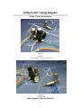
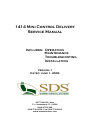
1414 Mini Control Delivery
Service Manual
Includes: Operation
Maintenance
Troubleshooting
Installation
Version 1
Dated: June 1, 2003
6277 NW 28th Way
Ft. Lauderdale, FL 33309
(800) 275-3368
(954) 730-3636 *Fax (954) 730-3602
www.summitdental.com
1
Table of Contents
WARRANTY..............................................................................…..…...…....……3
IMPORTANT INFORMATION..................................................................…...…..4
Operator’s Instructions…..........................................................…..........……5
Flow Diagram...………………………….………….............................….....…...6
PURGING YOUR SYSTEM………………………………………………….…….….7
TROUBLESHOOTING GUIDE………………………………………….…………....8
INSTALLATION INSTRUCTIONS.....................................................…..........…..9
Mounting Unit to Post…………….........................................……..............9
Utility Center Plumbing Layout………………………………………..…….10
Utility Center Tubing Diagram…………………………………….…………11
2
WARRANTY
Summit Dental Systems (SDS) warrants its products against defects in materials or workmanship
from the date of shipment to the Buyer as follows:
Summit Dental Systems (SDS) Equipment:
Chairs, Delivery Units, Cuspidors, Lights
Control Block Diaphragm (part of Delivery Unit)
All Upholstery, Stools, all Plastic Covers, and Cabinets
Warranty Period:
5 Years
Lifetime
1 Year
Summit Dental Systems‟ sole obligation under the warranty is to provide parts for repair, or at its
option, to provide a replacement product (excluding all labor and shipping fees). “In any action,
BUYER‟S remedies are limited to the warranty described above. BUYER shall not be
permitted to claim lost profits, reliance, special, incidental, or consequential damages in
any proceedings.” The warranty does not cover damage from improper installation or
maintenance, accident or misuse. The warranty does not cover damage resulting from the use of
cleaning disinfecting or sterilization chemicals and processes. Failure to follow instructions
provided in Summit Dental Systems‟ Operation and Installation Manuals (Owner‟s Guides) may
void the warranty. In the event Warranty service must be performed to correct any defect, only
an authorized Summit Dental System dealer may perform any and all warranty repairs. Any
repairs by unauthorized dealers, technicians, or repairmen may void the warranty.
In
Inthe
thecase
caseof
ofaadefective
defectivewarranty
warrantyitem,
item,aacopy
copyof
ofthe
thereplacement
replacementinvoice,
invoice,model and serial
number
of the
product
under
which
it wasunder
replaced,
a description
of the
model and
serial
number
of the
product
whichand
it was
replaced, of
andsymptoms
a
defect
must
be
returned
with
the
part
within
30
days
of
the
replacement
invoice
date
to
description of symptoms of the defect must be returned with the part within
th
Summit
Systems, 6277
NW 28
Ft. Lauderdale,
FL 33309,
30 daysDental
of the replacement
invoice
dateWay,
to Summit
Dental Systems,
6277USA,
NW in order to
receive
credit.
Any and allFL
expenses
freight,
labor
perform
warranty
28th Way,
Ft. Lauderdale,
33309,for
USA,
in order
toto
receive
credit.
Any service, and
purchase
of spare for
parts
are thelabor
responsibility
the buyer.
Any and
fraudulent
claims made may
and all expenses
freight,
to performofwarranty
service,
purchase
void
the
warranty.
Any
additional
warranty
that
may
be
provided
by
an
authorized
Summit
of spare parts are the responsibility of the buyer. Any fraudulent claims made
Dental
Systems
dealer isAny
the sole
responsibility
saidmay
dealer.
may void
the warranty.
additional
warrantyofthat
be provided by an
authorized Summit Dental Systems dealer is the sole responsibility of said
SDS
dealer.
reserves the right to make changes or improvements on any products without being
required to modify existing equipment in a like manner.
SDS reserves the right to make changes or improvements on any products without being required
to modify existing equipment in a like manner.
Please complete and retain for your records the following Information:
In case of warranty part replacement/repair or when ordering a part, please call your authorized
Summit Dental Systems dealer and have the following information available:
Owners’ Name:
Phone #:
Model #:
SDS Serial #:
Dealer:
Phone:
Purchase Date:
3
Important Information
Technical Specifications
Air Regulator Pressure:
80 PSI
Water Regulator Pressure: 40 PSI
Handpiece Pressure:
30-35 PSI (for most high-speed handpieces)
40-45 PSI (for most low-speed handpieces)
CAUTION: When adjusting the handpiece pressure, do not over tighten the
screws. This may result in unnecessary damage to the handpiece control block.
Pay careful attention when unpacking the delivery unit and its accessories. Damage
caused by mishandling the equipment during unpacking or installation is not covered
under warranty.
New Owner: Please read, sign and submit the warranty registration form that is
located on page 4 of this manual. Failure to return this form may void the warranty.
Read this manual carefully. If you have any questions, please call SDS Technical
Service at 1-800-275-3368.
SUMMIT DENTAL SYSTEMS
Ft, Lauderdale, FL USA
Product Label Location
The product label can be
located on underneath the
unit head chassis.
MODEL No:
SERIAL No:
PRODUCT:
VOLTS
4
HERTZ
AMPS
Operator’s Instructions
Water Coolant
Flow Control
SDS
WATER
COOLANT
Water
“On/Off”
Toggle
Handpiece
Selection
HIGH
LOW
SUMMIT DENTAL SYSTEMS
Ft, Lauderdale, FL USA
MODEL No:
Product Serial Number
Label is located
underneath Unit Head
Chassis.
SERIAL No:
PRODUCT:
VOLTS
HERTZ
AMPS
Turn the Handpiece Selection switch to the desired handpiece position.
2. The handpieces are automatically activated when removed from their hanger.
3. Depress the Foot Control to operate the activated handpiece. Pressure is shown on the
gauge for the handpiece being used.
NOTE: Individual handpiece pressure adjustments at the back of
the drive air adjustment block, located inside the unit.
To adjust the pressure to each handpiece, turn the adjustment screw
clockwise to decrease pressure or counter-clockwise to increase
pressure.
CAUTION: When adjusting the handpiece pressure, do not overtighten the screws. This may result in unnecessary damage to the
handpiece control block.
4. To activate water spray turn the Water On/Off Toggle to the „On‟ position. It is
located on the left side edge under the control head. Flow adjustment to the „wet‟
handpieces is controlled by the controls labeled „Flow Control‟.
5
1414 Mini Control Flow Diagram
UTILITY CENTER
5-070-0098
Master
On/Off
5-070-0051
Drive Air Manifold
5-020-0145
Water Coolant
On/Off
5-070-0051
Handpiece Air Routing Valve N/O
5-070-0060
Water Flow Control
5-070-0054
Shuttle Valve
5-020-0007
Round Gauge
5-070-0107
Water Relay
5-020-0043
Solids Collector
Assembly
5-030-0024
FOOT
CONTROL
5-020-0024
3-Way Syringe
5-070-0159
Handpiece
Auto Hanger
5-020-0280
Holder
5-020-0280
¼” Orange, Constant air in
1/8” Blue, Coolant water
1/8” Clear, Signal air
1/8” Yellow, Constant air in from Master Valve
Handpiece & Foot Control Tubings
6
Holder
5-020-0280
Purging Your System
Daily Maintenance
Purging with air: At the end of every day, the lines should be purged with air to prevent the
growth of biofilm.
1. Remove handpieces from tubing.
2. Empty the water bottle, then reinstall it (if water bottle is applicable, when using city water,
turn off water from the source).
3. Hold the handpiece tubing and syringe over a pail. Turn the unit on, wait a few moments and
then operate the flush toggle (if applicable), syringe and foot control until water is purged
from the system.
4. Turn unit off.
Disinfecting the bottle (if applicable): Fill the bottle with 100 ml disinfectant
solution, shake vigorously and let settle for 10 minutes. Shake again, and then rinse
twice with water.
Weekly Maintenance
The weekly cleaning procedure should be performed at least once a week, preferably at the start
of the week before treating patients. If the unit is stored for any length of time, perform the
weekly maintenance routine immediately before and after storage.
1. Purge the unit with air (see Daily Maintenance).
2. Flush the system with disinfectant solution:
a. Turn unit off. Empty the water bottle (if water bottle is applicable), replacing the water
with cleaning solution (see Disinfectant Solution).
b. Remove handpieces from tubing and hold the handpiece tubing and syringe over a pail.
Turn unit on, wait a few moments and then operate the flush toggle (if applicable),
syringe and foot control until a continuous stream of solution is running through the
system.
3. Allow the disinfectant to remain in the unit for at least 10 to 20 minutes and then flush the
system again until all the solution is used up.
4. Purge the unit with air:
a. Hold the handpiece tubing and syringe over a pail. Turn the unit on, wait a few moments
and then operate the flush toggle (if applicable), syringe and foot control until all solution
is purged from the system.
b. Turn unit off. (If the unit is to be stored, stop here.)
5. Fill with clean water:
a. With the unit turned off, remove the empty disinfectant bottle (if applicable). Replace
with clan bottle and water.
b. Hold Remove handpieces from tubing and hold the handpiece tubing and syringe over a
pail. Turn unit on, wait a few moments and then operate the flush toggle (if applicable),
syringe and foot control until a continuous stream of solution is running through the
system.
Disinfectant Solution: Use 100 ml (9 parts tap water & 1 part 5.25% Sodium hypochiorite
(household bleach) of disinfectant solution for each application per week. Always use a fresh
mixture every week.
7
Troubleshooting Guide
SYMPTOM
1. Handpiece Lacks Power
PROBABLE CAUSE
A. Check regulator adjustment (80 psi).
B. Check handpiece pressure adjustment on control block.
C. Plugged air filter.
D. Pinched supply tubing. Check for kinks.
E. Bad handpiece gasket at connection with tubing.
F. Defective handpiece.
2. Water coolant does not shut off when Foot Control is
released.
A. Adjust air pressure to 80 psi – water pressure to 40 psi.
B. Foot Control is not exhausting.
C. Defective water relay in valve
3. More than one handpiece is operating.
A. Handpiece is not completely in the hanger.
B. Improper adjustment of Pilot Valve in the hanger.
C. Kinked or pinched signal line from the Pilot Valve.
4. Insufficient water coolant.
A. Adjust coolant flow valve.
B. Water filter may be plugged.
C. Plugged handpiece.
D. Kinked or pinched tubing.
E. Improper adjustment of water relay.
5. Water coolant is running from handpiece while in
holder.
A. Water pressure is too high.
B. Air pressure is too low.
C. Handpiece holder out of adjustment.
6. Water coolant is running continuously.
A. Purge switch is on (on applicable systems).
B. Water pressure is too high.
C. Handpiece holder out of adjustment.
D. Improper adjustment of water relay.
If you continue to experience difficulties, please call Technical Service Team at
1-800-275-3368.
8
Installation Instructions
(4“ from Center)
(Back View of Unit)
1. Space hanging brackets (screws) __” from center on the mounting surface.
2. Slide the Control down the hanging brackets (screws).
3. Install the Control‟s umbilical to the customer supplied utilities (see page 15).
9
Utility Center Plumbing Layout
(Not to Scale & Not Included)
RESERVED FOR
ELECTRICAL
OUTLET
2” OPENING
IN UTILITY
CENTER
AIR IN
½” – 14 NPT
MALE THREADS
9”
VACUUM
¾” PVC
WATER IN
½” – 14 NPT
MALE THREADS
6”
4”
WASTE
¾” PVC
3”
2”
2”
10 1/2”
14”
NOTE: All pipes must be terminated 1 inch above floor.
Position box so that 2” opening faces post side.
10
Utility Center Tubing Diagram
(Utility Center not included)
figure 1
Air Side
Air Regulator (Part # 5-070-0111)
figure 2
Water Side
Water Regulator (Part # 5-070-0103)
11
MT Promedt Consulting GmbH
Altenhofstrasse 80
D-66386 St. Ingbert, Germany
6277 NW 28th Way – Ft. Lauderdale, FL 33309
Phone: (800) 275-3368 www.summitdental.com