1
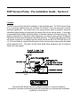
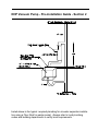
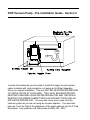
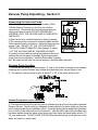
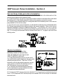
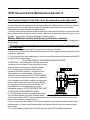
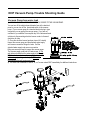
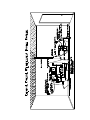
Dansereau
Vacuum Pump
Owners Manual
1 Horsepower
USA Phone: (800) 423-5657
International Phone: (951) 549-1400
Fax: (951) 549-1411
Website: WWW.DHPDENTAL.COM
E MAIL: [email protected]
Manufactured at: 250 E. Harrison Street, Corona 92879
DHP Dental Vacuum Pump - Table of Contents
Section 1 - Vacuum Pump
Section 2- Pre-installation Guide
Section 3 - Unpacking
Section 4 - Installation
Section 5 - Maintenance
Section 6 - Trouble Shooting Guide
Dental Equipment Room Design
DHP Vacuum Pump - Section 1
Dansereau Health Products has been producing dental equipment for over 30 years.
information contained in this manual is a compilation of facts collected over those 30 years.
industry standard for the oral evacuation in a dental office is a liquid ring vacuum pump.
liquid ring vacuum pump has been in use for over 30 years and is the most reliable and
effective method of oral evacuation.
The
The
The
cost
Vacuum Pump System
The vacuum pump system installed in the typical dental office is primarily used for oral evacuation of debris from the patients mouth. Recent changes in the industry have required the
manufacturers of vacuum pumps to add accessories to the vacuum pump to accommodate
those changes.
Air/Water Separator - The function of an air/water separator is to allow the liquid waste
evacuated from the patients mouth to be separated from the air born gases/particles.
The air/water separator is installed after the vacuum pump and before the drain or floor
sink. A 2" vent pipe is required for correct installation of the separator.
Water Recycler - The function of the water recycler is to allow the water used in the operation
of the vacuum pump to be re-used, thus reducing the water usage in the dental office.
Buck Boost Transformer - The function of a Buck Boost Transformer is to increase the voltage
of the electricity supplied to the dental office from the Electric Company. The voltage available in some rural areas of the United States or in some older buildings in urban areas may
not meet the requirements to properly operate a vacuum pump. All vacuum pumps require a
minimum of 120v/208 electricity. It is extremely rare to not have the proper voltage, if you
have any questions regarding the access to the necessary voltage, contact Dansereau
Health Products customer service for additional information.
World Wide Toll-Free Access
DHP has instituted a toll free telephone service in the United States, Canada and Mexico. Our
telefax line (714-776-4652) is available 24 hours a day.
Toll Free Phone:
U.S.A. and Puerto Rico 1-800-423-5657
Canada 1-800-423-5657
Mexico 095-800-423-5657
Customer Service
DHP customer service in-house technicians have a minimum of 10 years experience in the manufacturing, installation and maintenance of the DHP vacuum pump.
Approved Testing Laboratories
ETL Testing Laboratories File Number (ETL) - LISTING # 82327
Canadian Standards Association File Number (CSA) - LISTING # 82327
DHP Vacuum Pump - Pre-installation Guide - Section 2
Location
The DHP Vacuum Pump should be installed in a well ventilated area. The DHP Vacuum Pump
is air cooled and without proper air circulation the lifespan of the vacuum pump could be
shortened significantly. The sound level of the vacuum pump, when in operation, should be
considered when locating an area within the dental office for the vacuum pump. It is strongly
recommended that insulation should be added to the walls adjacent to the vacuum pump. The
ambient temperature in the dental office equipment room should never exceed 40 degrees
Fahrenheit minimum and 100 degrees Fahrenheit maximum. The dental office equipment room
will require a minimum 5 air changes per hour which can be met with a 50 CFM vent fan in a 5'
x 5' x 9' room. Below is a typical elevation layout for the vacuum pump system within the dental
office equipment room. The layout for the entire dental office equipment room is located in
Section 8 of this manual.
The above DHP Dental Vacuum installation elevation is a typical installation.
It should be noted that local building codes will supersede any recommended installation
guidelines in this manual.
DHP Vacuum Pump - Pre-installation Guide - Section 2
Listed above is the typical required plumbing for air water separator installation using a Floor Sink for waste receipt. Always refer to local plumbing
codes and building departments to verify local requirements.
DHP Vacuum Pump - Pre-installation Guide - Section 2
In some circumstances you may wish to install the single vacuum system
under a cabinet with sink connection, not using an Air Water Separator.
Above is a typical installation. This may NOT BE AN APPROVED METHOD
OF INSTALLATION IN YOUR AREA. THE LOCAL BUILDING DEPARTMENT MAY REQUIRE AN AIR WATER SEPARATOR AND THE SPACE
RESTRICTION UNDER CABINET INSTALLATION MAY DISCLUDE AN
AIR WATER SEPARATOR. You may also notice more noise from the
vacuum system as you are not using an air water separtor. You must also
have an 1 Inch Air Gap at the placement of the waste exhaust into the P Trap
Recepticle. Any questions call Dansereau at (800) 423 - 5657.
DHP Vacuum Pump- Pre-installation Guide
Electrical Requirements
LINE VOLTAGE - Single phase 120v/60hz or 240v/60hz electricity is required for proper operation of the DHP Vacuum Pump. All electrical sources to the DHP Vacuum Pump MUST BE
PROPERLY GROUNDED! All DHP single horsepower vacuum pumps are manufactured to
accommodate 120 voltage. The DHP two horsepower vacuum pump systems are manufactured to accommodate 240 voltage.
LOW VOLTAGE - The DHP Vacuum Pump has an ON/OFF low voltage capability. A 18/3 low
voltage rated wire can be run from each operatory or from one central location to allow the DHP
Vacuum Pump to be turned on and off from various locations within the dental office. NOTE: Do
not connect 120v or 240v to the low voltage lines as it will cause internal electrical damage to
the vacuum pump motor.
Plumbing Requirements
WATER LINE - A 1/2" cold water source is required for proper operation of the DHP Vacuum
Pump. A 1/2" shut off valve is required at end of the water source. Cold water is an important
requirement for the proper operation of the DHP Vacuum Pump. If the cold water is restricted
in any manner the DHP Vacuum Pump will malfunction and cause serious damage to the main
seal and impeller of the DHP Vacuum Pump.
WASTE LINE - The industry standard for exhausting the vacuum pump waste is to exhaust the
waste into an Air/Water Separator with the waste ending in a floor sink or a ' P ' trap. Local
Building Codes will require a 1" air gap from the exhaust of the Air/Water Separator into the floor
sink or the ' P ' method of waste disposal.
Vacuum Line
The industry standard is a 1" schedule 40 PVC line reduced to a 3/4" schedule 40 PVC line at
the operatory. Section 8 in this manual will supply additional information regarding the vacuum
line system layout. Current Building Codes may not allow schedule 40 PVC and may require
copper as substitute. It is strongly recommended that you contact your local building department and inquire if schedule 40 PVC is acceptable to use in the vacuum line system fabrication.
Vacuum Pump Specifications:
Total Horsepower - 1
Total CFM - 12hg
Maximum Users:
High Volume Evacuation (HVE) - 2
High Volume Evacuation & Saliva Ejectors - 1(HVE) & 2 (SE)
Height - 13 Inches
Depth - 10 Inches
Width - 13 Inches
UNDER NO CONDITIONS SHOULD CONTINUOUS RUN SINKS OR
DENTAL CUSPIDORS BE INSTALLED ON A VACUUM LINE
Vacuum Pump Unpacking - Section 3
Unpacking the Vacuum Pump
1) The DHP Vacuum Pump weighs approximately 70 lbs.
With the Vacuum Pump box on the floor use a knife to
open the box. Remove all the inner packing material and
various parts and set aside, DO NOT DISCARD ANY
MATERIAL UNTIL THE VACUUM PUMP IS COMPLETELY
INSTALLED.
2) Remove the inner cardboard sleeve by sliding it upward.
3) The vacuum pump is mounted to a plywood pallet carefully
lift the vacuum pump out of the box - realize the vacuum pump
weighs 70 lbs. DO NOT LIFT THE VACUUM PUMP BY
THE WHITE PLASTIC MANIFOLD (See diagram A below)
- LIFT THE VACUUM PUMP BY THE BASE HOUSING.
4) Locate the three rubber mounting feet stapled to the wood
platform the vacuum pump is attached. Remove the vacuum
pump from the wood platform. Install the three rubber mounting
feet. Be careful not the hold the vacuum pump by the white plastic manifold.
Vacuum Pump location
1) Set the vacuum pump on a level surface. A vinyl or tile surface is strongly recommended,
carpeting and or wood surfaces may mildew and deteriorate over several years of use.
2) The optimum vacuum pump location is within 6" to 18" of the waste line/floor sink.
Vacuum Pump water source installation
3) The water source line to the vacuum pump is a flexible burst proof blue tubing with a threaded
fitting on the end. The blue tubing is designed to easily attach to the water angle stop that has
been installed as per the pre-installation guide. As per the drawing below apply either plumbers
putty or teflon to the male portion of the connection. After the teflon tape or the plumbers putty
has been applied thread the water source burst proof blue tubing and hand tighten with an 11/
16" open end wrench. DO NOT OVER TIGHTEN-After the water source line is tight turn on the
water and check for water leaks.
DHP Vacuum Pump Installation - Section 4
Vacuum Pump intake and exhaust installation
4) Locate the flexible white PVC tubing supplied by DHP and attach to the intake portion of the
vacuum pump (labeled on the vacuum pump).
5) Locate the operatory vacuum line source( the plumber installed in the dental office )and attach
the intake portion of the flexible white PVC tubing to the operatory vacuum line source.
6) Locate the second flexible white PVC tubing and attach to the exhaust portion of the vacuum
pump (labeled on the vacuum pump).
7) If you choose to use a vacuum separator you will attach the exhaust portion of the flexible white
PVC tubing (now attached to the vacuum pump) to the vacuum separator. Refer to the Vacuum
Separator installation manual for additional instructions. If you choose not to use a vacuum
separator the flexible white PVC exhaust hose will drain directly into the floor sink or plumbing 'P'
trap. It is strongly recommended that the exhaust hose have a 1" air gap as per most local
building codes.
Electric Installation
IT IS EXTREMELY IMPORTANT THAT THE
ELECTRICAL SOURCE AT THE ELECTRICAL
PANEL BE TURNED OFF UNTIL THE VACUUM
PUMP IS COMPLETELY INSTALLED.
1) Locate the electrical junction box at the end of
the metal flexible conduit attached to the gray metal
vacuum pump junction box. This is the 115 volt
electrical source for the single horsepower vacuum
pump system or the 230 volt electrical source to
the 2 horsepower vacuum pump system.
2) It is strongly recommended that the electrical
portion of the vacuum pump installation be done
by a qualified licensed electrician.
All 1 horsepower DHP vacuum pumps are standard 115 volt and require a dedicated electrical
circuit. All 2 horsepower DHP vacuum pumps are standard 230 volt and require a dedicated
electrical circuit.
DHP Vacuum Pump Maintenance-Section 5
The Vacuum Pump in-line filter must be cleaned on a weekly basis.
If the Vacuum Pump in-line filter is not cleaned on a weekly basis you will experience a significant reduction in
vacuum suction and with continued use under these conditions the additional strain on the Vacuum Pump will
reduce the life of the Vacuum Pump and could void the warranty under misuse of the product clause.
Daily Maintenance-Vacuum System Cleaning/Sterilization
1) With the Vacuum Pump on-take the High Evacuation hose in each operatory and 'suck' an approved vacuum
pump cleaning solution through the vacuum system. Repeat this procedure with the saliva ejector in each
operatory. This procedure will clean and sterilize the vacuum system.
Weekly Maintenance-Vacuum Pump in-line filter cleaning
1) Locate the white plastic bowl filter attached to the white PVC manifold of the Vacuum Pump. (See diagram on
following page)
2) It is strongly recommended that rubber gloves and a face mask be used when the vacuum pump in-line
filter is being cleaned.
3) The Vacuum Pump must be turned off to remove the vacuum pump in-line filter.
4) Refer to In-line Vacuum Pump Filter removal instructions on following page for complete instruction in filter
removal and replacement.
5) If you notice either the black rubber gasket or the in-line vacuum filter screen has deteriorated contact DHP
for replacement parts immediately.
IN VACUUM PUMP FILTER REMOVAL INSTRUCTIONS
1) IMPORTANT - The contents of the in-line filter cannister are
considered to be a biohazard. Wear gloves and face mask
when servicing the vacuum pump in-line filter cannister.
2) The vacuum pump must be turned off in order to
unscrew the in-line filter cannister.3) Unscrew the in-line
filter cannister in a clockwise manner. Strong hand
pressure is all that is required - DO NOT USE A WRENCH !
4) The contents of the in-line filter cannister are considered
to be a biohazard and should be handled in the appropriate
manner. DHP strongly recommends that disposable filters
be used and that you do not reuse the in-line filter. The
disposable filters are to be disposed of by a waste
management company. DO NOT DISPOSE OF THE WASTE
IN THE IN-LINE FILTER CANNISTER IN A SINK !
5) The replacement in-line filter is reinstalled by screwing
the in-line filter cannister in a counter clockwise manner
until it is firmly in place. NOTE: The black rubber gasket on the in-line filter cannister must be in the proper
place in order to ensure no leakage will occur.
6) If you accidently spill the contents of the in-line filter cannister you should wash the area completely with
undiluted bleach or an approved sterilization solution and dispose of the cloth used with a waste management company.
7) If you are incapable of replacing the in-line filter cannister contact DHP for additional assistance.
DHP Vacuum Pump Trouble Shooting Guide - Section 6
Vacuum Pump does not operate
1) Check the electrical sourceA - Locate the electrical panel and verify if the electrical breaker fuse has ' tripped '. Prior to resetting the
electrical breaker fuse visually inspect the vacuum pump for any unusual conditions (water leaks, loose electrical connections etc.). You may attempt to reset the fuse if you are experienced in this procedure. If you are not
comfortable with this procedure it is strongly recommended that you contact an electrician or another person
who is experienced in this procedure. If electrical breaker fuse 'Trips' again contact an electrician immediately.
2) Electrical Source is intact-vacuum pump has electrical power and vacuum pump does not
operate.
A - Turn off the electrical power to the vacuum pump and CAREFULLY FEEL THE SIDE OF THE VACUUM
PUMP MOTOR-BE EXTREMELY CAUTIOUS AS IT MAY BE VERY HOT.
If the vacuum pump motor is hot and not operating when the power is on contact DHP immediately!
B - If the vacuum pump is not hot contact DHP for further instructions.
Vacuum Pump does not supply enough suction
1) Verify vacuum system is oversized for the horsepower of the vacuum pump.
A) Check if the users versus the horsepower rating of the vacuum pump are proper. If the number of users
outweigh horsepower of the vacuum pump you will receive inadequate suction.
B) Verify if the vacuum pump in-line filter has been properly maintained-if not, clean the filter as per the
instructions in the previous section and recheck the suction to verify if it has increased.
C) Verify the dental operatory amalgam traps/filters have been properly maintained. Clean the amalgam traps
and recheck the suction to verify if it has increased.
D) With the vacuum pump operating verify the vacuum gauge is reading between 10 hg and 12 hg as per
operating conditions. If the vacuum gauge does not read between 10 hg and 12 hg verify there are not any
openings to the vacuum system. If any openings to vacuum system are found correct the situation and recheck
the vacuum gauge. If the suction has not improved contact DHP for further instructions.
Vacuum Pump does not supply enough suction to one operatory
A) Verify the high evacuation hose is free and clear of any debris that may have lodged itself in the dental
operatory high evacuation hose.
B) If the dental operatory high evacuation hose does not have any obstruction remove the vacuum system
connection in the dental operatory junction and verify if the suction is sufficient at the connection-if not contact
DHP for further instructions.
Vacuum Pump does not operate-motor humming noise is evident and
the electrical breaker fuse has ' tripped '.
1) The motor impeller is frozen as a result of an obstruction within the bell housing or lack of water. Verify the
vacuum pump is receiving water, water should be exhausting from the exhaust portion of the vacuum pump, if
not, the impeller is frozen as a result of an obstruction in the bell housing - DO NOT ATTEMPT TO OPERATE THE
VACUUM PUMP CONTACT DHP IMMEDIATELY AS YOU MAY DAMAGE THE MOTOR.
Vacuum Pump motor does operate but no suction is evident in the
operatories
1) The vacuum pump motor shaft has broken. DO NOT ATTEMPT TO OPERATE THE VACUUM PUMP CONTACT DHP IMMEDIATELY FOR ADDITIONAL INSTRUCTIONS.
DHP Vacuum Pump-Trouble Shooting Guide
Vacuum Pump has water leak
1) IMPORTANT! DISCONNECT THE ELECTRICAL SOURCE TO THE VACUUM PUMP.
You can turn off the electrical panel breaker fuse at the electrical
panel or you can turn off the operational switch to the vacuum
pump. If your vacuum pump is a standard electrical plug in type
connection you can unplug the vacuum pump. If you are not
confident in your abilities to accomplish any of the aforementioned
solutions to disconnecting electrical source contact a licensed
electrician for help.
2) Once the electrical source has been turned off, visually
inspect the vacuum pump and the attached water supply
and vacuum connection fittings for leaks. If all the
attached water supply and vacuum connection
fitting are secure proceed to inspect the vacuum pump.
The vacuum pump could leak in 3 basic areas. A-The
anti-siphon manifold that the water supply is fed though
B-The sealed area between the mounting plate and
bell housing (see diagram below) C-The seale
area between the bell housing and motor
4) If a water leak is detected in area A, B, or C areas contact DHP immediately for additional instructions.