1
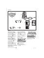
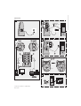
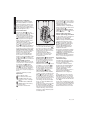
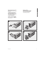
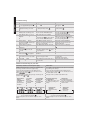
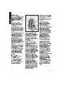
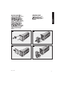
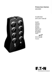
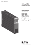
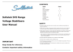
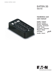
Protection Station
650/800
Installation
and user manual
English
Français
Deutsch
Italiano
Español
Nederlands
Português
Polski
Finnish
MAU-00075 AA
Packaging
1
Protection
Station
2
3
5
4
6
Caution!
◗ Before installing the Protection
Station, read the booklet 3
containing the safety instructions to be
respected. Then follow the instructions
given in this manual 4 .
◗ Lees voordat u het Protection
Station gaat installeren eerst de
veiligheidsinstructies in boekje 3 .
Volg daarna de instructies van deze
handleiding 4 .
◗ Avant l'installation de Protection
Station, lire le livret 3 qui présente
les consignes de sécurité à respecter.
Suivre ensuite les instructions du
présent manuel 4 .
◗ Antes da instalação do Protection
Station, ler o caderno 3 onde
constam as instruções de segurança
a respeitar.
Depois, seguir as instruções do
presente manual 4 .
◗ Vor Installation des Protection
Station die im Heft 3 genannten
Sicherheitsvorschriften lesen.
Anschließend die Anweisungen im
vorliegenden Handbuch 4 befolgen.
◗ Lue tämä ohje ennen Protection
Stationin asennusta
◗ Prima dell’installazione del
Protection Station, leggere
attentamente le istruzioni di sicurezza
riportate sul libretto 3 .
In seguito, attenersi alle istruzioni
riportate sul presente manuale 4 .
◗ Antes de la instalación del
Protection Station, leer el manual 3
que presenta las instrucciones de
seguridad a cumplir.
A continuación, seguir las
instrucciones del presente manual 4
2
◗ Przed zainstalowaniem Protection
Station, nale"y przeczytaç instrukcj´
3 , która zawiera niezb´dne
zalecenia bezpieczeƒstwa.
Nast´pnie nale"y zapoznaç si´ z
zaleceniami zawartymi w niniejszej
instrukcji 4 .
MAU-00075 AB
Quick start
A
C
2 Internet /
modem / fax
B
D
5
E
Beep
OK
OK
>1s
F
Product representations not legally binding.
MAU-00075 AB
3
Operating conditions
ENGLISH
◗ This product is an Uninterruptible
8
10
11
9
7
Power Supply (UPS) for computers
and their peripherals, television sets,
stereo systems and video recorders...
It must not be used to supply other
electrical equipment (lighting, heating,
household appliances, etc.).
UPS connections
◗ Connect the UPS 1 to the ACpower system via a wall outlet with an
earth connector (see figure A).
◗ Plug critical equipment (computer,
monitor, modem, etc.) into the outlets
8 providing battery backup power
and surge protection (see figure B),
taking care not to exceed the rated
current indicated in amperes.
◗ Other devices (printer, scanner, fax,
etc.) can be connect to the filtered
outlets 7 that provide surge
protection (see figure B). The filtered
outlets are not backed up by battery
power in the event of a power outage.
◗ Optional fax/modem connection:
A telephone, fax, modem or Ethernet
data line can be protected against
surges by connecting it to the
telephone outlet via the UPS. The
device cable is used between the
telephone outlet and the UPS, and the
supplied cable 2 is used between
the UPS and the device, as indicated
in figure C.
◗ Optional COM connection:
The 650 and 800 VA devices can be
connected to the computer using the
special USB cable 5 supplied.
The software available on the CDROM 6 (or downloadable from the
eaton.com site) can be configured to
monitor the UPS and the supply of
power to the computer (see figures D
and F).
◗ Follow the indicated procedure.
Operation
7 : Four filtered outlets.
8 : Four battery backup outlets.
9 : LED ON indicate that surge
protection is active on all eight
outlets.
10 : LED ON indicate a UPS fault.
11 : ON/OFF button for the battery
backup outlets.
12 : Protection circuit breaker.
4
12
◗ Battery charge: The UPS charges
the battery as soon as it is connected
to the AC outlet, whether button 11 is
pressed or not. When used for the first
time, the battery will only provide its
maximum autonomy after it has been
charged for 8 hours. It is
recommended that the UPS be
permanently connected to the AC
power supply to ensure the best
possible autonomy.
◗ Filtered outlets 7 without battery
backup: Equipment connected to
these outlets is supplied as soon as
the AC cord is plugged in. They are
not affected by button 11 .
◗ Battery backup outlets 8 :
Equipment connected to these outlets
is supplied as soon as button 11 is
pressed and turns green (see figure
E). These outlets can be turned on
even if the UPS is not connected to
AC power (button 11 flashes).
◗ AC-power disturbance: If AC
power is disturbed or fails, the UPS
continues to operate on battery power.
Button 11 flashes green. In normal
mode, the audio alarm beeps every 5
seconds, then every 2 seconds when
the end of battery backup time is near.
In silent mode (see the section on
customizing), the audio alarm simply
beeps once when the UPS transfers
to battery power.
◗ If the power outage lasts longer than
the battery backup time, the UPS
shuts down and automatically restarts
when power is restored. Following a
complete discharge, a few hours are
required to recharge the battery back
to full backup time.
◗ To save battery power, it is possible
to press button 11 to cut the supply of
power to the devices connected to the
battery backup outlets.
◗ Surge protection: All outlets,
whether backed up or simply filtered,
include surge protection, whatever the
position of button 11 .
◗ Shutdown of the battery backup
outlets 8 : Press button 11 for more
than two seconds.
Master and EcoControl
outlets operating procedure:
In order to limit energy consumption of
peripherals (scanner, printer) in
standby mode, the Protection
Station is equipped with EcoControl
outlets that are dependent on the
Master (see figure B) outlet. When
the main application supplied by the
Master outlet (computer) is shut
down, the EcoControl outlets are
automatically deactivated and the
peripherals shut down.
This function (deactivated by default)
is validated and configured using the
configuration tool integrated in the
Solution-Pac (software supplied with
your Protection Station).
Note: When the function is activated,
do not connect critical applications to
EcoControl outlets.
Threshold setup:
A default setup ensures the correct
operation of the EcoControl function.
However, depending on the
consumption of the main load, the
trigger threshold of the EcoControl
function may have to be modified
using the configuration software
supplied with the UPS:
◗ First, make sure that the function is
activated in the “EcoControl
Function“ tab of the configuration
tool.
◗ If the peripherals connected to the
EcoControl outlets do not switch off
when the main load is not in normal
operation (ex: when in standby mode),
the detection threshold value must be
set to High.
◗ If the rated consumption level of the
main load is low and the EcoControl
outlets shut down when the main load
is operating normally, the detection
threshold value must be set to Low.
MAU-00075 AB
Battery change
◗ Caution. Battery service life is
◗ Warning:take care not to inverse
reduced by 50% for every ten degrees
above 25°C.
◗ The battery must be replaced
exclusively by qualified personnel
(risk of electrocution), with a new
battery approved by Eaton to ensure
correct operation of the UPS.
◗ The battery must be disposed of in
accordance with applicable
regulations. To remove the battery,
shut down the UPS (button 11 OFF),
remove the power cord and proceed
as indicated below.
the polarity + (red) and - (black)
when connecting the batteries as
this will destroy the device.
G
I
H
J
MAU-00075 AB
ENGLISH
Battery disposal and safety
5
Troubleshooting
Problem
Diagnostic
Solution
◗ The battery backup outlets 8
◗ Button 11 is not pressed.
◗ Press button 11 and check that it
◗ The connected devices are not
◗ The devices are not connected to
◗ Connect the devices to the battery
supplied when AC power fails.
the battery backup outlets 8 .
backup outlets 8 .
◗ AC power is available, but the
UPS operates on battery power.
◗ Circuit breaker 12 has been tripped
by an overload on the UPS output.
◗ Disconnect excess equipment and
◗ The filtered outlets 7 are not
supplied.
◗ The wall outlet is not supplied.
◗ Supply power to the wall outlet.
◗ Disconnect excess equipment and
◗ Circuit breaker 12 has been tripped
by an overload on the UPS output.
reset the circuit breaker 12 by pressing
the corresponding button.
◗ Green button 11 flashes
frequently and audio alarm beeps
every 5 secondes.
◗ The UPS frequently operates on
battery power because the AC power
source is of poor quality.
◗ Have the electrical installation
◗ Green button 11 flashes
frequently and audio alarm is
continuous.
◗ The UPS battery backup outlets 8
◗ Disconnect excess equipment
are overloaded.
connected to the battery backup outlets
8.
7
◗ Red LED 10 is on and the
audio alarm beeps every 30
seconds.
◗ A fault has occurred on the UPS.
The battery backup outlets 8 are no
longer supplied.
◗ Call after-sales support.
8
◗ Green LED 9 is off and the
filtered outlets 7 are supplied.
◗ Surge protection is no longer
◗ Call after-sales support.
◗ The telephone line is disturbed
or modem access is not possible.
◗ Surge protection on the telephone
◗ Disconnect the telephone line from
line is no longer provided.
the wall outlet.
◗ Call after-sales support.
◗ Red LED 10 is ON.
◗ The battery has reached the end of
◗ Have the battery replaced.
ENGLISH
1
turns green.
are not supplied with power.
2
3
4
5
6
9
10
reset the circuit breaker 12 by pressing
the corresponding button.
checked by a professional or use
another wall outlet.
provided.
its service life.
Advanced customizing of your UPS:
Sensitivity to variations of the AC power supply
Audio alarm
◗ Only to be used if frequent switching to the UPS battery
due to large variations in the AC supply voltage.
◗ Possibility of deactivating the audio alarm when the UPS
is operating on the battery.
◗ Accessing the programming mode: with the device
◗ Accessing the programming mode: with the device
switched off, press button 11 for 6 s and release it once
LEDs 10 11 9 have come on.
◗ Display of the 3 possible voltage ranges according to the
status of LEDs 10 and 11 :
switched off, press button 11 for 11 s and release it once
the audio alarm sounds.
Normal mode
(factory
configuration):
AC supply
between 184V
and 264V
Low range
mode:
AC supply
between 160V
and 264V
Low and high
range mode:
AC supply
between 160V
and 284V
10 = ON 11 = ON 10 = ON 11 = OFF 10 = OFF 11 = ON
10 11
9
10 11
9
10 11
9
Change from one mode to another by
successively pressing button 11 .
◗ Memorizing the mode: 10 s after the last press of the
button.
6
◗ Display of the 2 possible audio alarm modes:
Normal mode (factory
configuration):
the UPS emits a beep every
10 s when operating on its
battery.
Normal mode
activated:
Buzzer emits long
beep.
Silent mode:
the UPS emits a single
beep when switching to
battery operation and then
remains silent.
Silent mode
activated:
Buzzer emits
short beep.
Change from one mode to another by
successively pressing button 11 .
◗ Memorizing the mode: 10 s after the last press of the
button.
MAU-00075 AB
10
11
9
7
POLSKI
8
12
28
MAU-00075 AB
POLSKI
G
I
H
J
MAU-00075 AB
29
30
MAU-00075 AB
Technical characteristics
◗ UPS power
◗ Nominal input voltage
◗ Input frequency
◗ Voltage/frequency of battery backup outlets
8 in battery mode
Protection
Station 650
Protection
Station 800
650 VA / 400 W
800VA / 500 W
184 V - 264 V, adjustable to 161 V - 284 V
50/60 Hz (46 - 70 Hz working range)
220 V/ 230 V / 240V ± 7% (50/60 Hz ± 1 Hz)
with pseudosinusoidal wave
◗ Total output current for the 8 outlets
◗ Output current of battery backup outlets 8
2.8 A max
10 A max
3.5 A max
◗ Leakage current
0.5 mA
◗ Input protection
10 A resettable circuit breaker
◗ Transfer time
◗ Telephone surge protection
◗ Sealed lead-acid battery
◗ Automatic battery test
◗ Average battery life
◗ Operating temperature
◗ Storage temperature
◗ Operating relative humidity
◗ Operating elevation
◗ Safety standards
◗ Electromagnetic compatibility standards
◗ Warranty
5 ms typical
Tel, ISDN, ADSL, Ethernet
12 V, 7 Ah
12 V, 9 Ah
Once a week
4 years typical, depending on number of discharge
cycles and temperature
0 to 35°C
-25°C to +55°C
0 to 85%
0 to 3000 m
IEC 60950-1, IEC 62040-1-1, CE certified
IEC 62040-2 *
2 years
(*) Warning: This is a class A-UPS product. In a domestic environment, this product may cause radio interference, in which
case, the user may be required to take additional measures.
Performances tested according to IEC 61643-1 (class 3) standard for 8/20 µs surge wave
AC input source protection
◗ Uoc
6 kV
◗ Up
1.7 kV
◗ In
2.8 kA
◗ Imax
8 kA
Dielectric isolation
◗ AC Ground
1500 Vac, 50 Hz
◗ AC / TEL
3000 Vac, 50 Hz
◗ Tel / Ground
1000 Vac, 50 Hz
Temporary overvoltage (TOV)
◗ Uc
◗ Ut
◗ TOV
Energy dissipation
40
250 Vac
400 Vac
1450 Vac
525 Joules
MAU-00075 AB