1
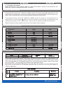
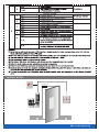
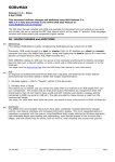
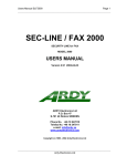
Access Control Keypad
with Waterproof
R
Germany
EMC
tested
Model: YK-1068
Model: YK-1168
Introduction
YK-1068/1168 Standard alone access control realize the card reading and keypad operation
functions, lock, alarm, ring bell, exit button and the magnetic contact switch on the door. The
access host supports 125kHz EM cards (YK-1068B YK-1168B YK-1068A YK-1168A)
It controls 1 door, supports up to 2000 users in total, each user have one card and one PIN.
The access control unit supports 1 master code, one manager add card, one manager delete
card, 1 anti-duress card and 1 anti-duress PIN, providing users with easy operation and safe
guarantee.
Features
Aluminium alloy case, waterproof, fully potted, confirms to IP65
Metal keypad(YK-1168A/YK-1168B) and touch panel(YK-1068A/YK-1068B) optional.
125KHz(EM card) reader (YK-1068A/YK-1068B) Digital backlit key(YK-1168A/
YK-1168B)and touch panel (YK-1068A/YK-1068B).
The back light can be set to Normal ON, Normal OFF or Auto.
With door bell f unction, build-in or external door bell optional.
Multi-function, operating as slave reader, single door, anti-pass back function, etc,
suitable for various occasions.
Specifications
Dimensions: 158.6×43×21.7mm(A) 125×83×21.7mm(B)
Operating voltage range: DC12-24V
Idle input current: ≤35mA
Max proximity card read range: EM card: 3-6cm
Excitation Frequency: 125KHz (YK-1068A/YK-1168A, YK-1068B/YK-1168B)
Card transmit format: Wiegand 26-37
Keypad transmit format: 4-6 digits key press to output card number format,
4 bits or 8 bits data.
Operating temperature range: -40~60° C(EM card)
Operating humidity: 0~95%(non-condensing)
Weight: 0.5kg(A)/0.4kg(B)
1
We create security
Installation and wiring diagram
Pay attention to the sequence during installation
Principle of Door bell Connector
Each press of door bell button, contact of relay in BELL_A
and BELL_B will close contact for 200ms then release.
Principle of Alarm Connector
The field-effec tube will be conducted when alarm is
activated; it will be not conducted when alarm is removed.
Principle of electronic lock
The relay will close contact to unlock the lock and will
release after unlocking
COM: common, relay contact
NC: normal close, normally keep closed to COM
NO: normal open, normally keep opened to COM
Wiring of electronic lock
Connect COM and GND, congnect two ends of electronic lock with +12V and NO
(or NC), complete the circuit.
Type A electronic lock: Fail Secure lock(Unlock when power on),such as Electronic
Controlling Lock, smart lock, etc.
Type B electronic lock: Fail Safe lock(Unlock when power off),such as Electronic
Controlling Lock, Electronic Bolt lock, etc.
1N4004 Diode: prevent high voltage to two ends of the electronic lock while the contact
of relay disconnect. Without diode, there will be high voltage pulse interference to
circuits and the life time of the relay will be greatly reduced.
2
We create security
Manager cards operation
1 Add user card(s)(In dual door mode, users can be only added to zone 1)
Read manager add card, Read Usercard .Read manager add card
Cards can be added continuously.
2 Delete user card(s)
Read manager delete card, Read User card .Read manager delete card
Cards can be deleted continuously.
User Operation
1.To unlock the lock by one card: Read valid card once, the lock will be unlocked.
2. To unlock the lock for card and PIN users
Input 4-6 digits PIN # , the lock will be unlocked.
Read valid card once
3. To unlock the lock for card or PIN users
Read valid card Or Input 4-6 digits PIN # , the lock will be unlocked
4. To unlock the lock for multi cards: Read 2-10pcs valid cards (time interval can not
exceed 5s), the lock will be unlocked
Precondition: Set the door entry by card only, and set “2-10”for opening the door by
multi cards
5. Toggle Mode
In normal mode, Every time a valid card/tag read or PIN input, the replay will operate,
for the pre-set replay pulse time.
Every time a valid card/tag read or PIN input in Toggle mode, the relay changes state,
which will not turn back until read card/tag or input PIN again.
6. To change the PIN of a PIN user
Or
Read card
Input old PIN #
Input new PIN
#
Input new PIN
#
User ID number Input old PIN # Input new PIN # Input new PIN #
Remark:
For users without card, must get ID number and initial PIN from the master. For Zone 1,
the first digit of PIN must be “1”, for Zone 2, the first digit of PIN must be “2”
For the card users with PIN “1234”, must use Reading card to change the PIN for the
first time.
7. Door Bell
Press the door bell button on the access control unit, the buzzer will sound ring back
tone, at the same time, the I box’s built-in door bell or the outer door bell will ring.
Remark: When the work mode is set in Auto Mode (Factory Default Mode), there will
be no ring back tone without the I Box.
Alarm
1. Anti Tamper Alarm
When the access control unit is disassembled illegally, the access control unit’s buzzer
and the external alarm will operate.
2. Door Status Switch
When connect with door status switch, if the door is opened illegal, the access control
unit’s buzzer and the external alarm will operate.
3. Anti-duress alarm
When read zone 1 duress card / input 8digits duress PIN OR zone 2 duress card / input
8digits duress PIN, then press #, the corresponding lock will open, at the same time,
3
We create security
the external alarm will operate, but the access control unit’s buzzer will not operate.
4. To remove the alarm
Read valid card or input master code can remove the alarm. If there is no operation, the
alarm will remove automatically after 1 minute.
To Reset to Factory Default
Keypad access control(YK-1168A/YK-1168B), power off, keep pressing * and power on, the
logo will turn in orange after 1 second, release it until hearing two shot beep , then hearing a long
beep, enter normal mode, reset to factory default setting is successfully.
Touch panel access control(YK-1068A/YK-1068B) ,power off, power on, the logo will turn in
orange after 1 second, press * within 1 second, release it until hearing two shot beep, then
hearing a long beep, enter normal mode, reset to factory default setting is successfully.
Remark: Reset to factory default, the users’ information is still retained.
Sound and Light Indication
Master Setting
Enter Master Operation Mode. it will return to normal mode if there is no right Master PIN
input in 5 seconds. After input of right master PIN, it will also return to normal mode if there
is no valid operation in 30 seconds. press“#” to confirm the input number, return to previous
menu by press“ * ”,the logo light will indicate the operation mode.
Note that to undertake the following programming, the master user must be logged in
1.Basic Operation
4
We create security
5
We create security
INSTALLATION
YM-280(LED)
YP-902-12-3
ABK-800B
YK-1168A/B
6
We create security