1
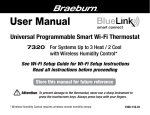
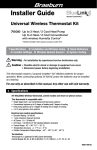
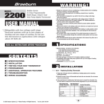
®
User Manual
TM
Universal Programmable
Wireless Thermostat Kit
7500 For Systems Up to 3 Heat / 2 Cool
See Wireless Setup Guide for Wireless Setup Instructions
Read all instructions before proceeding
Store this manual for future reference
©2015 Braeburn Systems LLC • All Rights Reserved • Made in China.
7500-110-01
Contents
1
2
3
About Your Wireless Thermostat Kit
Thermostat Features ................................................3
Thermostat and Display ...........................................4
Control Module .........................................................8
Setting User Options
Advanced User Options ............................................9
Table of User Options ............................................. 10
Service Monitors (Filter, UV and Humidifier Pad) .........11
Extended Hold Time Period ......................................11
Temporary Override Adjustment Limit .....................12
Program Override Time Limit ..................................12
Thermostat Lock Code ...........................................12
Setting Your Program Schedule
Setting the Time and Day .......................................13
Tips Before Setting Your Program Schedule ...........14
Programming a 7 Day Residential Schedule ...........17
Programming a 5-2 Day Residential Schedule ........ 19
Programming a 7 Day Commercial Schedule ......... 20
User Manual
2
4
5
6
Operating Your Thermostat
Setting the System Control Mode .........................22
Setting the Fan Control Mode ...............................23
Setting the Temperature .......................................24
Status Indicators ..................................................25
Communication Loss ............................................26
Remote Sensor - Low Batteries ............................27
Program Event Indicator .......................................28
Resetting the Thermostat .....................................28
Additional Operation Features
Auto Changeover Mode ....................................... 29
Adaptive Recovery Mode .....................................30
Programmable Fan Mode .....................................31
Compressor Protection ........................................31
Locking and Unlocking the Thermostat.................32
AC Power Monitor ............................................... 34
Indoor Remote Sensing ....................................... 34
Outdoor Remote Sensing .................................... 35
Humidification and Dehumidification ................... 36
Thermostat Maintenance
Thermostat Cleaning ............................................38
Battery Replacement ...........................................38
Congratulations! You are in control of one of the easiest-to-use wireless thermostats on the market today.
This thermostat has been designed to provide you with years of reliable performance and comfort control.
Features
• Reliable BlueLink Smart ConnectTM wireless technology
• SpeedBar® multi-function button simplifies programming and setting changes.
• SpeedSet® programming gives you the option of programming all 7 days at once.
• Convenient HOLD feature lets you override the program schedule.
• Large 5 sq. in. bright blue backlit display is easy to read.
• Extra large display characters make viewing settings even easier.
• User selectable service monitors remind you of required system maintenance.
• Precise temperature accuracy keeps you in control of your comfort.
• Convenient programmable fan mode.
• Optional indoor or outdoor remote sensing (wired or wireless).
3
User Manual
1 About Your Thermostat
8
9
10
1
11
12
13
14
15
2
16
3
User Manual
BACK
NEXT
4
5
4
HUMID
6
7
Thermostat Display
1
Room
Temperature....................... .Displays the current room temperature
2
Set Temperature........................... .Displays the current set point temperature
3
Outdoor Temperature Indicator.... .Displays along with the outdoor temperature reading**
4
BACK Indicator*............................ .BACK button is active
5
NEXT Indicator*............................ .NEXT button is active
6
Humidity Indicator ...................... .Indicates when there is a call for humidification or dehumidification
7
Service Indicators . ..................... .Displays various service/maintenance information
8
Fan Indicator................................. .Indicates when the system fan is running
9
Wireless Indicator......................... .Indicates a wireless connection (flashes when connection has been lost)
10
Low Battery Indicator................... .Indicates when the batteries need to be replaced
11
Hold Mode Indicator .................... .Indicates if the thermostat is in HOLD mode
12
Lock Mode Indicator . .................. .Indicates if the thermostat is locked
13
System Status Indicator .............. .Displays information about the status of the system
14
Day of the Week............................ .Displays the current day of the week
15
Program Event Indicator.............. .Displays the program event
16
Time of Day .................................. .Displays the current time of day
* BACK and NEXT are secondary functions of the PROG and HOLD buttons. When in programming or configuration modes, BACK and NEXT appear in the display screen indicating that the PROG and HOLD buttons now function as BACK and NEXT.
** Also see #24 on page 7.
5
User Manual
1 About Your Thermostat
22
INSTRUCTIONS
23
15
BACK
NEXT
18
19
DAY/TIME
16
17
24
25
User Manual
6
20
21
Thermostat
15
Reset Button ................................ .Resets current time, program and user settings
16
SYSTEM Button............................. .Selects the system you want to control
17
DAY/TIME Button........................... .Sets the current time and day of the week
PROG Button................................. .Selects programming mode or press for 3 seconds to select SpeedSet®
BACK Button*................................ .Secondary function of the PROG button - moves back a setting
HOLD Button.................................. .Enters/Exits the HOLD mode (program bypass)
19
NEXT Button*................................ .Secondary function of the HOLD button - moves to next setting
20
RETURN Button............................. .Returns to normal mode from program or setting modes
21
FAN Button.................................... .Selects the system fan mode
22
Quick Reference Instructions....... .Stored in slot located at top of thermostat
23
SpeedBar® .................................... .Increases or decreases settings (time, temperature, etc.)
24
Outdoor Temperature.................... .If a Braeburn® outdoor sensor was connected you can view the outdoor .
temperature by pressing the PROG and HOLD buttons at the same time.
25
Humidity Setpoint......................... .If a Braeburn wireless humidity sensor is connected you can view the
current humidity or make adjustments to the humidity setpoint by
pressing the DAY/TIME and RETURN buttons at the same time.
Battery Compartment................... .Located in the back of thermostat
18
* BACK and NEXT are secondary functions of the PROG and HOLD buttons. When in programming or configuration modes, BACK and NEXT appear in the display, indicating that the PROG and HOLD buttons now function as BACK and NEXT.
7
User Manual
Control Module
Your thermostat communicates wirelessly with a control
module installed on or near your heating/cooling equipment.
This control module is wired directly to your equipment.
NOTE: There is a return air sensor connected to the control
module to maintain default temperature control should
the batteries ever become drained in the thermostat. If the
return air plenum sensor becomes disconnected, the
thermostat will display the words PLEN SENS LOSS. If you
see this message, contact a local service technician.
User Manual
8
2 Setting User Options
INSTRUCTIONS
Advanced User Options
User options allow you to customize some of your
thermostat’s features. Most users will not need to
make any changes to the settings in this section.
INSTRUCTIONS
To access the User Options menu, press and hold
the RETURN button for 3 seconds until the screen
changes and displays the first User Option.
Press the SpeedBar ® or to change the
setting for the displayed User Option. After you
have changed your desired setting, press NEXT
(HOLD) to advance to the next User Option. You
may also press BACK (PROG) to move backwards
through the User Options.
DAY/TIME
BACK
NEXT
When your changes are complete, press RETURN to exit.
DAY/TIME
9
User Manual
Table of User Options
NOTE: Some user options may not be available, depending on how your thermostat was configured in the
Installer Settings (see Installer Manual). A detailed description of each User Option follows this table.
No. User Options
Factory Default
Setting
Options
Comments
Pg.
1 Filter Service
OFF
OFF
Monitor
30, 60, 90,
120, 180, 365
Disables filter service monitor feature.
Selects a number of days that must pass before the 11
thermostat will flash a Service Filter reminder
in the display screen.
2 UV Light Service
OFF
OFF
Monitor
180, 365
Disables UV service monitor feature.
Selects a number of days before the thermostat will 11
flash a Service UV reminder in the display screen.
3 Humidifier Pad
OFF
OFF
Service Monitor
180, 365
Disables pad service monitor feature.
Selects a number of days before the thermostat will 11
flash a Service Humid reminder in the display screen.
4 Extended Hold Period
LONG
LONG
24HR
Selects long (permanent) hold mode.
Selects 24 hour (temporary) hold mode.
11
5
Temporary Override
0 ADJ
Adjustment Limit 0, 1, 2, or 3
ADJ0 Selects a temporary temperature adjustment limit of
0 (disabled), 1˚, 2˚ or 3˚.
12
6
Program Override
4 TEMP
Time Limit
4, 3, 2 or 1
TEMP
Selects a temporary program override time limit of
1, 2, 3 or 4 hours.
12
7
Thermostat Lock Code 0-9 Select a 3 digit lock code of 0-9 for each digit.
12
000
User Manual
10
Service Monitors
(Filter, UV and Humidifier Pad)
User Options 1, 2 and 3
There are three user selectable service monitors that will display
reminders for a required air filter, UV bulb or humidifier pad
replacement. The SERVICE segment flashes in the display
along with FILTER, UV or HUMID. When the service interval
has been reached, and required cleaning or replacement has
been performed, press the RETURN button to reset the
timer. Select OFF or a set number of days before the reminder
will appear.
Extended Hold Period
Service
Reminders
User Option 4
The Extended Hold Period lets you select the period your thermostat will hold the temperature when the HOLD
mode is activated (See Setting the Temperature, page 23). When LONG is selected the thermostat will hold your
temperature indefinitely. When 24HR is selected, the thermostat will hold your temperature for 24 hours and
then return to the current program at that time. Not available in non-programmable mode.
11
User Manual
Temporary Override Adjustment Limit
User Option 5
The Temporary Override Adjustment Limit will limit how
much the temperature can be adjusted from the current set point
when the thermostat is used in the programmable mode. This
setting will not allow the user to override the temperature past
the selected limit amount of 1, 2 or 3 degrees from the current
set point. When the user reaches the adjustment limit the screen
will flash ADJ. A setting of 0 disables the adjustment limit.
The Temporary Override Adjustment Limit can also be used in
the non-programmable mode if the keypad lockout security
level is set to level 1 (See Installer Guide).
Program Override Time Limit
User Option 6
The Program Override Time Limit allows you to set a maximum time limit (in hours) that the thermostat will
return to the program after a temporary temperature adjustment has been made (See Setting the Temperature,
page 24). You may select 1, 2, 3 or 4 hours. Not available in non-programmable mode.
Thermostat Lock Code
User Option 7
The Thermostat Lock Code sets a 3-digit code that you may use at any time to lock or unlock the thermostat.
Setting the code in the user options mode does not activate the lock feature (See Locking/Unlocking Thermostat,
page 32). You may choose a 3-digit code with each digit being 0-9.
User Manual
12
3 Setting Your Program Schedule
Setting the Time and Day
1. In normal operating mode, press the DAY/TIME
button. The display will switch to the day/time
setting mode and the hour will be flashing.
2. Press the SpeedBar® up or down to adjust the
hour, press NEXT.
3. Press the SpeedBar up or down to adjust the
minute, press NEXT.
BACK
4. Press the SpeedBar up or down to adjust the day
of the week.
NEXT
DAY/TIME
5. Press RETURN to exit.
BACK and NEXT are
secondary functions of the
PROG and HOLD buttons.
13
User Manual
Tips Before Setting Your Program Schedule
• Make sure your current time and day of the week are set correctly.
• When programming, make sure the AM and PM indicators are correct.
• Various installer settings such as auto changeover mode and temperature adjustment limits may affect your programming flexibility.
• Your NIGHT event cannot exceed 11:50 p.m.
• BACK and NEXT are secondary functions of the PROG and HOLD buttons (see page 7).
This thermostat has been configured with one of the following programming options:
• Residential 7 day programming mode with 4 events per day (default)
• Residential 5-2 (weekday/weekend) programming mode with 4 events per day
• Commercial 7 day programming mode with 2 events per day
• Non-Programmable mode
NOTE: If this thermostat was configured In the Installer Settings to be
non-programmable, then you cannot set a user program. If you press
the PROG or HOLD buttons, the word “NONE” will appear in the display,
indicating there is no program present. See the Installer Guide for
different configuration options.
User Manual
14
Energy Saving Programs
This thermostat comes pre-programmed with a default energy saving program. The following tables outline
the pre-programmed times and temperatures for heating and cooling in each of your 4 daily events (2 events if
configured for commercial mode). If you wish to use these settings then no further programming is necessary:
Residential 7 Day Programming
Factory Settings
4 Event
All Days
MORN
Time: 6:00 am
Heat: 70˚ F (21˚ C)
Cool: 78˚ F (26˚ C)
DAY
EVE
NIGHT
Commercial 2 Event Programming
Factory Settings
2 Event
Time: 8:00 am
Heat: 62˚ F (17˚ C)
Cool: 85˚ F (29˚ C)
Time: 6:00 pm
Heat: 70˚ F (21˚ C)
Cool: 78˚ F (26˚ C)
Time: 10:00 pm
Heat: 62˚ F (17˚ C)
Cool: 82˚ F (28˚ C)
15
All Days
OCCUPIED
Time: 8:00 am
Heat: 70˚ F (21˚ C)
Cool: 78˚ F (26˚ C)
UNOCCUPIED
Time: 6:00 pm
Heat: 62˚ F (17˚ C)
Cool: 85˚ F (29˚ C)
User Manual
Residential 5-2 Day Programming– Weekday/Weekend
Factory Settings
4 Event
Weekday
Weekend
MORN
Time: 6:00 am
Heat: 70˚ F (21˚ C)
Cool: 78˚ F (26˚ C)
Time: 6:00 am
Heat: 70˚ F (21˚ C)
Cool: 78˚ F (26˚ C)
Time: 8:00 am
Heat: 62˚ F (17˚ C)
Cool: 85˚ F (29˚ C)
Time: 6:00 pm
Heat: 70˚ F (21˚ C)
Cool: 78˚ F (26˚ C)
Time: 10:00 pm
Heat: 62˚ F (17˚ C)
Cool: 82˚ F (28˚ C)
Time: 8:00 am
Heat: 62˚ F (17˚ C)
Cool: 85˚ F (29˚ C)
Time: 6:00 pm
Heat: 70˚ F (21˚ C)
Cool: 78˚ F (26˚ C)
Time: 10:00 pm
Heat: 62˚ F (17˚ C)
Cool: 82˚ F (28˚ C)
DAY
EVE
NIGHT
User Manual
16
Programming a 7 Day Residential Schedule
The 7 day residential programming mode gives you the option to program individual days (1 day at a time) or to
use SpeedSet and program the entire week (all 7 days) with a 4 event program schedule.
Setting All 7 Days at Once (SpeedSet®)
NOTE: Setting all 7 days at once will copy over any previously programmed individual days.
1.Hold the PROG button for 3 seconds. The display will
switch to SpeedSet programming mode. All 7 days
of the week will appear and the hour will be flashing.
2.Press SYSTEM to select HEAT or COOL.
3.Press the SpeedBar® up or down to adjust the hour
for the MORN (morning) event. Press NEXT.
4.Press the SpeedBar up or down to adjust the minute
for the MORN event. Press NEXT.
5.Press the SpeedBar up or down to adjust the
temperature for the MORN event. Press NEXT.
6.Press the SpeedBar up or down to adjust the fan
setting for the MORN event. Press NEXT.
7.Repeat steps 3-6 for the DAY, EVE and NIGHT events.
8.If needed, repeat steps 2-7 to program the opposite mode (HEAT or COOL).
9.Press RETURN to exit.
BACK
NEXT
DAY/TIME
17
BACK and NEXT are
secondary functions of the
PROG and HOLD buttons.
User Manual
Setting Individual Days (7 Day Residential)
1.Press the PROG button. The display will switch to
programming mode. M (Monday) will be displayed
and the hour will be flashing.
2.Press SYSTEM to select HEAT or COOL.
3.Press DAY/TIME to select the day you would like
to program.
4.Press the SpeedBar® up or down to adjust the hour
for the MORN (morning) event. Press NEXT.
5.Press the SpeedBar up or down to adjust the minute
for the MORN event. Press NEXT.
6.Press the SpeedBar up or down to adjust the
temperature for the MORN event. Press NEXT.
7.Press the SpeedBar up or down to adjust the fan setting
for the MORN event. Press NEXT.
8.Repeat steps 4-7 for your DAY, EVE and NIGHT events.
9.If needed, repeat steps 3-7 to select a different day to program.
10.If needed, repeat steps 2-9 to program the opposite mode (HEAT or COOL).
11.Press RETURN to exit.
BACK
NEXT
DAY/TIME
User Manual
18
BACK and NEXT are
secondary functions of the
PROG and HOLD buttons.
Programming a 5-2 Day Residential Schedule
The 5-2 day residential programming mode allows you to program Monday - Friday with one 4 event schedule
and then allows you to change Saturday and Sunday with a different 4 event schedule.
1. Press the PROG button. The display will switch to
programming mode. The days M, TU, W, TH, and F
will be displayed and the hour will be flashing.
2. Press SYSTEM to select HEAT or COOL.
3. Press the SpeedBar® up or down to adjust the hour
for the MORN (morning) event. Press NEXT.
4. Press the SpeedBar up or down to adjust the minute
for the MORN event. Press NEXT.
5. Press the SpeedBar up or down to adjust the
temperature for the MORN event. Press NEXT.
6. Press the SpeedBar up or down to adjust the fan
setting for the MORN event. Press NEXT.
7. Repeat steps 3-6 for your DAY, EVE and NIGHT events.
8. Repeat steps 3-7 for your weekend (S, SU) program.
9. If needed, repeat steps 2-9 to program the opposite mode (HEAT or COOL).
10.Press RETURN to exit.
BACK
NEXT
DAY/TIME
19
BACK and NEXT are
secondary functions of the
PROG and HOLD buttons.
User Manual
Programming a 7 Day Commercial Schedule
The 7 day commercial programming mode gives you the option to program individual days (1 day at a time) or to
use SpeedSet and program the entire week (all 7 days) with a 2 event program schedule.
Setting All 7 Days at Once (SpeedSet®)
NOTE: Setting all 7 days at once will copy over any previously programmed individual days.
1. Hold the PROG button for 3 seconds. The display will
switch to SpeedSet programming mode. All 7 days of
the week will appear and the hour will be flashing.
2. Press SYSTEM to select HEAT or COOL.
3. Press the SpeedBar® up or down to adjust the hour
for the OCCUPIED event. Press NEXT.
4. Press the SpeedBar up or down to adjust the minute
for the OCCUPIED event. Press NEXT.
5. Press the SpeedBar up or down to adjust the
temperature for the OCCUPIED event. Press NEXT.
6. Press the SpeedBar up or down to adjust the fan
setting for the OCCUPIED event. Press NEXT.
7. Repeat steps 3-6 for your UNOCCUPIED event.
8. If needed, repeat steps 2-7 to program the opposite mode (HEAT or COOL).
9. Press RETURN to exit.
BACK
NEXT
DAY/TIME
User Manual
20
BACK and NEXT are
secondary functions of the
PROG and HOLD buttons.
Setting Individual Days (7 Day Commercial)
1. Press the PROG button. The display will switch to
programming mode. M (Monday) will appear and
the hour will flash.
2. Press SYSTEM to select HEAT or COOL.
3. Press DAY/TIME to select an individual day.
4. Press the SpeedBar® up or down to adjust the hour
for the OCCUPIED event. Press NEXT.
5. Press the SpeedBar up or down to adjust the
minute for the OCCUPIED event. Press NEXT.
6. Press the SpeedBar up or down to adjust the
temperature for the OCCUPIED event. Press NEXT.
7. Press the SpeedBar up or down to adjust the fan
setting for the OCCUPIED event. Press NEXT.
8. Repeat steps 4-7 for your UNOCCUPIED event.
9. If needed, repeat steps 3-7 to select other individual days.
10. If needed, repeat steps 2-9 to program the opposite mode (HEAT or COOL).
11. Press RETURN to exit.
21
BACK
NEXT
BACK and NEXT are
secondary functions of the
PROG and HOLD buttons.
User Manual
4 Operating Your Thermostat
Setting the SYSTEM Control Mode
The System Control has 5 modes of operation – AUTO, COOL, OFF, HEAT and EMER. The mode can be selected
by pressing the SYSTEM button to scroll through the different modes.
NOTE: Depending on how your thermostat was configured, some system modes may not be available.
AUTO
The system will cycle between heating and
cooling automatically based on your program
set points. AUTO will be displayed with
either HEAT or COOL.
COOL Only your cooling system will operate.
OFF
Heating and cooling systems are off.
HEAT Only your heating system will operate
EMER Operates a backup heat source
(Emergency Heat) for heat pump
systems only.
User Manual
22
Setting the FAN Control Mode
The Fan Control has 3 modes of operation – AUTO, ON, and PROG. The mode can be selected by pressing the
FAN button to scroll through the different modes.
NOTE: Depending on how your thermostat was configured, some fan modes may not be available.
AUTO The system fan will run only when your
heating or cooling system is running.
ON
The system fan stays on.
PROG The system fan will function in the
AUTO or ON modes depending on your
program schedule.
23
User Manual
Setting the Temperature
SpeedBar
Temporary Adjustment – Press the SpeedBar up or
down to adjust the current set temperature. If your
thermostat is running in 5-2 or 7 day programmable
mode, the set temperature will change back to your
original programmed settings when your next scheduled
change in temperature occurs.
®
Extended Adjustment – Press the HOLD button
so that HOLD appears in the display screen. Press the
SpeedBar up or down to adjust the current set temperature
(See Extended Hold Period, page 10).
NOTE: If this thermostat was configured to be nonprogrammable, you will not have a HOLD option.
User Manual
24
Status Indicators
Status indicators appear in the display to let you know if your system is heating, cooling or off.
Status
Indicator
HEAT ON Heating system is running.
COOL ON Cooling system is running.
AUX
Auxiliary stage of heating is running
(multi-stage systems only)
EMER
Emergency heating system is running
(heat pump systems only)
CHECK
There is a potential problem with your system.
Contact a local service technician.
SERVICE User selectable service reminder for changing a
filter, UV air purifier bulb or humidifier pad
(See Service Monitors, page 10)
ADJ
Temperature adjustment limit has been reached
Thermostat is connected to control module (flashes if connection is lost)
Thermostat battery is low (see section 6)
NO AC
AC power to system has been lost
25
User Manual
Communication Loss
If communication with a wireless device has been lost, the display screen will alternate between COMM LOSS
and the name of the device that has lost communication. See Table 1 for a list of possible device names.
The device will attempt to reconnect with the thermostat automatically, however you can also manually attempt
reconnection by pressing and holding the CONNECT button for 3 seconds on the device (see Installer Guide).
IDS1, IDS2, IDS3 or IDS4
ODS
HMS
CMOD
Remote Indoor Sensor 1-4
Remote Outdoor Sensor
Remote Humidity Sensor
Control Module (see page 8)
Table1
User Manual
26
Remote Sensor - Low Batteries
If batteries become low in a wireless remote sensor, the display screen will alternate between LOW BATT and
the name of the sensor that has the low batteries. See Table 2 below for a list of possible sensor names. Replace
the batteries in the remote sensor as soon as possible (see wireless remote sensor instructions). After replacing
the batteries, the remote sensor will try to automatically reconnect. The reconnection may take up to 15 minutes.
IDS1, IDS2, IDS3 or IDS4
ODS
HMS
Remote Indoor Sensor 1-4
Remote Outdoor Sensor
Remote Humidity Sensor
Requires 2 AA Alkaline Batteries
Requires 2 AA Lithium Batteries
24 VAC Powered - No Batteries
Table 2
27
User Manual
Program Event Indicators
Program Event
Indicator
Program event indicators appear in the display to let you
know what part of your current program is active.
• In Residential Program Mode, MORN, DAY, EVE or NIGHT
will appear.
•In Commercial Program Mode, OCCUPIED or UNOCCUPIED
will appear.
When the program event indicator is flashing, your program
has been temporarily bypassed and will resume at the
next scheduled event.
NOTE: You will not see a program event indicator while in HOLD or Non-Programmable Mode.
Resetting the Thermostat
This thermostat provides you with a reset button that will
erase all of your user settings and programming.
The reset feature does not affect the Installer Settings.
To reset the thermostat, use a small object such as a
tooth pick or paperclip and gently press the button located
inside the small hole on the front of the thermostat housing
labeled “RESET ”.
NOTE: You cannot reset the thermostat if it is locked.
User Manual
Reset
Button
28
5 Additional Operation Features
Auto Changeover Mode
Auto Changeover mode is a feature enabled/
disabled in the Installer Settings (see Installer
Guide). If enabled, it is selected by pressing the
SYSTEM button until AUTO HEAT or AUTO COOL
appears in the display.
When Auto Changeover mode is enabled and
selected, the system automatically switches
between heating and cooling when the room
temperature meets the programmed heating or
cooling set points. To operate properly, the
thermostat requires a “dead band” setting to
eliminate program conflicts. The dead band is set
in the Installer Settings (See Installer Guide). The
default setting is 3° F. Therefore, you will not be able
to set your heat or cool temperature within 3° F of each other. If a setting is made in either heating or cooling
which violates the dead band, the opposite mode will adjust up or down automatically to maintain the programmed dead band spacing.
29
User Manual
Adaptive Recovery Mode (ARM™)
Adaptive Recovery Mode is a feature enabled/disabled in the Installer Settings (See Installer Manual).
If enabled, the feature is automatically present while in programmable mode.
Adaptive Recovery Mode tries to reach your desired heating or cooling temperature at the time you have set in
your current program schedule, after a setback period. For example, if you set your heat down to 62° at night
and have a set point of 70° scheduled for 7:00 AM, the thermostat may turn on your heating system early in
order achieve a temperature of 70° by 7:00 AM.
This feature does not operate when the thermostat is in HOLD mode, if the program is temporarily overridden or
if emergency heat is selected on a multistage heat pump system.
User Manual
30
Programmable Fan Mode
Programmable Fan Mode is selected by pressing
FAN until PROG appears in the display. It is only
available in programmable mode.
Programmable Fan Mode allows the user to run
the fan continuously during a selected program
event. To use this feature, select fan ON while
setting program events. (See “Setting Your
Program Schedule”, page 14).
Compressor Protection
DAY/TIME
Compressor protection is enabled/disabled
in the Installer Settings (See Installer Guide).
If enabled, this feature is automatically present in
cooling and/or heating modes.
This thermostat includes an automatic compressor protection delay to avoid potential damage to your system
from short cycling. This feature activates a short delay after turning off the system compressor.
Additionally, for multi-stage heat pump systems, this thermostat provides cold weather compressor protection by
locking out the compressor stage(s) of heating for a period of time after a power outage greater than 60 minutes.
This cold weather compressor protection can be manually overridden at any time by changing the system mode
to OFF momentarily, then back to HEAT.
31
User Manual
Locking and Unlocking the Thermostat
Your 3-digit Lock Code is set in the “User Options”
portion of this manual (See “Setting User Options”,
page 9 and 12). Once the code is set, the
thermostat can be locked or unlocked at any
time by entering that code.
To lock or unlock the thermostat, press and hold the
DAY/TIME and HOLD buttons together for 5 seconds.
The screen will change, displaying 000 and LOCK
will be flashing. Press the SpeedBar® or to
enter the first digit of your lock code and then press
NEXT* to advance to the next digit. Repeat this
process to enter the second and third digit of your
lock code. After entering the third digit, press RETURN.
BACK
DAY/TIME
*BACK and NEXT are secondary functions of the PROG and HOLD buttons.
User Manual
32
NEXT
If you entered a valid code the thermostat will be locked or unlocked
(depending on its previous state). When locked, the word LOCKED
appears in the display (Figure 1). If an invalid code is entered the
word NO will briefly appear, indicating that an incorrect code was
entered (Figure 2).
Figure 1
Figure 2
33
User Manual
AC Power Monitor
The AC Power Monitor feature is enabled in the Installer
Settings (See Installer Guide). If enabled, this feature will
automatically be present.
If your thermostat was hardwired (power provided from the system
with batteries as a backup) then the AC Power Monitor feature will
indicate when a loss of power to the thermostat has occurred by
displaying NOAC.
Indoor Remote Sensing
Indoor remote sensing is achieved by installing a Braeburn® wired or wireless remote indoor sensor and is
configured in the Installer Settings (See Installer Guide).
If a Braeburn indoor remote sensor was installed and properly configured in the Installer Settings, the thermostat
will sense temperature at a remote location or at a combination of a remote location and the thermostat location.
User Manual
34
Outdoor Remote Sensing
Outdoor remote sensing is enabled by installing
a Braeburn® wired or wireless remote outdoor
sensor. No additional configuration is required.
If a Braeburn outdoor remote sensor was installed
you may press the PROG and HOLD buttons at the
same time to view the outdoor temperature.
DAY/TIME
35
User Manual
Humidification and Dehumidification
If this thermostat was also equipped with
a wireless humidity sensor, it can be used to
control a whole house humidifier or dehumidifier.
Humidification can be controlled manually from
the thermostat or automatically when a outdoor
remote sensor is installed and configured in the
Installer Settings (See Installer Guide).
HUMID
To view the current humidity level at the thermostat,
press the DAY/TIME and RETURN buttons at the
same time (Figure 1). If humidification and
dehumidification are not enabled, you will only see
the current humidity level.
DAY/TIME
Figure 1
If humidification is enabled you will see the current humidity
level along with the humidification set point (Figure 2). Press the
SpeedBar®up or down to adjust the humidification set point.
HUMID
Figure 2
User Manual
36
If humidification and dehumidification are both enabled you will
first see the current humidity level along with the humidification
set point. Press the SpeedBar® up or down to adjust the humidification
set point. Press DAY/TIME and RETURN again to display the
dehumidification set point. Press the SpeedBar up or down to adjust
the dehumidification set point (Figure 3). Press RETURN.
NOTE: If Automatic Humidity Control was enabled in the Installer
Options, the humidification set point may be automatically adjusted
to compensate for changes in outdoor temperature.
DEHUMID
When there is a call for humidification the word HUMID
will appear in the screen (Figure 4). When there is a call for
dehumidification, the word DEHUMID will appear.
Figure 3
HUMID
Figure 4
37
User Manual
6 Thermostat Maintenance
Thermostat Cleaning
Never spray any liquid directly on the thermostat. Using a soft damp cloth wipe the outer body of the thermostat.
Never use any abrasive cleansers to clean your thermostat.
Changing the Batteries
This thermostat requires two (2) properly installed “AA”
alkaline batteries to maintain the thermostat clock and to
provide power for the thermostat if 24 volt AC power is not
connected. (See Installer Manual).
If batteries become low, a battery indicator will appear
in the display. You should change your batteries immediately
when you see the low battery signal by following
these instructions.
1.
2.
3.
4.
+
+
Remove thermostat body by gently pulling it from base.
Remove old batteries and replace with new batteries.
Make sure to correctly position the (+) and (-) symbols.
Gently push thermostat body back onto base.
NOTE: We recommend replacing the thermostat batteries annually or if the thermostat will be unattended for
an extended period of time.
User Manual
38
Limited Warranty
When installed by a professional contractor, this product is backed by a 5 year limited
warranty. Limitations apply. For limitations, terms and conditions, you may obtain a full
copy of this warranty:
· Visit us online: www.braeburnonline.com/warranty
· Write us: Braeburn Systems LLC
2215 Cornell Avenue
Montgomery, IL 60538
Store this manual for future
reference.
Stor
e reference.
www.bluelinksmartconnect.com
5
YEAR
LIMITED
WARRANT Y
®
®
Braeburn Systems LLC
2215 Cornell Avenue • Montgomery, IL 60538
Technical Assistance: www.braeburnonline.com
844-BLU-LINK (844-258-5465) (U.S.)
630-844-1968 (Outside the U.S.)
©2015 Braeburn Systems LLC • All Rights Reserved • Made in China.
7500-110-01