1
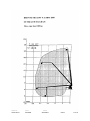
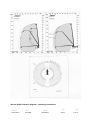
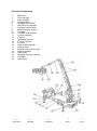
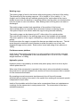
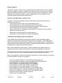
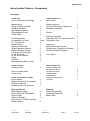
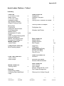
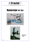
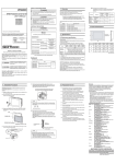
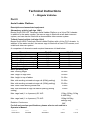
Technical Instructions 1 – Brigade Vehicles Part 9 Aerial Ladder Platform Description and associated equipment Shrewsbury vehicle (call sign 18A1) Bronto Skylift F32 HDT Telescopic Aerial Ladder Platform on a Volvo FM 9 chassis. In addition to the water monitor, the rescue cage is fitted with a talk back intercom system, and can also be fitted with a demountable video camera system. Telford Central vehicle (call sign 19A1) Bronto Skylift HD32 Telescopic Aerial Ladder Platform with a Volvo FL10 chassis. In addition to the water monitor, the rescue cage is fitted with a fixed CCD camera, and a talk back intercom system. A comparison of dimensions and required clearances is listed below: Dimension Overall width Overall width (with outriggers) Overall length (inc. overhang) Overall height Turning circle (kerb to kerb) Turning circle (swept circle) Max gross weight TC ALP 2.5m 5.4m 10.2m 3.5m 17.7m 20m 26t SY ALP 2.5m 5.4m 10m 3.9m 15m 18m 22.6t Main operating data Max. working height 32.00m Max. height to cage floor 30.00m Max. height to top of ladder 31.00m Max. side working outreach at cage rail (400Kg setting) 21.00m Max. side working outreach at cage rail (180Kg setting) 23.00m Max. down reach below ground level 5.00m Max. side outreach at cage rail narrow jacking (400Kg setting) 9.00m Max. cage load (1 to 4 persons) SY ALP. 130kg, 220kg, 310kg & 400.00kg Max. cage load (1 to 4 persons) TC ALP. 180kg & 400kg settings only. Rotation: Continuous 360° For full and concise specifications, please refer to each vehicle’s Operator’s Manual. Reference Author TECH1PT9 FleetCM Status Amended Date Page 09/14 1 of 14 Reference Author TECH1PT9 FleetCM Status Amended Date Page 09/14 2 of 14 Bronto Skylift Outreach diagram – operating instructions Reference Author TECH1PT9 FleetCM Status Amended Date Page 09/14 3 of 14 Principal Components 1. 2. 3. 4. 5. 6. 7. 8. 9. 10. 11. 12. 13 14 15 16 17 18 19 20 21 22 23 Main frame Front outrigger Rear outrigger Outrigger beam Outrigger jack cylinder Rear axle lock (optional) Outrigger control centre Booms transport support Turntable Turntable control centre 1st boom cylinders 1st boom Telescopic sections 2nd boom cylinder 2nd boom Cage levelling cylinder Working cage Working cage control centre Rotation gearbox Cable chain Outrigger extension cylinder Foot plate Centre post Reference Author TECH1PT9 FleetCM Status Amended Date Page 09/14 4 of 14 Operators Only those personnel who have attended the Service’s ALP Operators Course are allowed to operate the appliance. At all times two operators are required to operate the ALP. Operational fire and rescue service personnel who have undergone familiarisation training at Shropshire Fire and Rescue Service are entitled to ride in the cage; they must always wear the safety harness provided. Other personnel may only ride in the cage once the Incident Commander/Officer in Charge of the station and/or operators have assessed the risk; all personnel riding in the cage must wear the safety harnesses provided. Non fire service personnel should only be allowed to ride in the cage in exceptional circumstances for valid operational reasons. They must always wear the safety harness. At all other times requests should be referred to the Executive Officer. See also Brigade Order Administration 9, Part 3 - Community Visits to Fire Service Premises’ page 6. Water Monitor The water monitor is connected onto the piping system and it is placed at the front of the cage on the right-hand side just outside of the railing. The monitor is capable of a delivery of 3800 l/min. It has a protective water spray curtain that operates throughout 360 around the cage. Main Frame The main load bearing element of the aerial device is the strong main frame which takes all the loads caused by the operation of the ALP. The hydraulic oil tank is integrated into the main frame, the tank is fitted with oil level gauge, temperature gauge, suction connections with closing valves for easy maintenance and draining outlet with closing valve. At each end of the main frame there are integrated housings for outriggers. Stabilising System The stabilising system consists of four hydraulically powered outriggers mounted in their housings in the main frame. Each housing is fitted with adjustable guides to provide smooth and accurate movement of the outrigger beam. The horizontal beam is a completely closed steel profile enclosing the hydraulic cylinder for the horizontal movement and the hydraulic hoses for the cylinder of the vertical movement, protecting those devices from external damage. On the SY ALP the stabilising system is a variable system which means that the outriggers can be deployed into any convenient position required by the operator. The on-board outreach computer then calculates the maximum boom distances achievable for the position of each leg. There are two independent automatically operating and self-controlling safety systems to prevent an unsafe configuration to be reached. The stabilising system also includes a rear axle locking system. All controls for the entire stabilising system are located in a dust and waterproof locker at the rear of the vehicle. Reference Author TECH1PT9 FleetCM Status Amended Date Page 09/14 5 of 14 On the TC ALP the outriggers can be placed at any position; however, the vehicle has only two positions which it will recognise, either outriggers fully in or outriggers fully out. In the middle of the control panel there are following additional control devices: starting of chassis engine stopping of chassis engine activating hydraulic pressure visual indication for extended left outriggers visual indication for extended right outriggers visual indication for applied rear axle locking (if the feature is installed) main switches with visual indication operating hour gauge + total operating hour gauge switch for the battery driven back-up for the hydraulic system visual indicator for levelling of the vehicle (along and across the chassis) automatic plumbing system Turntable The turntable is a fully integrated steel welded structure. The centre post containing slip rings with double pins for electrical connections, 100mm stainless steel waterway and hydraulic pressure and tank lines allows continuous rotation of the turntable. Rotation reduction gear with automatically operating braking system is installed at the front of the turntable. The hydraulic motor powering the rotation movement is fitted directly into the gear for high reliability. At the left-hand side of the turntable is the lower control station and at the right-hand side the rescue ladder. Booms There are two booms; the first boom with telescopic extension providing direct movement and the second boom with vertical movement of approximately 180 degrees. The second boom provides an up-and-over capability of approximately 8m throughout its vertical movement. All telescopic sections of the first boom move synchronised i.e. there are no intermediate jerks when the extension/retracting is operated. Rescue Ladder A stable telescopic rescue ladder system is attached onto the right-hand side of the booms. Due to the telescopic design the ladder forms a direct continuous rescue way with no cross-over platform or similar obstacle, this makes the ladder suitable for horizontal rescue. Both control panels are fitted with visual indication for ‘rounds in line’ position on the ladder. Reference Author TECH1PT9 FleetCM Status Amended Date Page 09/14 6 of 14 Working cage The working cage is fixed to the booms with pivoting point at the level of the railing. The dimensions of the working cage are 1,0 m (length) x 2,0 m (width) x 1,1 m (height) and it is fitted with two inwards opening doors, one located at the rear to enable access from the decking in travelling position and the other one located at the front for access in case of a rescue. Safe working load is 400 kg when no water is discharged. The working cage remains level regardless of the position of the booms. The levelling system is controlled by an automatic horizon monitoring device. The system may be over ridden when the cage is being lowered manually. The working cage can be slewed up to 45° either side of its central position. The controls are located in the working cage and at the turntable control panels. The centre position of the cage is indicated by a visual indication at both control panels. At all times when the cage is occupied the harness provided must be worn. The fall arrest lanyard connected to each harness must be secured to one of only two designated cage anchor points. Each anchor has a load rating of two persons or 180kg. Fold down rescue platform At the front of the working cage there is a rescue platform with manually operated safety railing. The dimensions of the rescue platform are 1,45 m x 0,5 m. It has a weight restriction of 180kg. Hydraulic system Hydraulic power is provided by a double axial piston pump, which is driven by the vehicle power take-off. When one of the movements is operated, the control valve automatically increases the pressure to a pre-set constant level and the oil flow to the amount that is needed for the movements activated. By operating several movements simultaneously the oil flow will increase automatically according to the need in the system thus making all movement speeds independent of each other. Inside of the turntable and at the lower valve compartment there are instantaneous couplings for the manometer in each pressure line. The manometer is fitted as a standard equipment. Reference Author TECH1PT9 FleetCM Status Amended Date Page 09/14 7 of 14 Electric System The electric supply is taken from a separate battery system which is kept charged when the engine is running. Voltage of the system is 24V DC and all circuits have been fitted with their specific fuses. When the main current is switched on, yellow flashing warning lights located on each outrigger boom and underneath of the working cage are automatically switched on. Controls and indicators in driver’s cab In addition to chassis standard controls and indicators the following items are installed in drivers cab: visual warning for the main current being switched on visual warning for any of the equipment lockers being open visual warning for the booms not being fully housed to travel position visual warning for the rear axle lock being engaged visual warning for the outriggers not being fully in retracted to travel position switch for the main current switch with visual indication for rotating beacons switch with visual indication for reverse working light Turntable and working cage control panels The turntable control panel incorporating all control levers and safety system indicators is fitted with a swing arm at the side of the turntable. This enables the whole control panel to be placed and locked in its operating position. If desired, the control panel can be swung and locked in a position enabling direct access from the decking of the vehicle into the control station. Both control panels are exactly alike. At the turntable control panel there is a change-over switch to select the panel from which the operation is controlled. The Shrewsbury ALP has control panels that are fitted with Bronto computers which are used to control various functions, and also provide working information. Both control panels are fitted with warning, indication and control devices, all marked by clear symbols for ease of recognition: – – – – – – – – – – – visual and audible indication for exceeding safe working load visual warning for activation of working cage collision guard system visual indication for ground pressure left outriggers visual indication for ground pressure right outriggers visual indication for the rescue ladder ‘rounds in line’ visual indication for the centre position of the booms visual indication for the centre position of the working cage starting and stopping of chassis engine/backup engine (Hatz) switch for the battery driven back-up for the hydraulic system separate control levers for each movement control lever for cage slewing Reference Author TECH1PT9 FleetCM Status Amended Date Page 09/14 8 of 14 – – – – emergency stop button overriding of the automatic working cage levelling system manual operation for the working cage levelling system switches for activating the bleed down system Bodywork and equipment lockers All lockers are fitted with hinged doors, properly sealed to be water and dust proof. All doors are fitted with automatic switches activating the lights as soon as the door is opened and also activating the warning in drivers cab to indicate that all doors are not fully closed. The Shrewsbury ALP is also fitted with central locking on all locker doors and is activated by a rocker type switch on the appliance dash board. The vehicles have integral steps provided which allows access from ground level. Water way The water way system is made of stainless steel and fitted with flexible joints at the first / second boom knuckle position and at the boom / cage location. The nominal diameter of the water way is 100mm and it leads from the rear of the vehicle where a 4 x 65mm (2½”) inlet is fitted through the centre post in the turntable up into the working cage where the water monitor is mounted. Along the booms, the piping is fitted onto the right-hand side in a well-protected position between the boom and the rescue ladder. The centre post, which is mounted in the centre line of the turntable, provides continuous rotation even if water supply is simultaneously used. The piping is protected from possible overpressure by means of a relief valve mounted underneath the turntable. Piping ends at the right-hand side at the front of the working cage where the water monitor is placed. A 75mm valve is fitted in the cage to isolate the monitor if required. There is an additional outlet with 65mm (2½”) closing valve and coupling for water supply from the cage through an extension hose. There are drain cocks fitted in the piping to enable it to be drained after use. On the front underneath of the cage there are nozzles for water spray curtain system to protect cage occupants from radiant heat. Back up for the hydraulic system There is a battery driven hydraulic pump, which provides an independent means of power in case of failure of the main engine. The system can be used from all control panels. It is for emergency makeup procedures only. Reference Author TECH1PT9 FleetCM Status Amended Date Page 09/14 9 of 14 Communications Audio Primary: handheld radios on designated channel incorporating microphone/earpiece. Back-up: audio communications system utilising an integral intercom between the cage operator and the vehicle operator. Video The Fire Emergency Remote Observation System (FEROS) is a portable wireless video monitoring and recording system suitable for rapid deployment in arduous conditions at fire incidents to provide visual observation, monitoring and surveillance. It consists of a portable monitor/control unit housed in a rugged case and a remote camera head unit designed for quick attachment to various types of aerial platform. The monitor/control unit incorporates a joystick for proportional control of pan/tilt movement and camera zoom, a 10” LCD monitor is built into the lid of the monitor/control unit that allows the image from the camera to be viewed easily and clearly. A Sony GVD digital video recorder is also provided that allows the images to be easily recorded, this recorder uses mini DV format tapes and has extensive facilities for editing with a USB connection and memory stick that facilitates easy extraction of moving or still images to a computer. High Wind Warnings It is the responsibility of the operator to periodically check the wind speed monitor on the appliance during use. Each vehicle is fitted with a wind speed indicator which relays to the monitor the wind speed. The maximum wind speed at which the appliance can be operated is 14 metres per second / 31 miles per hour. On the Shrewsbury ALP, when the reading is at 12 metres per second a warning is given. Operating instructions Technical operating instructions are included in the user manual. User inspection and maintenance requirements All vehicle defects must be reported to Fire Control, who will enter the defect on the fleet defects spreadsheet. If the defect requires the appliance to go off the run the duty mechanic will be paged to attend. Station personnel are also required to record all defects in FB440 ‘Appliance Journey Log Book’ under the section ‘Appliance Defect Log’. When the defect has been rectified the mechanic will sign off the defect in the log as complete. Reference Author TECH1PT9 FleetCM Status Amended Date Page 09/14 10 of 14 Reporting of driving and operating accidents All driving and operating accidents must be reported immediately to Fire Control. Refer to Health and Safety Brigade Order 9 Part 5 ‘Reporting and Investigation of Service Vehicle Incidents’. Safety Information Safety devices All load bearing hydraulic cylinders are fitted with lock valves directly integrated into the cylinder structure to prevent the booms, the working cage or the outriggers from retracting in case of a pipe or hose failure. Retracting of any of the outriggers is automatically prevented as soon as the booms have been lifted from their travelling position. Similarly lifting of the booms from the travelling position is prevented until the outriggers have reached the support width and ground pressure. All boom movements have been limited at their most extreme positions thus making it impossible for the operator to reach an unsafe configuration by normal means of operation. The movements having direct influence on the stability of the aerial ladder platform are all fitted with two separate limiting circuits, the first one stopping that particular movement, the second one deactivating the whole electric and hydraulic system should the first circuit fail. The major movements, lifting of the first boom to its maximum elevation, and extending or housing the telescopic movement or lowering the first boom at the maximum outreach have been fitted with slow-down devices to provide smooth deceleration of the movement. Starting of the chassis engine/backup (Hatz) from any of the control panels of the aerial is prevented unless the gear is shifted to neutral. An emergency stop switch is fitted at both boom control panels and jacking station to provide immediate and complete ‘freezing’ of all systems in case of an unexpected emergency. The turntable and cage control centres are fitted with ‘dead man switches’ to provide additional safety. There is a ‘bleed down’ system which can be operated from working cage and turntable control panels. By means of this system the booms can be lowered and the working cage brought down onto the ground even if no hydraulic pressure is available. In such a case manual rotation is possible. Records to be maintained Workshops will maintain electronic maintenance records. Reference Author TECH1PT9 FleetCM Status Amended Date Page 09/14 11 of 14 Appendix A Aerial Ladder Platform - Shrewsbury Inventory Crew Cab Red Torches-Non Recharge 2 Maps various Siting & Pitching Guider Handheld Radios Alp Operator Manual Rechargeable Torch Traffic Tape 1 2 1 1 1 Fire Extinguisher Sunglasses (UV safe) Hi – Viz Jackets Mobile Phone Nominal Roll Board White Operators Helmet Makita Distance Gauge Fire ground Feeding Box HI Vis Sur-coats Hi Vis Storm Jackets Pager Sat Nav Bag containing Misc. Leads 1 1 pair 2 1 1 3 1 1 2 2 1 1 1 Deck Lockers Jacking Plates 4 Front n/s shoe locker Snow socks 1 Front Transverse Locker Hose Ramps Basket Stretcher & Foot board White/Long Board Bridle/Harness for stretcher 2 1 1 1 Rear Locker o/s Blue Flashing Lamp Akron Branch & HR Adapter Short Length Warning Triangle Chimney Kit In Yellow Carryall Rubble Sacks Reference Author TECH1PT9 FleetCM 6 1 3 2 Front Locker n/s Bolt Cutters 1 Sledge Hammer Pan and Tilt Head (in black box) Wooden Footplates 1 1 3 Shovel 1 Warning Triangles Extension Pole for Camera System Firefighter’s Axe Large Axe Body Harness & Lanyard Ceiling Hook, Extension & Handle Chimney Rods & Scrapers 8 1 1 1 1 4 1 2 First Aid Kit 1 Rear Locker n/s Dynafor Load Cell 3m two ton sling 2m two ton sling Snatch Block D Shackles Camera Control Unit Tool Kit 1 1 1 1 6 1 1 External Descending Ladder Collecting Head with Blank Caps 1 1 4 2 Status Amended Date Page 09/14 12 of 14 Appendix B Aerial Ladder Platform - Telford Inventory Crew Cab Hi Vis Storm Coats Maps various Hi Vis. Sur Coats Handheld Radios Alp Operator Manual Siting & Pitching Guide Bump Hats First Aid Kit Hand Held Anemometer Fire Extinguisher Mobile Phone Sunglasses (UV safe) Pager Hand Torches-Rechargeable Nominal Roll Board Makita 15m Range Finder Fire ground Feeding box Middle Locker n/s Jacket Plates Lower Front Locker n/s Blue Flashing Lamps Front Top Locker n/s Traffic Cones Hose Ramps Middle Locker o/s Jacking Plates External Descending Ladder Collecting Head with Blank Caps Reference Author TECH1PT9 FleetCM 2 2 2 1 1 3 1 1 1 1 2 pair 1 3 1 1 1 2 6 6 2 2 1 1 Front Locker n/s Megaphone Harness & Lanyard Shovel Ceiling Hook, Extension & Handle 1 4 1 1 Chimney Rods & Scrapers 2 Firefighters Axe 1 Wooden Jack Plates 3 Rear Locker n/s Rubble Sacks Sledge Hammer Bolt Cropper 2 1 1 pr Large Axe D Shackles Snatch Block & Pulley 3m Two Ton Sling 2m Two Ton Sling 30m GP Line 1 4 1 1 1 1 Front Top Locker o/s Stretcher 1 Stretcher Foot Board Stretcher Bridle/Harness 1 1 Rear Locker o/s Akron Branch Short Length Monitor Control & Ext. Lead Dry Powder Extinguisher 1 2 1 1 Chimney kit in Yellow Carryall 1 Status Amended Date Page 09/14 13 of 14 Appendix C Mobilisation Where the predetermined attendance (PDA) of a premises requires an aerial appliance, Fire Control will despatch the Shrewsbury ALP (FFH) 18A1. If that appliance is committed then the Telford ALO (FFH) 19A1 will be mobilised. When a new property is identified as requiring an aerial appliance as part of the PDA the Assistant Group Commander (AGC) should ensure that the ALP can gain access to the property and that it can be safely sited. If necessary the ALP should visit the property. Any requests for Special Services, other than those required to save life or stabilise structures in immediate danger of collapse, should be referred to the Executive Officer. Reference Author TECH1PT9 FleetCM Status Amended Date Page 09/14 14 of 14