1
The basic programmable robotic kit for everyone
Enjoyable programmable robotic kit that
includes building parts, microcontroller,
sensors and an easy to use programming
software that uses graphical based iconic
logo language.
!"#!$%#&!'&()
*+,-%#&!'&()
./+%$-#&!'&()
*01#*+,-%
Step by step from starting to the intelligent
robot with sensors.
1
System requirements
Hardware
You will need either a PC or laptop computer to
run the Robo-CIRCLE software. Getting started with
Robo-CIRCLE is easiest if your PC or laptop has the
following features:
! Harddisk space 15MB
! 800 x 600 Resolution Color Monitor. 1024 x 768
COM port
recommended.
! A serial or USB port (requires USB to serial port
converter for USB port - optional)
! A CD-ROM drive, World Wide Web access, or both.
Software
! Install Windows ME or newer operating system.
Windows XP Service-pack2 is highly recommended.
Window Vista and Windows 7 is also supported.
RS-232 serial port may be called
COM port. Normally installed
at the back of computer.
It provides 9-pin male D-type
connector (called DB-9 male
connector).
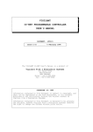
Cable information :
CX-4 cable
COM port interfacing cable between controller board with computer
Conductor side
Female DB-9 connector
Computer’s side
JST3AA-8 cable
Ground
4-pin modular plug
Microcontroller’s side
pin 2 - RxD (Serial data receiver pin)
pin 3 - TxD (Serial data transmitter pin)
pin 4 - DTR (Data terminal ready)
pin 5 - GND (Ground)
3-wire cable for interfacing the sensor and application module
Signal wire
8-inch
+5V
2
Getting started with the
Computer has only USB port
Optional
Install batteries
USB<>COM port
CX-4 cable
Notebook computer
UCON-232S
USB interface
Serial (COM) port interface
CX-4 cable
AA size Battery
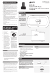
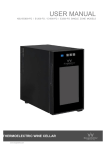
i-BOX III supports
simple Alcaline
batteries and
Rechargeable
batteries.Use 4
“AA”(not included).
Desktop computer
Digital output
connect with ZX-LED
or Relay driver circuits
POWER switch
Analog input
Turn ON or OFF the supply
voltage to all circuit
connect with Infrared
"#$#%&'"() *+,-& (#.('"(
Motor output
Digital input
Simple DC motors DC
motor gearboxes
Motor direction indicator
connect with Switch/
Touch sensors
Microcontroller
Forward
Backward
RUN/STOP switch
The brain of Robot,
contains Logo inter/"#&#" 0"123"#
[3] Beep!
Stop program
Run program
[1] Turn on
[2] LED on
First step with
(1) Flip the i-BOX upside down and open the battery
cover to place 4 “AA” batteries into the battery holder.
Please ensure that the polarity of the placement of your
batteries are correct in order for the i-BOX to function.
(2) Turn on POWER switch. The Red LED light will blink
a few times followed by a Beeping sound from its
speaker
3
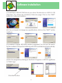
Software installation
(1) Insert Robo-CIRCLE CD-ROM into your drive. Double-click on i-BOX III V133
setup.exe. You will see the Installation Welcome page. Click on the “NEXT”
button to Continue installation.
456 78 9' .'& .##9 &' %-3.,# 3.: (/#%+0%3&+'.() %;+%< '. &-# =>?@AB CD&&'.
continue.
(3) Installation is started. i-BOX Utility window is appeared. Yuo can use it for searching the available COM port for interfacing with i-BOX controller board automatically.
(4) Run the program by clicking on the Start > Programs > i-BOX III LogoBlocks
or Criket Logo.
Click Start button
4
How does the i-BOX interface with
my computer
Direct serial connection to COM port of your computer with the CX-4 cable.
Direct connect to working
COM port
Connect USB port using the UCON-232S USB to Serial converter device.
E(+., &-# EFG /'"&) :'D 2+;; 0"(& .##9 &' +.(&3;; &-#
driver provided by the USB to Serial converter
device which is optional.
(1) Back to the installation CD-ROM, open UCON-232
EFG H"+I#" 8';9#" &' 0.9 &-# USBdriverInstallerV2.xx.exe.
H'DC;#J%;+%< '. &-+( 0;# &' (&3"& +.(&3;;3&+'.K
(2) Plug in the UCON-232S to the USB port. The computer
will connect with the UCON-232S automatically. The blue
LED of UCON-232S turns on to show a READY connection.
(3) Connect the CX-4 cable between the UCON-232S
and the i-BOX controller.
UCON-232S
CX-4
5
How to choose the COM port interfacing
Search and choose by i-BOX III Center software
USB<>COM port
UCON-232S
Notebook computer
CX-4 cable
CX-4 cable
Desktop computer
(1) Connect the CX-4 cable between i-BOX and the computer’s COM port.
(2) Run the i-BOX III center by clicking on the Start > i-BOX III > i-BOX III Center.
(3) The i-BOX III Center software will search the COM port available of your computer and
connect with the i-BOX automatically.
(4) Click on the LogoBlock or the CricketLogo to start the software.
Check and choose with your own
(1) Click the right button mouse on My Computer icon to choose Properties. The System
Properties window is appeared. Select Hardware > Device Manager. Choose Ports listing
(COM & LPT). Observe the number of Communication port (COMx). If using the UCON-232S
device, the port name will display USB Serial Port (COMx) instead. Remember the COM port
number to set in the software later.
(2) For the LogoBlocks software, select menu Edit > Preferences.. Choose the COM port
interfaced from step (1) and click on the OK button. For Cricket Logo, you can set the COM
port interfaced at the Serial port combo box on the main screen.
Choosing COM port
of LogoBlocks
6
Choosing COM port
of CricketLogo
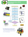
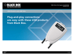
How to develop Robo-CIRCLE
programming
Robot programming procedures
Construct the robot
and attach sensors
Construct the robot.
Connect the download cable
to i-BOX III controller.
COM port
Connec
t the dow
nload
cable to
COM po
rt.
Connect the cable between
robot and computer
Create code with
LogoBlocks or CricketLogo
Cricket Logo
Download the code
Test code
Edit the code
Does the code run correctly ?
Incorrect
locks
Logo B
Correct
Ending
de.
Edit co
Robo-CIRCLE development is divided into 3 parts.
Part-1 : Prepare and construct the Robot from
chassis, motors, wheels and other mechanical parts
Part-2 : Learn about i-BOX controller and Sensors
Part-3 : Controlled program
7
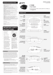
Command block
summary of LogoBlocks
LogoBlocks is a unique software that lets you create iconic programs to control the
i-BOX III controller. To create programs, you just drag blocks form the palette (on the
bottom left of the screen) and snap them together on the canvas (on the right side
of the screen). The buttons on the bottom left let you switch between palettes, each
containing a different set of commands.
Motor control, Sound
and Timer command
Condition and loops command
Drive motor
Interrupt
Stop motor
Stop interrupt
Brake motor
Repeat loop
Forward direction
Loop operation
Backward direction
Reverse direction
Wait condition
Set power to motor
Check conditions
Set time of motor control
Check additional conditions
Send HIGH logic
Stop program operation
Send LOW logic
Beep generation
Sensor functions command
Musical generation
Set delay time
Digital input block
Reset timer value
Sensor block
Read timer value
Serial data checking
nop : No operation
Serial data buffer
Serial data monitor
Procedure functions command
Delete data block
Record value to memory
Set of rules block
Clear Data Pointer
Procedure icon
Recall data from memory
Beep
Set data pointer
Start sub procedure
8
Command block
summary of LogoBlocks
Number functions and arithmetic command
Declare variable
Set number
Random numerical
Numerical comparison (Less than statement)
Numerical comparison (Equal statement)
Numerical comparison (More than statement)
AND : logical block operation
OR : logical block operation
XOR : logical block operation
NOT : logical block operation
Adding
Subtraction
Multiplying
Divided
Modulus
9
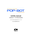
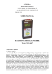
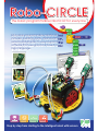
ZX-LED : The LED output board
introduction
How it work ?
The ZX-LED is digital output device module. The LED will lit when get the logic “1”
Signal connector
8mm. LED
Transistor current
!"#$%&'()*'(+'$,$-.(/01
ZX-LED schematic diagram
A light emitting diode (LED) emits light when current passes through it. The color of the LED usually just tells you what
color it will glow when current passes through it. The important markings on an LED are contained in its shape.
Since an LED is a one-way current valve, you have to make sure to connect it the right way, or it won’t work as intended.
LED has 2 terminals. One is called the anode, and the other is called the cathode. On the schematic symbol, the cathode is the line across the point of the triangle and part drawing. For the part drawing, note that the LED’s leads are
different lengths. The longer lead is connected to the LED’s anode, and the shorter lead is connected to its cathode.
ZX-LED includes a transistor to drive current for supporting the low source current output port of microcontroller.
It ensures the LED on when the logic “1” applied to input.
Interfacing with i-BOX III
ZX-LED is an output device. This must be connected to
P0 and P1; the digital output port of i-BOX III controller
8';;'2+., &-# 0,D"# '. ;#8&K A-#"# +( 3 L %'113.9 C;'%<
for controlling the ZX-LED
Set P0 as logic “1” (+5V)
Set P1 as logic “1” (+5V)
Set P0 as logic “0” (0V)
Set P1 as logic “0” (0V)
10