1
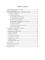
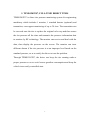
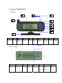
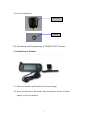
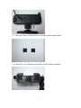
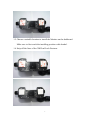
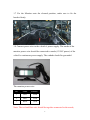
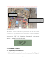
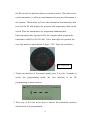
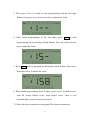
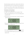
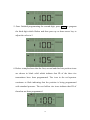
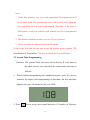
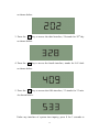
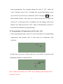
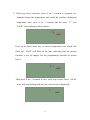
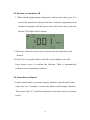
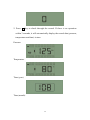
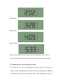
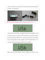
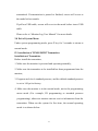
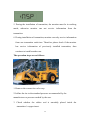
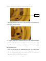
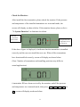
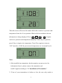
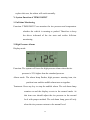
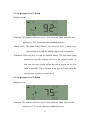
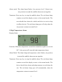
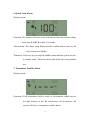
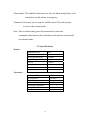
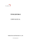
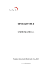
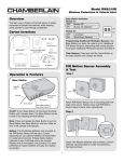
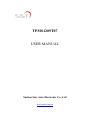
TPMS1209T07
USER MANUAL
Suzhou Sate Auto Electronic Co., Ltd
www.sate.com.cn
1
Table of Contents
I. TPMS1209T07, Full-time Direct TPMS-------------------------------------------------3
II. Parts of TPMS1209T07 -------------------------------------------------------------------4
III. Installation and Programming of TPMS1209T07 Monitor-----------------------5
1. Installation of Monitor---------------------------------------------------------------5
2. Programming of Monitor----------------------------------------------------------9
2.1 Programming of Transmitter ID---------------------------------------------9
2.2 Standard Pressure Programming-------------------------------------------13
2.3 System Time Programming--------------------------------------------------15
2.4 Programming of Temperature and Pressure Unit ----------------------17
2.5 Deletion of Transmitter ID---------------------------------------------------19
2.6 Alarm Record Inquiry --------------------------------------------------------19
2.7 Upload pressure log and alarm records -----------------------------------21
2.8 Exit of System Menu-----------------------------------------------------------23
IV. Installation of TPMS1209T07 Transmitter------------------------------------------23
Installation of Transmitter--------------------------------------------------------------23
V. System Function of TPMS1209T07 ---------------------------------------------------28
1. Full-time Monitoring ------------------------------------------------------------------28
2. High Pressure Alarm ------------------------------------------------------------------28
3. Low pressure level 1 alarm -----------------------------------------------------------29
4. Low pressure level 2 alarm------------------------------------------------------------29
5. High Temperature Alarm -------------------------------------------------------------30
6. Quick Leak Alarm ----------------------------------------------------------------------31
7. Transmitter Trouble Alarm-----------------------------------------------------------31
VI. Specifications -----------------------------------------------------------------------------32
VII. Frequently Asked Questions ----------------------------------------------------------33
VIII. Warranty Term ------------------------------------------------------------------------35
IX. Important Notes --------------------------------------------------------------------------36
2
I. TPMS1209T07, FULL-TIME DIRECT TPMS
TPMS1209T07 is direct tire pressure monitoring system for engineering
machinery which includes 1 monitor, 1 standard booster (optional) and
transmitter, can support monitoring of up to 38 tires. The transmitter can
be screwed onto the tire to replace the original valve cap and then senses
the tire pressure all the time and transmits the pressure information data
to monitor by RF technology. The monitor can receive and deal with the
data, then display the pressure on the screen. The monitor can issue
different alarms if the tire pressure is at an improper level based on the
standard pressure, so as to notify the driver to treat the problem.
Through TPMS1209T07, the driver can keep the tire running under a
proper pressure so as to avoid excess gasoline consumption and keep the
vehicle in an easily controlled state.
3
II. Parts of TPMS1209T07
1. Monitor
⑧
①
⑦
⑨
②
③
④
⑤
⑥
⑩
①
②
③
④
⑤
⑥
⑦
⑧
⑨
⑩
Direction
key↑
S key
Direction
key→
Direction
key↓
P key
Alarm
lamp
Direction
key←
LCD
screen
Antenna
Mounting
bracket
①
Screen Display
②
⑥
⑦
③
⑧
④
⑤
①
②
③
④
⑤
⑥
⑦
⑧
Temperature
unit F
Temperature
unit ℃
Pressure
unit PSI
Pressure
unit KPA
Pressure
unit BAR
Fast
leak
alarm
icon
Transmitter
trouble
alarm icon
Pressure
alarm
icon
4
2. Parts of transmitter
Transmitter
Locknut
III. Installation and Programming of TPMS1209T07 Monitor
1. Installation of Monitor
1.1 Take out monitor and bracket from the package.
1.2 Insert the bracket to the back of the monitor as shown in below
picture to fix the monitor.
5
1.3 Take out a pair of 3M Dual Lock Fastener and separate them.
1.4 Fasten the 2 pcs fasteners with those on the monitor bottom.
6
1.5 Choose a suitable location to install the Monitor on the dashboard.
Make sure to first scrub the installing position with alcohol.
1.6 Strip off the liner of the 3M Dual Lock Fastener.
7
1.7 Fix the Monitor onto the cleaned position, make sure to fix the
bracket firmly.
1.8 Connect power wire to the vehicle’s power supply. The anode of the
monitor power wire should be connected to anode (12/24V power) of the
vehicle’s continuous power supply. The cathode should be grounded.
The monitor power wire:
No.
Color
Electric
1
Red
VDD
2
Blue
VDD
3
Black
GND
Note: The red and blue wire should be together connected to the anode,
8
and the black wire to the cathode. Make sure wires are well connected.
The cathode should be
connected to the iron.
The red and blue wire should be together
connected to the anode (12/24V power) of
the vehicle’s continuous power supply.
Screen Display:
The monitor starts to work after it is powered. At this time the monitor
cannot receive any information as the transmitters are not installed. The
screen shows “NSP” (No Transmitters Programmed), which means
monitor is waiting for receiving the signal.
2. Programming of Monitor
2.1 Programming of Transmitter ID
Before install the transmitter, the user has to program last 3 digits of
9
the ID into the tire position shown on monitor screen. Then after screw
on the transmitter, it will sense and transmit tire pressure information to
the monitor. The monitor will save the information automatically after
received the ID and display the pressure and temperature data on the
screen. Then the transmitters are programmed and matched.
Each transmitter has 4 groups of ID, for example when program the
transmitter with ID of 001 001 001 158 to front right tire position, the
user only needs to input the last 3 digits “158”. Steps are as follows:
last 3 digits of ID
1. Under any interface of the normal mode, press P key for 3 seconds to
access the programming mode, the first interface is for ID
programming as shown below:
2. Press any of the four arrow keys to choose the transmitter position
which needs to be programmed.
10
3. Then press S for 3 seconds to start programming and the first digit
flashes, then press up or down arrow key to adjust the value.
4. Once finish programming of the first digit, press
→
to start
programming the second digit which flashes. Press up or down arrow
key to adjust the value.
5. Press
→
again to program the third digit which flashes. Press up or
down arrow key to adjust the value.
6. When finish programming these 3 digits, press S for 3 seconds to save
with the screen flashes twice, beep buzzes twice. Then it will
automatically switch to next tire position.
7. Follow the above operations to program ID of other transmitters.
11
Note: The tire position with ID programmed will be shown in solid black
icon and the tire position being programmed will continue to flash.
There are 38 tire position icons in this interface. The method to
sequence tire position is increasing from the top-down, from left to
right as shown below:
#4
#3
#5
#6
#1
#2
#38
If tire position icon shows nothing, it indicates that ID of the tire
transmitter has been programmed and saved by the monitor. (If the user
wants to inquire the details of the tire position, please refer to
“Deletion
of transmitter ID” for more details.)
Above figure shows that the first and second tire position icons
“disappear”, this indicates that the ID of these two tire transmitters have
been programmed and saved by the monitor. Under the deletion of
transmitter ID interface, the user can inquire the details of the two tires.
12
The third and fourth tire position icons are shown by black solid icons
which indicate that ID of the two tire transmitters have been programmed.
The sixth tire icon continues to flash in the figure indicating that the tire
transmitter is being programmed. The rest hollow tire icons indicate that
ID of them have not been programmed.
2.2 Standard Pressure Programming
For example, set the standard pressure of first tire position to 105psi:
1. When finish programming ID, press P to access the standard pressure
programming mode.
2. Then press any of the four arrow keys to choose the desired tire
position to program.
3. Then press S for 3 seconds to set the first digit which flashes. Press up
or down arrow key to adjust the value.
4. Once finished programming the first digit, press
→
to program
the second digit which flashes and then press up or down arrow key to
adjust the value.
13
5. Once finished programming the second digit, press
→
to program
the third digit which flashes and then press up or down arrow key to
adjust the value to 5.
6. Below example shows that the first, second and third tire position icons
are shown in black solid which indicate that ID of the three tire
transmitters have been programmed. Tire icon in the red aperture
continues to flash indicating that the position is being programmed
with standard pressure. The rest hollow tire icons indicate that ID of
them has not been programmed.
14
Note:
1. Under this interface, tire icon with transmitter ID programmed will
be in black solid. The standard pressure makes sense only when the
tire transmitter ID has been programmed. Therefore if the icon is
solid black, it only has relation with whether the ID is programmed
or not.
2. The default standard pressure is set to 100 psi in factory.
3. 38 tire positions are always shown in this mode.
If this is the first time for the user to use the system, please inquire “IV.
Installation of Transmitter” directly to finish the first installation.
2.3 System Time Programming
Function: The system clock was preset in the factory. It is the base of
the alarm record, user can check the current date and time as
follows:
1.When finished programming the standard pressure, press P to access
interface for inquiry and programming of time/date, the first interface
displays the year, 08 stands for the year 2008:
2. Press
↓
key to access the second interface, 02 stands for February
15
as shown below:
3. Press the
↓
key to access the third interface, 28 stands for 28th day
as shown below:
4. Press the
↓
key to access the fourth interface, stands for 9 O’clock
as shown below:
5. Press the
↓
key to access the fifth interface, 33 stands for 33 min.
As shown below:
Under any interface of system time inquiry, press S for 3 seconds to
16
start programming. For example change the year to “09”, under the
“year” interface, press S for 3 seconds, the second digit flashes, press
up or down key arrow key to adjust the value. Then press →
key, the
third number flashes, then press up or down arrow key to adjust the
value to“9”. At last press S for 3 seconds to save the change with screen
flashes twice and beep buzzes twice. Then it automatically switches to
next interface (Month) for programming.
2.4 Programming of Temperature and Pressure Unit
1. After programming time, press P to access interface for programming
temperature and pressure unit, it first enters the temperature unit
interface:
At this time, press up or down arrow key can switch to pressure unit
displaying interface as shown below.
Note: Under this interface, the “PSI” unit is flashing which indicates the
currently set unit.
17
2. Under any above interface, press S for 3 seconds to program. For
example change the temperature unit: under the interface displaying
temperature unit, press S for 3 seconds and the units “℃” and
“UNIT” start flashing as shown below:
Press up or down arrow key to choose temperature unit which will
flash, the “UNIT” will flash all the time indicating that the present
interface is not the inquiry but the programming interface as shown
below:
Then press S for 3 seconds to save with beep buzzes twice. All the
icons will stop flashing and only the selected unit is displayed.
18
2.5 Deletion of transmitter ID
1. When finish programming temperature and pressure unit, press P to
access the transmitter deletion interface. Only the programmed and
matched transmitter will be shown with solid wheel icon, and only
the last 3 ID digits will be shown:
2. Press any of the four arrow keys to locate the wheel position to be
deleted.
3. Press S for 3 seconds to delete with the screen flashes twice and
beep buzzes twice to confirm the deletion. Then it automatically
switches to next transmitter location.
2.6 Alarm Record Inquiry
1. Under normal mode or pressure inquiry interface, press P and S at the
same time for 3 seconds to access the alarm record inquiry interface.
The screen with “0” is the first and most recent alarm record, as shown
below:
19
2. Press → key to check through the record. If there is no operation
within 3 seconds, it will automatically display the record data (pressure,
temperature and time) in turn.
Pressure
Temperature
Time (year)
Time (month)
20
Time (date)
Time (hour)
Time (minute)
Then it will display the next alarm record in the same way as above.
3. Press P and S at the same time to return to pressure inquiry interface.
2.7 Upload pressure log and alarm records
The product can save tire information and the recent 180 pieces of
alarm records automatically when the system is operating. In addition,
the monitor can record the pressure data of the transmitters every 30
21
minutes within the recent half year. The user can upload the data in the
computer by USB-RS232.
When insert the USB cable,screen will display as shown below:
Now system is in the mode waiting for information uploading, and all
the buttons can not be used until the USB cable is pulled out. Connect
the other end of the USB cable to computer, and then open the Monitor
Log receiving software in the computer. Click the upload button of the
software, monitor will upload the data as shown below:
Black solid icon will continue to move to indicate the data is being
22
transmitted. If transmission is paused or finished, screen will revert to
the mode before transfer.
If pull out USB cable, screen will revert to the mode before insert USB
cable.
Please refer to “Monitor Log User Manual” for more details.
2.8 Exit of System Menu
Under system programming mode, press P key for 3 seconds to return to
normal mode.
IV. Installation of TPMS1209T07 Transmitter
Installation of Transmitter
Before install the transmitter,
1. Make sure the monitor is powered and operating normally;
2. Make sure the transmitter to be installed has been programmed into the
monitor;
3. Program each tire’s standard pressure, and the default standard pressure
is set to 100 psi in factory.
4. Make sure the monitor is in the normal mode, not in the programming
menu mode (For example, ID programming or standard pressure
programming), otherwise monitor can not receive information from the
transmitter. When use the system for first time, the normal operating
mode is as shown below:
23
5. During the installation of transmitter, the monitor must be in working
mode, otherwise monitor can not receive information from the
transmitter.
6. During installation of transmitter, monitor can only receive information
from one transmitter each time. Therefore please check if the monitor
has receive information of previously installed transmitter, then
continue to install another one.
The operation steps are as follows:
1. Remove the current tire valve cap.
2. Inflate the tire to the standard pressure recommended by the
manufacturer or pressure needed by the user.
3. Check whether the rubber seal is smoothly placed inside the
transmitter’s copper insert.
24
4. Screw the locknut onto the screw thread of the tire valve.
Locknut
5. Screw the transmitter onto the tire valve and then fix the transmitter by
screwing the locknut inversely.
6. Check the connection of transmitter and valve with the soap solution to
confirm whether the transmitter is firmly screwed onto the valve or not,
check whether there is air leakage caused by the installation or the seal of
the transmitters or not.
7. Once screwed onto the tire, transmitter can sense the pressure inside
the tire and transmit the data to the monitor, and the information will
appear on the screen within about 6 minutes.
25
Check the Monitor:
After install the first transmitter, please check the monitor. If the pressure
and temperature of the installed transmitter are in normal mode, the
screen will display as shown below. If the monitor alarms, please refer to
“V. System Function” to eliminate tire alarm.
The first
transmitter
ID has been
Tire pressure and
temperature are in
normal level.
If the above figure is displayed, it indicates that the transmitter is installed
correctly and the user can install the next one. When all the transmitters
have been installed correctly, screen will display as shown below:
(Note: Number of transmitters and installing positions may differ in
actual applications)
6 transmitter ID have been received by the monitor, and all the pressure
and temperature are in normal mode, then press
P
, screen
will display as shown below:
26
↑
↓
←
→
or
Then the screen will access the mode which show each tire’s pressure and
temperature from the #1 tire position. Black solid icon indicates the tire
information is being displayed. Press
↑
↓
←
or
→
to inquire
each tire’s pressure and temperature manually. Under any tire position,
press S key to inquire tire temperature. Press S key again to return to
“ON” interface. (If all the pressure and temperature are in normal level.)
Note:
1. After installed one transmitter, but the monitor can not receive the
information from it, please remove the transmitter and
install it again according to “IV. Installation of Transmitter”.
2. If one of your transmitters is broken or lost, the user only needs to
27
replace this one, the others will work normally.
V. System Function of TPMS1209T07
1. Full-time Monitoring
Function: TPMS1209T07 can monitor the tire pressure and temperature
whether the vehicle is running or parked. Therefore to keep
the driver informed of the tire state and realize full-time
monitoring.
2. High Pressure Alarm
Display mode:
Function: The system will issue the high pressure alarm when the tire
pressure is 25% higher than the standard pressure.
Alarm mode: The alarm lamp flashes, high pressure warning icon, tire
position icon and the audible alarm turn on together.
Treatment: Press any key to stop the audible alarm. The red alarm lamp
remains on and the display reverts to the normal mode. At
this time user should adjust the tire pressure to the normal
level with proper method. The red alarm lamp goes off only
when the tire pressure returns to the normal level.
28
3. Low pressure level 1 alarm
Display mode:
Function: The system will issue level 1 low pressure alarm when the tire
pressure is 10% lower than the standard pressure.
Alarm mode: The alarm lamp flashes, low pressure level 1 alarm icon,
tire position icon and the audible alarm turn on together.
Treatment: Press any key to stop the audible alarm. The red alarm lamp
remains on and the display reverts to the normal mode. At
this time the user should inflate the tire to proper air level as
soon as possible. The red alarm lamp goes off only when the
tire pressure returns to normal level.
4. Low pressure level 2 alarm
Display mode:
Function: The system will issue level 2 low pressure alarm when the tire
pressure is 15% lower than the standard pressure.
29
Alarm mode: The alarm lamp flashes, low pressure level 2 alarm icon,
tire position icon and the audible alarm turn on together.
Treatment: Press any key to stop the audible alarm. The red alarm lamp
remains on and the display reverts to the normal mode. The
user should slow down the vehicle and drive to service shop
to inflate the tire. The red alarm lamp goes off only when the
tire pressure returns to normal level.
5. High Temperature Alarm
Display Mode:
Function: When the temperature around the transmitter equals or exceeds
90℃, the system will issue the high temperature alarm.
Alarm Mode: The alarm lamp and temperature value flashes, tire position
icon and the audible alarm turn on together.
Treatment: Press any key to stop the audible alarm. The red alarm lamp
remains on and the display reverts to the normal mode. The
driver should slow down and adopt measure to cool down the
tire. The red alarm lamp goes off automatically when the
temperature returns to normal level.
30
6. Quick Leak Alarm
Display mode:
Function: The system will issue a fast leak alarm when the pressure drops
more than 0.20BAR within 12 seconds.
Alarm mode: The alarm lamp flashes and the audible alarm turns on, the
tire position icon flashes.
Treatment: Press any key to stop the audible alarm and the system reverts
to normal mode. Then slow down and check the correspondent
tire.
7. Transmitter Trouble Alarm
Display mode:
Function: If one transmitter fails to work, or the monitor cannot receive
the data because of the RF interference for 20 minutes, the
system will issue a transmitter trouble alarm.
31
Alarm mode: The audible alarm turns on, the red alarm lamp flashes, and
transmitter trouble alarm icon appears.
Treatment: Press any key to stop the audible alarm. Then the system
reverts to the normal mode.
Note: The red alarm lamp goes off automatically when the
communication between the transmitter and monitor returns back
the normal mode.
VI. Specifications
Monitor
Modulation Type
Mid-frequency
Receiving Sensitivity
Input Voltage
Current
Operating Temperature
Storage Temperature
Weight
FSK
434.1MHz
-105dBm
DC:12V/24V
<100mA
-30℃~70℃
-30℃~75℃
287g
Transmitter
Modulation Type
Mid-frequency
Input Voltage
Pressure Monitoring Range
Operating Temperature
Storage Temperature
Weight
32
FSK
434.1MHz
Battery:3.6V
0-188 psi / 0-13 bar
-40℃~125℃
-40℃~125℃
31g
VII. Frequently Asked Questions
1. Why do I need to check the tires periodically with the TPMS
system installed?
Periodic check of the tire can keep the driver aware of the tires
conditions and ensure driving safety.
2. Pressure alarm frequently occurs.
The user can check if the standard pressure is suitable or not. If the
standard pressure is too high or too low, re-set the standard pressure
according to the page 13 of USER MANUAL.
3. How long can the transmitter battery work?
The transmitter battery can last about 5 years under normal conditions.
4. How to deal with the transmitter trouble alarm issued by monitor?
If one transmitter fails to work, or the monitor cannot receive the signal
for 20 minutes because of the RF interference, the system will issue a
transmitter trouble alarm. Once there is no interference, the system
shall recover normal performance.
5. Why the temperature sensed by the transmitter is quite different
from the actual value?
The temperature sensed by the transmitter is the environment
temperature, not that inside the tire. When vehicle runs the temperature
around the transmitter will rise. When there is high temperature alarm,
please check if the tire is under abnormal condition which causes the
33
wheel rim becomes very hot.
6. The monitor displays nothing or abnormal code.
Please check the power supply and wire connection.
7. When connected with vehicle’s continuous power supply, will the
power of storage battery be used up if the vehicle parks for a long
period?
The current draw of the monitor is about 100 mA under normal state
and this can be ignored. However, if the vehicle will not be used for 2
or 3 months, the storage battery might be used up and the vehicle
cannot be started. So we suggest the user remove the storage battery if
the vehicle will not be used for a long period.
34
VIII. Warranty Terms
Valid Warranty Card
1. The Warranty Card must be filled completely, signed by and sealed by
the authorized distributors.
2. The Warranty Card is valid in the countries or regions where the
purchase occurs.
3. The Warranty Service requires user to offer the Warranty Card and the
original invoice.
Warranty Condition, Responsibility and Limitation
1. The product warranty period is one year and is subject to the time
marked on the invoice.
2. Any damages or faults due to improper use are not involved in the
warranty commitment.
3. Users are not allowed to open, repair and refit the products by
themselves, otherwise the warranty service will be invalid.
4. Injecting chemicals such as leak-proof glue into the tire will damage
the Transmitters, and, affect the system operation. Do not use such
articles after the TPMS is installed.
5. The warranty does not include replacement of the enclosure and
display panel.
6. The warranty does not cover the product damage due to abrasion and
corrosion.
35
IX. Important Notes
1. The Warranty Card must be filled completely and its number shall be
quoted whenever the user requires the service.
2. Please inform us in case that the telephone number or address on the
Warrant Card is changed.
3. The warranty responsibility is subject to the conditions and limitations
specified in the User Manual.
4. The monitor should be connected with the continuous power supply
and installed by the professional. We are not responsible for the
vehicle circuit damage or accident caused by wrong installation or
improper use of the system.
5. This TPMS system can perform full-time monitoring function, but
cannot avoid all unexpected accidents.
36