1
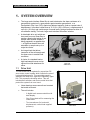
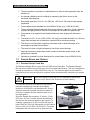
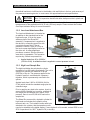
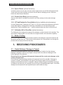
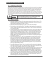
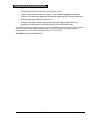
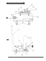
LG-8000 series INTERFACE SHEAR BOX Operators Manual Version 1.0 Durham Geo Slope Indicator 2175 West Park Court Stone Mountain, GA 30087 USA Telephone: 800-837-0864 or +1.770.465.7557 Fax: 770.465.7447 e-mail: [email protected] www.DurhamGeo.com LG-8000 series INTERFACE SHEAR BOX Disclaimer All information, illustrations, and specifications included in this manual are current as of the date of publication. Durham Geo Slope Indicator reserves the right to make changes at any time without notice. As believers in the continuous improvement process, we encourage our customers to comment on our goods and services and work with us in developing better solutions. IMPORTANT – Read & Save these instructions Before beginning installation procedures, these Installation and Operating Instructions should be studied carefully. Doing so will make installation easier and help you in the future if you have questions. The installation and operation should also be in accordance with local regulations and accepted codes of good practice. Call Durham Geo Slope Indicator if you have any questions; when you call you will need the model and serial numbers. Frame Model #: LG-8000 Unit Name: ______________ Frame Serial #: ______________ Unit Serial #: ______________ Sold By: ___________________ Sold By: ___________________ Date Purchased: _____________ Date Purchased: _____________ Unit Name: ______________ Unit Name: ______________ Unit Serial #: ______________ Unit Serial #: ______________ Sold By: ___________________ Sold By: ___________________ Date Purchased: _____________ Date Purchased: _____________ The model and serial numbers for the frame and readout are listed on the side and back of the equipment, respectively. You will need these numbers if you call DGSI for service or support. We can be reached between 8:00 am and 5:00 pm Eastern Standard Time (EST) at: Telephone: 1-800-837-0864 (outside Georgia, USA) (770) 465-7557 (inside Georgia, USA ) Fax: (770) 465-7447 Version 1.0 Confidential © 2012 Durham Geo Slope Indicator Page 2 of 40 LG-8000 series INTERFACE SHEAR BOX Table of Contents IMPORTANT SAFETY INSTRUCTIONS ................................................................................................... 5 1. SYSTEM OVERVIEW .......................................................................................................................... 6 1.1 1.2 1.2.1 Drive Unit ..................................................................................................................................... 6 Sample Boxes and Options ......................................................................................................... 7 Standard Sample Load Box ..................................................................................................................... 7 NOTICE: .................................................................................................................................................. 7 NOTICE: .................................................................................................................................................. 8 1.2.2 1.2.3 1.2.4 1.2.5 1.2.6 1.2.7 1.3 1. Low Load Attachment Box ....................................................................................................................... 8 High Load Sample Box ............................................................................................................................ 8 Spacer Blocks (optional accessory) ......................................................................................................... 9 Porous Stone Block (optional accessory) ................................................................................................ 9 LDT and Readout for Consolidation (factory installed optional accessory) .............................................. 9 Calibration Kit for Shear Box (optional accessory) .................................................................................. 9 Before Testing ............................................................................................................................. 9 RECEIVING PROCEDURES ............................................................................................................... 9 2.1 Onsite Delivery / Damage in Transit ............................................................................................ 9 2.2 Unpacking / Inspection .............................................................................................................. 10 NOTICE: ................................................................................................................................................ 10 2.3 Initial Assembly .......................................................................................................................... 10 3. GETTING STARTED ......................................................................................................................... 14 3.1 Learn Your Machine ................................................................................................................. 14 3.2 Applying a Load to High Load Shear Box.................................................................................. 17 NOTICE: ................................................................................................................................................ 17 CAUTION: ............................................................................................................................................. 17 3.3 Measuring the Normal Load ...................................................................................................... 17 4. OPERATION ...................................................................................................................................... 18 4.1 4.1.1 4.1.2 4.1.3 4.1.4 4.1.5 4.1.6 4.1.7 4.2 Operating Commands................................................................................................................ 18 Data Display ................................................................................................................................. 21 4.2.1 4.2.2 4.2.3 4.2.4 4.2.5 4.2.6 4.2.7 4.3.8 5. “Main” Screen ........................................................................................................................................ 18 “Fast Up” Screen ................................................................................................................................... 19 “Fast Down” Screen ............................................................................................................................... 19 “Move” Option Screen............................................................................................................................ 20 Command position: ................................................................................................................................ 20 Command Velocity: ............................................................................................................................... 20 Actual Position: ...................................................................................................................................... 20 Screen Description ................................................................................................................................ 21 Sensor Configuration Screen................................................................................................................. 21 Capture Screens .................................................................................................................................... 22 Communications .................................................................................................................................... 25 Software Installation ............................................................................................................................. 29 Individual Test Setup ............................................................................................................................. 31 How to customize your PC screen ......................................................................................................... 32 Displaying Your Results......................................................................................................................... 33 APPLYING NORMAL LOADS........................................................................................................... 34 CAUTION: ............................................................................................................................................. 34 5.1 Preparing the Sample ................................................................................................................ 34 5.2 Attaching the Membrane............................................................................................................ 35 5.3 Preparing the Soil ...................................................................................................................... 35 5.4 Adjusting the Shear Box ............................................................................................................ 36 5.5 Setting the "Home" / "0" Position ............................................................................................... 36 5.6 Checking the Limit Switches ...................................................................................................... 36 Version 1.0 Confidential © 2012 Durham Geo Slope Indicator Page 3 of 40 LG-8000 series INTERFACE SHEAR BOX CAUTION: ............................................................................................................................................. 36 5.7 Measuring the Normal Load ...................................................................................................... 36 6. MAINTENANCE ................................................................................................................................. 37 6.1 6.2 6.3 6.4 7. Daily ........................................................................................................................................... 37 Monthly ...................................................................................................................................... 37 Calibration .................................................................................................................................. 38 Verification ................................................................................................................................. 39 TROUBLESHOOTING ....................................................................................................................... 39 7.1 7.2 7.3 7.4 Adjusting the height of the Shear Box ....................................................................................... 39 Removing the gap between coupled units................................................................................. 39 Adjusting the LDT ...................................................................................................................... 39 Replacing the Fuse .................................................................................................................... 40 User Manual Updates Date 2012/01/05 Version 1.0 Name D. Loy Area Updated Approval Complete Confidential © 2012 Durham Geo Slope Indicator Page 4 of 40 LG-8000 series INTERFACE SHEAR BOX IMPORTANT SAFETY INSTRUCTIONS Your safety and the safety of others are very important. We have provided many important safety messages in this manual. Always read and obey all safety messages. This is the safety alert symbol. This symbol alerts you to potential hazards that can kill or hurt you and others. All safety messages follow the safety alert symbol and either the word “DANGER” or “WARNING” will identify potential hazard and will advise how to reduce the chance of injury and tell you what can happen if the instructions are not followed. Serious injured or could happen immediately if instructions are not followed. The wearing of safety glasses or goggles for eye protection should be mandatory when operating, calibrating, maintaining or otherwise using the equipment. Be sure to read and understand ALL operating procedures BEFORE using equipment. Unplug the machine from the electrical supply when not using the equipment. Avoid the pinch points when setting up and working with the equipment. Properly protect all electrical cords and machine cables from damage. Version 1.0 Confidential © 2012 Durham Geo Slope Indicator Page 5 of 40 LG-8000 series INTERFACE SHEAR BOX 1. SYSTEM OVERVIEW The Large-scale Interface Shear Box is used to determine the shear resistance of a geosynthetic against soil, a geosynthetic against another geosynthetic, or a Geosynthetic Clay Liner (GCL) against an adjacent material, under a constant rate of displacement. It provides a shear area of 12 x 12 in (305 x 305 mm), a displacement of up to 4 in (101 mm) and a wide range of normal loads. Optional accessories allow for consolidation testing. The basic, large scale Interface Shear Box includes: A detachable drive unit which can be moved from one Shear Box to another, allowing the testing of one sample while another sample is being prepared in a separate box — a significant benefit when soil saturation or sample set-up is a major time factor. An integral tank that allows immersion of the soil sample and the shear zone to emulate field conditions. A choice of a standard-load or high-load sample boxes and an optional low-load attachment for either. 1.1 LG-8000 series with High load attachment Drive Unit The horizontal load is regulated by a precision DC servo motor control system which controls the rate of horizontal displacement. This controlled speed is applied to the lower box, against the stationary upper box. This causes the shearing action. This unit includes limit switches, and motor control limits that protect the system from over travel. Linear bearings ensure smooth and constant horizontal movement. The unit includes: - A digital touch screen controller with data display. - One S-type load cell for measuring the Shear force. - Two transducers (for horizontal displacement, normal load supplied pressure). Version 1.0 Confidential © 2012 Durham Geo Slope Indicator Drive Unit Page 6 of 40 LG-8000 series INTERFACE SHEAR BOX The drive system is mounted on a wheeled frame to allow for easy separation from the sample box. An optional calibration device is offered for measuring the friction forces on the horizontal linear bearings. Removable upper box (12 x 12 x 4 in [305 mm x 305 mm x 102 mm]) for easy sample preparation. Forces applied by the standard box from 2000 lbf (9 kN) up to 14,400 lbf (64 kN). The air-operated bladder attachment fits onto the stationary upper box. It has a pressure regulator and gauge fixed to the side of the sample box to control the applied load. Compressed air is supplied to the bladder attachment via a single quick-disconnect fitting. The lower box (12 x 16 x 4 in [305 x 406 x 102 mm]) is moveable and built 4 in (102 mm) longer than the upper box to maintain a constant friction area during testing. The lower box is lined within a stainless steel water tank to allow the sample to be submerged to emulate field conditions. The lower box rides on high-load capacity, low-friction linear bearings. Upper and lower box clamps have radius corners to eliminate excess stress on the geosynthetic materials. Optional air-operated Low-load Attachment for normal loads of up to 2000 lbf (9 kN). 1.2 Sample Boxes and Options 1.2.1 Standard Sample Load Box The Standard Sample Box is a part of the LG 8000 series Shear Box. The Standard Sample Box has an air bladder built into the top of the unit as a standard feature. This unit is designed to operate at a maximum of 100 psi (690 kPa) of dry air. The pressure applied to the bladder is controlled by a ball valve and precision regulator which are permanently mounted to the sample box. NOTICE: Due to the weight of a full soil box, it is important to leave clear access to both sides of the Shear Box for safe handling. The Interface Shear Box is made from high quality materials including high strength aircraft-grade aluminum, HSLA steels, and stainless steel. All nonstainless materials are either anodized or plated for protection; hardware is either stainless steel or zinc chromate plated. Since the Sample Box measures 12 inch by 12 inch (305 mm x 305 mm), normal load can be estimated directly from the pressure applied to the sample. For example, a pressure of 60 psi (414 kPa) will apply a load of 8640 Ibf (38.4 kN) (theoretically) on the sample (60 psi x 144 in²) (414 kPa x 93,025 mm²). The actual load applied will vary and tend to be lower than the Standard Sample Box Version 1.0 Confidential © 2012 Durham Geo Slope Indicator Page 7 of 40 LG-8000 series INTERFACE SHEAR BOX theoretical load due to inefficiencies in the bladder, side wall friction in the box, and accuracy of the pressure-measuring device. In most cases, this approximation meets specifications. NOTICE: At full pressure, there is 14,400 Ibf (62 kN) of load on the Sample Box. It is imperative that all hold down clamps must be in place and secure. Durham Geo Slope Indicator can supply a calibration device that will allow a more accurate measurement of the applied load for a 12 inch (305 mm) sample. Please contact the Durham Geo Slope Indicator factory for more information. 1.2.2 Low Load Attachment Box The Low-load Attachment is intended as an addition to the standard-load or the high-load boxes. It fits on the upper, stationary half of the Shear Box assembly. Compressed air is supplied to the device by connecting an air line with a quick disconnect fitting. The air pressure is read to 0.1psi (0.7 kPa) on the touch screen data display located on the drive unit. A rolling diaphragm provides a constant, effective pressure area which is repeatable. This operation requires dry, filtered compressed air. Low Load Shear Box Applied loads from 20 to 2,000 lbf (100 N to 9 kN). A calibration chart is supplied to convert pressure to load. 1.2.3 High Load Sample Box The high load bridge has a hydraulic cylinder mounted to it as the loading mechanism. The unit is designed to operate at a maximum of 80 psi (550 kPa) of dry air. The pressure applied to the hydraulic system is controlled with a pressure regulator, which is permanently mounted to the system. Applied loads from 2,000 to 22,000 lbf (9 kN to 97 kN) which include the standard range plus the extended range. Prior to applying any load to the system, check to ensure that the sample box is secure, and that all four hinge pins and clamps are in place. At full pressure, there is over 22,000 lbf of load on the sample box. The Shear Box comes with a hydraulic cylinder for high loads and includes the hydraulic pump, reservoir tank, etc. The hydraulic hoses need to be High Load Shear Box attached to the cylinder, and the transducer cells need to be attached to the digital display. If more hydraulic oil is needed, contact DGSI or use SPX Corporation’s No. 9637 Hydraulic Oil (or similar). Version 1.0 Confidential © 2012 Durham Geo Slope Indicator Page 8 of 40 LG-8000 series INTERFACE SHEAR BOX 1.2.4 Spacer Blocks (optional accessory) To limit the amount of soil used, the lower and/or upper boxes may be filled with spacer blocks. These blocks are made of plastic and come with and without drainage grooves. Aluminum blocks are offered as an alternative. 1.2.5 Porous Stone Block (optional accessory) A porous stone block is available to prevent the soil from passing into the water drainage system. 1.2.6 LDT and Readout for Consolidation (factory installed optional accessory) A Linear Displacement Transducer (LDT) with 1-in (25.4 mm) travel and calibrated to the touch screen data display, is designed for measuring consolidation on low-load and high-load attachments. Factory installation only — must be ordered at the same time as the drive unit. 1.2.7 Calibration Kit for Shear Box (optional accessory) The Calibration kit is designed to measure the resistance to shear inherent to the machine. The set includes a loading plate, four load cells and, a digital indicator with summation capability. 1.3 Before Testing Prior to running a test, the operator should be familiar with making the connection between the Shear Box and the drive unit. This process is fairly simple, but it is beneficial to run through the process with an empty soil box the first time. 1. RECEIVING PROCEDURES 2.1 Onsite Delivery / Damage in Transit This product has been packed to insure that it arrives at your location free from damage. Damage in shipping is rare but may happen, always check for evidence of damage or loss before signing for any shipment. Do not sign for any shipment with apparent damage until the carrier notes damage on the receipt and signs same. Do not discard original packing materials until equipment has is fully operable. If damage to contents is evident, an examination and report by the transport agent must be requested. If damage is found after the carton is unpacked, notify the transport agent immediately to arrange an inspection and provide you necessary forms for filing a concealed damage report. Concealed damage must be reported to and inspected by the carrier within ten days. Version 1.0 Confidential © 2012 Durham Geo Slope Indicator Page 9 of 40 LG-8000 series INTERFACE SHEAR BOX 2.2 Unpacking / Inspection Remove the outer protective wrapping and the outside crate walls, being careful to not damage the Shear Box. Remove the supporting braces and steel banding from around the Shear Box. Closely inspect the frame and electronics for damage. Inspect all packages received and note any missing parts. Any problems should be reported to DGSI immediately at 770-465-7557. After unpacking the unit, place the drive unit and the Shear Box unit on a sturdy, level surface with access to 100 psi (690 kPa) air service and the appropriate AC supply voltage. Position the unit so that these connections and the corresponding hoses and cords are not in the normal working area. NOTICE: 2.3 Due to the weight of a full soil box, it is important to leave clear access to both sides of the Shear Box for safe handling. Always have two people handle the upper box due to weight. Initial Assembly Position the Shear Box (Figure 1) for easy operator access to the front of the unit. The Shear Box must be level in both the horizontal and vertical axes. If the box is not level, adjust Using the adjustable feet (Figure 1, item 9). Attach the positioning handle (Figure 2, item 1) on the drive unit carriage. Roll the drive unit up to the Shear Box. The heights of both machines are preset at the factory. Visually check that the alignment pins (Figure 2, item 5) and their mating holes are at the same height. Carefully push the drive unit onto the alignment pins (Figure 2. Item 5) in the back of the drive unit. At the same time, ensure that the drive unit tie rods are lined up with their mating points on the Shear Box (Figure 3, Item 1). If the box and drive unit do not go together smoothly, check that the surface is level. If this is determined not to be the problem, or if a level surface cannot be found, the height of the Shear Box may be adjusted. Refer to the troubleshooting section for instructions on adjusting the height of the Shear Box. (section 7.1) Place the clamp loop (Figure 1, ltem 1) on the Shear Box over the receiver (Figure 2, ltem 3) on the drive unit. Flip the toggle clamp (Figure 1, Item 1) back to secure the Shear Box to the drive unit. There is a toggle clamp on each side of the sheer box. Actuating the clamps should pull the drive unit tight to the Shear Box. Visually inspect the unit to ensure that there is no gap when the clamps are locked to ensure proper operation during loading. Refer to the troubleshooting (section 7.2) for instructions on removing a gap between the boxes. Screw the coupling nuts (Figure 3, ltem 1) on the drive unit tie rods onto the threaded end of the Shear Box tie rods. If the rods don't mate, pull the lower box toward the drive unit. If they are still misaligned, contact DGSI for further information. Install the LDT Stainless steel cover and Transducer Assembly (Figure 3, Item 5) on the Shear Box. Place the stainless steel LDT housing over the studs protruding from the right rear (facing the assembled unit) of the Shear Box and tighten it in place with the supplied wing nuts. Use caution when installing the LTD assembly; always depress the LDT shaft to insure it is not hitting the travel bracket after it is installed. (Figure 4, ltem 1). Check to be sure that the LDT is picking up on the travel bracket mounted to the lower plate of the Shear Box. If the LDT is not picking up on the travel bracket, refer to the troubleshooting section for adjustment instructions. Version 1.0 Confidential © 2012 Durham Geo Slope Indicator Page 10 of 40 LG-8000 series INTERFACE SHEAR BOX Connect the LDT cable to the drive unit (Figure 4, item 3). Check to ensure that the load cell (Figure 3, ltem 2) cable is plugged into the Data Collector. The cables are tagged with the channel number and the sockets are labeled. Plug the main power cord into the drive unit. Plug the main power cord into a grounded wall outlet. If a grounded outlet is not available, wire the machine in accordance with your local electrical code. The unit should now be ready for testing. If you encounter any problems or have any questions concerning the setup procedure please contact your local Durham Geo Slope Indicator representative or call our Stone Mountain office at 770-465-7557. See Pages 12 and 13 for Figure 1-4 Version 1.0 Confidential © 2012 Durham Geo Slope Indicator Page 11 of 40 LG-8000 series INTERFACE SHEAR BOX Fig 1 Fig 2 Version 1.0 Confidential © 2012 Durham Geo Slope Indicator Page 12 of 40 LG-8000 series INTERFACE SHEAR BOX Fig 3 Fig 4 Version 1.0 5 Confidential © 2012 Durham Geo Slope Indicator Page 13 of 40 LG-8000 series INTERFACE SHEAR BOX 3. GETTING STARTED 3.1 Learn Your Machine Over Travel Limit Switch Cross beam and loading rods Version 1.0 Confidential © 2012 Durham Geo Slope Indicator Page 14 of 40 LG-8000 series INTERFACE SHEAR BOX Handles to remove the upper box (4 each) Loading Platen (High Load) Top Membrane Grip for membrane to membrane testing Saturation water pan High Load Box High Load Controls Version 1.0 Confidential © 2012 Durham Geo Slope Indicator Page 15 of 40 LG-8000 series INTERFACE SHEAR BOX Regulator for controlling the normal load. Horizontal travel displacement transducer connection Gap adjustment screws (4 each) Version 1.0 High load attachment Horizontal travel displacement transducer Confidential © 2012 Durham Geo Slope Indicator High load pivot point Page 16 of 40 LG-8000 series INTERFACE SHEAR BOX 3.2 Applying a Load to High Load Shear Box The high load bridge has a hydraulic cylinder mounted to it as the loading mechanism. The unit is designed to operate at a maximum of 80 psi of dry air. The pressure applied to the hydraulic system is controlled with a pressure regulator, which is permanently mounted to the system. Prior to applying any load to the system, check to ensure that the sample box is secure, and that both hinge pins are in place. At full pressure, there is over 22,000 lbf of load on the sample box. All clamps and pins must be in place and secure. NOTICE: Normal loads are applied to the sample in the following way: Attach an airline with a ¼ inch female quick connect fitting to the hydraulic system. The orange switch on the regulator should be in the “OFF” position prior to connecting the air supply. With the air line installed, slowly turn the valve to the “ON” position. A black knob controls the direction of the loading platen. The platen does not move fast when the system is turned “ON”. This allows the operator to make adjustments to the platen and get use to the controls of the system. Once the operator has control of the system, testing can begin. Move the load platen in the downward direction. Manually line up the square loading platen as it enters the sample box. CAUTION: THIS IS A PINCH POINT. BE CAREFUL OF FINGERS. Once the load platen enters the sample box, it will apply a load to the sample. The load can be read on the digital indicator supplied. To increase the load on the sample, increase the compressed air supply pressure by using the pressure regulator. To decrease the load on the sample, decrease the compresses air pressure line.. 3.3 Measuring the Normal Load The sample box measures 12 inch by 12 inch (305 mm by 305 mm). The normal load is measured by using a pressure transducer in the hydraulic line and calibrating it with an EZ-Daq data collection unit. The digital indicator converts the line pressure from psi of hydraulic oil to pounds force. This load 2 is displayed on the indicator and can be divided by 144 inch in order to get your pounds per square in on the sample. Version 1.0 Confidential © 2012 Durham Geo Slope Indicator Page 17 of 40 LG-8000 series INTERFACE SHEAR BOX 4. OPERATION 4.1 Operating Commands Below is a screen shot of the controller. This controller is the “brains” of the machine. It controls all the parameters of the machine and the operational tests. These Include: Fast Up/Down (to quickly move the lower box toward or away from the drive unit prior to a test) Lower Box travel (in test mode) (LG8000E in), (LG8000M mm) Lower Box speed (in test mode) (LG-8000E In/mm), LG-8000 MM/min) Run Mode After powering up the machine, the LG-8000 Load Frame’s controller system will perform a selfcalibration before allowing user input. Move: Press move to access the screen to set test parameters. (See below) 4.1.1 “Main” Screen Zero: Sets the “Actual Position” to “0.00”. Actual Position: Travel distance from the “home, Zero” position. Touch to toggle between (mm) and (in). Fast Up: Accesses the screen for “Fast Up” controls. (See below) Fast Down: Accesses the screen for “Fast Down” controls. (See below) Stop: Stops all movement and testing of the lower box. Version 1.0 Confidential © 2012 Durham Geo Slope Indicator Page 18 of 40 LG-8000 series INTERFACE SHEAR BOX 4.1.2 “Fast Up” Screen Fast Up: Sets the lower box to the fastest travel in the “test” direction. (toward the Drive Unit). Stop: Stops the lower box movement. Main: Returns to the “Main Screen”. 4.1.3 “Fast Down” Screen Fast Down: Sets the lower box to the fastest travel in the “Reverse” direction. Toward the “Home” “Zero” position. (away from the Drive Unit). Stop: Stops the lower box movement. Main: Returns to the “Main Screen”. Version 1.0 Confidential © 2012 Durham Geo Slope Indicator Page 19 of 40 LG-8000 series INTERFACE SHEAR BOX 4.1.4 “Move” Option Screen Command Position: User input: Desired travel distance. Command Velocity: User input: Desired lower box velocity. Home: Returns the lower box in Fast Reverse to the preset “Zero” “Home” position. Zero: Sets the “Actual Position” to “0.00”. Start: Starts the “Test” using the parameters set on this screen. Stop: Stops all movement of the lower box including any tests being run. Actual Position: Travel distance from the “Home”, Zero position. Main: Returns to the “Main Screen”. 4.1.5 Command position: The distance the user wants the lower box to travel. The value can be changed using the numerical keypad, which is displayed when the display box below the “Command Position” is touched. This can be a positive or negative number. Using a negative number will cause the lower box to retract toward the home position, away from the drive unit. Using a positive number; the lower box will move in the normal test direction, toward the drive unit. Acceptable values are between 0.1” (2.54mm) and 4.0” (101.6mm). 4.1.6 Command Velocity: The speed (velocity) required by the test parameters. This number must be a positive number and is entered using the numerical keypad, which is display when the display box below the “Command Velocity” is touched. Acceptable values are between .0001 (.00254mm) per minute and .200” (5.08mm) per minute. 4.1.7 Actual Position: The distance the lower box has traveled in relationship to the “Home” position. The “Home” position is set using the “Zero” function before the test has been started. Version 1.0 Confidential © 2012 Durham Geo Slope Indicator Page 20 of 40 LG-8000 series INTERFACE SHEAR BOX 4.2 DATA DISPLAY 4.2.1 Screen Description Sensor Display Panel — Home Screen Sensors attached to the Data Collector are calibrated to their respective channels. The positions of the sensors can be changed but should only be done by a calibration technician or the factory Main screen of touch panel (Up to 6 sensors). 4.2.2 Sensor Configuration Screen Monitor page showing all sensors Main screen used for reference only: Can not be used to capture data. Version 1.0 Confidential © 2012 Durham Geo Slope Indicator Page 21 of 40 LG-8000 series INTERFACE SHEAR BOX Touching in the middle of any sensor box opens an option box for various operations for that sensor. TARE: Used to reset a particular sensors value to 0.000 CONFIG: Press this to enter into the Calibration of the sensors. Note: The Configuration button can only be accessed on the monitor page. Complete Calibration Instructions are located later in the manual. HOME: Returns to the main screen. 4.2.3 Capture Screens The following Screens are accessed from the "Home" screen by selecting the test you will be running. The computer software (described later in the manual) is used to collect the data from each of these screens. Low “Normal” Test Screen: For running a low load on the sample when shearing an optional Interface Shear Box (LG11220) is required. Version 1.0 Confidential © 2012 Durham Geo Slope Indicator Page 22 of 40 LG-8000 series INTERFACE SHEAR BOX Mid Range "Normal" Load Test Screen This screen captures data when running a Shear test using the Midrange bladder. Captures: Travel Shear load Air pressure supplied to the cylinder in PSI or Kpa. (Pressure to load conversions is supplied with the calibration). Mid Range "Normal" Load Test Screen This screen is selected from the home page and captures data for the high loading up to 23,000 lb. Captures: Travel Shear load Normal Load in lbs, Kn. Version 1.0 Confidential © 2012 Durham Geo Slope Indicator Page 23 of 40 LG-8000 series INTERFACE SHEAR BOX Version 1.0 Confidential © 2012 Durham Geo Slope Indicator Page 24 of 40 LS-8000 series INTERFACE SHEAR BOX 4.2.4 Communications Connect the Ethernet cable () to the USB/Ethernet adaptor ().Plug the Adaptor into the computer’s USB port (). NOTE: Uses a standard cat-5 Ethernet cable (1). The computer should recognize the new hardware and start loading software and drivers automatically. If asked to locate the drivers manually, place the CD with the drivers into the drive and follow instructions on the screen. Note: The next few pages describe how to configure the IP address on the USB/Ethernet adaptor. Version 1.0 Confidential © 2012 Durham Geo Slope Indicator Page 25 of 40 LS-8000 series INTERFACE SHEAR BOX After installing the USB driver, change the IP address to enable communications between the EZ-DAQ unit and EZ-DAQ-Soft software. Left-click on “Start”. Right-click on “My Network Places”. Left-click on “Properties”. Version 1.0 Confidential © 2012 Durham Geo Slope Indicator Page 26 of 40 LS-8000 series INTERFACE SHEAR BOX Right-click on the newly-installed USB device. Left-click on “Properties”. Note: the description will mention that it is a USB Ethernet Adaptor. Left-click on “Internet Protocol”. Left-click on “Properties”. Version 1.0 Confidential © 2012 Durham Geo Slope Indicator Page 27 of 40 LS-8000 series INTERFACE SHEAR BOX Select “Use the following IP address” Type in the following: 10.11.12 46 255.255.255.0 Click “OK”. Close all screens. The communications set up is now complete. Version 1.0 Confidential © 2012 Durham Geo Slope Indicator Page 28 of 40 LS-8000 series INTERFACE SHEAR BOX 4.2.5 Software Installation Insert CD and open the software installation folder and doubleclick “Setup.exe”. Follow instructions on the screen. Setup will create a directory. Select “Next”, to continue or click on “Browse”, to install the software in another directory. Note: User must have administrative rights to create files and directories. Once installation is complete, the program will be located under: Start/All Programs. Version 1.0 Confidential © 2012 Durham Geo Slope Indicator Page 29 of 40 LS-8000 series INTERFACE SHEAR BOX Launch the program via: Start/All Programs. The main screen will appear. Notice “Frame 6” is highlighted. This gives the user access to information on the right. The user can now enter sample interval information, test comments, etc. for test #6. Columns and headers can be user customized. Version 1.0 Area will be grayed-out until a “frame” is selected. Confidential © 2012 Durham Geo Slope Indicator Page 30 of 40 LS-8000 series INTERFACE SHEAR BOX 4.2.6 Individual Test Setup The heart of EZ-DAQ-Soft™ is the test screen, which allows the user to select the test on which the data will be captured. Select the test first. Select Test: The user first selects the test which corresponds to the sensors for that particular test. This highlights the frame fields which can be altered for each test. Data File Name: Enter the file name where the data for that test will be stored. A Windows tab on the far-right allows navigation thru the directory structure to the desired area for data storage. Test Comments: Text entered here will be saved along with test data. Sampling Intervals: Select the interval to change the sampling rate. Intervals can be added with the “insert” button and removed with the “delete” button. Note: When changing “Number of Samples” and “Sampling Interval”, be sure to click the “Modify” button to save the changes. Start Collection: Starts data collection for the highlighted test only. Each test must be highlighted and “Start Collection” must also be selected for data collection to begin. Note: The area on the right side of the screen will be grayed-out when the “Start Collection” button is pressed and no modifications can be made to that test when data collection is in progress. The screen will no longer be grayed-out once the test sampling period is complete. Tip: Make a note of defaults so you will have them in case of power loss. Version 1.0 Confidential © 2012 Durham Geo Slope Indicator Page 31 of 40 LS-8000 series INTERFACE SHEAR BOX 4.2.7 How to customize your PC screen Customize for your test names. Descriptions can be changed in the EZ-DAQ.ini file. C:\DGSI\EZ-DAQ\EZ-DAQ\EZ-DAQ.ini [Proface Setup] IPAddress=10.11.12.42 UDPPort=1024 ReadingStartMemAddress=100 RangesStartMemAddress=200 NumSensors=24 ColHeader0="" ColHeader1="Travel" ColHeader2="Load" ColHeader3="PSI" ColHeader4="Grapes" ColHeader5="Test Time" RowHeader0="Consol" RowHeader1="Triaxial" RowHeader2="CBR" RowHeader3="LBR" RowHeader4="Test 5" RowHeader5="Test 6" The illustration above shows how the PC software can be customized to match your company’s particular test names in your lab. This is located in C:\DGSI\EZ-DAQ\EZ-DAQ\EZ-DAQ.ini. The *.ini file is easily editable and can be opened with notepad or any other similar text editor. Note: It is always a good idea when dealing with *.ini files to make a backup copy before making changes to the file. Version 1.0 Confidential © 2012 Durham Geo Slope Indicator Page 32 of 40 LS-8000 series INTERFACE SHEAR BOX 4.3.8 Displaying Your Results When “Start Test” begins, EZ-DAQ-Soft™ creates a file in the C:DGSI\EZDAQ\Data\ Directory. To open the files simply click on it. The computer will ask for a program to associate with it. Select “Notepad” from the list. Note: Headers will be “tabbed” over a space. This makes it possible to import delimited data into a spreadsheet program. See next page for spreadsheet example. Version 1.0 Confidential © 2012 Durham Geo Slope Indicator Page 33 of 40 LS-8000 series INTERFACE SHEAR BOX 5. APPLYING NORMAL LOADS The sample box has an air bladder built into the top of the unit as a standard feature. This unit is designed to operate at a maximum of 100 psi (690 kPa) of dry air. The pressure applied to the bladder is controlled by a ball valve (Figure 1, ltem 2) and precision regulator (Figure 1, ltem 3) which are permanently mounted to the sample box. (Refer to Figures 1-4) Prior to applying any air to the sample box, check to ensure that the top is secure on the sample box. At full pressure, there is 14,400 Ibf (62 kN) of load on the sample box. All clamps (Figure 1, ltem 4) and hold downs (Figure 1, ltem 5) must be in place and secure. CAUTION: Do not attempt to adjust the regulator above 100 psi (690 kPa). The sample box top has a built-in pressure relief valve (Figure 1, ltem 6) that vents at 105psi (723 kPa). Removal or adjustment to the pressure relief voids all warranties and may cause serious injury to operators or extensive damage to the equipment. Normal loads are applied to the sample in the following way: Prior to applying pressure to the sample box, check that all hold down bolts and clamp knobs are installed and secure. Failure to do so can result in damage to the equipment or injury to the operator. Never apply pressure to the bladder without a sample or sample facsimile in the sample box. Failure to comply with this requirement will result in explosive failure of the bladder and may result in damage to the equipment or injury to the operator. Attach a ¼ inch airline to the fitting (Figure 1, item 7) going into the brass valve attached to the regulator. Caution: Make sure that the valve is in the "Off position (handle perpendicular to the valve body) prior to connecting the air supply. (Refer to Figures 1-4) With the air line installed, slowly turn the valve to the "ON" position. Insure the Regulator is turned "Counter clockwise" to the “NO” pressure position. 5.1 Adjust the regulator to the appropriate pressure for the desired load. For further information regarding this adjustment, refer to the "Adjusting the Shear Box" section of the manual. Preparing the Sample This section describes the appropriate method for removing the sample box, attaching the geosynthetic to the box for testing and placing the sample box in the Shear Box unit. This section does not address soil preparation, compaction, selection of membrane or other nonmachine specific issues. It is up to the user to determine the appropriate testing methodology for their customers and situation. If there are any equipment related questions, please contact the Durham Geo Slope Indicator technical support staff. To prepare the sample box for receiving the sample: Before removing the upper box, use a thickness gauge or sample of the material to be tested to adjust the clearance between the upper and lower boxes. Use the sample box adjusting bolts (Figure I, ltem 8) to set this height. (Refer to Figures 1-4) Version 1.0 Confidential © 2012 Durham Geo Slope Indicator Page 34 of 40 LS-8000 series INTERFACE SHEAR BOX Remove the sample box from the Shear Box unit by loosening the 4 hold-down clamps (Figure 1, Item 5) and pivoting them out of the way. (Refer to Figures 1-4) Take care when removing the sample box as it is quite heavy. Place the sample box on a level surface for sample preparation. Loosen the hand knobs on the top of the sample box. Completely remove the knobs on the fixed studs. Lift the top off using the handles mounted on the unit. Do not lift the top by the gauge, regulator or pressure relief valve. The sample box is now ready for sample preparation. 5.2 Attaching the Membrane The geosynthetic membrane is attached to the bottom sample box when performing membrane to soil testing. The top and bottom box clamps are both used when performing membrane to membrane testing. or both. Included with the Shear Box unit is a stainless steel template supplied to facilitate cutting out the membrane to fit in the geotextile clamp. To attach a membrane to the lower box clamp: Cut your membrane to size. The maximum recommended width is 12 inch (305 mm). It is also recommended that the length of the membrane be approximately 22 inch (560 mm) to accommodate attaching to the lower box clamp. Using the cut out template, cut the membrane to fit the clamps. Loosen the nuts or the bolt enough to provide the appropriate gap for the membrane. Place the membrane through the lower box clamp plate and tighten the clamp. To perform membrane to membrane testing; use of the upper box clamp will be necessary. Place the box in place on the Shear Box unit and adjust the gap between the lower box and the upper box using the gap adjustment screws on the Shear Box unit to accommodate 2 membranes. The gap should be adjusted to leave approximately .010 inch (0.2 mm) of clearance between the upper box and the membrane. Place the unattached end of the membrane through the upper box clamp and retighten. 5.3 Preparing the Soil As previously mentioned, sample preparation is specific to the material being tested and customer requirements. Durham Geo Slope Indicator offers accessories to facilitate sample preparation. For tests that do not require the sample boxes be full of soil, we offer PVC spacers for use in reducing the overall thickness of soil required. These blocks come in 12 x 16 inch (305 x 406 mm) dimensions for the lower box and 12 x 12 inch (305 x 305 mm) dimensions for the upper box. In cases where the lower box sample needs to be 12 x 12 inch, we offer an aluminum spacer that measures 4 x 12 inch (102 x 305 mm). This spacer can also be used to help eliminate soil extrusion in the uncovered area of the lower box during testing. Sample preparation can and will take a considerable amount of time. Having the appropriate tools and written procedures will simplify preparation and reduce the amount of time spent on this process. Version 1.0 Confidential © 2012 Durham Geo Slope Indicator Page 35 of 40 LS-8000 series INTERFACE SHEAR BOX A sample preparation table with solid wood or composite top makes an excellent work surface for sample cutting and trimming. 5.4 Adjusting the Shear Box There are several adjustments that can be made by the user to ensure proper operation of the Shear Box. If you have further questions about any of the following adjustments, please contact the factory. 5.5 Setting the "Home" / "0" Position The amount of travel available for a test is controlled by the position of the hand wheel in relation to the limit switches. To adjust the travel, use the following steps: (Refer section 4. Operation) Be sure the unit is "ON". After the controller has completed the startup procedure, determine which direction the box needs to be moved. Note: Do not adjust the travel of the box with the sample in place. If the sample has been installed in the Shear Box unit and the Shear Box unit is coupled to the drive unit, you will apply a shear load to the sample. Use the "F-FWD" or "F-REV” functions to move the hand wheel into the appropriate position. Press the "ZERO" function to establish this point as the new "Zero" or "Home” position. 5.6 Checking the Limit Switches Prior to running a test, it is advisable that the limit switch operation be checked. The limit switches provide a safety system to prevent over travel of the Shear Box. It is advisable that the limit switches be checked daily to ensure proper operation. (Refer Section 4) CAUTION: Improperly operating limit switches can and will result in damage to the equipment. Checking the limit switches involves using the drive unit. Do not perform this check with a sample installed. The limit switches may be checked by: Check that the unit is "ON". Check that the hand wheel is not resting on either limit switch. If the hand wheel is resting on a limit switch, use the controller to move the hand wheel away from the limit switches. With the hand wheel between the limit switches, move the unit with the "F-Fwd" function. While the unit is moving, manually depress the front limit switch. The unit should stop and the controller should display the message "Upper Limit Reached". Press “STOP” to acknowledge the limit message. Repeat this procedure by using the "F-Rev" function. 5.7 Measuring the Normal Load Since the sample box measures 12 inch by 12 inch (305 mm x 305 mm), normal load can be estimated directly from the pressure applied to the sample. For example, a pressure of 60 psi Version 1.0 Confidential © 2012 Durham Geo Slope Indicator Page 36 of 40 LS-8000 series INTERFACE SHEAR BOX (414 kPa) will apply a load of 8640 Ibf (38.4 kN) (theoretically) on the sample (60 psi x 144 inch²) (414 kPa x 93,025 mm²). The actual load applied will vary somewhat and tend to be lower than the theoretical load due to inefficiencies in the bladder, side wall friction in the box, and accuracy of the pressure-measuring device. In most cases, this approximation is accurate enough. If a more accurate measurement of the applied load, Durham Geo Slope Indicator can supply a calibration device that will correlate pressure readings to exact loads for a 12 inch (305 mm) sample. Please contact the factory for more information. Durham Geo Slope Indicator strongly recommends calibration of the Shear Box prior to use. Calibrating the device will provide a better understanding of the side wall friction and other conditions in the box that cause a deviation from the "ideal" performance. Additionally, calibration will give more accurate readings and help in interpreting results. 6. MAINTENANCE The LG-8000 will provide its best service if regular maintenance is performed on the unit. While the drive controls and instrumentation are solid state electronics and need little care, the actual drive train and carriage require periodic cleaning and lubrication. The following items should be addressed regularly: 6.1 Daily Check all external cables and connections for integrity. Repair or replace any damaged electrical components. Wipe any standing water off the unit. Remember, this is an electronic device. Care should be taken to keep the electronics dry and clean. Clean any soil that has spilled from the sample box. Check that all clamp bolts, hold downs, material clamps, etc. are in good operating condition and are fully functional. Replace any damaged mechanical components. 6.2 Monthly Lubricate the main carriage bearings through the zerk (grease) fitting located at the back of the Shear Box unit near the drain plug for the moisture box. Use a high pressure bearing grease. Contact the factory for details. Check the bronze piston for damage and lubrication. Lubricate with high pressure grease as necessary. Check the moisture box for leaks. Repair as necessary. Lubricate all threads with light machine oil (WD-40) to prevent galling. Version 1.0 Confidential © 2012 Durham Geo Slope Indicator Page 37 of 40 LS-8000 series INTERFACE SHEAR BOX 6.3 Calibration The Load Frame is calibrated before it leaves the factory. The calibration certificate is enclosed with the machine. If on-site calibration is required, the enclosed certificate cannot be used as a replacement. In most instances a recalibration is not required. It is good practice to have the machine calibrated on a minimum two year rotation. If tests are being run per ASTM standards then it is required to have the Load Frame calibrated every (12) months. Only a certified calibration technician should calibrate the LG8000. Password to enter the Calibration Screen is “2175”. To enter Calibration screen press here and enter password 2175 Version 1.0 Confidential © 2012 Durham Geo Slope Indicator Page 38 of 40 LS-8000 series INTERFACE SHEAR BOX 6.4 Verification To verify the normal load or assess bearing friction, contact Technical Support at Durham Geo Slope Indicator for the procedure and other instructions. 7. TROUBLESHOOTING 7.1 Adjusting the height of the Shear Box Roll the drive unit up to the Shear Box. Using a pair of adjustable wrenches or 3/4 in open-end wrenches, adjust the legs on the Shear Box until the unit is level with the drive unit and the two units mate. This adjustment should only have to be made once. If using multiple Shear Boxes check and adjust each unit in the location it will be used. Once the units are adjusted, they should fit together with very little force. If you still have problems mating the boxes and the heights are adjusted, apply pressure next to the handle with your foot. Moderate pushing at this point should allow the units to mate. If this does not work, check for interference of cables, soil, or other materials. If you still have difficulty mating the boxes, contact Durham Geo Slope Indicator for further assistance. Hint: Avoid adjusting the height of the drive unit. This height should be constant to allow for interchangeability between Shear Boxes. 7.2 Removing the gap between coupled units If there is a gap between the units when the clamps are locked, adjust the U-bolt on the clamp. This is done by loosening the appropriate nuts and shortening the extension on the U-bolt. If it becomes necessary to adjust the U-bolt, please contact the factory as this is an indication there may be a more serious problem with the unit. 7.3 Adjusting the LDT If the LDT is used on different boxes, it may need to be adjusted to pick up the travel bar correctly. This adjustment requires the use of a 5/32 in Allen wrench. Mount the LDT to the side of the Shear Box. (Note: This adjustment should only be made with the unit coupled and the Shear Box in the start position.) Using the Allen key, loosen the black socket head cap screw on the side of the LDT bracket. Gently pull the LDT into position by grasping the end of the LDT through the open end of the LDT bracket. Watch the LDT tip through the slot in the side of the bracket and position the tip against the travel bracket. Tighten the black screw when the tip is in position. Version 1.0 Confidential © 2012 Durham Geo Slope Indicator Page 39 of 40 LS-8000 series INTERFACE SHEAR BOX 7.4 Replacing the Fuse The fuse for the Drive Unit is located in the main power connector on the side of the unit. Unplug the unit. Using a screwdriver or fingernail, lift up on the tab on the fuse holder. Remove the old fuse. Replace with the appropriately-sized 5 A fuse. Replace the fuse holder. Any problems not covered in this manual or questions on the setup or operation of this unit, please contact Durham Geo Slope Indicator. Version 1.0 Confidential © 2012 Durham Geo Slope Indicator Page 40 of 40