1
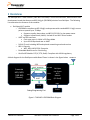
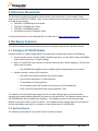
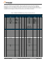
TWR-WIFI-GS1500M User’s Manual Rev. 1.0 Freescale Semiconductor Inc. TWRWIFIG1011MIUM Contents 1 Overview ......................................................................................................................................................3 2 Reference Documents ..............................................................................................................................4 3 Hardware Features ...................................................................................................................................4 3.1 GainSpan GS1500M Module ........................................................................................................................................... 4 3.2 System Power ....................................................................................................................................................................... 4 3.3 Special I/O, access headers, etc..................................................................................................................................... 5 3.4 LED, Switches and Buttons ............................................................................................................................................. 5 3.5 Elevator Connections ........................................................................................................................................................ 5 4 Jumper Table ..............................................................................................................................................8 Revision History Revision 1.0 TWRWIFIG1500MUM Date Sept 2012 Changes Initial Release TWR-WIFI-G1500M User’s Manual Page 2 of 8 1 Overview The GainSpan Wi-Fi Tower Module (TWR-WIFI-GS1500M) is a low-cost evaluation, demonstration and development board that features an 802.11b/g/n (GS1500M) solution from GainSpan. The following list summarizes the features of the modules: GainSpan Wi-Fi module o GS1500M is compliant to 802.11b/g/n and operates with standard 802.11 b/g/n access points at speeds up to 72 Mbps Supports standby, deep-sleep, and 802.11 PS-POLL for low power states Supports Infrastructure, Adhoc, Limited AP and Wi-Fi Direct modes o UART and SPI interfaces Clock rates up to 1.4 MHz in SPI Slave Mode Up to 921.6 kbps baud rate on UART o Full Wi-Fi stack including WPS and optional networking stack and services o 802.11i Security WEP, WPA, WPA2-PSK, Enterprise o Embedded Web Server for Provisioning o Certified RF Module: FCC/IC, ETSI, RoHS, Compliant with JAPAN regulatory A block diagram for the GainSpan module Based Tower is shown in the figure below. Antenna 3.3V HOST_WAKEUP Freescale MCU/MPU TWR BRD (Master) GPIO28 RESET SPI UART SPI UART SSPI UART GainSpan Low Power Wi-Fi Module (SPI Slave) MSPI RS232 Debug/Programming Port FLASH Figure 1. TWR-WIFI–GS1500M Block Diagram TWRWIFIG1500MUM TWR-WIFI-G1500M User’s Manual Page 3 of 8 2 Reference Documents The documents listed below should be referenced for more information on the Freescale Tower system and the TWR-WIFI-G1500M. Refer to http://www.freesale.com/tower for the latest revision of all Tower documentation. TWR-WIFI- GS1500M Quick Start Guide TWR-WIFI- GS1500M Lab Tutorial TWR-WIFI- GS1500MSchematics GainSpan Serial to Wi-Fi Adapters Guide For technical documents on the GainSpan Wi-Fi module refer to http://www.gainspan.com 3 Hardware Features This section provides more details about the features and functionality of the TWR-WIFI Module. 3.1 GainSpan GS1500M Module GainSpan module is a highly integrated ultra low power Wi-Fi module that contains the following: Contains media access controller (MAC), baseband processor, on-chip flash memory and SRAM, and a network processor in a single package. Built in certified PCB trace antenna or external Antenna and on board regulators, 32 KHz & 44 MHz crystal circuitries. o The GS1500M has capability of up to 14dBm (typical) output power at the antenna Module includes a variety of I/O interfaces: o Two UART with optional hardware flow control support o Two SPI block with Master or Slave Operation o I2C with Master or slave operation o Two low-power 10-bit ADC capable of running at up to 32 Ksamples/Sec., o GPIO’s, and LED Drivers/GPIO with 20mA capabilities, JTAG The Module carries on-board single supply monitor for under voltage supply and on-board 1.8V regulator with enable/disable capabilities for power critical applications. For additional details refer to the GS1500M data sheet available from GainSpan. The module connects to the Freescale Tower platform using either UART or the SPI interface. The module firmware supports basic AT command set and has the network stack built in so the driver is bare metal driver for the K60 MCU. 3.2 System Power The module is powered by 3.3V from the Primary Elevator connector. TWRWIFIG1500MUM TWR-WIFI-G1500M User’s Manual Page 4 of 8 3.3 Special I/O, access headers, etc. The firmware on the GainSpan module runs directly from the on-board flash on the module. To allow for updating of the program on the flash, the tower module incorporates a UART serial interface for programming purposes. This interface is brought out to a standard RS232 DB9 connector via a RS232 transceiver. In addition to the serial interface, a switch is also provided on the board to put the module in programming mode. 3.4 LED, Switches and Buttons The tower modules contain various LEDs, switches and Buttons that perform different functions or provide status information. The table below provides a brief description of the each of them. Table 1. TWR-WIFI-GS1500M Switch/LED/Button Table Item SW2 Type Button Label Reset Description SW3 Button Alarm SW4 Button WPS Not used SW5 Button Factory Restore Not used D1, D4 D2, D3 LED LED LED LED Resets the module Alarm input to wake module up from deepsleep or standby power save state Power Indication SW controlled using AT command from Module 3.5 Elevator Connections The tower module features two expansion card-edge connectors that interface to Elevator boards in a Tower system: the Primary and Secondary Elevator connectors. The Primary Elevator connector, comprised of sides A and B, is utilized by the tower module, while the Secondary Elevator connector TWRWIFIG1500MUM TWR-WIFI-G1500M User’s Manual Page 5 of 8 only makes connections to ground (GND). Table 2 provides the pinout for the Primary Elevator Connector. An “X” in the “Used” column indicates that there is a connection from the TWR-WIFIGS1500M to that pin on the Elevator connector. An “X” in the “Jmp” column indicates that a jumper is available that can configure or isolate the connection from the Elevator connector. Table 2. TWR-WIFI-GS1500M Primary Elevator Connector Pin-out TWR-WIFI-G1011MI/GS1500M Primary Connector Side B Side A Pin # Name B1 5V B2 GND Ground B3 3.3V 3.3V Power B4 ELE_PS_SENSE B5 GND B6 Usage Pin # Name A1 5V X A2 GND Ground X X A3 3.3V 3.3V Power X A4 3.3V 3.3V Power X Used Jmp Usage Used Ground X A5 GND Ground X Ground MSPI_CLK X A6 GND SCL0 Ground X B7 GND SPI1_CLK / SDHC1_CLK B8 SPI1_CS1 / SDHC1_CS1 MSPI_CSx A8 SDA0 B9 SPI1_CS0 / SDHC1_CS0 MSPI_CSx A9 GPIO9 / CTS1 EXT_RESET X B10 SPI1_MOSI / SDHC1_CMD MSPI_DIN A10 B11 SPI1_MISO / SDHC1_D0 B12 ETH_COL A12 B13 ETH_RXER A13 ETH_MDC B14 ETH_TXCLK A14 ETH_MDIO B15 ETH_TXEN A15 ETH_RXCLK B16 ETH_TXER A16 ETH_RXDV B17 ETH_TXD3 A17 ETH_RXD3 B18 ETH_TXD2 A18 ETH_RXD2 B19 ETH_TXD1 A19 ETH_RXD1 A20 ETH_RXD0 A21 SSI_MCLK SSI_BCLK Ground X Ground X A7 MSPI_DOUT A11 Mechanical Key GPIO8 / SDHC_D2 GPIO7 / SD_WP_DET ETH_CRS B20 ETH_TXD0 ipB21 GPIO1 GPIO_RST B22 GPIO2 GPIO29 A22 B23 GPIO3 GPIO19 A23 SSI_FS B24 CLKIN0 A24 SSI_RXD B25 CLKOUT1 A25 SSI_TXD B26 GND AN7 A26 B27 A27 GND AN3 B28 AN6 A28 AN2 B29 AN5 A29 AN1 B30 AN4 A30 AN0 B31 GND DAC1 A31 B32 A32 GND DAC0 B33 TMR3 A33 TMR1 B34 TMR2 A34 TMR0 B35 GPIO4 DC_DC_CNTL A35 GPIO6 ALARM2 B36 3.3V PWM7 3.3V Power A36 3.3V PWM3 3.3V Power B37 TWRWIFIG1500MUM X Ground X Ground X X X A37 Jmp TWR-WIFI-G1500M User’s Manual X Page 6 of 8 X B38 PWM6 A38 PWM2 B39 PWM5 A39 PWM1 B40 PWM4 A40 PWM0 B41 CANRX A41 RXD0 UART0_TX X B42 CANTX A42 TXD0 TWR_UART0 X A43 RXD1 A44 TXD1 Ground X EXT_RESET X Ground X B43 1WIRE B44 SPI0_MISO SSPI_DOUT X B45 SPI0_MOSI SSPI_DIN X A45 GPIO B46 SPI0_CS0 SSPI_CS X X A46 GPIO B47 SPI0_CS1 SSPI_CS X X A47 GPIO B48 SPI0_CLK SSPI_CLK X A48 GPIO B49 Ground I2C_CLK X A49 GND B50 GND SCL1 A50 GPIO B51 SDA1 I2C_DATA A51 GPIO B52 GPIO5 ALARM1 A52 GPIO B53 USB_DP_PDOWN A53 B54 A54 GPIO USB_DM B55 USB_DM_PDOWN IRQ_H A55 USB_DP B56 IRQ_G B57 IRQ_F B58 IRQ_E B59 IRQ_D B60 IRQ_C B61 IRQ_B B62 IRQ_A B63 FB_ALE/FB_CS1_b B64 FB_CS0_b B65 GND B66 X GPIO28 X X GPIO28 X X GPIO28 X X GPIO28 X X USB_ID A57 USB_VBUS A58 TMR7 A59 TMR6 A60 TMR5 A61 TMR4 A62 RSTIN_b A63 RSTOUT_b A64 CLKOUT0 A65 GND FB_AD15 A66 FB_AD14 B67 FB_AD16 A67 FB_AD13 B68 FB_AD17 A68 FB_AD12 B69 A69 FB_AD11 B70 FB_AD18 FB_AD19 A70 FB_AD10 B71 FB_R/W_b A71 FB_AD9 B72 FB_OE_b A72 FB_AD8 B73 FB_D7 A73 FB_AD7 B74 FB_D6 A74 FB_AD6 B75 FB_D5 A75 FB_AD5 B76 FB_D4 A76 FB_AD4 B77 FB_D3 A77 FB_AD3 B78 FB_D2 A78 FB_AD2 B79 FB_D1 A79 FB_AD1 B80 FB_D0 A80 FB_AD0 B81 GND Ground X A81 GND Ground X B82 3.3V 3.3V Power X A82 3.3V 3.3V Power X TWRWIFIG1500MUM Ground X A56 TWR-WIFI-G1500M User’s Manual Page 7 of 8 X X 4 Jumper Table There are several jumpers provided for isolation, configuration, and feature selection. Refer to the following table for details. The default installed jumper settings are highlighted below. Table 3. TWR-WIFI-GS1500M Jumper Table Jumper SW1 Option Power Supply Input SW6 Mode Selection J1 Interrupt Selection J3 SPI/UART Selection1 J4 J5 J7 J8 J9 J11 J14 J15 GS1500M Reset Selection Slave SPI Port CS Selection UART Routing Selection Master SPI Port CS Selection Power Isolation and Current Measurement RS232 Transceiver Force-off UART CTS Isolation Setting ELEV PWR DC PWR RUN PRGM 1-2 3-4 5-6 7-8 1-2 2-3 1-2 2-3 1-2 2-3 1-2 2-3 1-2 2-3 1-2 2-3 ON Description Power from Tower System 3.3V Power from DC power jack (J2) GS1500M in standard "run" mode GS1500M in program mode Connect GS1500M interrupt to Tower IRQ_G (B56) Connect GS1500M interrupt to Tower IRQ_E (B58) Connect GS1500M interrupt to Tower IRQ_C (B60) Connect GS1500M interrupt to Tower IRQ_A (B62) Select SPI as serial interface Select UART as serial interface Connect GS1500M Reset to Tower GPIO9 (A9) No connection Connect GS1500M Reset to Tower RSTOUT (A63) Connect GS1500M Reset to Tower GPIO1 (B21) Connect Tower SPI0_CS0 to slave SPI CS on GS1500M Connect Tower SPI0_CS1 to slave SPI CS on GS1500M Connect GS1500M UART0 to on-board RS232/DB9 Connect GS1500M UART0 to Tower System Connect Tower SPI1_CS1 to master SPI CS on GS1500M Connect Tower SPI1_CS0 to master SPI CS on GS1500M Connect GS1500M power supplies to the 3.3V supply source Isolate GS1500M from power supplies. J11 can be used to measure the energy consumption of the VBAT, VDDIO, and EN_1V8 supplies to the GS1500M. RS232 transceiver operates in normal mode OFF RS232 transceiver forced off ON OFF Connect UART0_CTS from GS1500M to RS232 transceiver Disconnect UART0_CTS from RS232 transceiver ON OFF Note: 1. This jumper is not applicable with Serial to Wi-Fi firmware. It is applicable with IP-to-Wi-Fi firmware. TWRWIFIG1500MUM TWR-WIFI-G1500M User’s Manual Page 8 of 8