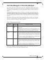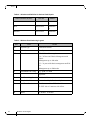
1
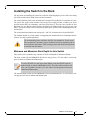
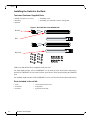
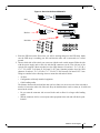
36 Port InfiniBand QDR Switch Platform Installation Guide PNs: MIS5025, MIS5030, MIS5035 Rev 1.8 www.mellanox.com Rev 1.8 NOTE: THIS HARDWARE, SOFTWARE OR TEST SUITE PRODUCT (“PRODUCT(S)”) AND ITS RELATED DOCUMENTATION ARE PROVIDED BY MELLANOX TECHNOLOGIES “AS-IS” WITH ALL FAULTS OF ANY KIND AND SOLELY FOR THE PURPOSE OF AIDING THE CUSTOMER IN TESTING APPLICATIONS THAT USE THE PRODUCTS IN DESIGNATED SOLUTIONS. THE CUSTOMER'S MANUFACTURING TEST ENVIRONMENT HAS NOT MET THE STANDARDS SET BY MELLANOX TECHNOLOGIES TO FULLY QUALIFY THE PRODUCT(S) AND/OR THE SYSTEM USING IT. THEREFORE, MELLANOX TECHNOLOGIES CANNOT AND DOES NOT GUARANTEE OR WARRANT THAT THE PRODUCTS WILL OPERATE WITH THE HIGHEST QUALITY. ANY EXPRESS OR IMPLIED WARRANTIES, INCLUDING, BUT NOT LIMITED TO, THE IMPLIED WARRANTIES OF MERCHANTABILITY, FITNESS FOR A PARTICULAR PURPOSE AND NONINFRINGEMENT ARE DISCLAIMED. IN NO EVENT SHALL MELLANOX BE LIABLE TO CUSTOMER OR ANY THIRD PARTIES FOR ANY DIRECT, INDIRECT, SPECIAL, EXEMPLARY, OR CONSEQUENTIAL DAMAGES OF ANY KIND (INCLUDING, BUT NOT LIMITED TO, PAYMENT FOR PROCUREMENT OF SUBSTITUTE GOODS OR SERVICES; LOSS OF USE, DATA, OR PROFITS; OR BUSINESS INTERRUPTION) HOWEVER CAUSED AND ON ANY THEORY OF LIABILITY, WHETHER IN CONTRACT, STRICT LIABILITY, OR TORT (INCLUDING NEGLIGENCE OR OTHERWISE) ARISING IN ANY WAY FROM THE USE OF THE PRODUCT(S) AND RELATED DOCUMENTATION EVEN IF ADVISED OF THE POSSIBILITY OF SUCH DAMAGE. Mellanox Technologies 350 Oakmead Parkway Suite 100 Sunnyvale, CA 94085 U.S.A. www.mellanox.com Tel: (408) 970-3400 Fax: (408) 970-3403 Mellanox Technologies, Ltd. PO Box 586 Hermon Building Yokneam 20692 Israel Tel: +972-4-909-7200 Fax: +972-4-959-3245 © Copyright 2011. Mellanox Technologies. All rights reserved. Mellanox®, BridgeX®, ConnectX®, InfiniBlast®, InfiniBridge®, InfiniHost®, InfiniRISC®, InfiniScale®, InfiniPCI®, PhyX® and Virtual Protocol Interconnect® are registered trademarks of Mellanox Technologies, Ltd. CORE-Direct and FabricIT are trademarks of Mellanox Technologies, Ltd. All other marks and names mentioned herein may be trademarks of their respective companies. 36 Port InfiniBand QDR Switch Platform Installation Guide 2 Mellanox Technologies Document Number: 3135 Rev 1.8 Table of Contents Table of Contents . . . . . . . . . . . . . . . . . . . . . . . . . . . . . . . . . . . . . . . . . . . . . . . . . . .3 List of Figures . . . . . . . . . . . . . . . . . . . . . . . . . . . . . . . . . . . . . . . . . . . . . . . . . . . . . .4 List of Tables . . . . . . . . . . . . . . . . . . . . . . . . . . . . . . . . . . . . . . . . . . . . . . . . . . . . . .5 About this Manual . . . . . . . . . . . . . . . . . . . . . . . . . . . . . . . . . . . . . . . . . . . . . . . . . .7 Intended Audience . . . . . . . . . . . . . . . . . . . . . . . . . . . . . . . . . . . . . . . . . . . .7 Related Documentation . . . . . . . . . . . . . . . . . . . . . . . . . . . . . . . . . . . . . . . .7 Document Conventions . . . . . . . . . . . . . . . . . . . . . . . . . . . . . . . . . . . . . . . . .7 Internally Managed vs. Externally Managed . . . . . . . . . . . . . . . . . . . . . . . . . . . . .9 Installing the Switch in the Rack . . . . . . . . . . . . . . . . . . . . . . . . . . . . . . . . . . . . .11 Minimum and Maximum Rack Depth for this Switch . . . . . . . . . . . . . . . . . .11 Installing the Switch in the Rack . . . . . . . . . . . . . . . . . . . . . . . . . . . . . . . . .12 Grounding the Switch . . . . . . . . . . . . . . . . . . . . . . . . . . . . . . . . . . . . . . . . . . . . . .19 Configuring the Switch for the First Time . . . . . . . . . . . . . . . . . . . . . . . . . . . . . .20 Unified Fabric Manager (UFM) . . . . . . . . . . . . . . . . . . . . . . . . . . . . . . . . . . . . . . .27 FabricIT . . . . . . . . . . . . . . . . . . . . . . . . . . . . . . . . . . . . . . . . . . . . . . . . . . . . . . . . . .28 Starting an SSH Connection to the Switch . . . . . . . . . . . . . . . . . . . . . . . . . . . . .30 Starting a WebUI Connection to the Switch . . . . . . . . . . . . . . . . . . . . . . . . . . . .31 Resetting the Switch . . . . . . . . . . . . . . . . . . . . . . . . . . . . . . . . . . . . . . . . . . . . . . .32 Mellanox Technologies 3 Rev 1.8 List of Figures Figure 1: Rack Rail Kit Parts MIS00083/85 . . . . . . . . . . . . . . . . . . . . . . . . . . . . . . . . . . . .12 Figure 2: Rack Rail Kit Parts MIS000079 . . . . . . . . . . . . . . . . . . . . . . . . . . . . . . . . . . . . .13 Figure 3: Installation Options Available for Short Switches . . . . . . . . . . . . . . . . . . . . . . . .14 Figure 4: Installation Options Available for Standard Length Switches . . . . . . . . . . . . . . .14 Figure 5: For Short Switches Which Side of the Rack Do You Want the Connectors ? . . .15 Figure 6: Making Room for the Power Cord . . . . . . . . . . . . . . . . . . . . . . . . . . . . . . . . . . . .16 Figure 7: Screwing on the Bracket . . . . . . . . . . . . . . . . . . . . . . . . . . . . . . . . . . . . . . . . . . .16 Figure 8: Screwing on the Rail . . . . . . . . . . . . . . . . . . . . . . . . . . . . . . . . . . . . . . . . . . . . . .17 Figure 9: Inserting the Caged Nuts . . . . . . . . . . . . . . . . . . . . . . . . . . . . . . . . . . . . . . . . . .17 Figure 10: Connect Bracket to Rack Vertical support . . . . . . . . . . . . . . . . . . . . . . . . . . . . .18 Figure 11: Externally Managed Management Interface . . . . . . . . . . . . . . . . . . . . . . . . . . .20 Figure 12: License Key Entitlement Number . . . . . . . . . . . . . . . . . . . . . . . . . . . . . . . . . . . .28 Figure 13: License Key Generation Form . . . . . . . . . . . . . . . . . . . . . . . . . . . . . . . . . . . . . .29 Figure 14: Reset Button . . . . . . . . . . . . . . . . . . . . . . . . . . . . . . . . . . . . . . . . . . . . . . . . . . . .32 4 Mellanox Technologies Rev 1.8 List of Tables Table 1: Revision History of this User’s Manual . . . . . . . . . . . . . . . . . . . . . . . . . . . . . . . . .6 Table 2: Reference Documents and Web Sites . . . . . . . . . . . . . . . . . . . . . . . . . . . . . . . . .7 Table 3: Switch Management by OPN . . . . . . . . . . . . . . . . . . . . . . . . . . . . . . . . . . . . . . . .9 Table 4: Switches and Rail Kits for Various Rack Depths . . . . . . . . . . . . . . . . . . . . . . . . .10 Table 5: Mellanox Part Numbering Legend . . . . . . . . . . . . . . . . . . . . . . . . . . . . . . . . . . . .10 Table 6: Serial Terminal Program Configuration . . . . . . . . . . . . . . . . . . . . . . . . . . . . . . . .21 Table 7: Configuration Wizard Session - IP Configuration by DHCP . . . . . . . . . . . . . . . .21 Table 8: Configuration Wizard Session - IP Zeroconf Configuration . . . . . . . . . . . . . . . . .23 Table 9: Configuration Wizard Session - Static IP Configuration . . . . . . . . . . . . . . . . . . .24 Mellanox Technologies 5 Rev 1.8 Revision History Table 1 - Revision History of this User’s Manual Revision 6 Date Details 1.8 November 2012 • Added Note to See “Installing the Switch in the Rack” on page 12.regarding lack of support for standard length switch installation with power side next to the vertical support • Added Figure 4 and Figure 5 and text regarding lack of support for Standard installation with the connector side deeper in the rack 1.7 April 2012 Fixed disclaimer typo Fixed TOC hierarchy 1.6 Sept. 2011 Changes to the Reset button section Removed 5031switch 1.5 May 2011 Added section on UFM 1.4 July 2010 Added files to change this into a book.Added last page with barcode 1.3 June 2010 Added “Getting the License Key” 1.2 May 2010 Added Note: ETH Ports Must be 10/100M 1.1 April 2010 Minor formatting 1.0 April 2010 Initial Release Mellanox Technologies Rev 1.8 About this Manual This manual provides installation and set-up instructions for the IS50XX series QSFP top of rack InfiniBand Switch Platform. Intended Audience This manual is intended for users and system administrators responsible for installing and setting up the switch platform. The manual assumes familiarity with the InfiniBand® architecture specification. Related Documentation The documentation set accompanying the QSFP Chassis InfiniBand Switch platform includes the following: Table 2 - Reference Documents and Web Sites Switch Firmware and Firmware Update Tools See http://www.mellanox.com/content/ pages.php?pg=management_tools&menu_section=34 Note that the Switch System described in this manual is based on Mellanox Technologies’ InfiniScale IV switch device. FabricIT TM Enterprise Fabric Management (EFM) Software User’s Manual Talk to your Mellanox representative for information regarding licensing and implementation of the FabricIT Enterprise Fabric Management Software System. See Document Conventions When discussing memory sizes, MB and MBytes are used in this document to mean size in mega bytes. The use of Mb or Mbits (small b) indicates size in mega bits. This symbol indicates a recommendation. This symbol indicates importatnt information for the user and installer. This symbol indicates a potential danger of damage to the hardware or software. Mellanox Technologies 7 Rev 1.8 This symbol indicates a potential danger of injury to users and / or installers and potential damage to the hardware or software. 8 Mellanox Technologies Rev 1.8 Internally Managed vs. Externally Managed The following table shows which switches come with a management CPU and which do not. Managed switches can be upgraded from simple chassis management to full fabric management by purchasing an additional license. For more information on buying a license see the user’s manual. Unmanaged switches are plug and play out of the box. All switches come with the latest firmware burned on the Flash. Update the firmware on unmanaged switches in-band only. When new firmware is available you will receive an email with the link to the Mellanox firmware download site. The download site has the Mellanox firmware tool package and full instructions for updating firmware. All managed switches have internal chassis management and can manage up to 108 nodes. FabricIT can support IB fabrics of up to 648 nodes. Managed switches need an initial configuration before they will start working. See Table 3 for details. Table 3 - Switch Management by OPN Family Managed / Unmanaged Management Connections IS5025 Unmanaged No Management Plug and play All firmware updates should be done in-band using Mellanox Firmware Management Tools. 12C port access using MTUSB-1 device is required for firmware updates if in-band burning is not possible. IS5030 Managed RS232 cable DB9 to RJ45 included in the box to connect to host PC for initial configuration of the switch. After initial configuration the switch can be managed through the Ethernet using a remote connection. This switch is capable of Fabric management for an unlimited number of nodes, with the purchase of Mellanox UFM. IS5035 Managed RS232 cable DB9 to RJ45 included in the box to connect to host PC for initial configuration of the switch. After initial configuration the switch can be managed through the Ethernet using a remote connection. This switch is capable of Fabric management for an unlimited number of nodes, with the purchase of Mellanox UFM. Should your unmanaged switch have CONSOLE, Ethernet, and USB connectors, they will not work. Only the I2C connector will work on unmanaged switches. Mellanox Technologies 9 Rev 1.8 Table 4 - Switches and Rail Kits for Various Rack Depths Switch S(Standard)/ B (Short) Rack Size Rail Kit # Short 50cm to 80cm MIS00008 3 Short 38cm to 50cm MIS00007 9 Standard 50cm to 80cm MIS00008 5 Table 5 - Mellanox Part Numbering Legend Place Field Decoder IS System Type InfiniScale Switch 50 Model Family FF Form factor 25 = 36 Ports Unmanaged 30 = 36 Ports and Chassis Management with Fabric Management up to 108 nodes 35 = 36 ports with chassis management and Fabric Management up to 2000 nodes C InfiniBand Port Config. Q= QDR, D= DDR - Separator P # of Power Supplies 0=0, 1=1, 2=2.... M Depth of the Unit S = standard depth, B = short depth Y Air Flow direction R= Connector side to PSU side airflow F= PSU side to Connector side airflow R 10 RoHS Mellanox Technologies C=RoHS5, X=RoHS6 Rev 1.8 Installing the Switch in the Rack The procedure for installing the switch in a full rack while bringing the power cord across along side of the switch can be found in the switch user manual. The switch platform can be rack mounted and is designed for installation in a standard 19” rack. The power side of the switch includes a hot-swap power supply module, a blank cover for an optional second PSU for redundancy, and a hot-swap fan tray. There are two possible air flow directions. Be sure that the switch air flow direction is compatible with your system, rack, and PSUs. The connector side of the switch has the QSFP ports, system LEDs, and management connection ports. The switch platform contains auto-sensing 100 - 240 VAC connections for all possible PSUs. The installer should use a rack capable of supporting the mechanical and environmental characteristics of a fully populated platform. The rack mounting holes conform to the EIA-310 standard for 19-inch racks. Take precautions to guarantee proper ventilation in order to maintain good airflow at ambient temperature. Cable routing in particular should not impede the air exhaust from the chassis. Minimum and Maximum Rack Depth for this Switch This switch can be installed in any standard 19”racks with depths of 380mm to 800mm. The short switch with the MIS000079 Rail kit can only go into a 19” rack whose vertical supports are between 380mm and 500mm apart. To use the IS50XX in a rack deeper than 500mm, order the IS50XX with the standard depth, or order the MIS000083 rail kit. The both of these solutions will allow you to install the switch in a 19” rack whose vertical supports are between 500mm and 800mm apart. The standard depth switch uses the MIS000085 rail kit for installation in a 19” rack whose vertical supports are between 500mm and 800mm apart. Mellanox Technologies 11 Rev 1.8 Installing the Switch in the Rack Tools and Customer Supplied Parts • Phillips Screwdrivers #1 and #2 • ESD strap • ESD mat • Grounding screw • Grounding wire sufficient to reach a valid ground. Figure 1: Rack Rail Kit Parts MIS00083/85 Bracket Rail Rail slide Make sure that the Rail kit is compatible with your rack. For short depth switches, rail kit # MIS00083 is to be used for racks from 50cm to 80cm deep, and rail kit # MIS00079 is to be used for racks from 38cm to 50cm deep including the iDataPlex rack. For standard depth switches rail kit # MIS00085 is to be used for racks from 60cm to 80cm deep. Parts included in the rail kit: • 2 rails • 2 rail slides • 2 brackets 12 Mellanox Technologies • 18 recessed flat head screws • 8 caged nuts • 8 pan head screws M6 Rev 1.8 Figure 2: Rack Rail Kit Parts MIS000079 Rail Bracket Rail slide 1. Place the ESD mat on the floor where you will be working and put on the ESD strap. Make sure the ESD strap is touching your skin and that the other end is connected to a verified ground. 2. Choose which side of the switch you want even with the rack vertical support. Either the side with the power supply units or the side with the IB connectors can be even with one of the vertical rack supports. Short switches have the OPN character -B and are 1.716” (1U) H x 17.17” W x16.84” D 43.6mm X 436.2mm X 427.7mm. Standard switches have the OPN character -S and are 1.716” (1U) H x 17.17” W x24.71” D 43.6mm X 436.2mm X 627.7 mm. Things to consider before choosing where to mount the rails and rail slides. • Air flow • Configuration of already installed equipment • Cable bending radius The distance between the rack and the door can be as little as 4 cm on one side of the rack and as much as 18 cm on the other side of the rack. Keep in mind that there can be as many as 36 cables connected to the switch. • Do you want the connector side recessed in the rack to allow for a larger cable bending radius? • Will the connector side be recessed past other equipment in the rack and will this be problematic? Mellanox Technologies 13 Rev 1.8 Figure 3: Installation Options Available for Short Switches Doors Doors Connector side Spine side 19" (482.6mm) 19" (482.6mm) Switch Switch Spine side Connector side Doors Doors Figure 4: Installation Options Available for Standard Length Switches 24.71” or 627.6mm deep Doors Doors Connector side Spine side 19" (482.6mm) 19" (482.6mm) Switch Spine side Doors Installation A Switch Connector side Doors Installation B Standard switches only support installation with the connector side of the switch near the rack door, as per installation B in Figure 4. 14 Mellanox Technologies Rev 1.8 Figure 5: For Short Switches Which Side of the Rack Do You Want the Connectors ? … … … . … … … . The figure above shows the power side next to the door and the connector side away from the door. This configuration has more room for the cables and a larger bending radius. This configuration is not supported for standard length switches (24.71” or 627.6mm deep). The figure below shows the connector side next to the door and the power side away from the door. This configuration may be necessary to conform to your rack configuration. … … … . … … … . 3. Screw the brackets onto the switch. Use the flat head screws to connect the bracket. There are two options for mounting the bracket. One option will place the switch even with the vertical support of the rack and the second option will recess the switch further into the rack. If you Mellanox Technologies 15 Rev 1.8 are using the second option insert the power cable before screwing the bracket to the vertical support. If you need to bring the Power cord from the other side of the rack, recess the switch and run the Power cord through the bracket, also using the slot in the rail slide. Go to “Passing the Power Cord From the Connector Side to the Power Side” on page 61 for detailed instructions on routing the power cord from the power side to the connector side. Figure 6: Making Room for the Power Cord Power cord Figure 7: Screwing on the Bracket Option A Option A puts the front of the switch ~5cm behind the rack vertical support Option B Option B puts the front of the switch even with the rack vertical support Place to put the power cable. Option A will require 3 flat head screws This configuration also allows you to put the power cord through the bracket. 16 Mellanox Technologies Option B will require 4 flat head screws Rev 1.8 The side of the switch with these brackets will be the side that is even with or very close to the vertical rack support. 4. Screw the rails onto the switch. Use 5 flat head screws to connect each rail to the switch. Figure 8: Screwing on the Rail 5 screws 5. Clip the 4 caged nuts into the holes in the rack you will be using to connect the rail slides. Check that both sides of the switch, left and right, are the same level in the rack. Figure 9: Inserting the Caged Nuts 20 The caged nuts are separated by a single space 6. Clip 4 more caged nuts into the holes in the rack you will be using to connect the brackets. Check that both sides of the switch, power side and connector side, are at the same level in the rack. 7. Using two of the bolts for each rail slide, install the rail slides. 8. Tighten the bolts to 9.2 Nm or 81.5 pound inches. If the power cable is on this side of the switch, feed the power cable into the slot in the rail slide before screwing it to the vertical support. Mellanox Technologies 17 Rev 1.8 Figure 10: Connect Bracket to Rack Vertical support 9. Place the four bolts for the caged nuts within reach. 10. Slide the switch into the rails. 11. Put the switch into place and screw the bolts into the nuts from step 6. If the power cable is on this side of the switch, feed the power cable into the slot in the bracket before screwing it to the vertical support.Tighten the bolts to 9.2 Nm or 81.5 pound inches. 12. Tighten all of the screws to 9.2 Nm or 81.5 pound inches. 13. Ground the switch 14. Plug in the power cables. 15. Check the Status LEDs and confirm that all of the LEDs show status lights consistent with normal operation. Warning: Any yellow status LEDs is cause for concern and must be dealt with immediately. It can take up to 5 minutes to boot up, during which time the status LED may indicate red. 16. You can start connecting all of the cables to the switch. 18 Mellanox Technologies Rev 1.8 Grounding the Switch Check to determine if your local or national electrical codes require an external ground to all IT components. If so, connect a ground wire to one of the casing screws and connect the other end to a valid ground. If you choose to not use the ground screw, make sure that the rack is properly grounded and that there is a valid ground connection between the chassis of the switch and the rack. Test the ground using an Ohm meter. Some national and/or local codes may require IT components to be bonded and externally grounded (not including the power cord ground). You must follow all national and local codes when installing this equipment. Mellanox Technologies 19 Rev 1.8 Configuring the Switch for the First Time Externally Managed (Unmanaged) Switches Unmanaged (Externally managed) switches, that is the IS5025 switches, do not get configured. On unmanaged switches, the CONSOLE, Ethernet, and USB connectors are not found and if existing do not work. Figure 11: Externally Managed Management Interface IS5025 I2C The unmanaged switches are Plug and Play and all firmware updates should be done in-band. The I2C connection should only be used if the firmware image was corrupted to the point that the regular firmware tools cannot successfully reburn the correct image. When you install the switch, it comes with the latest firmware burned on the board. You will not need to burn firmware unless you get notification from Mellanox that a newer version of firmware for your switch has been released. Managed (Internally managed) Switches 1. Connect the host PC RS232 connector to the CONSOLE port of the switch using the supplied cable IS5035 MGT CONSOLE Note: No remote IP connection is available at this stage. 20 Mellanox Technologies Connect the host PC to here. Rev 1.8 1. Configure a serial terminal program (for example, HyperTerminal, Minicom, or Tera Term) on your host PC with the settings described in Table 6. Table 6 - Serial Terminal Program Configuration Parameter Setting Baud Rate 9600 Data bits 8 Stop bits 1 Parity None Flow Control None 2. Login (from serial terminal program) as admin and use admin as password. This starts the Mellanox configuration wizard. 3. Go through the Mellanox configuration wizard. Table 7 shows an example of a wizard session. Table 7 - Configuration Wizard Session - IP Configuration by DHCP (Sheet 1 of 2) Wizard Session Display (Example) Comments Mellanox configuration wizard You must perform this configuration the first Do you want to use the wizard for initial configu- time you operate the switch or after resetting the switch. Type ‘y’ and then press <Enter>. ration? yes Step1: Hostname? [switch-1] If you wish to accept the default hostname, then press <Enter>. Otherwise, type a different hostname and press <Enter>. Step 2: Use DHCP on mgmt0 interface? [no] Perform this step to obtain an IP address for the switch. (eth0 is the management port of the switch.) If you wish the DHCP server to assign the IP address, type ‘yes’ and press <Enter>. If you type ‘no’ (no DHCP), then you will be asked whether you wish to use the ‘zeroconf’ configuration or not. If you enter ‘yes’ (yes Zeroconf), the session will continue as shown in Table 8. If you enter ‘no’ (no Zeroconf), then you need to enter a static IP, and the session will continue as shown in Table 9. Step 3: Enable IPv6? [yes] yes The management interfacewill be able to use IPv6 addresses. Step 4: Enable IPv6 autoconfig (SLAAC) on mgmt0 interface? [no] no This turns on autoconfiguration of the IPv6 addresses. This is unsuitable for DHCPv6. Mellanox Technologies 21 Rev 1.8 Table 7 - Configuration Wizard Session - IP Configuration by DHCP (Sheet 2 of 2) Wizard Session Display (Example) Comments Step 5: Admin password (Press <Enter> to leave To avoid illegal access to the machine, please unchanged)? <new_password> type a password and then press <Enter>. Then confirm the password by re-entering it. Step 6: Confirm admin password? <new_password> Note that password characters are not printed. You have entered the following information: 1. Hostname: <switch name> 2. Use DHCP on mgmt0 interface: yes 3. Enable IPv6: yes 4. Enable IPv6 autoconfig (SLAAC) on mgmt0 interface: no 5. Admin password (Enter to leave unchanged): (CHANGED) To change an answer, enter the step number to return to. Otherwise hit <enter> to save changes and exit. Choice: <Enter> Configuration changes saved. To return to the wizard from the CLI, enter the “configuration jump-start” command from configuration mode. Launching CLI... <switch name> [> 22 Mellanox Technologies The wizard displays a summary of your choices and then asks you to confirm the choices or to reedit them. Either press <Enter> to save changes and exit, or enter the configuration step number that you wish to return to. Note: To run the command “configuration jump-start” you must be in Config mode. Rev 1.8 Table 8 - Configuration Wizard Session - IP Zeroconf Configuration Wizard Session Display - IP Zeroconf Configuration (Example) Mellanox configuration wizard Do you want to use the wizard for initial configuration? y Step 1: Hostname? [switch-112126] Step 2: Use DHCP on mgmt0 interface? [yes] no Step 3: Use zeroconf on mgmt0 interface? [no] yes Step 4: Default gateway? [For example:192.168.10.1] Step 5: Primary DNS server? Step 6: Domain name? Step 7: Enable IPv6? [yes] yes Step 8: Enable IPv6 autoconfig (SLAAC) on mgmt0 interface? [no] no Step 9: Admin password (Enter to leave unchanged)? Step 9: Confirm admin password?(Enter to leave unchanged)? You have entered the following information: 1. 2. 3. 4. 5. 6. 7. 8. 9. Hostname: switch-112126 Use DHCP on mgmt0 interface: no Use zeroconf on mgmt0 interface? [no] yes Default gateway: 192.168.10.1) Primary DNS server: Domain name: Enable IPv6: yes Enable IPv6 autoconfig (SLAAC) on mgmt0 interface: no Admin password (Enter to leave unchanged): (unchanged) To change an answer, enter the step number to return to. Otherwise hit <enter> to save changes and exit. Choice: Configuration changes saved. To return to the wizard from the CLI, enter the "configuration jump-start" command from configure mode. Launching CLI... switch-1 > Mellanox Technologies 23 Rev 1.8 Table 9 - Configuration Wizard Session - Static IP Configuration Wizard Session Display - Static IP Configuration (Example) Mellanox configuration wizard Do you want to use the wizard for initial configuration? y Step 1: Hostname? [switch-112126] Step 2: Use DHCP on mgmt0 interface? [yes] n Step 3: Use zeroconf on mgmt0 interface? [no] Step 4: Primary IP address? 192.168.10.4 Mask length may not be zero if address is not zero (interface eth0) Step 5: Netmask? [0.0.0.0] 255.255.255.0 Step 6: Default gateway? 192.168.10.1 Step 7: Primary DNS server? Step 8: Domain name? Step 9: Enable IPv6? [yes] yes Step 10: Enable IPv6 autoconfig (SLAAC) on mgmt0 interface? [no] no Step 11: Admin password (Enter to leave unchanged)? You have entered the following information: 1. 2. 3. 4. 5. 6. 7. 8. 9. 10. 11. Hostname: switch-112126 Use DHCP on mgmt0 interface: no Use zeroconf on mgmt0 interface: no Primary IP address: 192.168.10.4 Netmask: 255.255.255.0 Default gateway: 192.168.10.1 Primary DNS server: Domain name: Enable IPv6: yes Enable IPv6 autoconfig (SLAAC) on mgmt0 interface: no Admin password (Enter to leave unchanged): (unchanged) To change an answer, enter the step number to return to. Otherwise hit <enter> to save changes and exit. Choice: Configuration changes saved. To return to the wizard from the CLI, enter the "configuration jump-start" command from configure mode. Launching CLI... switch-1 > 4. Before attempting a remote (for example, SSH) connection to the switch, check the eth0 interface configuration. Specifically, verify the existence of an IP address. To check the current eth0 configuration, enter the following commands: switch-112428> enable 24 Mellanox Technologies // Enter ‘enable’ mode of CLI Rev 1.8 switch-112428# show interface eth0 // # indicates ‘enable’ mode The following is an example of the output: Interface eth0 state Admin up: yes Link up: yes IP address: 192.168.10.6 Netmask: 255.255.255.0 Speed: 100Mb/s (auto) Duplex: full (auto) Interface type: ethernet Interface source: physical MTU: 1500 HW address: 00:00:50:3A:8E:80 Comment: RX bytes: 123102 RX packets: 1271 RX mcast packets: 0 RX discards: 0 RX errors: 0 RX overruns: 0 RX frame: 0 TX bytes: 122850 TX packets: 1119 TX discards: 0 TX errors: 0 TX overruns: 0 Mellanox Technologies 25 Rev 1.8 TX carrier: 0 TX collisions: 0 switch-112428# 26 Mellanox Technologies Rev 1.8 Unified Fabric Manager (UFM) For an added licensing fee you can purchase Mellanox's Unified Fabric. UFM is a powerful platform for managing scale-out computing environments. it enables data center operators to efficiently monitor and operate the entire fabric, boost application performance and maximize fabric resources utilization. Mellanox Technologies 27 Rev 1.8 FabricIT FabricIT EFM is a software based management system that can be run with either a command line interface or with a WebUI interface. Chassis management comes with the switch system. An optional license is required for full use of FabricIT cluster management. See the FabricIT EFM User Manual for instructions and commands available to manage the chassis, switches, and fabric. Downloading FabricIT Software and Documents To download FabricIT software and documentation, please visit the following Web page: FabricIT http://www.mellanox.com/content/pages.php?pg=fabric_it_login. Note that you will need to enter the License Entitlement number and the Switch S/N to obtain the software and documentation, and also to generate an EFM license that enables extended FabricIT management and inspection features on your switch system. Installing Licenses Two licenses are offered with FabricIT EFM software: 1.License for extended FabricIT management and inspection features 2.License for enabling additional ports on a switch system Getting the License Key FabricIT Enterprise Fabric Manager (EFM) license can be purchased from your Mellanox representative at any time. A License Enablement Number will be supplied at the time of purchase. To generate the License Key enter the License Enablement Number and the Switch Serial Number into the Mellanox online license tool at http://license.mellanox.com. The Switch Serial Number can be found on the pull-out tab or the box labeling. Figure 12: License Key Entitlement Number 28 Mellanox Technologies Rev 1.8 Figure 13: License Key Generation Form FabricIT Management and Inspection License If your switch system includes an internal management, then to activate extended FabricIT management and inspection features you need to install the license that was purchased along with the switch system. Without the license, you will not be able to run a Subnet Manager on the switch nor run advanced fabric diagnostics. Mellanox Technologies 29 Rev 1.8 Starting an SSH Connection to the Switch SSH connection also supports TelNet. Each Ethernet connector gets connected to Ethernet switches. These switches must be configured to 10/100M auto-negotiation. 1. Set up an Ethernet connection between the switch and a local network machine (“the remote machine” henceforth) using a standard RJ-45 connector. 2. Connect to the remote machine. 3. Start a remote shell to the switch using the following command: ssh –l admin <your ip address> When prompted for a password enter “admin”. Note that the IP address used above is the same IP address that was assigned to the Mellanox configuration wizard in the “Configuring the Switch for the First Time” section. 4. You can enter any supported command now. Note: For a complete reference of commands, please see Mellanox FabricIT Management Software User’s Manual. 30 Mellanox Technologies Rev 1.8 Starting a WebUI Connection to the Switch 1. Set up an Ethernet connection between the switch and a local network machine (“the remote machine” henceforth) using a standard RJ-45 connector. 2. Start a Web browse – Internet Explorer 7.0 or Mozilla Firefox 3.0. Note: Make sure the screen resolution is set to 1024*768 or higher. 1. Enter as URL the following: http://<switch_IP_address> where <switch_IP_address> is the IP address of the switch or its DNS name. 2. You will receive the login window for remote management of the switch. 3. Use admin for both the login (Account) and the password. Mellanox Technologies 31 Rev 1.8 Resetting the Switch Should the switch stop working, try resetting the switch. On the connector side panel under the system LEDs is a reset button. This reset button requires a tool to be pressed. DO NOT use a sharp pointed object such as needle or push pin for pressing the Reset button. Sharp objects can cause damage, use a flat object to push the reset button. Figure 14: Reset Button Press the reset button to reset the main and management CPUs and to delete the existing password. STATUS PSU 1 PSU 2 FAN RST This button resets both the CPU of the switch device and the CPU of the management module. It thereby resets all of the ports by bringing them down and powering them up when the button is pushed. A quick push of this button performs this reset. When the button is held down for 15 seconds the switch is reset and the password is deleted. You will then be able to enter without a password and make a new password for the user admin. In the externally managed switch the reset button resets the CPU of the switch device. The IS Series User Manual can be found at: http://www.mellanox.com 32 Mellanox Technologies Rev 1.8 USA Mellanox Technologies Inc. 350 Oakmead Parkway, Suite 100 Sunnyvale, CA 94085 Tel: (408) 970-3400 Fax: (408) 970-3403 www.mellanox.com E-mail: [email protected] Map and Directions Tech Support: 408-916-0055 (8:00AM to 5:00 PM - Pacfic) Mellanox Technologies, Ltd. PO Box 586 Hermon Building Yokneam, Israel 20692 Telephone: +972-4-909-7200 Fax: +972-4-959-3245 E-mail: [email protected] Tech Support: +972 4 9097200 ext 250 (8:00AM to 5:00 PM - Israel Time) www.mellanox.com 33 Mellanox Technologies 36 Port InfiniBand QDR Switch Platform Installation Guide