1
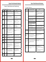
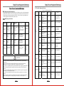
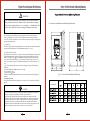
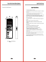
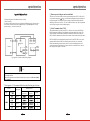
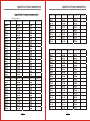
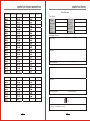
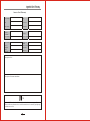
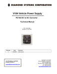
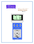
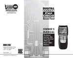
Chapter 3 Instructions for use of the product and specification for parameters
Chapter 3 Instructions for use of the product and specification for parameters
Definition for Parameter Address that can be used by COM
Definition
Setting parameters
inside the inverter
Parameter Address
Multi-stage speed value
Function Description
Remain
Remain
Counter value
E.g. The address of parameter P0-3: 13(0DH)
The address of parameter Pn-m: n*16+m (nmH)
Note: It is allowed to be read and overwritten,
but only one parameter can be read or overwritten.
Input AC voltage value
Invalid
Module temperature
Shutdown
Motor rotating speed
Remain
Start-up
Remain
Remain
Remain
Invalid
Positive direction command
Order to inverter
Remain
Remain
Negative direction command
Command given to change direction
Remain
Frequency order
Remain
Remain
Error code
No error
Remain
Remain
Error Response
The inverter will not respond if the data received is incomplete or the data failed to pass the
proof. Error response will bring out if the function code or address is incorrect though the
data received has passed proof. E.g.
Respond to inquiry command of the host
ASCII Mode
RTU Mode
Module
Monitor the
inverter state
Over-voltage
Overheat
Overload
Low voltage
Parameter register fault
OP trip
Communication
Default phase
Remain
Remain
Current setting frequency
Put the function codes received from the upper machine to a high bit 1, then error codes will be
followed. See detail instructions on error codes below:
Error Code
Description
Invalid command
Current operating frequency
Invalid address
Output current
DC voltage value
Invalid data
The inverter can not perform the requested operation of the user.
Output voltage
Chapter 4 Trouble Indication and Troubleshooting
Chapter 4 Trouble Indication and Troubleshooting
4.1 Trouble Display and Causes
Code
Content
Causes for anomalies
Chapter 4 Trouble Indication and Troubleshooting
4.2 Common Troubleshoot
Anomalies
Solution
Under-voltage 1)The input power and voltage are too low;
1)Check power and voltage.
2)There's a momentary outage of power;
during
3)There's a loose contact of relay DC loop. 2)Check the main circuit orseek service.
operation
1)The accelerating period is too short.
2)The load inertia is too large.
Over-current The inverter has a small power supply.
Overload
1)Over torque lifting
2) Excessively short acceleration time
3) Overload
4) Power grid voltage below level.
Overheat
1)The ambient temperature is too high.
2)The fan is damaged.
3)There's air binding to the exhaust.
Short
Circuit
1)Short circuit occurs at the output port.
2)There is short circuit among phases of the
inverter or error grounding.
3)There is a momentary over-currentof the
inverter.
4)The control panel is abnormal.
OP Trip
External Faults
Register Failure
The starting signal is closed before
it is energized.
The input terminals are closed because
of external equipment error.
There is failure inside the inverter.
1)Extend accelerating or decelerating
time .
2)Reduce load inertia.
3)Use an inverter with largerpower supply.
1) Reduce torque lifting value .
2) Extend acceleration time.
3) Replace an inverter with higher
power level.
4) Check power grid voltage.
1)Disconnect the starting signal.
2)Cancel OP protection function.
Disconnect the input terminal impacted by
external equipment failure and clear failure.
Seek Service.
1)The baud rate is improperly set.
2)Communication error occurs at the
serial port due to interference.
3)There is no communication signal in
the upper machine.
1)Adjust the baud rate.
2)Check the communication cable and
take more measures to prevent
interference.
3)Check if the upper machine runs
normally; the communication cable is
disconnected.
Over-voltage
1)The input voltage is abnormal;
2)The decelerating period is to o short.
3)There is energy feedbackload.
4)The voltage detection is abnormal.
1)Check the power supply.
2)Extent the decelerating period.
3)Choose proper braking units.
4)Seek service.
Current
Detection Error
1)Hoare is damaged or circuit is error.
2)DC auxiliary current error occurs.
Seek service.
Communication
Error
Check if the output terminal U, V or
W has output of voltage.
Check if there is overload which leads
Motor
doesn't rotate. to jamming of the motor.
Check if the inverter is normal or not.
Solutions
Disconnect the power supply and
restart again.
Confirm the grade of power voltage.
The terminal screw is tightly
fastened.
Disconnect the power supply and restart again.
Reduce loads to enable the motor to run.
Refer to troubleshooting.
Check if RWD/REV command has
been carried out.
1)Lower the ambient temperature.
2)Change the fan.
3)Clear up the exhaust and
improve ventilation.
1)Check the output wire or the motor.
2)Seek Service.
Key points to be checked
Check if there is input of power and
the control panel indicator is
ON.
Check if the frequency setting
signal has been sent out.
Make the frequency input wiring proper.
Set the frequency input voltage properly.
Check if the operation mode is set properly.
Select the mode by operation panel.
Check if the output U, V and W are
Motor counter correctly wired; FRD/REV signal is
rotates.
right or not.
Change two ends.
Check the wiring and correct it.
Motor couldn't Check if the frequency setting signal
for input is correct or not; the
change
operation mode is properly set or not;
speed.
the load is too heavy or not.
Check the wiring and correct it.
Run the motor by operation panel.
Reduce loads.
Check if the motor specifications (i.e.
Motor runs too polarity, voltage) is proper; the gear
ratio is proper or not; the value for the
fast or too
maximum output frequency is
slow.
proper.
The speed is
abnormal when
the motor
rotates.
Check if the load is too heavy; the
load fluctuation is too large; the input
power is stable.
Check the specifications of the motor.
Confirm the gear ratio.
Confirm the value for the maximum
output frequency.
Reduce loads.
Reduce load fluctuation.
Increase the inverter and the motor
capacity.
Install an AC reactor at inlet side
of input power supply.
Chapter 5InverterInspection
5 Inverter Inspectionand
andMaintena
Maintenance
nce
Chapter 5InverterInspection
5 Inverter Inspectionand
andMaintena
Maintenance
nce
5.1.2 Periodic Inspection Items
Chapter 5Inverter
5 Inverter Inspection and Maintenance
Table 5-2 Periodic Inspection Items
Inspection and Maintenance
The following influences may lead to latent failure of the inverter such as ambient temperature,
humidity, dust, vibration, as well as device ageing, wear and other causes of the inverter itself
during long-period operation on industrial occasions. So it is necessary to perform daily and
periodic inspections and maintenance on the inverter.
Target of Inspection
Inspection Items
Overall
Daily Inspection Items
Target of
Inspection
Check for...
Operating
ambient
Ambient
temperature;
Humidity, dust,
corrosive gas,
oil mist and etc.
Inverter
Vibration
Heat
Noise
Motor
Vibration
Heat
Noise
Electric
Parameter
Input voltage
Output voltage
Output current
Inspection Inspection
Cycle
Method
Criteria
Thermometer; between -10 to 40 , nocondensing;
Scent;
Humidity between 20 to
Visual.
90% no dew or special
Thermometer
Hygrometer
Main
circuit
odor.
Daily
Daily
Daily
Touch the
housing;
Aural.
Touch the
housing;
Aural.
Thermometer
Filter
capacitance
Contactor
Stable vibration
Normal temperature
No abnormal noise
Stable vibration
Normal temperature
No abnormal noise
Each electric
parameter is within
the rated value.
Resistor
Fan
Moving-iron
voltmeter;
Rectifier
voltmeter;
Clip-on
ammeter
WARNING
Make sure that only qualified personnel will perform maintenance, inspection and part
replacement.
Wait at least 10 minutes after turning OFF the input power supply before performing
maintenance or an inspection. Otherwise, there is the danger of electric shock.
Make sure to open the front panel only after the indicator on the control keypad turns OFF and
verify the charge indicator at the right side of main loop terminal is OFF after the panel is
opened.
Do use an insulated appliance while performing check and do not operate the equipment with
wet hand(s) to avoid unexpected accidents.
Always keep the equipment clean so that dust and other foreign matter does not enter the
inverter.
Keep electronic equipment away from moisture and oil. Dust, steel filings and other foreign
matter can damage the inverter, causing unexpected accidents, so do take special care.
Check if there is any
loose connector or
terminal.
Check if there is any
device burnt.
Main power
Check if it is
module
damaged or not.
Measuring
Instrument
Ambient temperature
Daily
Check for...
FPC strand
socket
Control
circuit
Overall
Keyboard
Inspection
Cycle
Visual
Regular
Regular
Check if there is any
leakage.
Check if there is any
inflation.
Regular
Check if there is any
abnormal sound of
actuation.
Check if dust has been
cleaned.
Regular
Check if there is
any big crack.
Check if the
color is abnormal.
Inspection
Method
Visual
Visual
Aural
Visual
Criteria
No loose connector
or loose terminal.
No burnt device.
No sign of damage.
No leakage;
No inflation.
Normal sound;
Clean.
Visual
No crack.
Normal color.
Regular
Aural
Visual
Normal sound
and stable
vibration.
Check if dust has
been cleaned.
Regular
Visual
Check if there is any
abnormal noise or
vibration.
Regular
Neat and clean.
Check if it is loose.
Regular
Visual
Check there is any
special odor or
discoloring.
Check if there is any
crack
Regular
Scent or audio
Check if the LED
display is normal.
Regular
Visual
Normal and clear.
Visual
No scratched surface.
No loose connection.
Check if there is any
scratch.
Connecting Check if it is
cable strand connected tightly.
Regular
No loose connection.
No odor and discoloring;
No crack, smooth surface.
Chapter 5InverterInspection
5 Inverter Inspectionand
andMaintena
Maintenance
nce
WARNING
Do not remove or shake the device arbitrarily, nor pull out the connector
during inspection. Otherwise, this may result in inverter failure or damage.
Do not leave any inspection tool (i.e., a screwdriver...) in the machine after
periodic check. Otherwise, there is the danger of damage to the inverter.
Chapter 6 Outline Dimension & Mounting Dimension
Chapter 6 Outline Dimension & Mounting Dimension
6.1 Inverter Outline Dimensions & Mounting Dimensions
5.2 Replacement of Wearing Parts
The wearing parts of inverter mainly include cooling fan and filter electrolytic capacitor.
Usually, a cooling fan's service life is 20,000~30,000 hours and an electrolytic capacitor's
service life is 40,000~50,000 hours. User can decide when to replace these parts according to the
corresponding operation time.
1 Cooling Fan
It is advisory to replace the fan when abnormal noise or even vibration occurred to the fan due to
bearing wear and fan blade aging. The standard replacement age is 2~3 years.
2 Filter Electrolytic Capacitor
The performance of filter electrolytic capacitor is subject to the pulsating current of main circuit.
High ambient temperature or frequent load jump may cause damage to the filter electrolytic
capacitor. Generally, every 10 rise in temperature may lead to reduction of the capacitor's
service life by half (as shown in Fig. 8-1). If there is any electrolytic leakage or safety valve
emission, just replace it at once. The standard replacement age for electrolytic capacitor is 4~5
years.
3 The above replacement duration for inverter's wearing parts is applied to the following
conditions:
Ambient Temperature: 30 averagely all year round;
Load Proportion: <85%;
Operation Time: 12h/day.
If used beyond the above mentioned range, the service life of the inverter's wearing parts will
minimize.
5.3 Storage of Inverter
Please pay attention to the following points if an inverter is set aside or stored for a short/long
period:
Fig.6-1 Inverter Outline Dimensional Drawings
Power
Inverter Models
CAUTION
DO not keep the inverter in a place with high temperature, humidity, heavy dust, metal
shavings, corrosive gas and vibration, and ensure a good ventilation.
Long-term idle of the inverter may cause decreasing in filter characteristic of the
electrolytic capacitor. So it should be recharged within 2 years and the recharging period
should be at least 5 hours. DO raise the voltage gradually by using a voltage regulator to
some rated value before it is recharged. At the same time, check whether the inverter's
function is normal or not, whether there is a short circuit caused by some problems. In case
the above problems occur, just remove or seek service as soon as possible.
Dimension
Chapter 6 Outline Dimension & Mounting Dimension
6.2 Operation Panel Outline Dimension
Appendix 1 Quality Warranty
Appendix 1 Quality Warranty
1. Warranty Period under Normal Conditions
We provide guarantees for repair, replacement and return of the purchase in 1 month from
the date of use.
We provide guarantees for repair and replacement in 3 months from the date of use.
We provide guarantee for repair in 12 months from the date of use.
2. If the date of use can not be verified, then the warranty period shall be 18 months from the
date of manufacture. Service exceeding the warranty period shall be charged to the
purchaser. The purchaser enjoys life-long paid service whenever and wherever he uses an
inverter made in our company.
3. Service in the following cases, even within the warranty period, shall be charged to the
purchaser:
Damage caused by mal-operation in violation of this manual;
Damage caused by improper use of an inverter that is off technical standard and
requirement;
Malfunction or damage caused by fire, earthquake, flood, abnormal input voltage or other
natural disasters;
Artificial damage caused by unauthorized repair or renovation;
Induced failure or aging of the device due to poor ambient;
Delayed or unsatisfied payment in violation of purchase appointment;
Unidentifiable nameplate, mark and date of manufacture
Malfunction or damage caused by improper transit or storage after purchase;
Fail to give an objective description on the use of installation, wiring, operation,
maintenance or else;
Defective products should be sent to us for repair, replacement and return, which can be
proceeded only after verifying the burden of liability.
4. In case there is any quality problem or accident, we merely promise to bear the abovementioned responsibilities. If a user needs more guarantees for liabilities, please assure on
the insurance company voluntarily.
Fig.6-2
Panel Dimension
Appendix 2 Optional Parts
Appendix 2 Optional Parts
Appendix 2 Optional Parts
2
All the optional parts can be ordered for with us if needed.
1. Brake Assembly
The brake assembly consists of two parts: braking unit and braking resistor. It is necessary to
install a brake assembly on the occasion that quick stop is required though there is a heavy
potential load (e.g., elevator) or inertia load.
Remote-operated adapter and extended cable
There are two selections available for remote operation on the inverter ZVF11-M/S series. If
it is operated at short range
15m , just extend the shielding cable directly and connect it
to the operator panel. The company can provide a range of extended shielding cables with
different specifications such as 1m, 1.5m, 2m, 5m and 10m. If there is any special requirement
on cable length, just place an order with the company.
3
Serial Communication (COM)
The standard machine type of the inverter ZVF11-M/S series does not provide RS232 and
RS485 communication function. User shall mark out the function at the time of order. The
control terminals of standard RS232 and RS485 communication interface may connect to
RS232 or RS485 communication cable to realize network control or ratio interlocking control.
braking resistor
Braking unit
Inverter
Fig. Appendix 1-1 Brake Assembly Wiring Diagram
TIPS
When installing a brake assembly, DO take into consideration of the safety of the
surrounding ambient.
For detailed parameters and introduction to the function, please refer to Brake Assembly
User's Manual.
Table Appendix 1-1 Recommended Brake Assembly Matching Specifications
Inverter
Voltage
Braking unit
Braking resistor
Recommended
resistance value
Motor
Built-in
Built-in
Built-in
Built-in
Resistor
specification
Quantity
RS232 and RS485 serial communication protocol for the inverter ZVF11-M/S series can be
operated under Windows98/2000. The monitoring software for this series, featured by
friendly man-machine operation interface, can easily realize networking operation and
perform monitoring and other functions of the inverter. Please contact the service center of
our company or our agents if it is needed.
Appendix 3 User's Parameter Amendment Record
Appendix 3 User's Parameter Amendment Record
Appendix 3 User's Parameter Amendment Record
Function Code Setting Value Function Code Setting Value Function Code Setting Value
Table Appendix 3-1
Function Code Setting Value Function Code Setting Value Function Code Setting Value
Function Code Setting Value Function Code Setting Value Function Code Setting Value
Function Code Setting Value Function Code Setting Value Function Code Setting Value
Appendix 3 User's Parameter Amendment Record
Appendix 4 User's Warranty
User's Warranty
Function Code Setting Value Function Code Setting Value Function Code Setting Value
User's Details
Name of
Distributor
Inverter Model(s)
Date of Purchase
Identification
Number
Name of
Equipment
Power Capability
of the Motor
Date of
Installation
Date of Use
Maintenance Record
Failure Cause
Settlement
Date of Maintenance
Serviceman Signature
Failure Cause
Function Code Setting Value Function Code Setting Value Function Code Setting Value
Settlement
Date of Maintenance
Serviceman Signature
TIP
This copy is for the holder (user) only.
Appendix 4 User's Warranty
Inverter User's Warranty
User's company
Add
Contact Person
Name of
Distributor
Date of Purchase
Inverter Model(s)
Tel
Post Code
Department
Add/Tel
Invoice Number
Identification
Number
Name of
Equipment
Power Capability
of the Motor
Date of
Installation
Date of Use
Description of Use
Description of Parameter Amendment
TIP
User shall fill it out based on the facts with care and return it to us as soon as possible, so
that we could serve you better service to avoid inconvenience or loss caused by your improper
installation or error use.