1
INVERTER ZVF11-M/S Series
User's Manual
Foreword
Thank you for your purchase of the ZVF11-M/S Series inverter
This manual introduces the installation, operation, function
setting, troubleshooting and etc. of the inverter ZVF11-M/S series.
Incorrect installation or use may result in damage or other
accidents. Do read all instructions in detail before installing or
operating.
Please forward this manual to the end user, and keep it handy for
quick reference.
If there are any doubts or questions, please contact the Technical
Service Center of the Company.
Table of Contents
Table of Contents
Chapter 1 Safety Instruction .................................1
1.1 Safety Symbols and Definitions ..........................1
1.2 Cautions for Use ............................................... 2
1.3 Cautions for Operating Ambient..........................3
Chapter 2 Introduction to the Product
and Installation ..................................................4
2.1 Product Inspection upon Arrival .........................4
2.2 Demonstration of the Model ...............................4
2.3 Demonstration of the Nameplate ........................4
2.4 Specification and Technical Indications ..............5
2.5 Installing and Wiring ........................................ 6
Chapter 3 Instructions for use of the
product and specification for parameters ........... 13
3.1 Operation Panel Specification ......................... 13
3.2 Function Parameters List ................................ 16
3.3 Function Parameters Specification ...................30
Chapter 4 Trouble Indication and
Troubleshooting ................................................. 57
4.1 Trouble Indication and Malfunction Causes ...... 57
4.2 Common Troubleshoot .................................... 58
Chapter 5 Inspection and Maintenance ............... 59
5.1 Inspection and Maintenance .............................59
5.2 Replacement of Wearing Parts ..........................61
5.3 Storage of Inverter ...........................................61
Table of Contents
Table of Contents
Chapter 6 Outline Dimension &
Mounting Dimension ........................................62
6.1 Inverter Outline Dimension &
Mounting Dimension ..........................................62
6.2 Operation Panel Outline Dimension ................63
Appendices .......................................................64
Appendix 1 Quality Warranty ..............................64
Appendix 2 Optional Parts ...................................65
Appendix 3 User's Parameter
Amendment Record .............................................67
Appendix 4 Warranty ...........................................70
Chapter 1 Safety Instructions
Chapter 1 Safety Instructions
Chapter 1 Safety Instructions
1.1 Safety Symbols and Definitions
The safety instructions described in this manual are very important.To avoid
any errorthat may result in damage to equipment, injury to personnel or loss of
property, do read and clearly understand all of the safety symbols, symbol
definitions and be sure to observe the indicated safety instructions below.
Safety Symbols
HAZARD
WARNING
Symbol Definitions
WARNING
Be sure the power supply and voltage selected should be equivalent to the
input voltage of the inverter.
This symbol indicates hazardous HIGH VOLTAGE. Any
incorrect operation may result in serious damage to the
equipment or death to personnel.
This symbol indicates that any incorrect operation can result
in damage to the equipment or minor to moderate injury to
personnel.
This symbol calls your attention to follow the instructions
while in operation or in use.
CAUTION
TIP
Cautions for Use
Before power transmission
This symbol calls your attention to some useful messages
for the user.
WARNING
Be sure to install the inverter on metallic or other inflammable materials to
avoid fire.
Be sure to install a fan if several inverters are put in one cabinet, so that the
temperature inside the cabinet is always below 40 , thus overheat or fire
can be prevented.
Be sure not to dismount or install the operation panel and avoid failure or no
display of the panel due to loose contact.
During power transmission
HAZARD
HAZARD
Do not touch the circuit board or the parts when the power or the charge indicator is still on.
Do not perform the work of wiring or inspecting the parts or signal of the circuit board
unless the power supply is completely off.
Do not dismount or change the connecting wires, circuits or parts inside the inverter by
yourself.
Do connect the inverter's earth terminal to the ground properly and tightly.
DO NOT insert or pull the connecting lines of the inverter to avoid damage
of the control panel caused by surge that enters the panel.
During operation
HAZARD
WARNING
Do not perform withstand voltage test on the internal parts of the inverter because
semiconduction parts can be easily damaged by the voltage.
Do not connect the output terminal U, V or W of the inverter to the terminal L or N of AC
power supply.
Do not touch the main circuit board of the inverter because its CMOS and IC are
vulnerable to static damage.
DO NOT insert or isolate the motor during operation. Otherwise, it may
cause overcurrent protection or even result in burnout of the main circuit of the
inverter.
KEEP CLEAR to avoid danger if self-priming (automatic start) is set which
can restart automatically after the motor stops.
DO NOT remove the terminal cover to prevent possible electric shock and
injuries.
Chapter 2 Introduction to the Product and Installation
Chapter 2 Introduction to the Product and Installation
2.1 Unpacking and Inspection upon Arrival
This product is guaranteed a high level of quality with strict outgoing inspection,
crushproof and shockproof packaging. But this does not preclude damage to the
product due to heavy collision or strong extrusion. So it is necessary to unpack
the inverter upon arrival and perform these steps:
Check whether there is a deformed or damaged casing; or any shattered
component.
Check the nameplate of the inverter and make sure it matches the product part
number you've ordered.
If there is any problem with the above-mentioned contents, please contact with the
supplier or manufacturer immediately.
2.2 Demonstration of the Model
Inverter Model
Design Serial
Number
Serial Number
Mini Type
Economic Type
Code
Economic Type
Code
Voltage Class
M
S
380V
Voltage Phase
Single Phase
Three-phase
Figure 2-1 Inverter Model Demonstration
2.3 Demonstration of the Nameplate
Trademark
Inverter Model
Motor Power
Input Power Rating
Output Power Rating
PIN
Figure 2-2 Specifications Label
Code
4
Code
T
Chapter 2 Introduction to the Product and Installation
Specifications and Technical Indications
Input Voltage Class
ZVF11-M/S_ _ _
Applicable Motor Power (KW)
Output Current(A)
Output Maximum Output Voltage(V)
Corresponding Three-phase Input Voltage
Range of Output Frequency(Hz)
Range of Input Voltage
Input Range of Input Power Frequency
SAPWM
Frequency Resolution
Figure Setting: 0.01Hz Analog Setting: Maximum Frequency*0.1%
Torque Characteristics
Adjustable from 0% to 20%.
Overload Capacity
150% of the rated output current per minute
Installation and Wiring
2.5.1 Operating Environment:
The Inverter mounting ambient have direct effect on the function and lifetime of
inverter, So the ambient have to reach the followingsituation:
Altitude: Maximum 1000m above sea level
Ambient Temperature: -10~+45 [Bare Machine: -10~+50 ]
Humidity: 20~90% RH (Non-condensing)
Ambient: Indoor places free from direct exposure to sunlight, dust, corrosive gas,
flammable gas, oil mist, steam, drip and salt.
Vibration: < 0.5G
2.5.2 Installation Space and Direction
To get better cooling effect and for the convenience of maintenance, the inverter
shall be installed vertically with enough space left (refer to Fig.2-3). When two or
more inverters are fixed in the same cabinet, it is recommended to fix them in
parallel and horizontally to reduce heat produced by them (refer to Fig.2-4). When
there is a must to fix them up and down, please fix an insulating board between them
so that the heat produced by the lower one could not have direct influence on the
upper one (refer to Fig.2-5).
Acceleration/Deceleration time Adjustable from 0.1 to 999.9.
V/F Curve
Panel Control Set by the key
External Signal
Panel Control
Operation
Setting Signal External Signal
Air outlet
Terminal 0~10V, 4~20mA 0~10KHz
UP/DOWN 485 COM etc.
Multi-function Output Signal
Failiure,running,counter arrival,frequency arrival
program running
Analog Output Signal
Running frequency,output voltage , current,motor
rotation
Overvoltage, overcurrent, undervoltage, overload, overheat,
short circuit protection and etc.
Cooling Mode
Forced air cooling
Ambient
External Environment
>
>
Fig.2-3 Diagram of
Installation Space
Air inlet
Induced
spacer
Air inlet
Fig.2-4 Diagram of Multi-piece
Parallel Installation
Fig.2-5 Diagram of
Multi-piece Vertical
Installation
AVR, overvoltage andcurrent stall prevention, no reversal andetc.
Protecting Functions
Points of Use
>
Set by the key RUN or STOP.
External FWD, REV and JOG operation, PLC operation and
COM operation.
Multi phase speed, counter, programrun, VI/CI shifting and etc.
Other Functions
Air outlet
or the potentiometer on the panel.
Multi-function Input Signal
Vibration
>10cm
Inverter
Running Characteristics
Frequency
Setting Signal
Air outlet
Linear/ Quadratic
Inverter
Control Characteristics
Control Mode
Chapter 2 Introduction to the Product and Installation
Altitude < 1000m, indoor places without corrosive gas, liquid and etc.)
Temperature: -10~+45 ; Humidity < 90%RH without condensing
< 0.5G
WARNING
Be sure the main loop terminals should be connected to the cable tightly. Otherwise, the
inverter may be damaged arising from loose connection.
Be sure the ground terminals of the inverter and the motor must be properly grounded.
Multi-piece inverter should be grounded at one shared point.
Be sure to install a non-fuse circuit breaker or leakage protective circuit breaker in the
inverter's input port toprevent expanding of accident due to inverter problem.
Chapter 2 Introduction to the Product and Installation
Inverter's Standard Wiring Diagram
Chapter 2 Introduction to the Product and Installation
Instructions for Main Circuit Terminals
Diagram of Main Circuit Terminals
Braking Resistance
Three-phase
AC Input
Power Supply
Terminal X1
Terminal X2
Terminal X3
Terminal X4
Terminal X5
Terminal X6
Public Terminal
Fault Relay Output
TA-TB on when normal.
TA-TC on when failure.
Connect with ground
Single phase 220V power input
Fig.2-7 Input Terminals
Open collector
Output
Analog Signal Output
(0-10VDC or 0-20mA
Potentiometer
Input or Analog
Voltage Input
24 Power Supply Output Port
Analog
Current Input
(0-20mA)
485 COM Port
Connect with the braking resistor
Connect with three-phase AC motor
Fig. 2-6 Basic System Description on Wiring
Fig.2-8 Output Terminals
Chapter 2 Introduction to the Product and Installation
Description on
Terminal Symbol
Circuit Terminals
Chapter 2 Introduction to the Product and Installation
Description of Control Circuit Terminals
Function Description
Power input terminals connecting to single-phase 220V AC power supply
Diagram of Control Circuit Terminals
Inverter output terminals connecting to three-phase AC motor
External braking resistance terminals connecting to both ends of the external braking resistor.
Ground terminal or ground wire.
Tips
Fig.2-9 Control Terminals
The input power terminals do not differ on phase sequence and can be connected arbitrarily.
If the motor counter rotates (reverses) when the output terminals U, V and W connect to
three-phase motor, just exchange two phases of U, V and W arbitrarily.
Description of Control Circuit Terminals
Types
Public Port
WARNING
The inverter's ground lead can not connect to the ground together with other heavy current
load, but connect to the ground separately. The shorter of the ground line is , the better is.
The ground terminal is required to have a tight ground contact to avoid electric shock or
fire and reduce noise. Do not form a loop if several inverters connect to the ground together.
Refer to the figure below.
Multi-function
Input Terminal
Power Supply
Correct
Correct
Incorrect
Multi-function
Output
Terminal
Public Port
WARNING
The diameter of the ground line must conform to the state standards.
. Make sure the excellent connection, Please use the terminal with insulating pipe to connect
the terminal with lead.
After wiring is finished, check carefully if there is any foreign matter come into the inverter.
Confirm all the connection lines are proper without any missing or wrong connection. Be
sure there is no short circuit between terminals and connection lines, or short circuit to earth.
Analog Input
Terminal
Terminal Symbols
Function Description
Valid only when there is a
short-circuit between Xn
(n=1, 2, 3, 4, 5, 6) and COM.
Th functions can be set by
parameter F3.00~F3.05
separately.
24VDC Power
Output(Control Power)
Multi-function open-collector
output is defined as on-off
output terminal, whose
function is set by the parameter
F3.09 with reference of COM
INPUT, 0~24 power level,
low level valid, 5mA
24VCD/100mA
OUTPUT Maximm
load current 50mA
Analog Signal Public Terminal
External analog preset power supply
DC Voltage
Analog voltage signal input,
with referenceof GND.
DC Voltage
Analog current signal input,
with reference of GND
Analog Output
Terminal
Electrical Specifications
Numeral Signal Public Terminal
Analog voltage currentoutput
with reference of GND.
DC Current
Chapter 2 Introduction to the Product and Installation
Types
Multi-function
Relay Output
Terminal
Terminal Symbols Function Description
Electrical Specifications
Set by the parameter F3.08.
Normal: TA-TB closed
Failure: TA-TC closed
Contact capacity:
Communication Signal Positive Terminal
COM Terminal
Chapter 2 Introduction to the Product and Installation
Diagram of Wiring for Inverter System & Cautions for Wiring
Power Supply
Power Supply
Be sure the voltage class is proper to avoid damage tothe
inverter.
A non-fuse breaker must be installed between the AC
power supply and the inverter.
non-fuse breaker
non-fuse breaker
Be sure to use a non-fuse breaker which matches the rated
voltage and current of the inverter. It is used as an On/Off
switch between the inverter and the power supply, and a
protector for the inverter.
Do not use the non-fuse breaker to start or stop the inverter.
Communication Signal Negative Terminal
Electromagnetic
Contactor
Tips
The connecting wire of control circuit must be STP (shielded twisted pair wire) which
should be separated from the main circuit and strong current circuit. If the connecting wire of
the control circuit had to pass through the main circuit and other control wires, they must
intersect at an angle of 90o.
The control circuit is liable to external interferences. So the length of the wire should be
short as possible. Usually, it can not exceed 30m. When used for analog voltage, current or
potentiometer input, the wire should not exceed 20m in length.
To avoid loose contact, a tight contact is recommended when taking a joint as input.
To remove malfunction of surge voltage on the inverter's control circuit and peripheral
equipment, a surge absorber should be installed to connect two ends of the magnetic coil that
has generated surge voltage.
The diameter of the control circuit wire is recommended to be 0.75mm2.
AC reactor
Electromagnetic Contactor
A contactor is not used generally. But it must be installed
when certain functions, i.e., external control, restart are
performed.
Do not use the electromagnetic contactor to start or stop the
inverter.
AC reactor
Input Filter
Input Filter
An input filter should be mounted if there is inductive load
around the inverter.
Inverter
Schedule of Matching Electrical Products
Model
Maximum
Applicable Motor
Main Circuit Diameter
Circuit Breaker
Contactor
Output Filter
Three-phase Motor
Inverter
The power can be connected to the terminal L or N
arbitrarily.
The output port can be connected to the terminal U, V and
W. If the motor reverses when the inverter forwards, just
exchange two phases of U, V and W arbitrarily.
Do not connect output terminal to AC power supply.
Otherwise, it may cause damage to the inverter.
The ground terminal should be properly grounded.
Chapter 3 Instructions for use of the product and specification for parameters
Chapter 3 Instructions for use of the product and
specification for parameters
Chapter 3 Instructions for use of the product and specification for parameters
3.1.1 Description on Keys
Symbol
3.1 Specification for Operation Panel
Key Name
Mode key.
3.1.1 Operation Panel Outlay
key.
Up key.
Down key.
display area, display
frequency, current,
parameters, error and etc.
Run key.
LED display area, display
the running status.
MODE Key
RUN Key
SHIFT Key
STOP/RESET/SHIFT Key
Stop/Reset key.
Function Description
Press this key to enter intothe function programming mode. Once
parameters are modified, press this keyto exit the function programming
mode.
In the state of programming, pressthis key to confirm the functioncode.
After parameters are modified, press thiskey to save modified data. Inan
operation or hold mode, press thiskey to shift the displaying content,such
as output frequency,current ,revolution.
In the state of programming, thefunction code and parameter value will
go up by pressing this key. In an operation or holdmode, press this key to
increase the operation frequency.
In the state of programming,Pressing this key, the function codes and
parameter value will go down. Inan operation or hold mode, pressthis
key to decrease the operation frequency.
Pressing this key, the inverter begins to run. If "F0.02"is set to "External
Terminal Control", then it is invalid to press this key.
Press this key to stop theinverter. If "F0.02" is setto "External Terminal
Control", then it is invalid topress this key. Whenfailure alarm occurs,
press this key to reset thesystem. In the state of programming,press this
key to realize data traverse.
3.1.2 Description on LED Indicator Lights
Description
LED Symbol
UP/DW Key
Panel Potentiometer
Run Indicator
Stop Indicator
Forward Indicator
Reverse Indicator
Fig.3-1 Diagram for Z
Operation Panel
This Light turns ON when the inverter runs.
This Light turns ON when the inverter stops.
This Light turns ON when the inverter forwards.
This Light turns ON when the inverter reverses.
Tips
The LED displays -VF- when the inverter is energized.
In the operation or hold mode, pressing
, the frequency value can be modified when
it is set by Up/Down key
on the panel (F0.01=1).
In the operation or hold mode, pressing
, the display can shift to the output
frequency, current, rotating speed and etc
In the state of operation, the stop function of
key is prior to the reset
function, i.e., to modify a parameter when the inverter is in operation, pressing this key, the
inverter will stop running. (Note: The operation mode is set to "Panel Control".)
Chapter 3 Instructions for use of the product and specification for parameters
Chapter 3 Instructions for use of the product and specification for parameters
3.1.2 Use of the Operation Panel
3.2 List of Function Parameters
1 Change the frequency set mode from
control to external voltage (0~10V) control.
F0 series Basic Parameters
Initializing
Function
Code
Change
Name
Range of setting
Minimum
Unit
Factory
Default
Setting
Keyboard setting
frequency
2 Change the acceletion time from 10.0s to 20.0s.
Frequency
setting
mode
Initializing
3 Restore all the parameters to Factory Default Settings
Initializing
Delay several seconds
Operation
command
selection
0: Keyboard control
1: Terminal control
2: Multi-stage speed control
3: External analog voltage input
control
4: External analog current input
control
5: 485 COM control
Stop mode
0: Free stop
1: Decelerated stop
Basic frequency
upper limiting
frequency
lower limiting
frequency
Notes
Acceleration time
Deceleration time
indicates the data tube flickers;
indicates the tube doesn't flicker.
To modify parameters when the inverter is in operation, the inverter will stop running
when pressing the
key. (Note: The operation mode is set to "Panel Control".)
To modify parameters when the inverter is in operation, please pay attention to the
modification right because some parameters can not be modified in the operation mode.
If parameters cannot be modified in the hold mode, please check whether the parameters
are locked or not (Fc.12=1).
0: Keyboard or terminal setting by
pressing UP/DOWN
1: Keyboard potentiometer setting
2: External analog voltage setting
3: External analog current setting
4: Combined multi-stage speed
setting
5: External terminal high/low
speed setting (AVI)
6: External impulse input setting
7: PID setting
8: 485 COM setting
9: Terminal AVI/ACI setting
Starting frequency
Starting
Shutdown frequenc
Frequency fine tuning
1
Note
Chapter 3 Instructions for use of the product and specification for parameters
F0 series Basic Parameters (Continued)
Function
Code
Range of setting
Name
Chapter 3 Instructions for use of the product and specification for parameters
F1 series Control Parameters (Continued)
Minimum
Unit
Factory
Default
Setting
Note
Function
Code
Name
Jog frequency
Torque lifting
Jog acceleration time
Output voltage
regulating
Range of setting
Factory
Default
Setting
Note
Minimum
Unit
Factory
Default
Setting
Note
Minimum
Unit
Factory
Default
Setting
Note
Minimum
Unit
Jog Deceleration time
F2 series Braking and Braking Displaying Parameters
F1 series Control Parameters (Continued)
Function
Code
Range of setting
Name
FWD/REV
command
selection
Keyboard operating
direction
Function
Code
Minimum
Unit
Factory
Default
Setting
Note
Forward
Starting DC
braking voltage
Shutdown DC
braking time
1 Reverse
Shutdown DC
braking voltage
FWD/REV shifting
time
Braking enable
0: Linear type (constant torque load)
V/F curve setting 1: Square type (fan, pump)
Braking inception
voltage coefficient
IF setting
Braking termination
retard coefficient
2
IF output voltage
setting
Polygonal type (F1.04, F1.05)
(Valid when F1.03=2
0-7 (Valid when acceleration
time<10s)
Deceleration S
curve setting
0-7 (Valid when deceleration
time<10s)
Leap frequency range
1st leap frequency
2nd leap frequency
3rd leap frequency
Carrier frequency
Display mode 1
(Valid when F1.03=2
Acceleration S
curve setting
Range of setting
Starting DC
braking time
0: No reversing
1: Keyboard selection
2: External terminal selection
3: 485 COM selection
0
Name
Display mode 2
Display mode 3
0
Invalid
1: Valid
0 Frequency display 5: Count input value
1: Output current
6 AVI feedback value
2 Input voltage
7 ACI feedback value
3 Output voltage
8 PID setting value
4: Motor rotating speed 9: PID feedback value
F3 Series Multi-function port parameters
Function
Code
Name
Terminal X1
function selection
Terminal X2
function selection
Range of setting
0 Invalid
1: Combined multi-stage speed 1
2: Combined multi-stage speed 2
Chapter 3 Instructions for use of the product and specification for parameters
F3 Series Multi-function port parameters (Continued)
Function
Code
Name
Terminal X3
function selection
Terminal X4
function selection
Terminal X5
function selection
Terminal X6
function selection
Output target
frequency setting
Frequency
detection range
Range of setting
3: Combined multi-stage speed 3
4 Combined
accelerating/decelerating time 1
5 Combined
accelerating/decelerating time 2
6 Forward operation (FWD)
7: Reverse operation (REV)
8: RUN
9 Running direction selection
(forward or reverse)
10 JOG forward
11: JOG reverse
12: Reset (RST)
13: Counter reset
14: Counter Up input
15: Counter Down input
16 External impulse input
17 Pulse enable
18 Frequency increasing (UP)
19: Frequency decreasing
(DOWN)
20: External fault
21 PLC pulse start
22 PLC pulse stop
23: Three-wire FWD control
24: Three-wire REV control
25 Three-wire NO shutdown
control
26 Three-wire NC shutdown
control
27 External free shutdown input
28 External decelerated
shutdown input
29: Analog frequency command
selection (AVI/ACI)
30: Terminal high/low speed
selection
Minimum
Unit
Chapter 3 Instructions for use of the product and specification for parameters
F3 Series Multi-function port parameters (Continued)
Factory
Default
Setting
Note
Function
Code
Name
Relay function
selection
Y1 function
selection
Range of setting
Minimum
Unit
Factory
Default
Setting
Note
Minimum
Unit
Factory
Default
Setting
Note
0 Invalid
1 Fault output
2: Target frequency arrived
3: Set frequency arrived
4: Operation output
5: Counter arrived
6: upper limiting frequency
arrived
7: lower limiting frequency
arrived
8 Program operating indication
F4 Series Multi-stage Speed Parameters
Function
Code
Name
Multi-stage speed 1
Multi-stage speed 2
Multi-stage speed 3
Multi-stage speed 4
Multi-stage speed 5
Multi-stage speed 6
Multi-stage speed 7
1st accelerating
time
1st decelerating
time
2nd accelerating
time
2nd decelerating
time
3rd accelerating
time
Range of setting
Chapter 3 Instructions for use of the product and specification for parameters
Chapter 3 Instructions for use of the product and specification for parameters
F4 Series Multi-stage Speed Parameters
F6 series Communication and Fault Parameters
Function
Code
Name
Range of setting
Minimum
Unit
Factory
Default
Setting
Note
Function
Code
Name
3rd decelerating
time
4th accelerating
time
4th decelerating
time
Acceleration/Deceleration
source selection
Range of setting
0: 8-N-1, 8-bit data,
1 bit stop, no parity RTU
1: 8-E-1, 8-bit data,
1 bit stop, even parity RTU
2: 8-0-1, 8-bit data,
1 bit stop, odd parity RTU
0: Keyboard setting
1: Terminal selection
3: 8-N-2, 8-bit data,
2-bit stop, no parity, RTU
F5 Series Protection Function Parameters
4: 8-E-2, 8-bit data,
2-bit stop, even parity, RTU
Undervoltage
protection
Undervoltage
Protection Voltage
Proportion
Over-voltage
protection Function
Over-voltage
protection voltage
proportion
Over-voltage stall
function
Over-voltage stall
voltage proportion
Over-current stall
function
Stall current
proportion
5: 8-0-1, 8-bit data,
2-bits stop, odd parity, RTU
0: Disabled 1: Enabled
6: 7-N-1, 8-bit data,
1-bit stop, no parity, ASCII
50%-100%
7: 7-E-1, 8-bit data,
1-bit stop, even parity, ASCII
0: Disabled 1: Enabled
100%-150%
485 COM Mode
8: 7-0-1, 8-bit data,
1-bit stop, odd parity, ASCII
9: 7-N-2, 8-bit data,
2-bit stop, no parity, ASCII
0: Disabled 1: Enabled
10: 7-E-2, 8-bit data,
2-bit stop, even parity, ASCII
100%-150%
11: 7-0-2, 8-bit data,
2-bit stop, odd parity, ASCII
0: Disabled 1: Enabled
12: 8-N-1, 8-bit data,
1-bit stop, no parity, ASCII
100%-150%
Overload protection
0: Disabled 1: Enabled
Overload current
proportion
10%-200%
Overload
protection time
0-120s
13: 8-E-1, 8-bit data,
1-bit stop, even parity, ASCII
14: 8-0-1, 8-bit data,
1-bit stop, odd parity, ASCII
15: 8-N-2, 8-bit data,
2-bit stop, no parity, ASCII
Overheat function
0: Disabled 1: Enabled
16: 8-E-2, 8-bit data,
2-bit stop, even parity, ASCII
OP trip function
0: Disabled 1: Enabled
17: 8-0-2, 8-bit data,
2-bit stop, odd parity, ASCII
Minimum
Unit
Factory
Default
Setting
Note
Chapter 3 Instructions for use of the product and specification for parameters
F7 Series PID Function Parameters (Continued)
F6 series Communication and Fault Parameters (Continued)
Function
Code
Name
Range of setting
Minimum
Unit
Factory
Default
Setting
Note
Function
Code
Name
PID feedback
selection
485 COM baud
rate selection
Range of setting
0
1
ositive feedback
Proportional
gain Kp
485 COM
local address
Communication
error report
Chapter 3 Instructions for use of the product and specification for parameters
Integral time Ki
Differential time Kd
0: Disabled 1: Enabled
PID tolerance range
Error-recoverable
times
Error recovering
time
PID detection time
Last error type
For search
Next-to-last
error type
For search
Antepenultimate
error type
For search
Sleep time
Frequency wake-up
threshold
Encoder speed setting
Encoder impulse
times per week
Reserved function
F7 Series PID Function Parameters
F8 Series
PID setting
source selection
0: Keyboard set, AVI feedback
1: Keyboard set, ACI feedback
2: Keyboard potentiometer set,
AVI feedback
3: Keyboard potentiometer set,
ACI feedback
4: AVIset, ACI feedback
5: ACI set, AVI feedback
Analog Input/Output Parameters
Maximum voltage value for
analog voltage input
Minimal voltage value for
analog voltage input
Frequency that corresponds to the
maximum voltage for analog input
Frequency that corresponds to the
minimal voltage for analog input
PID digital set
PID upper limiting
frequency
PID lower limiting
frequency
Maximum current value for analog
current input
Minimal current value for analog
current input
Minimum
Unit
Factory
Default
Setting
Note
Chapter 3 Instructions for use of the product and specification for parameters
F8 Series
Function
Code
F9 series PLC Function Parameters 1 (Continued)
Analog Input/Output Parameters (Continued)
Range of setting
Name
Minimum
Unit
Chapter 3 Instructions for use of the product and specification for parameters
Factory
Default
Setting
Note
Function
Code
Name
Frequency that corresponds
to the maximum current for
analog input
PLC operating
frequency stage 5
Frequency that corresponds
to the minimal current for
analog input
PLC operating
frequency stage 6
Maximum value for
external impulse input
PLC operating
frequency stage 7
Minimal value for external
impulse input
PLC operating
frequency stage 8
Frequency that corresponds
to the maximum value for
impulse input
PLC operating
frequency stage 9
Frequency that corresponds
to the minimal value for
impulse input
PLC operating
frequency stage 10
Analog output enable
Analog output
content selection
Range of setting
Minimum
Unit
Factory
Default
Setting
Note
Minimum
Unit
Factory
Default
Setting
Note
PLC operating
frequency stage 11
0: Disabled 1: Enabled
0: Operating
3: Motor rotating
frequency
speed
1: Output voltage 4: PID set value
2: Output current 5: PID feedback value
PLC operating
frequency stage 12
PLC operating
frequency stage 13
Analog output
correction coefficient
PLC operating
frequency stage 14
Frequency that corresponds
to the maximum value for
analog output
PLC operating
frequency stage 15
PLC operating
frequency stage 16
F9 series PLC Function Parameters 1
FA series PLC Function Parameters 2
PLC operating frequency stage 1
Function
Code
Name
PLC operating frequency stage 2
PLC operating time
stage 1
PLC operating frequency stage 3
PLC operating time
stage 2
PLC operating frequency stage 4
PLC operating time
stage 3
Range of setting
Chapter 3 Instructions for use of the product and specification for parameters
FA series PLC Function Parameters 2 (Continued)
Function
Code
Name
Range of setting
Fb series PLC Function Parameters 3 (Continued)
Minimum
Unit
Factory
Default
Setting
Note
PLC operating control
stage 5
PLC operating time
stage 6
PLC operating control
stage 6
PLC operating time
stage 7
PLC operating control
stage 7
PLC operating time
stage 8
PLC operating control
stage 8
PLC operating time
stage 9
PLC operating control
stage 9
PLC operating time
stage 10
PLC operating control
stage 10
PLC operating time
stage 11
PLC operating control
stage 11
PLC operating time
stage 12
PLC operating control
stage 12
PLC operating time
stage 13
PLC operating control
stage 13
PLC operating time
stage 14
PLC operating control
stage 14
PLC operating time
stage 15
PLC operating control
stage 15
PLC operating time
stage 16
PLC operating control
stage 16
Fb series PLC Function Parameters 3
PLC operating control
stage 1
PLC operating control
stage 2
Name
PLC operating control
stage 4
PLC operating time
stage 5
Name
Function
Code
PLC operating control
stage 3
PLC operating time
stage 4
Function
Code
Chapter 3 Instructions for use of the product and specification for parameters
Range of setting
Minimum
Unit
Factory
Default
Setting
Note
Range of setting
Minimum
Unit
Factory
Default
Setting
Note
Chapter 3 Instructions for use of the product and specification for parameters
3.3 Function Parameters Description
Fc series Auxiliary Control Parameters
Function
Code
Name
PLC function
setting
Range of setting
0: Non operation
1: Single cycling
2 Continuous Cycling
3 Retaining the final value
after single cycling
AVI/ACI filter
time
Speed correction
Remain
ACI fine tuning
Digital frequency
control
0: Keep memory after power failure; hold
after shutdown.
1 Keep memory after power failure; don't
hold after shutdown.
2: Don't keep memory after powerfailure;
hold after shutdown.
3 Don't keep memory after power failure;
don't hold after shutdown.
Digital frequency range
Standby time
Motor poles
Counter target value
Counter arrival
motion time
Output voltage auto
compensation
0: Disabled
1: Enabled
Parameter lock
0: Parameter modification allowed
1: Parameter modification not allowed
Parameter
Initializing
0: Invalid
1: Parameter restores tothe default value.
Chapter 3 Instructions for use of the product and specification for parameters
Minimum
Unit
Factory
Default
Setting
Note
F0 Series Operating Parameters Description
F0.00 Keyboard setting frequency Range of setting: 0.0~400.0Hz Factory Default Value: 5.0Hz
F0.01 Frequency setting mode
Range of setting: 0~9 Factory Default Value: 0
0: Keyboard or terminal UP/DOWN setting:
To set the frequency by pressing
on the keyboard or UP/DWN key of the terminal (if the port is valid).
1: Keyboard potentiometer setting:
To set the frequency according to the resistance value of potentiometer on the keyboard.
2: External analog voltage setting:
To set the frequency according to the external analog voltage input value. F8.00 and F8.01 are used to set the
range for analog input. F8.02 and F8.03 are used to set the frequency that corresponds to the maximum or minimal
analog input.
3: External analog current setting:
To set the frequency according to the external analog current input value. F8.04 and F8.05 are used to set the
range for analog input. F8.06 and F8.07 are used to set the frequency that corresponds to the maximum or minimal
analog input.
4: Combined multi-stage speed setting:
External terminals reserve the function of 7-stage speed setting. So frequency can be set according to the state of
external terminals. F4.00~F4.06 are frequency parameters that correspond to every multi stages.
5: External terminal high/low speed setting (AVI):
To set the frequency by analog voltage input if there is input for the terminal. If there is no input, then refer to the
frequency set by F8.03.
6: External impulse input setting:
To set the frequency according to the external pulse input value. F8.08~F8.09 are used to set the range for pulse
input. F8.10~F8.11 refer to the frequency that corresponds to the maximum or minimal impulse.
7: PID setting: This indicatesPID's self-motion regulation function is enabled.
8: 485 COM setting: To realize frequency setting through communication.
9: External Terminal AVI/ACI setting:
When the external terminal isset to have two kinds of selections of analog frequency command AVI or ACI, its
frequency can be set by external voltage or external current.
F0.02 Operation command selection
Range of setting:0-5 Factory Default value:0-5
0: Keyboard control:
To switch on bypressing RUN key and switch off by pressing STOPkey on the keyboard.
1: Terminal control:
To switch on oroff according to the stateof external terminals.
2: Multi-stage speed control
If external terminals are set to have the function of 7-stage speed function, it is considered to perform the stop
command over the machine when three ports of the terminals are disabled; to perform the start command when the
ports are enabled.
3: External analog voltage input control:
To set "on-off" by external analog input voltage. The state of "ON" or "OFF" is decided by analog voltage. When
the analog voltage rises and exceeds DC1V, the machine switches on; when the analog voltage falls to DC1V, the
machine switches off.
4: External analog current input control:
To set "on-off" by external analog input current. The state of "ON" or "OFF" is decided by analog current. When
the analog voltage rises and exceeds DC2mA, the machine switches on; when the analog voltage falls to DC2mA,
the machine switches off.
5: 485 COM control
To set "on-off" by 485 COM.
F0.03 Stop mode Range of setting: 0~1 Factory default value: 1
0: Free stop
Once the stop command is received, the inverter will block PWM output with a free stop of the load due to inertia.
1: Decelerated stop
Once the stop command is received, the inverter will decelerate its frequency gradually till a full stop according
to the deceleration time.
Deceleration + DC braking:
If F0.03=1, parameter F2.02 (shutdown DC braking time) and F2.03 (shutdown DC
Chapter 3 Instructions for use of the product and specification for parameters
braking level) 0, the inverter will decelerate its output frequency during the period of deceleration after the
stop command is received. Once this value reaches the stop frequency (parameter F0.11), the inverter will start
its DC braking and then stop.
F0.04 Basic frequency Range of setting: 40.0~400.0Hz Factory default value: 50.0Hz
This refers to the minimal output frequency that corresponds to the rated output voltage. It is used as a
reference for frequency regulation.
Note: The rated frequency of the motor is generally taken as the set value for basic frequency, which can
be reset according to the requirements in some special occasions. But attention must be paid to V/F
characteristic of the load motor and output of the motor.
F0.05 Upper limiting frequency Range of setting: 0.2~400.0Hz Factory default value: 50.0Hz
This is used to set the upper limit of frequency.
F0.06 Lower limiting frequency Range of setting: 0.0~400.0Hz Factory default value: 0.0Hz
This is used to set the lower limit of frequency.
Note: The upper limiting frequency refers to the allowable maximum working frequency of the inverter, and
the tower limiting frequency refers to the allowable minimal output frequency of the inverter. To set the upper
and lower limit of frequency may ensure a moderate output frequency automatically, neither higher than the
upper limiting frequency nor lower than the lower limiting frequency. So the motor can always work in the
allowable frequency range to avoid mechanical or inverter accident due error operation. This function is especially
applicable to super high/low speed prevention.
F0.07 Acceleration time Range of setting: 0.1~999.9s
Factory default value: 10.0s
This refers to the time during which the output frequency of the inverter is accelerated from 0Hz to
100Hz. It is used together with the parameter F4.15. I.e., if F4.15=0, the keyboard will keep the control over
frequency velocity accelerated from 0Hz to 100Hz according to the set value for this parameter.
F0.08 Deceleration time Range of setting: 0.1~999.9s
Factory default value: 10.0s
This refers to the period during which the output frequency of the inverter is decelerated from 100Hz to
0.0Hz. It is used together with the parameter F4.15. I.e., if F4.15=0, the keyboard shall keep the control over
frequency velocity decelerated from 100Hz to 0.0Hz according to the set value for this parameter.
F0.09 Starting frequency Range of setting: 0~40.0Hz Factory default value: 0.5Hz
This refers to the inception frequency of the inverter when it is started. This is used to adjust the inception
synchronous speed of the motor and overcome the maximum static friction force. Shifting from idle to start,
the motor runs at the starting frequency at first, then enters into the stage of holding (set by F0.10) and finally
it runs at the target frequency set by the user.
F0.10 Starting holding time Range of setting: 0~60.0s Factory default value: 10.0s
This refers to the holding time of starting frequency.
F0.11 Shutdown frequency Range of setting: 0~40.0Hz Factory default value: 0.0Hz
When the inverter is deceleratedto stop, its output frequency can be set. Once the value reaches the
shutdown frequency, the inverter will close output.
Note: The inverter doesn't enter into the stage of shutdown DC braking until its operating frequency
reaches the stop frequency.
F0.12 Frequency fine tuning
Range of setting: 0.00~0.09Hz Factory default value: 0.00Hz
The user can regulate the operating frequency of the current motor by setting this parameter, which can be
set up to an accuracy of 0.01Hz.
Chapter 3 Instructions for use of the product and specification for parameters
F0.13 Jog frequency
Range of setting: 0.5~400.0Hz
Factory default value: 5.0Hz
The inverter will run at the jog frequency (F0.13) automatically when it is in the state of jog
operation, and the frequency velocity will be decided by the jog acceleration time (F0.14) and the
jog deceleration time (F0.15) when accelerating or decelerating.
F0.14 Jog acceleration time
Range of setting: 0.1~999.9s Factory default value: 10.0s
This refers to the period during which the frequency is accelerated from 0Hz to 100Hz. The
frequency velocity is determined by this parameter while the machine is in the state of jog
operation.
F0.15 Jog Deceleration time Range of setting: 0.1~999.9s Factory default value: 10.0s
Parameter description: This refers to the period during which the frequency is decelerated
from 100Hz to 0Hz. The frequency velocity is determined by this parameter while the machine is
in the state of jog operation.
F1 Series
Control Parameters Description
F1.00 FWD/REV command selection
Range of setting: 0~3 Factory default value: 0
0: No reversing:
The machine always forwards whatever the input signal is, forward or reverse.
1: Keyboard selection: The operating direction is determined by the keyboard.
2: External terminal selection: The operating direction is determined by external terminals.
3: 485 COM selection The operation direction is determined by 485 COM.
F1.01 Keyboard operating direction
Range of setting: 0~1 Factory default value: 0
Combined with the parameter F1.00, this is used to set the operating direction of the motor.
If F1.00=1, the keyboard can determine whether the motor forwards or reverses according to the
set value for this parameter.
0 Forward
1 Reverse
F1.02 FWD/REV shifting waiting time
Range of setting: 0~60.0s Factory default value: 0.0s
Once the operating direction of the motor changes, the inverter enters into the stage of
FWD/REV shifting (if permitted) when the operation frequency falls to the stop frequency (see
the detail for F0.11). Wait till the set shifting time is passed and the motor will counter rotate.
Using this function can avoid overcurrent protection caused by large inertia of the motor
during FWD/REV shifting.
Please set proper FWD/REV shifting time according to the actual inertia of the motor.
During the course of shifting, the inverter has no output and the motor decelerates freely
according to its own inertia and load.
F1.03 V/F curve setting
Range of setting: 0~2
Factory default value: 0
There are three kinds V/F curve setting:
0: Linear type, applicable to constant torque load;
1: Square type, applicable to fan, pump and similar loads;
2 Polygonal type, combined with the parameter F1.04 and F1.05.
F1.04 Intermediate frequency (IF) setting Range of setting: 10~40.0Hz
Factory default
value: 30.0Hz
Intermediate frequency (IF) refers to the output frequency at the turning point of V/F curve if
V/F curve is adopted.
Chapter 3 Instructions for use of the product and specification for parameters
F1.05 IF output voltage setting
Range of setting: 20%~100%
Factory default value: 30.0Hz
Intermediate voltage refers to the output voltage at the turning point of V/F curve ifV/F curve is adopted.
Chapter 3 Instructions for use of the product and specification for parameters
F1.08 Leap frequency range
Range of setting: 0.0~10.0Hz Factory default value: 0.0Hz
F1.09 1st leap frequency
Range of setting: 0.0~400.0Hz Factory default value: 0.0Hz
F1.10 2nd leap frequency
Range of setting: 0.0~400.0Hz Factory default value: 0.0Hz
F1.11 3rd leap frequency Range of setting: 0.0~400.0Hz
Factory default value: 0.0Hz
point of resonant frequency of mechanical load, t
resonant frequency is called
When the range of settingleap frequency is half lower than the leap frequency, The leap frequency
function is invalid.
the
torque lifting
output frequency
rated voltage
intermediate voltage
output frequency
output voltage
leap frequency 3
starting frequency
basic frequency
intermediate frequency
F1.06 Acceleration S curve setting
Range of setting: 0~7
Factory default value: 0
F1.07 Deceleration S curve setting Range of setting: 0~7
Factory default value: 0
This is used in the occasion that has critical requirement for motor's acceleration/deceleration. If
this parameter=0, then frequency velocity will be worked out according to the currently selected
acceleration/deceleration time. If this parameter 0, then the currently selected acceleration/deceleration
time is for reference only. If the acceleration/deceleration time remains the same, the larger the parameter
is, the longer the transformation period is. The acceleration curve is valid only when the set time for
acceleration/deceleration is less than 10.0s.
leap frequency 2
leap frequency 1
set frequency value
F1.12 Carrier frequency Range of setting: 1000~9999
Factory default value: 5000
Changing the value for carrier frequency may reduce noise of the motor and avoid mechanical
resonant.
Note: To change carrier frequency when the inverter is in operation, the newly set parameter
value will be effective only when the inverter restarts after stop.
F1.13 Torque lifting
Range of setting: 0.0~20.0%
Factory default value: 5.0%
The value stands for the set value for voltage when frequency = 0. It is used to regulate the output
torque of the motor. The smaller the parameter is, the lower the output voltage is if other parameters
remain the same.
Note: If output frequency > basic frequency, then the output voltage is not influenced by this
parameter.
F1.14 Output voltage regulation Range of setting: 50%~100%
Factory default value: 100%
This is used to regulate the percentage of output voltage to rated voltage. If it is set to be 100%,
then the output voltage corresponds to the rated voltage.
Acceleration/deceleration performance
when S curve is not enabled.
Acceleration/deceleration performance
when S curve is enabled.
Chapter 3 Instructions for use of the product and specification for parameters
Type F2 Braking Parameters Description
F2.00 Start DC braking time Range of setting: 0~100.0s
Factory default value: 0.0s
Three manners can be selected to start the inverter: 1) Accelerate to the target frequency
directly; 2) Perform inception frequency for a period of time, then accelerate to the target
frequency; 3) Perform DC braking first, then perform incepting frequency for a period of time,
and finally accelerate to the target frequency. E.g.
1) Accelerate to the target frequency directly:
Set F0.10 (start holding time) = 0, F2.00 (starting DC braking time) = 0.
2) Perform inception frequency for a period of time, then accelerate to the target frequency:
Set F0.10 (start holding time) 0, F2.00 (starting DC braking time) = 0.
3) Perform DC braking first, then perform incepting frequency for a period of time, and finally
accelerate to the target frequency:
Set F0.10 (start holding time) 0, F2.00 (starting DC braking time) 0, F2.01 (start
braking voltage) 0.
F2.01 Start DC braking voltage Range of setting: 0~100V
Factory default value: 20V
If set this parameter when the motor needs DC braking before starting, the system will
proceed braking over the motor. This parameter indicates the ratio of output voltage when
performing braking to the output voltage when starting frequency is in a normal operation. The
bigger the figure, the stronger the braking force.
Chapter 3 Instructions for use of the product and specification for parameters
F2.09 Display mode 3
Range of setting: 0~9 Factory default value: 2
This is used to set the display contents of the inverter when it is in the mode of operation or
holding.
0 Frequency display 5: Count input value
1: Output current
6 AVI feedback value
2 Input voltage
7 ACI feedback value
3 Output voltage
8 PID setting value
4: Motor rotating speed 9: PID feedback value
Note: The inverter's digital tube will display three types of data, which can be shifted by pressing
the "SET" key. If Mode 1 is selected, the digital tube will display the data when the inverter is
energized; If Mode 2 or Mode 3 is selected, the tube will display the data when the inverter is in the
mode of shifting.
F3 Series Multi-function Port Parameters Description
F3.00 Terminal X1 function selection Range of setting:
F3.01 Terminal X2 function selection Range of setting:
F3.02 Terminal X3 function selection Range of setting:
F3.03 Terminal X4 function selection Range of setting:
F3.04 Terminal X5 function selection Range of setting:
F3.05 Terminal X6 function selection Range of setting:
Setting Value
F2.02 Shutdown DC braking time
Range of setting: 0~100.0s
Factory default value:
0.0s
DC braking is used if output frequency of the inverter is smaller than stop frequency when
there is a decelerated stop or FWD/REV shift.
F2.03 Shutdown DC braking voltage
Range of setting: 0~100V
Factory default value:
20V
If set this parameter when the inverter stops running and the motor needs DC braking, the
system will proceed braking over the motor. This parameter indicates the ratio of output voltage
for braking to the output voltage when stop frequency is in a normal operation. The bigger the
figure, the stronger the braking force.
F2.04 Braking enable
Range of setting: 0~1
Factory default value: 1
This function is used to control the output of braking signal.
0 Disabled 1: Enabled
F2.05 Braking inception voltage coefficient Range of setting: 100~170%
Factory default value: 140%
If detected voltage is higher than the product of rated voltage and this parameter, the braking
signal will be output.
F2.06 Braking termination retard coefficient Range of setting: 0~20%
Factory default value: 5%
If detected voltage is lower than the product of braking inception voltage and this parameter,
the braking signal will be terminated.
F2.07 Display mode 1
F2.08 Display mode 2
Range of setting: 0~9 Factory default value: 0
Range of setting: 0~9 Factory default value: 1
0~30
0~30
0~30
0~30
0~30
0~30
Function Content
Factory default value: 1
Factory default value: 2
Factory default value: 3
Factory default value: 6
Factory default value: 7
Factory default value: 12
Function of Terminal X
Invalid
Invalid
Combined multi-stage speed 1
ON; OFF
Combined multi-stage speed 2
ON; OFF
Combined multi-stage speed 3
ON; OFF
Combined accelerating/decelerating period 1
ON; OFF
ON; OFF
Combined accelerating/decelerating period 2
Forward operation (FWD)
ON: Forward; OFF: Shutdown
Reverse operation (REV)
RUN
ON: Reverse; OFF: Shutdown
Running direction(F/R)
ON: Reverse OFF: Forward
JOG forward
ON: Terminal jog forwards. OFF: Shutdown
JOG reverse
Reset (RST)
ON: Terminal jog reverses. OFF: Shutdown
Counter reset
ON: Run
OFF: Shutdown
ON: Chip resets; OFF: Chip doesn't reset.
ON: Counter resets; OFF: Counter doesn't reset.
Counter Up input
1 count per input of impulse
Counter Down input
1 count per input of impulse
External pulse input
Pulse input enabled.
Pulse enable
Frequency increasing (UP)
Impulse
Frequency decreasing (DOWN)
External fault
PLC pulse enable
Pulse input enabled.
Impulse
Shutdown without reservation
Impulse
Chapter 3 Instructions for use of the product and specification for parameters
Setting Value
Function Content
Function of Terminal X
Chapter 3 Instructions for use of the product and specification for parameters
Setting Value Function Conten
Conditions for Relay Actuation
Operating Indication
When the inverter is in the state of operation.
Counter arrival
If counting function is set, the number of
the impulse input reaches the counting value.
PLC pulse stop
Impulse
Three-wire FWD control
ON: Forward
Three-wire REV control
ON: Reverse
Three-wire NO shutdown control
OFF: Stop
upper limiting frequency arrival Output when the operation frequency reaches the upper limit.
Three-wire NC shutdown control
ON: Stop
ower limiting frequency arrival Output when the operation frequency reaches the lower limit.
External free shutdown input
ON: Free shutdown
Program in-operating indication Out put when PLC function is started and actuated.
External decelerated shutdown input
ON: Decelerated shutdown
Analog frequency command selection (AVI/ACI)
ON: ACI enabled.
Terminal high/low speed selection
ON: Frequency of VI input
OFF: Minimal frequency of VIinput
OFF: AVI enabled.
Refer to parameter description in the clause F3.00~F3.06 for the use of combined multistage
speed. Refer to parameter description in the clause F3.07~F3.14 for the usage of combined
acceleration/deceleration time.
When the terminal is set to have high/low speed function, just adopt the frequency set by analog
input AVI if the terminal is ON and adopt the frequency set by the parameter F8.03.
When the terminal's setting frequency rises or falls, each impulse is equivalent to one MOP and
the impulse time must not be less than 10ms.
Terminal's ON/OFF must be set for the inverter before performing the high/low speed function.
An impulse lasts more than 10ms can be regarded as an ON/OFF signal. To avoid error operation,
different terminals can not be set to perform the same function (but they can be set to "0").
F3.06 Output target frequency setting Range of setting: 0.2~400.0Hz
Factory default value: 50.0Hz
Refer to the second clause for the parameter F3.09.
F3.07 Frequency detection range Range of setting: 0.0~50.0Hz Factory default value: 0.0Hz
This refers to the minimal creepingrange of frequency when frequency output is selected.
F4 Series Multi-stage Speed Parameters Description
F4.00 Multi-stage speed 1 Range of setting: 0.0~400.0Hz Default value: 10.0Hz
F4.01 Multi-stage speed 2 Range of setting: 0.0~400.0Hz Default value: 20.0Hz
F4.02 Multi-stage speed 3 Range of setting: 0.0~400.0Hz Default value: 30.0Hz
F4.03 Multi-stage speed 4 Range of setting: 0.0~400.0Hz Default value: 40.0Hz
F4.04 Multi-stage speed 5 Range of setting: 0.0~400.0Hz Default value: 50.0Hz
F4.05 Multi-stage speed 6 Range of setting: 0.0~400.0Hz Default value: 60.0Hz
F4.06 Multi-stage speed 7 Range of setting: 0.0~400.0Hz Default value: 70.0Hz
Multi-stage speed combination
Terminal X1
F3.08 Relay output selection
Range of setting: 0~5
Used to set conditions for relay action.
F3.09 Y1 output selection
Setting Value Function Conten
Range of setting: 0~5
Factory default value: 0
Factory default value: 0
Conditions for Relay Actuation
Terminal X1
Terminal X1
Output frequency
No multi-stage speed
OFF
OFF
OFF
ON
OFF
OFF
Multi-stage speed 1 10Hz
OFF
ON
OFF
Multi-stage speed 2 20Hz
ON
ON
OFF
Multi-stage speed 3 30Hz
OFF
OFF
ON
Multi-stage speed 4 40Hz
Multi-stage speed 5 50Hz
Invalid
The relay is failure to actuate.
ON
OFF
ON
Fault output
When the inverter is in an abnormal state.
OFF
ON
ON
Multi-stage speed 6 60Hz
Target frequency
arrival
If output frequency > output target frequency (set by F3.06), retard
frequency (F3.07) can be set to prevent continuous shifting of
frequency fluctuation when there is analog control frequency.
ON
ON
ON
Multi-stage speed 7 70Hz
Setting frequency
arrival
Output after the user preset target frequency is reached.
Parameter Description:
If the connecting terminals with multi-stage speed are OFF, the motor will begin to run without
performing operation.
If multi-stage speed terminals are ON during operation, the motor will run at corresponding
multi- stage speed frequency.
Chapter 3 Instructions for use of the product and specification for parameters
Chapter 3 Instructions for use of the product and specification for parameters
F5.04 Over-voltage stall function Range of setting: 0~1 Default value: 1
0: Disabled 1: Enabled
If this parameter is set to 1 and the deceleration time is set to be shorter than the necessary
time for load inertia, then deceleration can be delayed and over-voltage tripping can be avoided.
F5.05 Over-voltage stall voltage proportion Range of setting: 100%~150% Default value:
125%
If capacitor voltage is detected to be higher than the product of capacitor voltage and this
parameter, over-voltage stall will occur and frequency will stop falling.
Terminal X4
Terminal X5
Frequency Accelerating/Decelerating Period
OFF
OFF
Accelerate during accelerating period 1 anddecelerate during decelerating period 1.
ON
OFF
Accelerate during accelerating period 2 anddecelerate during decelerating period 2.
OFF
ON
Accelerate during accelerating period 3 anddecelerate during decelerating period 3.
ON
ON
Accelerate during accelerating period 4 anddecelerate during decelerating period 4.
F5.06 Over-current stallfunction Range of setting: 0~1 Default value: 1
0: Disabled 1: Enabled
If this parameter is set to 1 and the acceleration time is set to be shorter than the necessary
time for load inertia, then acceleration can be delayed and over-current tripping can be avoided.
F5.07 Stall current coefficient
Range of setting: 10%~200% Default value: 150%
If the current is detected to be higher than the product of rated current (Fd.04) and this
parameter, over-current stall will occur and frequency will stop rising.
If no terminal is set to acceleration/deceleration selection parameter 1 or 2, then acceleration will be
performed according to the default acceleration time F4.07 and deceleration will be performed
according the deceleration time F4.08.
F5.08 Overload protection function
Range of setting: 0~1 Default value: 1
0: Disabled 1: Enabled
If this parameter is set to 1 and the current is detected to be larger than the current value for
overload protection (F5.09) and the duration is longer than overload protection time (F5.10),
then overload protection will occur.
F4.15 Acceleration/Deceleration source Range of setting: 0~1 Default value: 0
Frequency acceleration/deceleration can be realized by setting acceleration/deceleration time,
which refers to the time when the frequency changes from 0.0Hz to 100.0Hz or 100.0Hz to
0.0Hz.
0: Set by the keyboard 1: Set by the terminal
F5.09 Overload current proportion Range of setting: 10%~200% Default value: 150%
Parameter description:
If the current is detected to be higher than the product of rated current (FD.04) and this parameter,
it is regarded as overload. If the duration reaches the overload protection time, then overload
protection will be reported.
F5 Series Protecting Function Parameters Description
F5.00 Undervoltage protection selection Range of setting: 0~1 Default value: 1
0: Disabled 1: Enabled
This function can be enabled or disabled according to user's selection.
Undervoltage protection can be judged only when the inverter is in the mode of operation.
F5.01 Undervoltage Protection Voltage Proportion Range of setting: 50%~100%
Default value: 60%
Undervoltage protection can be reported only when power voltage is detected to be lower than
the product of this parameter and rated voltage.
F5.02 Over-voltage protection Function Range of setting: 0~1 Default value: 2
0: Disabled 1: Enabled
Over-voltage protection will be reported by the system when power voltage is detected to be
higher than the value for over-voltage protection if this parameter is set to 1.
F5.03 Over-voltage protection voltage proportion Range of setting: 100%~150%
Default value: 135%
Over-voltage protection will occur and over-voltage protection is reported if the voltage is
detected to be higher than the product of rated voltage and this parameter.
F5.10 Overload protection time
Range of setting: 60~120s Default value: 60s
F5.11 Overheat protection
Range of setting: 0~1 Default value: 1
This parameter is used to enable or disable overheat protection for module.
F5.12 OP trip function
0: OP trip disabled;
Range of setting: 0~1 Default value: 0
1: OP trip enabled.
OP trip protection will be reported if this function is set to "1" and external terminals are set to be
in the mode of operation at the moment of powerup, which means operation command before
power failure hasn't been cleared off after the power is off. Trip protection will not be reported if
no terminal is set to be in the mode of operation while being energized or this parameter is set to
"0", but be sure to confirm if the terminal mode is normal before powerup.
Chapter 3 Instructions for use of the product and specification for parameters
Chapter 3 Instructions for use of the product and specification for parameters
F6.05
Error recovery time
Range of setting: 5~600s
Default value: 30s
F6.06
Last error type
F6.07
Next-to-last (penultimate) error type Range of setting: 0~14
F6.08
Antepenultimate error type
F6 series Communication and Fault Parameters Description
F6.00 Selection of COM mode Range of setting: 0~17 Default value: 4
Mode 1: 8-bit data, 1-bit stop, no parity, RTU transfer
Mode 2: 8-bit data, 1-bit stop, even parity, 8-bit RTU transfer
Mode 3: 8-bit data, 1-bit stop, odd parity, 8-bit RTU transfer
Mode 4: 8-bit data, 2-bit stop, no parity, 8-bit RTU transfer
Mode 5: 8-bit data, 2-bit stop, even parity, 8-bit RTU transfer
Mode 6: 8-bit data, 2-bit stop, odd parity, 8-bit RTU transfer
Mode 7: 8-bit data, 1-bit stop, no parity, 7-bit ASCII transfer
Mode 8: 8-bit data, 1-bit stop, even parity, 7-bit ASCII transfer
Mode 9: 8-bit data, 1-bit stop, odd parity, 7-bit ASCII transfer
Mode 10: 8-bit data, 2-bit stop, no parity, 7-bit ASCII transfer
Mode 11: 8-bit data, 2-bit stop, even parity, 7-bit ASCII transfer
Mode 12: 8-bit data, 2-bit stop, odd parity, 7-bit ASCII transfer
Mode 13: 8-bit data, 1-bit stop, no parity, 8-bit ASCII transfer
Mode 14: 8-bit data, 1-bit stop, even parity, 8-bit ASCII transfer
Mode 15: 8-bit data, 1-bit stop, odd parity, 8-bit ASCII transfer
Mode 16: 8-bit data, 2-bit stop, no parity, 8-bit ASCII transfer
Mode 17: 8-bit data, 2-bit stop, even parity, 8-bit ASCII transfer
Mode 18: 8-bit data, 2-bit stop, odd parity, 8-bit ASCII transfer
F6.01 485 COM baud rate selection Range of setting: 0~5 Default value: 0
0: Transfer at the speed of 1200pbs 3: Transfer at the speed of 9600pbs
1: Transfer at the speed of 2400pbs 4: Transfer at the speed of 19200pbs
2: Transfer at the speed of 4800pbs 5: Transfer at the speed of 38400pbs
F6.02 485 COM local address selection Range of setting: 1~127 Default value: 1
Refer to instructions for 485 COM in the attached pages for detail.
F6.03 Communication error report Range of setting: 0~1 Default value: 0
Communication error refers to the fault that the inverter cannot have a normal communication
with upper machine. When using communication function, the upper machine needn't keep
continuous communication with the inverter to cancel the use of communication fault to avoid the
inverter's report of communication error.
F6.04 Error-recoverable times
Range of setting: 0~5 Default value: 0
If the number of faults is higher than this parameter after the inverter is powered on, then the faults
will always maintain and cannot be restored. To say in detail, if the number is "0", the faults can
not be restored, if the number is "1", the fault will be restored for 1 time. E.g., if setting this
parameter to "1" and overvoltage protection occurs, the system will remove faults and reset after
the voltage is restored to a normal value kept for a period of time which can be set by the parameter
F6.05. If faults occur again, then the system will always maintain faults and will not recover by
itself.
Range of setting: 0~14
Default value: 0
Range of setting: 0~14
Default value: 0
Default value: 0
The above parameters are set by the system and can be referred by the user when faults occur.
It is suggested not to modify them. Parameter =0 indicates no fault.
Data
Type of Error
No error
Data
Type of Error
485 COM error: ErCE
Short circuit protection: ErSC
Open-phase protection: ErLP
Over-voltage protection: ErOU
Fuse error: ErFS
Overheat protection: ErOH
Overload protection: ErOL
Braking unit error: Erbr
Current zero error: ErCO
Under-voltage protection: ErLU
External error: ErEF
EPROM failure: ErEP
Over-current Protection: ErOC
OP trip protection: ErOP
F7 Series PID Function Parameters Description
F7.00 PID setting source selection Range of setting: 0~6 Default value: 3
0: Keyboard setting (VI feedback): Keyboard setting -- target, VI -- feedback input;
1: Keyboard setting (CI feedback): Keyboard setting -- target, CI --feedback input;
2: Keyboard potentiometer setting (VI feedback):
Keyboard potentiometer setting-- target, VI -- feedback input;
3: Keyboard potentiometer setting (CI feedback):
Keyboard potentiometer setting-- target, CI -- feedback input;
4: VI setting (CIfeedback): VI target, CI feedback input;
5: CI setting (VIfeedback): CI target, VI feedback input.
F7.01 PID digital setting Range of setting: 0~100.0 Default value: 50.0
This refers to set PID value by keyboard. It will be valid if F7.00 (PID setting source
selection) = 0.1.
F7.02 PID upper limiting frequency Range of setting: 10.0~400.0Hz Default value:
50.0Hz
This refers to the maximum operation frequency of the inverter when PID regulation is
carried on.
F7.03 PID lower limiting frequency Range of setting: 10.0~400.0Hz Default value: 0Hz
This refers to the minimal allowable operation frequency of the inverter when PID regulation is
carried on.
Chapter 3 Instructions for use of the product and specification for parameters
F7.04 PID Positive/Negative feedback selection Range of setting: 0~1 Default value: 0
0 Positive feedback: If the feedback value is larger than the set value, the frequency will fall; if
the feedback value is smaller than the set value, the frequency will rise.
1 Negative feedback: If the feedback value is larger than the set value, the frequency will rise; if
the feedback value is smaller than the set value, the frequency will fall.
F7.05 Proportional gain Kp Range of setting: 0~100.0 Default value: 0.0
Influence of proportional gain Kp on system performance: This a parameter that decides
deviation response of action "p". Big value for proportional gain will enable the system to operate
flexibly and its influence will speed up. Excessivevalue for "P" will bring out more oscillation
and longer regulation time. Too big "p" value will lead to instability of the system. Too small "p"
value will cause instability and slow response of the system.
F7.06 Integral time Ki Range of setting: 0~100.0s
Default value: 0.0s
Influence of integral action on system performance:
Integral time decides the effect of integral action. If the integral time is long, the response will be
slow and the control over external agitation will be weakened. If the integral time is short, the
response will be fast, but too short integral time will result in oscillation. Integral action may
decrease the stability of the system. If "i" is small, the integral action will be strong which will
cause instability of the system, but can remove the steady state error and improve the control
precision of the system.
F7.07 Differential time Kd Range of setting: 0~100.0s
Default value: 0.0s
Influence of differential control on system performance:
Differential time parameter decides the effect of differential action. If the differential time is long,
oscillation caused by p action will soon be reduced and regulation time will be short when
deviation occurs, but too large "d" may cause oscillation. If the differential time is short, the
attenuation effect will be small and the regulation time will be longer when deviation occurs. The
regulation time can be reduced only when there is a proper "d".
F7.08 PID tolerance error range Range of setting: 0.0%~20.0%
Default value: 1.0%
This refers to the maximum deviation ratio of the output value of the system to the given value for
closed-loop, which is used to control PID action. If the D-value between feedback and set point is
lower than PID deviation tolerance, PID controller will pause and the inverter will maintain
present output.
F7.09 PID detection time
Range of setting: 0~60.0s
Default value: 0.0s
PID detection time refers to the cycle during which PID regulation is performedover
feedback sampling cycle.
F7.10 PID Sleep time
Range of setting: 0.0~60.0s Default value: 0.0s
If output frequency = F7.03 (lower limiting frequency) with holding time > PID sleep time when
PID regulation is enabled, the inverter will enter into the state of sleep without operation of the
motor. If it is set to "0", there will be no sleep function.
F7.11 PID Frequency wake-up threshold Range of setting: 1.0~100.0Hz Default value: 10.0Hz
If command frequency > (F7.03+F7.11) after the inverter enters into sleep mode, the inverter will
wake up rapidly, start and begin to run the motor.
F7.12 Encoder speed setting
Range of setting: 1~9999
F7.13 Encoder impulse timesper cycle
Default value: 2400
Range of setting: 1~2000
Default value: 1024
Chapter 3 Instructions for use of the product and specification for parameters
F8 Series
Analog Input/Output Parameters Description
F8.00 Maximum voltage value for analog voltage input Range of setting: 0.0~10.0V
Default value: 10.0V
F8.01 Minimal voltage value for analog voltage input Range of setting: 0.0~10.0V
Default value: 0.5V
F8.02 Frequency that corresponds to the maximum voltage for analog input Range of setting:
0.0~400.0Hz
Default value: 50.0Hz
F8.03 Frequency that corresponds to the minimal voltage for analog input Range of setting:
0.0~400.0Hz
Default value: 0.0Hz
F8.04 Maximum current value for analog current input Range of setting: 0~20mA
Default value: 20mA
F8.05 Minimal current value for analog current input Range of setting: 0~20mA
Default
value: 4.0mA
F8.06 Frequency that corresponds to the maximum current for analog input Range of setting:
0.0~400.0Hz
Default value: 50.0Hz
F8.07 Frequency that corresponds to the minimal current for analog input
Range of setting: 0.0~400.0Hz Default value: 0.0Hz
Analog input can either be voltage input or current input. Both inputs are equivalent on hardware,
but cannot be input simultaneously. If voltage input is activated, AVI of the terminal will be used
to input; if current input is enabled, CI will be used to input.
It is required that F8.00 or F8.04 must larger than F8.01 or F8.05, and F8.02 or F8.06 must larger
than F8.03 or F8.07. If analog input voltage (or current) is higher than F8.00 or F8.04, then the
target frequency will be the set value for F8.02 or F8.06.
If analog input voltage (or current) is lower than F8.01 or F8.05, then the target frequency will
be the set value for F8.03 or F8.07.
If analog input voltage (or current) is lower than F8.02 or F8.06, and lower than the set value for
F8.00 or F8.04, the target frequency will a linear result between the set value for F8.02 or F8.06
and F8.03 or F8.07.
F8.08 Maximum value for external impulse input Range of setting: 0.0~10.0KHz
Default
value: 5.0KHz
F8.09 Minimal value for external impulse input Range of setting: 0.0~10.0KHz
Default
value: 0.1KHz
F8.10 Frequency that corresponds to the maximum value for impulse input Range of setting:
0.0~400.0Hz
Default value: 50.0Hz
F8.11 Frequency that corresponds to the minimal value for impulse input Range of setting:
0.0~400.0Hz
Default value: 0.0Hz
It is required that F8.08 must larger than F8.09, and F8.10 must larger than F8.11. If external
impulse is higher than F8.08, the target frequency will be the set value for F8.10.
If external impulse is lower than F8.09, the target frequency will be the set value for F8.11.
If external impulse is higher than the set value for F8.09 and lower than the set value for F8.08,
the target frequency will a linear result between the set value for F8.10 and F8.11.
Chapter 3 Instructions for use of the product and specification for parameters
F8.12 Analog output function
Range ofsetting: 0~1 Default value: 1
0: Disabled 1: Enabled
F8.13 Analog output content selection Rangeof setting: 0~5 Default value: 0
0: Operating frequency 3: Motor rotating speed
1: Output voltage
4: PID setvalue
2: Output current
5: PID feedback value
F8.14 Analog output correction coefficient Range of setting: 80~120%
Default value: 100%
This parameter is used to adjustthe output voltage if the setanalog output voltage is not proper.
F8.15 Frequency that corresponds to the maximumvalue for analog output
Range of setting: 10.0~400.0Hz
FA.05
FA.06
FA.07
FA.08
FA.09
FA.10
FA.11
FA.12
FA.13
FA.14
FA.15
PLC operating time stage 6
PLC operating time stage 7
PLC operating time stage 8
PLC operating time stage 9
PLC operating time stage 10
PLC operating time stage 11
PLC operating time stage 12
PLC operating time stage 13
PLC operating time stage 14
PLC operating time stage 15
PLC operating time stage 16
Range of setting: 0~9000s
Range of setting: 0~9000s
Range of setting: 0~9000s
Range of setting: 0~9000s
Range of setting: 0~9000s
Range of setting: 0~9000s
Range of setting: 0~9000s
Range of setting: 0~9000s
Range of setting: 0~9000s
Range of setting: 0~9000s
Range of setting: 0~9000s
Default value: 0s
Default value: 0s
Default value: 0s
Default value: 0s
Default value: 0s
Default value: 0s
Default value: 0s
Default value: 0s
Default value: 0s
Default value: 0s
Default value: 0s
Default value: 50Hz
When the out put frequency of inverter is higher than the parameter setting value, The
analog output voltage send the maximum value, while the output frequency inverter is
lower than the parameter setting value. The analog output voltage depends on the frequency
linear output.
F9 series PLC Function Parameters Description 1
F9.00 PLC operating frequency stage 1
Rangeof setting: 0.0~400.0Hz
Default value: 5.0Hz
F9.01 PLC operating frequency stage 2
Rangeof setting: 0.0~400.0Hz
Default value: 5.0Hz
F9.02 PLC operating frequency stage 3
Rangeof setting: 0.0~400.0Hz
Default value: 5.0Hz
F9.03 PLC operating frequency stage 4
Rangeof setting: 0.0~400.0Hz
Default value: 5.0Hz
F9.04 PLC operating frequency stage 5
Rangeof setting: 0.0~400.0Hz
Default value: 5.0Hz
F9.05 PLC operating frequency stage 6
Rangeof setting: 0.0~400.0Hz
Default value: 5.0Hz
F9.06 PLC operating frequency stage 7
Rangeof setting: 0.0~400.0Hz
Default value: 5.0Hz
F9.07 PLC operating frequency stage 8
Rangeof setting: 0.0~400.0Hz
Default value: 5.0Hz
F9.08 PLC operating frequency stage 9
Rangeof setting: 0.0~400.0Hz
Default value: 5.0Hz
F9.09 PLC operating frequency stage 10
Chapter 3 Instructions for use of the product and specification for parameters
Rangeof setting: 0.0~400.0Hz
Default value: 5.0Hz
F9.10 PLC operating frequency stage 11 Range of setting: 0.0~400.0Hz
Default value: 5.0Hz
F9.11 PLC operating frequency stage 12 Range of setting: 0.0~400.0Hz
Default value: 5.0Hz
F9.12 PLC operating frequency stage 13
Rangeof setting: 0.0~400.0Hz
Default value: 5.0Hz
F9.13 PLC operating frequency stage 14
Rangeof setting: 0.0~400.0Hz
Default value: 5.0Hz
F9.14 PLC operating frequency stage 15
Rangeof setting: 0.0~400.0Hz
Default value: 5.0Hz
F9.15 PLC operating frequency stage 16
Rangeof setting: 0.0~400.0Hz
Default value: 5.0Hz
Fb series PLC Function Parameters Description 3
Fb.00 PLC operating control stage 1 Range of setting: 0~144 Default value: 0
Fb.01 PLC operating control stage 2 Range of setting: 0~144 Default value: 0
Fb.02 PLC operating control stage 3 Range of setting: 0~144 Default value: 0
Fb.03 PLC operating control stage 4 Range of setting: 0~144 Default value: 0
Fb.04 PLC operating control stage 5 Range of setting: 0~144 Default value: 0
Fb.05 PLC operating control stage 6 Range of setting: 0~144 Default value: 0
Fb.06 PLC operating control stage 7 Range of setting: 0~144 Default value: 0
Fb.07 PLC operating control stage 8 Range of setting: 0~144 Default value: 0
Fb.08 PLC operating control stage 9 Range of setting: 0~144 Default value: 0
Fb.09 PLC operating control stage 10 Range of setting: 0~144 Default value: 0
Fb.10 PLC operating control stage 11 Range of setting: 0~144 Default value: 0
Fb.11 PLC operating control stage 12 Range of setting: 0~144 Default value: 0
Fb.12 PLC operating control stage 13 Range of setting: 0~144 Default value: 0
Fb.13 PLC operating control stage 14 Range of setting: 0~144 Default value: 0
Fb.14 PLC operating control stage 15 Range of setting: 0~144 Default value: 0
Fb.15 PLC operating control stage 16 Range of setting: 0~144 Default value: 0
Invalid
FA series PLC Function Parameters Description 2
FA.00 PLC operating timestage 1
Range of setting: 0~9000s Defaultvalue: 0s
FA.01 PLC operating timestage 2
Range of setting: 0~9000s Defaultvalue: 0s
FA.02 PLC operating timestage 3
Range of setting: 0~9000s Defaultvalue: 0s
FA.03 PLC operating timestage 4
Range of setting: 0~9000s Defaultvalue: 0s
FA.04 PLC operating timestage 5
Range of setting: 0~9000s Defaultvalue: 0s
Invalid
FWD/REV
Forward
Acceleration Time
Chapter 3 Instructions for use of the product and specification for parameters
Fc series Auxiliary Control Parameters Description
Fc.00 PLC function setting Range of setting: 0~3 Default value: 0
PLC function means the inverter proceeds auto running according to the preset frequency,
FRD/REV, acceleration and deceleration time in the designated sectors divided into 16 sectors.
0: Non operation: There is no PLC function.
1: Single cycling PLC runs from sector 1 to sector 16 and shutdown after the operation is
completed.
2 Continuous Cycling PLC runs from sector 1 to sector 16 and proceeds repeated
operation.
3 Retaining the final value after single cycling: PLC retains the speed in sector 16 and runs at
this speed after it runs from sector 1 to sector 16.
Fc.01 AVI/ACI filter time
Range of setting: 0.01~60.00s
Chapter 3 Instructions for use of the product and specification for parameters
Fc.11 Output voltage auto compensation Range of setting: 0~1 Default value: 1
If this parameter is set to "1", the output voltage of the inverter will not fluctuate with input
power voltage and its internal self-regulating system will start to work.
Fc.12 Parameter lock
Range of setting: 0~1 Default value: 0
This function is used to protect the data set in the inverter so that the data cannot be changed.
To avoid error operation or improper modification of others, the user may set this parameter to
"1" and all the parameters will be locked till this parameter is reset to "0" which indicates
parameters can be modified. The default value is "0", which means there is no parameter is locked.
Fc.13 Parameter Initializing Range of setting: 0~1 Default value: 0
This parameter is used to set initializing of the system. If it is set to non-zero, the system
begins initializing.
Note: If this function is selected, parameter initializing will proceed only when the system is
in the mode of shutdown.
Default value: 0.1s
Fc.02 Speed correction
Range of setting: 50~100%
Default value: 100%
The actual revolution is equivalent to the multiple of theoretic rotary and speed correction
value.
Fc.03 Remain
Range of setting: -- Default value: -Fc.04 CI fine tuning
Range of setting: 0~1000 Default value: 0
This refers to the corrected value for of analog current input.
Fc.05 Digital frequencycontrol Range of setting: 0~3 Default value: 0
This is used to control the power-failure memory and shutdown memory of digital frequency.
0: Keep memory after power failure; holding after shutdown.
1 Keep memory after power failure; not holding after shutdown.
2: No memory after power failure; holding after shutdown.
3 No memory after power failure; no holding after shutdown.
Fc.06 MOP function Range of setting: 0.1~50.0Hz Default value: 1.0Hz
When there is a MOP operation, frequency variation value will be set by pressing
or
external UP/DOWN input).The user can modify the setting frequency by MOP function.
Fc.07 Standby time Range of setting: 1~1000s Default value: 0s
This is used to set the standing time from this shutdown to next powerup. It is applicable to the
occasion that frequent start of the inverter is not allowed.
Fc.08 Motor poles
Range of setting: 1~20 Default value: 4
Fc.09 Counter target value Range of setting: 1~9999 Default value: 100
This refers to the value compared with the impulse input of X4 if the terminal X4 is set to
have counter function.
Fc.10 Counter arrival motion time Range of setting: 0.01~60.0s Default value: 1.0s
If the relay is set to counter output and the input impulse of terminal X4 matches with the set
value for FC.09, then the output time of the relay is equal to the set value for this parameter.
Attached: 485 COM Description
The inverter ZVF11/M/S adopts MOBUS communication protocol on the aspect of 485
communication control. Before using 485 COM, the address of the inverter, communication
baud rate and data format must be set by hand, and do not modify these parameters during
communication.
Two encoding formats are used under MODBUS communication protocol: ASCII American
Standard Code for Information Interchange and RTU Remote Terminal Unit . ASCII
encoding means data to be delivered will convert to corresponding ASCII codes before transfer,
while RTU encoding means data will be transferred directly without conversion.
In ASCII format, each BYTE data is made up of 2 ASCII codes. E.g. 0x1F can be described as '1F'
in ASCII format, which is made up of '1'(31Hex) and 'F'(46Hex). The following are ASCII codes
f o r
0 - 9
a n d
A - F.
Bit
Bit
Chapter 3 Instructions for use of the product and specification for parameters
Chapter 3 Instructions for use of the product and specification for parameters
The following is the character box
The following is the structure for each unit of data:
ASCII Mode
10.bit For ASCII
Initial character
Data Format7
Format7 N 2
Secondary address: 8-bit data is made up
of 2 ASCII codes.
Data Format
Content
1) n*8-bit: The content is made up of
2n ASCII codes;
2)n 12, 24 ASCII codes maximally
Function Code: 8-bit data is made up of
2 ASCII codes.
LRC checksum
Data Format
End code 1
CR
0x0D
End code 2
LF
0x0A
RTU Mode
No signal. Input > 10ms
Secondary Machine Address
Function code
Content
n*8-bit Content: n 2
Data Format
CRC checksum
>10m, no signal input
Data Format
Data Format
Communication address
00H Broadcasting to all inverters
Secondary machine does not respond to broadcast address
01H
Corresponds to the inverter at the location 01
OFH Corresponds to the inverter at the location 15
10H
Correspond to the inverter at the location 16. The rest can be done in the same manner till
at the maximum of 254 (FEH).
Function Codes and Contents
03H Read out the contents in the inverter register.
Note: Only 1 piece of the content is readable at one time to read the set parameter register of the
inverter. Several (<=12) are readable at one time to read the register if the inverter is in the mode
of operation.
06H
08H
21H
To write 1 WORD to the inverter register
Loop Detection
Manufacturer reserved for the use of liquid-crystal display panel, unavailable to the user.
Chapter 3 Instructions for use of the product and specification for parameters
Function code 03H: Read out the contents in the inverter register.
E.g. If the driver is at 01H, the contents read out in 2 continuous registers with initial address of
21002 are listed as follows:
ASCII Mode
Inquiry message string format
Response message string format
Chapter 3 Instructions for use of the product and specification for parameters
Function code 06H:
Write contents to the inverter register, only one content can be written in at one time.
E.g. 6000(1770H) should be written to the internal of the driver to set the parameter 0100H if
the inverter is at the location of 01H.
ASCII Mode
Inquiry message string format
:
Response message string format
:
RTU Mode
RTU Mode
Inquiry message format
Inquiry message format
Response message format
Note: If inquiry function is performed, when the upper machine sends message to the lower,
the number of bytes (beginning at the initial address) to be inquired is described as 1 WORD.
When the lower machine responds to it, the initial address will not be responded and the
number of bytes is responded in BYTE.
Response message format
Chapter 3 Instructions for use of the product and specification for parameters
Function Code 08: Loop Detection Function
Under this function, if the function address is 00, messages that the secondary inverter responds
to the upper will be the same as it has received.
ASCII Mode
Inquiry message string format
:
Response message string format
:
Chapter 3 Instructions for use of the product and specification for parameters
Check code in ASCII format (LRC):
In this format, checksum is the value added up from Address to Data Content. E.g. Checksum
for the above-mentioned 03 searched info is: 01H +03H + 21H + 02H +00H + 02H=29H, then
take the complement with respect to 2, that is,equal to D7H
Check code in RTU format (CRC):
In this format, checksum is the value added up from Address to Data Content. The operational
rule is listed below:
Step 1: Set 16-bit register (CRC register) = FFFFH.
Step 2: Exclusive OR which means command for the first 8-bit byte and the low bit 16-bit CRC
register is taken as an Exclusive.OR: Store the result in CRC register.
Step 3: Move 1 bit right to CRC register and fil 0 in the high bit.
Step 4: Check the value for right shift. If it is 0,, restore the new value in step 3 to CRC
register. Otherwise, Exclusive OR A001H and CRC register will store the result in CRC
register.
Step 5: Repeat step 3 to step 4 till all 8-bit bytes are completed operation..
Step 6: Repeat step 2 to step 5 and take one 8-bit command till all the info commands are done.
Finally, the value for CRC register (CRC checksum) will turn out. It is notable that the CRC
check must be exchanged and put into the checksum of the info command.
The following is an example of CRC check in C language.
RTU Mode
Inquiry message format
Response message format
Finally , Pass back CRC register value.
Chapter 3 Instructions for use of the product and specification for parameters
Chapter 3 Instructions for use of the product and specification for parameters
Definition for Parameter Address that can be used by COM
Definition
Setting parameters
inside the inverter
Parameter Address
Multi-stage speed value
Function Description
Remain
Remain
Counter value
E.g. The address of parameter P0-3: 13(0DH)
The address of parameter Pn-m: n*16+m (nmH)
Note: It is allowed to be read and overwritten,
but only one parameter can be read or overwritten.
Input AC voltage value
Invalid
Module temperature
Shutdown
Motor rotating speed
Remain
Start-up
Remain
Remain
Remain
Invalid
Positive direction command
Order to inverter
Remain
Remain
Negative direction command
Command given to change direction
Remain
Frequency order
Remain
Remain
Error code
No error
Remain
Remain
Error Response
The inverter will not respond if the data received is incomplete or the data failed to pass the
proof. Error response will bring out if the function code or address is incorrect though the
data received has passed proof. E.g.
Respond to inquiry command of the host
ASCII Mode
RTU Mode
Module
Monitor the
inverter state
Over-voltage
Overheat
Overload
Low voltage
Parameter register fault
OP trip
Communication
Default phase
Remain
Remain
Current setting frequency
Put the function codes received from the upper machine to a high bit 1, then error codes will be
followed. See detail instructions on error codes below:
Error Code
Description
Invalid command
Current operating frequency
Invalid address
Output current
DC voltage value
Invalid data
The inverter can not perform the requested operation of the user.
Output voltage
Chapter 4 Trouble Indication and Troubleshooting
Chapter 4 Trouble Indication and Troubleshooting
4.1 Trouble Display and Causes
Code
Content
Causes for anomalies
Chapter 4 Trouble Indication and Troubleshooting
4.2 Common Troubleshoot
Anomalies
Solution
Under-voltage 1)The input power and voltage are too low;
1)Check power and voltage.
2)There's a momentary outage of power;
during
3)There's a loose contact of relay DC loop. 2)Check the main circuit orseek service.
operation
1)The accelerating period is too short.
2)The load inertia is too large.
Over-current The inverter has a small power supply.
Overload
1)Over torque lifting
2) Excessively short acceleration time
3) Overload
4) Power grid voltage below level.
Overheat
1)The ambient temperature is too high.
2)The fan is damaged.
3)There's air binding to the exhaust.
Short
Circuit
1)Short circuit occurs at the output port.
2)There is short circuit among phases of the
inverter or error grounding.
3)There is a momentary over-currentof the
inverter.
4)The control panel is abnormal.
OP Trip
External Faults
Register Failure
The starting signal is closed before
it is energized.
The input terminals are closed because
of external equipment error.
There is failure inside the inverter.
1)Extend accelerating or decelerating
time .
2)Reduce load inertia.
3)Use an inverter with largerpower supply.
1) Reduce torque lifting value .
2) Extend acceleration time.
3) Replace an inverter with higher
power level.
4) Check power grid voltage.
1)Disconnect the starting signal.
2)Cancel OP protection function.
Disconnect the input terminal impacted by
external equipment failure and clear failure.
Seek Service.
1)The baud rate is improperly set.
2)Communication error occurs at the
serial port due to interference.
3)There is no communication signal in
the upper machine.
1)Adjust the baud rate.
2)Check the communication cable and
take more measures to prevent
interference.
3)Check if the upper machine runs
normally; the communication cable is
disconnected.
Over-voltage
1)The input voltage is abnormal;
2)The decelerating period is to o short.
3)There is energy feedbackload.
4)The voltage detection is abnormal.
1)Check the power supply.
2)Extent the decelerating period.
3)Choose proper braking units.
4)Seek service.
Current
Detection Error
1)Hoare is damaged or circuit is error.
2)DC auxiliary current error occurs.
Seek service.
Communication
Error
Check if the output terminal U, V or
W has output of voltage.
Check if there is overload which leads
Motor
doesn't rotate. to jamming of the motor.
Check if the inverter is normal or not.
Solutions
Disconnect the power supply and
restart again.
Confirm the grade of power voltage.
The terminal screw is tightly
fastened.
Disconnect the power supply and restart again.
Reduce loads to enable the motor to run.
Refer to troubleshooting.
Check if RWD/REV command has
been carried out.
1)Lower the ambient temperature.
2)Change the fan.
3)Clear up the exhaust and
improve ventilation.
1)Check the output wire or the motor.
2)Seek Service.
Key points to be checked
Check if there is input of power and
the control panel indicator is
ON.
Check if the frequency setting
signal has been sent out.
Make the frequency input wiring proper.
Set the frequency input voltage properly.
Check if the operation mode is set properly.
Select the mode by operation panel.
Check if the output U, V and W are
Motor counter correctly wired; FRD/REV signal is
rotates.
right or not.
Change two ends.
Check the wiring and correct it.
Motor couldn't Check if the frequency setting signal
for input is correct or not; the
change
operation mode is properly set or not;
speed.
the load is too heavy or not.
Check the wiring and correct it.
Run the motor by operation panel.
Reduce loads.
Check if the motor specifications (i.e.
Motor runs too polarity, voltage) is proper; the gear
ratio is proper or not; the value for the
fast or too
maximum output frequency is
slow.
proper.
The speed is
abnormal when
the motor
rotates.
Check if the load is too heavy; the
load fluctuation is too large; the input
power is stable.
Check the specifications of the motor.
Confirm the gear ratio.
Confirm the value for the maximum
output frequency.
Reduce loads.
Reduce load fluctuation.
Increase the inverter and the motor
capacity.
Install an AC reactor at inlet side
of input power supply.
Chapter 5InverterInspection
5 Inverter Inspectionand
andMaintena
Maintenance
nce
Chapter 5InverterInspection
5 Inverter Inspectionand
andMaintena
Maintenance
nce
5.1.2 Periodic Inspection Items
Chapter 55Inverter
Inverter Inspection and Maintenance
Table 5-2 Periodic Inspection Items
Inspection and Maintenance
The following influences may lead to latent failure of the inverter such as ambient temperature,
humidity, dust, vibration, as well as device ageing, wear and other causes of the inverter itself
during long-period operation on industrial occasions. So it is necessary to perform daily and
periodic inspections and maintenance on the inverter.
Target of Inspection
Inspection Items
Overall
Daily Inspection Items
Target of
Inspection
Check for...
Operating
ambient
Ambient
temperature;
Humidity, dust,
corrosive gas,
oil mist and etc.
Inverter
Vibration
Heat
Noise
Motor
Vibration
Heat
Noise
Electric
Parameter
Input voltage
Output voltage
Output current
Inspection Inspection
Cycle
Method
Criteria
Thermometer; between -10 to 40 , nocondensing;
Scent;
Humidity between 20 to
Visual.
90% no dew or special
Thermometer
Hygrometer
Main
circuit
odor.
Daily
Daily
Daily
Touch the
housing;
Aural.
Touch the
housing;
Aural.
Thermometer
Filter
capacitance
Contactor
Stable vibration
Normal temperature
No abnormal noise
Stable vibration
Normal temperature
No abnormal noise
Each electric
parameter is within
the rated value.
Resistor
Fan
Moving-iron
voltmeter;
Rectifier
voltmeter;
Clip-on
ammeter
WARNING
Make sure that only qualified personnel will perform maintenance, inspection and part
replacement.
Wait at least 10 minutes after turning OFF the input power supply before performing
maintenance or an inspection. Otherwise, there is the danger of electric shock.
Make sure to open the front panel only after the indicator on the control keypad turns OFF and
verify the charge indicator at the right side of main loop terminal is OFF after the panel is
opened.
Do use an insulated appliance while performing check and do not operate the equipment with
wet hand(s) to avoid unexpected accidents.
Always keep the equipment clean so that dust and other foreign matter does not enter the
inverter.
Keep electronic equipment away from moisture and oil. Dust, steel filings and other foreign
matter can damage the inverter, causing unexpected accidents, so do take special care.
Check if there is any
loose connector or
terminal.
Check if there is any
device burnt.
Main power
Check if it is
module
damaged or not.
Measuring
Instrument
Ambient temperature
Daily
Check for...
FPC strand
socket
Control
circuit
Overall
Keyboard
Inspection
Cycle
Visual
Regular
Regular
Check if there is any
leakage.
Check if there is any
inflation.
Regular
Check if there is any
abnormal sound of
actuation.
Check if dust has been
cleaned.
Regular
Check if there is
any big crack.
Check if the
color is abnormal.
Inspection
Method
Visual
Visual
Aural
Visual
Criteria
No loose connector
or loose terminal.
No burnt device.
No sign of damage.
No leakage;
No inflation.
Normal sound;
Clean.
Visual
No crack.
Normal color.
Regular
Aural
Visual
Normal sound
and stable
vibration.
Check if dust has
been cleaned.
Regular
Visual
Check if there is any
abnormal noise or
vibration.
Regular
Neat and clean.
Check if it is loose.
Regular
Visual
Check there is any
special odor or
discoloring.
Check if there is any
crack
Regular
Scent or audio
Check if the LED
display is normal.
Regular
Visual
Normal and clear.
Visual
No scratched surface.
No loose connection.
Check if there is any
scratch.
Connecting Check if it is
cable strand connected tightly.
Regular
No loose connection.
No odor and discoloring;
No crack, smooth surface.
Chapter 5InverterInspection
5 Inverter Inspectionand
andMaintena
Maintenance
nce
WARNING
Do not remove or shake the device arbitrarily, nor pull out the connector
during inspection. Otherwise, this may result in inverter failure or damage.
Do not leave any inspection tool (i.e., a screwdriver...) in the machine after
periodic check. Otherwise, there is the danger of damage to the inverter.
Chapter 6 Outline Dimension & Mounting Dimension
Chapter 6 Outline Dimension & Mounting Dimension
6.1 Inverter Outline Dimensions & Mounting Dimensions
5.2 Replacement of Wearing Parts
The wearing parts of inverter mainly include cooling fan and filter electrolytic capacitor.
Usually, a cooling fan's service life is 20,000~30,000 hours and an electrolytic capacitor's
service life is 40,000~50,000 hours. User can decide when to replace these parts according to the
corresponding operation time.
1 Cooling Fan
It is advisory to replace the fan when abnormal noise or even vibration occurred to the fan due to
bearing wear and fan blade aging. The standard replacement age is 2~3 years.
2 Filter Electrolytic Capacitor
The performance of filter electrolytic capacitor is subject to the pulsating current of main circuit.
High ambient temperature or frequent load jump may cause damage to the filter electrolytic
capacitor. Generally, every 10 rise in temperature may lead to reduction of the capacitor's
service life by half (as shown in Fig. 8-1). If there is any electrolytic leakage or safety valve
emission, just replace it at once. The standard replacement age for electrolytic capacitor is 4~5
years.
3 The above replacement duration for inverter's wearing parts is applied to the following
conditions:
Ambient Temperature: 30 averagely all year round;
Load Proportion: <85%;
Operation Time: 12h/day.
If used beyond the above mentioned range, the service life of the inverter's wearing parts will
minimize.
5.3 Storage of Inverter
Please pay attention to the following points if an inverter is set aside or stored for a short/long
period:
Fig.6-1 Inverter Outline Dimensional Drawings
Power
Inverter Models
CAUTION
DO not keep the inverter in a place with high temperature, humidity, heavy dust, metal
shavings, corrosive gas and vibration, and ensure a good ventilation.
Long-term idle of the inverter may cause decreasing in filter characteristic of the
electrolytic capacitor. So it should be recharged within 2 years and the recharging period
should be at least 5 hours. DO raise the voltage gradually by using a voltage regulator to
some rated value before it is recharged. At the same time, check whether the inverter's
function is normal or not, whether there is a short circuit caused by some problems. In case
the above problems occur, just remove or seek service as soon as possible.
Dimension
Chapter 6 Outline Dimension & Mounting Dimension
6.2 Operation Panel Outline Dimension
Appendix 1 Quality Warranty
Appendix 1 Quality Warranty
1. Warranty Period under Normal Conditions
We provide guarantees for repair, replacement and return of the purchase in 1 month from
the date of use.
We provide guarantees for repair and replacement in 3 months from the date of use.
We provide guarantee for repair in 12 months from the date of use.
2. If the date of use can not be verified, then the warranty period shall be 18 months from the
date of manufacture. Service exceeding the warranty period shall be charged to the
purchaser. The purchaser enjoys life-long paid service whenever and wherever he uses an
inverter made in our company.
3. Service in the following cases, even within the warranty period, shall be charged to the
purchaser:
Damage caused by mal-operation in violation of this manual;
Damage caused by improper use of an inverter that is off technical standard and
requirement;
Malfunction or damage caused by fire, earthquake, flood, abnormal input voltage or other
natural disasters;
Artificial damage caused by unauthorized repair or renovation;
Induced failure or aging of the device due to poor ambient;
Delayed or unsatisfied payment in violation of purchase appointment;
Unidentifiable nameplate, mark and date of manufacture
Malfunction or damage caused by improper transit or storage after purchase;
Fail to give an objective description on the use of installation, wiring, operation,
maintenance or else;
Defective products should be sent to us for repair, replacement and return, which can be
proceeded only after verifying the burden of liability.
4. In case there is any quality problem or accident, we merely promise to bear the abovementioned responsibilities. If a user needs more guarantees for liabilities, please assure on
the insurance company voluntarily.
Fig.6-2
Panel Dimension
Appendix 2 Optional Parts
Appendix 2 Optional Parts
Appendix 2 Optional Parts
2 Remote-operated adapter and extended cable
All the optional parts can be ordered for with us if needed.
1. Brake Assembly
The brake assembly consists of two parts: braking unit and braking resistor. It is necessary to
install a brake assembly on the occasion that quick stop is required though there is a heavy
potential load (e.g., elevator) or inertia load.
There are two selections available for remote operation on the inverter ZVF11-M/S series. If
it is operated at short range
15m , just extend the shielding cable directly and connect it
to the operator panel. The company can provide a range of extended shielding cables with
different specifications such as 1m, 1.5m, 2m, 5m and 10m. If there is any special requirement
on cable length, just place an order with the company.
3 Serial Communication (COM)
The standard machine type of the inverter ZVF11-M/S series does not provide RS232 and
RS485 communication function. User shall mark out the function at the time of order. The
control terminals of standard RS232 and RS485 communication interface may connect to
RS232 or RS485 communication cable to realize network control or ratio interlocking control.
braking resistor
Braking unit
Inverter
Fig. Appendix 1-1 Brake Assembly Wiring Diagram
TIPS
When installing a brake assembly, DO take into consideration of the safety of the
surrounding ambient.
For detailed parameters and introduction to the function, please refer to Brake Assembly
User's Manual.
Table Appendix 1-1 Recommended Brake Assembly Matching Specifications
Inverter
Voltage
Braking unit
Braking resistor
Recommended
resistance value
Motor
Built-in
Built-in
Built-in
Built-in
Resistor
specification
Quantity
RS232 and RS485 serial communication protocol for the inverter ZVF11-M/S series can be
operated under Windows98/2000. The monitoring software for this series, featured by
friendly man-machine operation interface, can easily realize networking operation and
perform monitoring and other functions of the inverter. Please contact the service center of
our company or our agents if it is needed.
Appendix 3 User's Parameter Amendment Record
Appendix 3 User's Parameter Amendment Record
Appendix 3 User's Parameter Amendment Record
Function Code Setting Value Function Code Setting Value Function Code Setting Value
Table Appendix 3-1
Function Code Setting Value Function Code Setting Value Function Code Setting Value
Function Code Setting Value Function Code Setting Value Function Code Setting Value
Function Code Setting Value Function Code Setting Value Function Code Setting Value
Appendix 3 User's Parameter Amendment Record
Appendix 4 User's Warranty
User's Warranty
Function Code Setting Value Function Code Setting Value Function Code Setting Value
User's Details
Name of
Distributor
Inverter Model(s)
Date of Purchase
Identification
Number
Name of
Equipment
Power Capability
of the Motor
Date of
Installation
Date of Use
Maintenance Record
Failure Cause
Settlement
Date of Maintenance
Serviceman Signature
Failure Cause
Function Code Setting Value Function Code Setting Value Function Code Setting Value
Settlement
Date of Maintenance
Serviceman Signature
TIP
This copy is for the holder (user) only.
Appendix 4 User's Warranty
Inverter User's Warranty
User's company
Add
Contact Person
Name of
Distributor
Date of Purchase
Inverter Model(s)
Tel
Post Code
Department
Add/Tel
Invoice Number
Identification
Number
Name of
Equipment
Power Capability
of the Motor
Date of
Installation
Date of Use
Description of Use
Description of Parameter Amendment
TIP
User shall fill it out based on the facts with care and return it to us as soon as possible, so
that we could serve you better service to avoid inconvenience or loss caused by your improper
installation or error use.


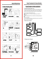
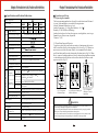
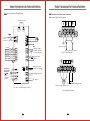
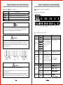
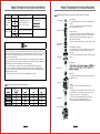
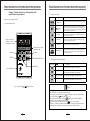


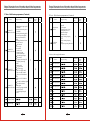
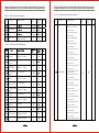
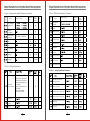
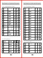
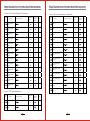

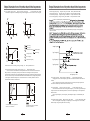

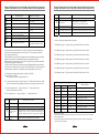
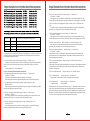


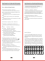
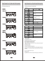
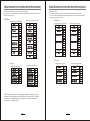
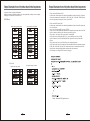
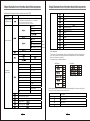
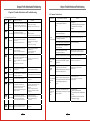
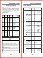
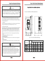
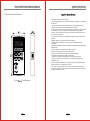

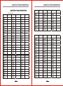

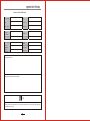

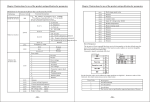
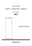


![[PF03] User manual for WHITE-COLOR DOT - Auto](http://vs1.manualzilla.com/store/data/005728816_1-b07d7d3c2bb75a06da64907106241247-150x150.png)


![[PF03] User manual for RED DOT CLUSTERS(EN) - Auto](http://vs1.manualzilla.com/store/data/005713867_1-90b7ac4617a5dc924635c3e0ee039806-150x150.png)