1
TELSEC® RM/WM
Models 800, 1500 & 2000
(Web Enabled Version)
User’s Manual
Quest Controls, Inc.
208 9th Street Dr. West
Palmetto, FL 34221
www.questcontrols.com
Phone: (941) 729-4799
Fax: (941) 729-5480
Email: [email protected]
Rev 2.0 9/9/09
TELSEC® 2000/1500 RM/WM
User’s Manual
Table Of Contents
CHAPTER 1 – INTRODUCTION
1
CHAPTER 2 - PRODUCT SPECIFICATIONS
2
2.1 SCOPE
2.2 DESCRIPTION
2.2.1 FEATURES:
2.3 GENERAL REQUIREMENTS
2.3.1 HARDWARE ARCHITECTURE:
2.3.2 BASIC PRODUCT (TELSEC® RM/WM):
2.3.3 RACK MOUNT:
2.3.4 WALL MOUNT:
2.3.5 POWER SUPPLY:
2.3.6 EXPANSION MODULE:
2.3.7 EXPANSION CARD:
2.3.8 ALARM PORTS AND PRE-CONNECTORIZED BLOCK
2.4 COMMUNICATIONS MODULES
2.4.1 LOCAL SERIAL PORT:
2.4.2 MODEM PORT:
2.4.3 ETHERNET PORT:
2.4.4 ALARM REPORTING:
2.4.5 DIAL-IN PASSWORD SECURITY:
2.5 SPECIFICATIONS
2.5.1 TELSEC® 1500/2000:
2.5.2 TELSEC® 800:
2.5.3 TELSEC® EXPANSION MODULE:
2
2
2
2
2
2
2
2
3
3
3
3
3
3
3
3
3
4
4
4
5
5
CHAPTER 3 - INSTALLATION INSTRUCTIONS
6
3.1 SCOPE:
3.2 UNPACKING THE SYSTEM:
3.2.1 TELSEC® RM INCLUDED COMPONENTS
3.2.2 TELSEC® WM INCLUDED COMPONENTS
3.3 ADDITIONAL MATERIAL AND EQUIPMENT:
3.3.1 INSTALLATION MATERIALS:
3.3.2 TOOLS
3.4 MOUNTING THE TELSEC® RM:
3.4.1 CONNECTING MOUNTING BRACKETS
3.4.2 ATTACHING THE TELSEC® RM TO THE RACK
3.5 MOUNTING THE TELSEC® WM
3.5.1 CONNECTING THE MOUNTING PLATES
6
6
7
7
7
7
7
7
8
8
9
9
Rev 2.0 9/9/09
i
TELSEC® 2000/1500 RM/WM
User’s Manual
Table Of Contents
3.5.2 ATTACHING TO THE WALL
3.6 MOUNTING FIELD TERMINAL DEVICES:
3.6.1 WIRE WRAP BLOCK
3.6.2 KRONE PUNCH BLOCK
3.6.3 CONTROL INTERFACE MODULE (CIM)
3.6.4 INPUT/OUTPUT MATRIX
3.7 CONNECTING TO THE COM PORTS
3.7.1 RS232 CONNECTION
3.7.2 MODEM CONNECTION
3.8 KEYPAD/CARD READER
3.8.1 WIRING THE CARD READER
3.9 CONNECTING TO DC POWER SUPPLY
3.9.1 POWER WIRING
3.9.2 INSTALL FERRITE COIL
3.9.3 POWERING-UP THE TELSEC®
3.10 TYPICAL CONTROL DIAGRAMS
3.10.1 TYPICAL CEV CONTROL AND MONITORING
3.10.2 HUT CONTROL AND MONITORING
3.10.3 WALK IN CABINET (WIC)
3.10.4 REMOTE CABINET MONITORING
3.10.5 TELSEC 800 WITH 4 PORT SERIAL BRIDGE
3.10.6 CARD ACCESS CONTROL
3.10.7 FOUR PORT CARD ACCESS CONTROL
9
9
10
10
10
11
13
13
13
13
14
15
15
15
16
16
17
20
23
26
28
29
32
CHAPTER 4 - APPLICATION
33
4.1
4.2
4.3
4.4
4.5
4.6
4.7
4.8
4.9
33
34
35
36
38
39
40
41
42
OVERVIEW
CEV WITH TWO AIR CONDITIONERS
HUT WITH 2 AC UNITS
CABLE HEAD END
OTN HUB WITH 2 AC UNITS
CEC/CUE WITH 2AC
REMOTE CABINET MONITORING
CEV WITH TELEPHONY AND BATTERY TEMPERATURE MONITORING
BLANK POINTS LIST FORMS
CHAPTER 5 ETHERNET INTERFACE
43
5.1 CONNECTING TO THE TELSEC
5.2 SETTING THE TELSEC IP ADDRESS
5.2.1 SETTING THE IP ADDRESS WITH THE PING COMMAND
5.3 TELSEC WEB SERVER
5.3.1 SECURITY
43
43
43
44
44
Rev 2.0 9/9/09
ii
TELSEC® 2000/1500 RM/WM
User’s Manual
Table Of Contents
5.3.2 WEB PAGE NAVIGATION
5.3.3 THE HOME PAGE
5.3.4 INPUT STATUS PAGE
5.3.5 OUTPUT STATUS PAGE
5.3.6 BYPASSING OUTPUTS
5.3.7 SET POINT STATUS PAGE
5.3.8 CHANGE SET POINT
5.3.9 ALARM STATUS
5.3.10 ALARM HISTORY
5.3.11 SCHEDULE STATUS PAGE
5.3.12 CHANGING/VIEWING TIME SCHEDULES
5.3.13 CHANGE/VIEW DATE SCHEDULES
5.3.14 LOGGING PAGE
5.3.15 SETTING THE SYSTEM CLOCK
5.3.16 ALARM DISPATCH PAGE
5.3.17 WEB SERVER SETUP
5.3.18 ACCESS CONTROL
5.3.19 COMMAND LINE
5.4 SNMP OVERVIEW
5.4.1 SNMP SETS AND GETS
5.4.2 SNMP TRAPS
5.4.3 CARD ACCESS NOTIFICATIONS
5.5 SERIAL PASS-THROUGH
45
45
46
47
49
50
50
51
52
52
53
54
54
55
56
59
62
64
65
65
66
68
69
CHAPTER 6 – REVIEWING INFORMATION AND GENERAL OPERATION 71
6.1 GETTING ON-LINE:
6.1.1 A WORD ABOUT PASSWORDS:
6.1.2 MODEM:
6.1.3 COMMUNICATIONS TERMINAL:
6.1.4 TELNET OVER ETHERNET:
6.1.5 FRONT PANEL:
6.2 REVIEW COMMAND:
6.2.1 COLUMN HEADER DEFINITIONS:
6.2.2 REVIEW UIN:
6.2.3 REVIEW RLY
6.2.4 REVIEW DAT
6.2.5 REVIEW TOD
6.2.6 REVIEW EQU
6.2.7 REVIEW VAR
6.2.8 REVIEW SPT
6.2.9 REVIEW DOR
6.2.10 REVIEW BAT
Rev 2.0 9/9/09
71
71
71
72
72
72
72
73
73
73
73
73
74
74
74
74
74
iii
TELSEC® 2000/1500 RM/WM
User’s Manual
Table Of Contents
6.2.11 REVIEW ALARM
6.2.12 REVIEW ALARM LOG
6.2.13 REVIEW LOG:
6.2.14 REVIEW BUS
6.3 BYPASS COMMAND:
6.4 CLEAR COMMAND:
6.5 HANGUP COMMAND:
6.6 SEARCH COMMAND:
6.7 SPECIAL COMMAND CHARACTERS:
6.7.1 ABORT KEYS :
6.7.2 FLOW CONTROL:
6.8 SETTING UP A MODEM ALARM RECEIVER
6.9 TELSEC® POINT ACRONYMS AND QUANTITIES
74
74
75
75
75
76
76
77
77
77
77
77
78
CHAPTER 7 – BASIC PROGRAMMING COMMANDS
79
7.1 GENERAL INFORMATION
7.2 COMMAND SYNTAX
7.2.1 CONVENTIONS:
7.2.2 A WORD ABOUT NAMES:
7.2.3 HELP COMMAND:
7.2.4 SHORT CUTS
7.3 DEFINE COMMAND:
7.3.1 DEFINE UIN:
7.3.2 DEFINE RLY:
7.3.3 DEFINE KEY:
7.3.4 DEFINE DAT:
7.3.5 DEFINE TOD:
7.3.6 DEFINE EQU:
7.3.7 DEFINE VAR:
7.3.8 DEFINE SPT:
7.3.9 DEFINE DOR:
7.3.10 DEFINE ANM:
7.3.11 DEFINE MSG:
7.3.12 DEFINE BAT:
7.3.13 DEFINE CARD:
7.4 SET COMMAND:
7.4.1 SET ID
7.4.2 SET CLOCK:
7.4.3 SET PSWD:
7.4.4 SET DLS (DAYLIGHT SAVINGS):
7.4.5 SET BUS:
7.4.6 SET MAIL:
79
79
79
79
79
80
80
80
82
83
83
84
85
85
85
85
85
86
87
87
88
88
88
89
90
90
91
Rev 2.0 9/9/09
iv
TELSEC® 2000/1500 RM/WM
User’s Manual
Table Of Contents
7.4.7 SET SCALE:
7.4.8 SET LIST:
7.4.9 SET PROGRAM:
7.4.10 SET COM:
7.4.11 SET FALSE:
7.4.12 SET APPEND:
7.4.13 SET CID:
7.5 LIST COMMAND:
7.6 REMOVE COMMAND:
7.7 NAME COMMAND:
7.8 COPY COMMAND:
91
92
92
92
93
95
95
96
97
97
97
CHAPTER 8 – EQUATION LANGUAGE
99
8.1 GENERAL REMARKS
8.2 THE COMPONENTS OF EQUATIONS
8.2.1 FORMULAS:
8.2.2 ASSIGNMENTS:
8.2.3 STATEMENTS:
8.3 THE FORM OF EQUATIONS
8.3.1 GENERAL FORMAT:
8.3.2 CONDITIONAL EQUATIONS:
8.3.3 ONE-TIME EQUATIONS:
8.3.4 TYPING NUMBERS:
8.3.5 TYPING INTERVALS:
8.3.6 ARITHMETIC:
8.3.7 OPERATORS:
8.3.8 FUNCTIONS:
8.3.9 INPUTS IN EQUATIONS:
8.3.10 CONDITIONALS:
8.3.11 COMPARISONS:
8.3.12 THE FOR KEYWORD:
8.3.13 SWITCHING RELAYS:
8.3.14 WAITING:
8.3.15 WAIT UNTIL:
8.3.16 ASSIGNMENT:
8.3.17 SET ELEMENT TO FORMULA:
8.3.18 VARIABLES:
8.3.19 SETPOINTS:
8.3.20 ADDITIONAL WAYS TO CHANGE VALUES:
8.4 TIMERS AND COUNTERS
8.4.1 DIGITAL OUTPUT POINTS (RLY):
8.4.2 DIGITALLY DEFINED INPUT POINTS (UIN):
Rev 2.0 9/9/09
v
99
99
99
99
99
100
100
100
100
100
101
101
101
101
102
102
103
104
104
104
105
105
105
105
106
107
108
108
108
TELSEC® 2000/1500 RM/WM
User’s Manual
Table Of Contents
8.5 SEND COMMAND:
8.6 ALARM EQUATIONS:
8.7 FREEFORM LOGGING:
8.8 ADVANCED EQUATION FUNCTIONS:
8.8.1 ENABLE/DISABLE:
8.8.2 RETURNING VALUES:
8.8.3 MULTIPLE CONDITIONALS:
8.8.4 STATEMENT BLOCKS:
8.8.5 NESTED IFS:
8.8.6 RATE AND AVERAGE RATE FUNCTION:
8.8.7 PULSE COMMAND:
8.8.8 COM PORT STATUS:
8.8.9 BATTERY MONITOR STATUS:
8.9 SHORTCUTS:
8.9.1 AVOIDING REPEAT EFFECTS:
8.9.2 REPEAT EFFECTS MAY NOT MATTER.
8.9.3 DETAILED TIMING:
8.9.4 USE OF MEMORY:
8.9.5 CHECKSUMS:
8.10 ESTABLISHING CRITERIA TO WRITE EQUATIONS:
8.11 UPLOADING PROGRAMS:
8.11.1 XMODEM FILE TRANSFER
8.11.2 ASCII TEXT TRANSFER
8.11.3 SAVING PROGRAMS TO NON-VOLATILE MEMORY
108
109
110
110
110
111
111
112
112
112
113
113
114
115
116
116
117
117
117
118
121
121
121
121
CHAPTER 9 – ACCESS CONTROL
122
9.1 OVERVIEW
9.2 USING THE ACCESS CONTROL SYSTEM
9.2.1 DEFINE THE FEEDBACK DIGITAL POINT
9.2.2 DEFINE YOUR DIGITAL OUTPUT:
9.2.3 DEFINE THE DOR POINT:
9.2.4 DEFINE VALID ACCESS CARDS:
9.2.5 SETTING SITE CODE AND BIT FORMAT:
9.2.6 USING KEYPAD CODES:
9.3 SYSTEM MESSAGES
9.3.1 REVIEWING ACCESS CONTROL INFO
9.4 LISTING ACCESS CONTROL INFORMATION
9.5 REMOVING CARDS
122
122
122
122
122
123
124
124
125
125
125
126
Rev 2.0 9/9/09
vi
TELSEC® 2000/1500 RM/WM
User’s Manual
Table Of Contents
CHAPTER 10 - FRONT PANEL DISPLAY AND KEYPAD
127
10.1 OVERVIEW:
10.2 BASIC PRINCIPLES
10.2.1 PASSWORDS:
10.2.2 LOGGING OFF:
10.2.3 CHOICES:
10.2.4 ABORTING:
10.2.5 EQUATION GENERATED SENDS:
10.2.6 AUTOMATIC DIGITAL INPUT ALARMS:
10.2.7 REVIEWING INFORMATION:
10.3 PROGRAM MODIFICATION:
10.3.1 SET POINT MODIFICATION:
10.3.2 BYPASSING OUTPUTS:
10.3.3 SETTING THE CLOCK:
127
127
127
128
128
128
128
129
129
129
129
130
132
CHAPTER 11 - SERVICE
133
11.1
11.2
11.3
11.4
11.5
11.6
11.7
133
134
135
136
137
138
139
TROUBLE SHOOTING PROBLEMS:
CHART 1 – POWER PROBLEMS
CHART 2 – SYSTEM FAILURE
CHART 3 – NO DIAGNOSTIC OUTPUT
CHART 4 – MODEM OUTPUT
CHART 5 –ERRONEOUS TROUBLE REPORTS
CHART 6 - OTHER PROBLEMS
WARRANTY INFORMATION
140
GLOSSARY
141
Rev 2.0 9/9/09
vii
TELSEC® 2000/1500 RM/WM
User’s Manual
Chapter 1 – Introduction
Congratulations on the purchase of your new TELSEC® 2000/1500 RM/WM product!
The TELSEC® is a state-of-the-art electronic monitor and controller providing you with an
integrated solution for the facility management of your remote sites such as CEVs, CUEs,
Shelters/Huts, Cabinets, Customer Prem Sites, Central Offices, Switching & Data Centers, and
Head-Ends. Acting as your smart eyes and ears at the remote site, the TELSEC® is capable of
performing your HVAC Control and Monitoring, Environmental Monitoring, Power Capacity and
Battery Monitoring, Generator Monitoring, Telephony Equipment Monitoring, Cable Pressure &
Air Flow Monitoring, Tower Light Monitoring, and Door Access Control --- all in ONE NEBS
LEVEL III approved product.
This User’s Manual is intended to provide you with the information you need to get
started with the TELSEC®, understand its specifications, how to install it, how to apply it, how to
operate and program it, and how to service and maintain it plus much more. Please contact us at
Quest if you have product questions or suggestions to improve this User’s Manual.
COPYRIGHT NOTICE
Copyright © 2000-2008 by Quest Controls Inc (QUEST). The material discussed in this
publication is the proprietary property of QUEST. QUEST retains all rights to reproduction and
®
distribution of this publication. TELSEC is a registered trademark of QUEST.
Specifications are subject to change without notice.
-1Rev 2.0 9/9/09
Chapter 1 – Introduction
TELSEC® 2000/1500 RM/WM
User’s Manual
Chapter 2 - Product Specifications
2.1
Scope
®
Chapter 3 describes the general specifications of the TELSEC 800, 1500 and 2000
environmental control, monitoring and alarming system.
It describes only the general
specifications of the system and does not define the detailed functional specifications.
2.2
Description
2.2.1 Features:
®
The TELSEC system is designed to collect wet or dry discrete alarms from telephone
equipment, controlling, monitoring and alarming critical operating equipment such as HVAC,
power plant, intrusion, fire alarms and any other alarms that are indicated by wet or dry contact
closure. All environment conditions can be monitored through discrete alarm contacts or via
analog input sensors. In addition, the system provides security access control for the facility.
®
The TELSEC is capable of formatting discrete alarm data into SNMP traps or text messages
®
and transmitting the alarm messages via the TELSEC ’s built-in modems, through the optional
PPP modem module or through the optional Ethernet module.
2.3
General Requirements
2.3.1 Hardware Architecture:
®
The TELSEC is a microprocessor-based controlling, monitoring, data collecting and alarm
reporting system designed for the management and effective operation of remote facility assets.
A fully configured product can monitor as many as 64 discrete inputs and provide 32 control
contact points.
2.3.2 Basic Product (TELSEC® RM/WM):
®
The basic product is available in two styles: a rack mountable shelf (TELSEC RM) and wall
®
mountable enclosure (TELSEC WM). The single board layout design of the master unit
incorporates the power supply, memory and serial and modem communication ports with up to32
universal inputs and 16 control contact points per enclosure.
2.3.3 Rack Mount:
®
The TELSEC RM shelf is designed for a 19-inch or 23-inch standard telephone type rack
mounting utilizing reversing brackets to provide flexibility for positioning the system on the rack.
The front panel includes: a 32-character display; 8-button keypad; and a RS232 connector (craft
port) for local serial input/output. The rear of the product includes: a green LED to indicate power
on or off; two 50-pin connectors for inputs/outputs; connectors for power, expansion and
communication ports; and a connector for card access control.
2.3.4 Wall Mount:
®
The TELSEC wall mount enclosure is designed to mount to the wall of any type facility. The unit
comes with two mounting plates, which should be attached to the back of the unit. The front
panel includes a 32-character display and 8-button keypad. The bottom includes a green LED to
indicate power on or off, connectors for power and expansion and communication ports, as well
as a connector for card access control. The top includes two 50-pin connectors for input/outputs
and a RS232 connector (craft port) for serial input/output.
–2–
Rev 2.0 9/9/09
Chapter 2 – Product Specifications
TELSEC® 2000/1500 RM/WM
User’s Manual
2.3.5 Power Supply:
®
The TELSEC is powered by a negative 48 VDC battery or an equivalently-rated 48 VDC source.
The system can also be powered from +24 VDC. The green LED on the lower right of the back
panel will be lighted continuously to indicate the system is connected to the source voltage.
Standard 2-position screw terminal provides interconnection of the power source and a built-in resettable fuse provides surge and overload protection.
2.3.6 Expansion Module:
The TELSEC® 2000 expansion module is a remote module that will expand a basic TELSEC®
input and output capability. The module provides an additional 32 universal inputs and 16 control
contacts. This unit comes in either rack mount or wall mount configuration and plugs into the
TELSEC® RM or WM through a 3 wire network connection. The Expansion module can be
located up to 1000 feet (300M) from the main TELSEC® system and can be either Rack mounted
(RME) or wall mounted (WME).
2.3.7 Expansion Card:
The TELSEC® 1500 expansion card is a plug-on module that will expand a basic TELSEC® 1500
to accommodate an additional 16 universal inputs and 8 outputs. This module is typically
installed in the factory but is designed to be field upgradeable, if required.
2.3.8
Alarm Ports and Pre-Connectorized Block
Type ‘T’ Pre-connectorized Terminal Blocks, Part #300718: The terminal block is designed to be
used with all terminations required for dry and wet/dry alarms. It is a ‘Telzon’ type connectorized
terminal block and has 4 predetermined 50-pin TELCO connectors on the rear and 8 horizontal
rows of 200 wire-wrap pins for cross connecting the alarm leads from the specific device being
monitored.
2.4
Communications Modules
2.4.1 Local Serial Port:
The local serial port supports the asynchronous serial communications located on the front of the
rack mount unit and the side of the wall mount unit.
2.4.2 Modem Port:
The TELSEC® has an optional plug-in modem that provides up to 56K baud (optional)
asynchronous communications on the public switch network. The modem is used for remote
maintenance and/or alarm reporting to the NMA network.
2.4.3 Ethernet Port:
®
The TELSEC system has an optional 10Base-T Ethernet port for alarming via SNMP traps. All
status can be viewed by either a Web Browser (HTTP), SNMP Gets or command line via a Telnet
session.
2.4.4 Alarm Reporting:
The TELSEC® has the ability to dial out to as many as four pre-selected phone numbers
whenever an alarm or an alarm clear message must be reported. The modem card also has the
ability to receive a call from a remote modem and function as the local alarm port. Once the
connection is established (either by receiving a call or initiating a call), the modem card provides
an asynchronous communications link where TL1 commands can be entered and alarm/clear
messages can be received.
–3–
Rev 2.0 9/9/09
Chapter 2 – Product Specifications
TELSEC® 2000/1500 RM/WM
User’s Manual
2.4.5 Dial-in Password Security:
In order to prevent unauthorized access to the TELSEC® through modem connection, a password
prompt will appear anytime a successful connection is made. In response to the prompt, the user
must enter a correct password followed by a carriage return. If the user fails to enter a valid
password in one attempt, the modem will be disconnected. The user has 10 seconds to enter a
valid password, otherwise the TELSEC® will consider the lack of response to be an invalid
password and the modem card will disconnect. When a valid password is entered, the TELSEC®
will respond with a login message and will be ready to accept commands.
2.5
Specifications
TELSEC® 1500/2000:
2.5.1
Specifications
Part Number
TELSEC® 1500RM
TELSEC® 2000RM
TELSEC® 1500WM
TELSEC® 2000WM
150619
150618
150617
150612
Mounting
Number of Universal Inputs
Number of Outputs
Rack mount 19" or 23"
Wall mount
16
32
16
32
8 NO
16 NO
8 NO
16 NO
Input Types
All universal inputs can be analog (0-5 VDC or 0-20mA), dry contact closure or wet contact (3-75 VDC)
Output Types
Normally Open (NO), 1 amp at 30 VDC, 0.3 amps at 60 VDC, 0.5 amps at 125 VAC
Card Access
Supports industry standard Wiegand format, proximity or card swipe readers. Up to 4 doors can be controlled.
Control 4 doors with 3500 cards. Logs 500 most recent events
Power
±18 to 65 VDC, 0.5 amps. Optional 120/110 VAC, 60Hz, 0.25 amps
Front Panel
Built-in programming panel with 8 keys and a 32-character backlit LCD Display
Modem (with Caller ID)
56K modem with Caller ID. Up to 24 phone numbers can be programmed to limit access to the system.
Note: Caller ID service must be present on the phone line
Serial Port
One asynchronous db9 RS232 serial port. Programmable for speed, parity, and bit format
Network Interface (option)
LAN
Protocols Supported
Serial Pass through
Ethernet 10BaseT with RJ45 connector
TCP/IP, Telnet, HTTP, SMTP, SNMP v1, v2c, Sets, Gets, Traps & Informs
Provides Telnet connectivity over Ethernet for three RS232 asynchronous serial devices.
Logging
Logs all inputs, outputs, and alarms, up to 16,000 points
Software
Supports any off-the-shelf terminal communication software (e.g. Procomm®, HyperTerminal®) or Web browser (e.g. Internet
Explorer® 6+, Firefox® 1.5+)
I/O Terminals
Two (2) 50 PIN Amphenol connectors for outputs, discrete and analog inputs.
Supports 2 wire (tip & ring), connections for each point using 25 pair cable
Battery
Long-life lithium. 10-year shelf, 1.5 years under load
Temp/Humidity
Sensor Accuracy
Temp: ±1°F (±-0.5°C), Humidity: ±2% of range. Temperature & Humidity sensors included
Ambient Operating Temp
-40 to 180°F (-40 to 82°C), 0-95% RH Non-condensing
Certification
NEBS Level III Approved, UL Listed, CE
–4–
Rev 2.0 9/9/09
Chapter 2 – Product Specifications
TELSEC® 2000/1500 RM/WM
User’s Manual
TELSEC® 800:
2.5.2
Specifications
TELSEC® 800
Part Number
150679; for SNMP/WEB browser option, order part number: 150769
Mounting
Rack mount 19" or 23", or on cabinet door
Inputs
8 universal inputs: analog (0-5 VDC or 0-20 mA), dry contact closure or wet contact (3-75 VDC)
Outputs
8 Normally Open (NO), 1 amp at 30 VDC, 0.3 amps at 60 VDC, 0.5 amps at 125 VAC
Card Access
Supports industry standard Wiegand format, proximity or swipe card readers. Up to 3500 cards can be programmed
per site. Logs 500 most recent events
Power
±18 to 65 VDC, 0.5 amps. Optional 110 VAC/220 VAC, 60 Hz, 0.5 amp
Modem (with Caller ID)
56K modem with Caller ID. Up to 24 phone numbers can be programmed to limit access to the system.
Note: Caller ID service must be present on the phone line
Serial Port
One asynchronous db9 RS232 serial port. Programmable for speed, parity, and bit format
Network Interface (option)
LAN
Protocols Supported
Serial Pass through
Ethernet 10BaseT with RJ45 connector
TCP/IP, Telnet, HTTP, SMTP, SNMP v1, v2c, Traps/Informs
Provides Telnet connectivity over Ethernet for three RS232 asynchronous serial devices.
Logging
Logs all inputs, outputs, and alarms, up to 16,000 points
Software
Supports any off-the-shelf terminal communication software (e.g. Procomm®, HyperTerminal®) or Web browser (e.g.
Internet Explorer® 6+, Firefox® 1.5+)
I/O Terminals
A single 50-pin Amphenol® connector for outputs, discrete and analog inputs. Supports 2 wire (tip and ring),
connections for each point using 25 pair cable
Battery
Long-life lithium. 10-year shelf, 1.5 years under load
Temp Sensor Accuracy
±1°F (±0.5°C), temp sensor s
Ambient Operating Temp
-40 to 180°F (-40 to 82°C), 0-95% RH Non-condensing
Certification
NEBS Level III Approved, UL Listed, CE
Dimensions
1.75" H x 13.25" W x 9.5" D (45 mm x 337 mm x 241 mm)
Shipping Weight
4 lbs (1.81 kg)
2.5.3
TELSEC® Expansion Module:
Specifications
TELSEC® Expansion Module
Part Number
150640 for Rack Mount , 150724 for Wall Mount
Mounting
Rack mount 19" and 23" or Wall Mount
Inputs
32 universal inputs: analog (0-5 VDC or 0-20 mA), dry contact closure or wet contact (3-75 VDC)
Outputs
16 Normally Open (NO), 1 amp at 30 VDC, 0.3 amps at 60 VDC, 0.5 amps at 125 VAC
Certification
NEBS Level III Approved, UL Listed, CE
Dimensions
Rack mount - 17” W X 10.5” D X 1.75” H (43.1cm W X 26.7cm D X 4.5cm H)
Wall mount - 11”H X 11”W X 2”D (279 mm X 279 mm X 51 mm)
Shipping Weight
Rack mount - 6 lbs. (2.7 kg.)
Wall mount - 4 lbs. (1.8 kg.)
–5–
Rev 2.0 9/9/09
Chapter 2 – Product Specifications
TELSEC® 2000/1500 RM/WM
User’s Manual
Chapter 3 - Installation Instructions
3.1
Scope:
®
This Chapter describes the hardware installation, for the TELSEC Rack Mount and Wall Mount
®
(RM/WM). For a general description of the TELSEC , refer to Chapter 2 - Product
®
Specifications. The TELSEC comes in two basic hardware configurations. The TELSEC® RM
®
(figure 1) is a rack-mounted unit designed to fit in either a 19” or 23” rack. The TELSEC WM
(figure 1) is a wall-mounted unit designed to mount to any type of wall surface that can support
the product.
Figure 1 TELSEC® RM Rack Mount
Figure 2 TELSEC® WM Wall Mount
3.2
Unpacking the System:
®
The TELSEC may be ordered in a number of configurations to suit a wide variety of
installations. All options ordered are tested and installed at the factory, and the complete system
is ready for installation when it is removed from the shipping carton. This carton and the
packaging material should be retained in case it becomes necessary to return the unit to the
®
factory for repair. In addition to the TELSEC unit, the following items will be found inside the
carton:
–6–
Rev 2.0 9/9/09
Chapter 3 – Installation Instructions
TELSEC® 2000/1500 RM/WM
User’s Manual
•
•
•
•
•
TELSEC® RM Included Components
Two (2) reversible rack-mounting brackets.
Mounting Hardware four each of: #8 screws, #8 lock washers,#8 flat washers,#12
screws, #12 internal tooth star washers and #12 flat washers.
Two 5.5” tie wraps for securing the 50 pin amphenol cables to the input/output
connectors.
One Ferrite coil for incoming power noise suppression.
Humidity/Temp sensor with enclosure and mounting hardware.
Phone cords. Optional: one for each modem provided with the unit.
User’s Manual on Tech Doc CD.
Configuration sheet listing all serial numbers and options installed in the unit.
3.2.2
•
•
•
•
•
•
•
•
TELSEC® WM Included Components
Two mounting brackets.
Mounting Hardware four each #6 flat head screws.
One 5.5” tie wraps for securing the 50 pin amphenol cable to the input/output connectors.
One Ferrite coil for incoming power noise suppression.
Humidity/Temp sensor (removable, but comes mounted to bottom of chassis).
Phone cords. Optional: one for each modem provided with the unit.
User’s Manual on Tech Doc CD.
Configuration sheet listing all serial numbers and options installed in the unit.
3.2.1
•
•
•
3.3
Additional Material and Equipment:
The following items may be required for installation, which are in addition to the items provided by
Quest:
3.3.1 Installation Materials:
• Cable and Shielded cable
• Butt splices
• Cable ties
• Bushings/strain relief
• Anchors, screws etc.
3.3.2 Tools
• Hand Tools - Screwdrivers, Hammer, wire cutters, pliers, etc.
• Wire wrap & unwrap tools or punch tool
• Crimping tool
• Hammer drill and drill bits (if wall mounting devices)
3.4
Mounting the TELSEC® RM:
®
The TELSEC is shipped with two (2) angle brackets, which allow the system to be mounted in
either a 19-inch or 23-inch equipment rack. The brackets are reversible, with a long side and a
short side. To mount the system in a 19-inch rack, (See Figure 3.) the long side of a bracket is
®
attached to each side of the TELSEC (using the #8 mounting hardware provided) and the short
sides of the bracket are attached to the equipment rack (using the #12 mounting hardware
provided). To accommodate a 23-inch rack, the brackets are reversed, with the short sides being
®
attached to the TELSEC and the long sides attached to the rack. (See Figure 4.)
–7–
Rev 2.0 9/9/09
Chapter 3 – Installation Instructions
TELSEC® 2000/1500 RM/WM
User’s Manual
Figure 3 Bracket Orientation for 19-inch Equipment Rack
Figure 4 Bracket Orientation for 23-inch Equipment Rack.
3.4.1 Connecting Mounting Brackets
There are three (3) sets of two (2) holes on each side of the System console. (See Figure 4
above.) Any of these sets may be used to attach the mounting brackets to the system. Use the
#8 screw with lock washer and flat washer to secure the bracket to the side of the chassis in two
places. USE ONLY THE ATTACHING SCREWS PROVIDED, AND DO NOT ATTACH THE
BRACKETS WITHOUT USING THE WASHERS PROVIDED – Screws longer than those
provided to mount the brackets might engage the cables or interface board inside the unit,
resulting in damage to one or more system components. Clearance on the top and bottom is not
a concern because the ventilation perforations are on the side of the console.
3.4.2 Attaching the TELSEC® RM to the Rack
Use the #12 hardware provided to mount the unit to the rack. The Mounting ears will
accommodate either 1 inch or 1 ¼ mounting hole spacing. Use a #12 screw with flat washer in
front of the mounting bracket and the #12 star washer between the bracket and rack frame to
create a good frame ground. Mount with two screws per side.
–8–
Rev 2.0 9/9/09
Chapter 3 – Installation Instructions
TELSEC® 2000/1500 RM/WM
User’s Manual
3.5 Mounting the TELSEC® WM
The unit is designed to mount to a wall without having to remove the cover. The system
comes with two mounting plates to mount the unit to wall or to the front of an electrical
enclosure.
3.5.1 Connecting the Mounting Plates
Use the four #6 flat head screws to secure the mounting plates to the back of the chassis.
3.5.2 Attaching to the Wall
Use the appropriate anchors (not provided) for the type of wall you are mounting the TELSEC®
on. The mounting holes will accommodate a #8 screw. It is recommended that the panel be
mounted so that the display can be seen at eye level Approx six feet from the floor.
3.6
Mounting Field Terminal Devices:
®
The TELSEC RM/WM supports four methods for field wiring of inputs and outputs. The wire
wrap block and Krone punch block are used when rack mounting of field wiring is required and
the Control Interface Module (CIM) is used for a wall mounted field termination device. The fourth
method for field wiring is to direct wire from the alarm point with a cable that has a 50 pin
®
amphenol connector to connect to the TELSEC . All four methods ultimately connect the field
®
wiring to the 50 pin ports on the TELSEC . Some application may require that a CIM module is
used for the first 16 inputs and 8 outputs and a wire wrap block is used for inputs 17-32 and
outputs 9-16. See Figure 5
Use the wire wrap block for alarming and
control when rack mounting is desired
TELSEC WIRE WRAP
BLOCK
A
B
C
D
B
NMA
RS232
NMA CRAFT
RJ11 RJ11 EXP. BUS
(+) POS
(-) NEG
C2
+12v
+5v
D0
D1
GND
EGND
C1
TELSEC 2000RM REAR VIEW
POWER
A
I/O
S1
S2
S3
S0
CARD ACCESS
GND
OPTIONAL WIRING OF 50 PIN CABLE
TO PORT A OF WIRE WRAP BLOCK
INSTEAD OF USING CIM
TELSEC CIM
Use the CIM for environmental alarming
and control or when rack space is not
available for a wire wrap block
Figure 5 Field wiring options.
–9–
Rev 2.0 9/9/09
Chapter 3 – Installation Instructions
TELSEC® 2000/1500 RM/WM
User’s Manual
3.6.1 Wire Wrap Block
Quest’s Wire Wrap block Figure 6 (p/n 300718) can be used to terminate all field wiring. The
block will support four 50-pin ports for a maximum of 64 inputs and 32 outputs. Mount the block
to the rack using the supplied bracket and then use a 25 pair cable (p/n 300705) to interconnect
®
the ports on the block to the TELSEC . Make sure the connecter is seated properly into the
connector at each end and secured with the locking screw and tie wrap.
WIRE WRAP BLOCK FOR TERMINATION OF FIELD WIRING
1
2
3
4
5
6
7
8
9
10 11 12 13 14 15 16 17 18 19 20 21 22 23 24 25
2
4
6
8
10
12
14
16
Figure 6 Wire Wrap Block
3.6.2 Krone Punch Block
A punch block (p/n 300158) can be used for either wall or rack mounting of field terminations.
Use the included mounting bar for mounting to a rack or mount with appropriate anchors (not
provided) to a wall. Each block can support two ports for a total of 32 inputs and 16 outputs.
®
Connect the punch block to the TELSEC with 25 pair cable (p/n 300705). Make sure the
connector is seated properly into the connector at each end and secured with the locking screw
and tie wrap. See figure 7.
BL/W
W/BL
OR/W
W/OR
GR/W
W/GR
BR/W
W/BR
SL/W
W/SL
BL/R
R/BL
OR/R
R/OR
GR/R
R/GR
BR/R
R/BR
SL/R
R/SL
BL/BK
BK/BL
OR/BK
BK/OR
GR/BK
BK/GR
BR/BK
BK/BR
SL/BK
BK/SL
BL/Y
Y/BL
OR/Y
Y/OR
GR/Y
Y/GR
BR/Y
Y/BR
SL/Y
Y/SL
BL/V
V/BL
OR/V
V/OR
GR/V
V/GR
BR/V
V/BR
SL/V
V/SL
KRONE BLOCK
BL/W
W/BL
OR/W
W/OR
GR/W
W/GR
BR/W
W/BR
SL/W
W/SL
BL/R
R/BL
OR/R
R/OR
GR/R
R/GR
BR/R
R/BR
SL/R
R/SL
BL/BK
BK/BL
OR/BK
BK/OR
GR/BK
BK/GR
BR/BK
BK/BR
SL/BK
BK/SL
BL/Y
Y/BL
OR/Y
Y/OR
GR/Y
Y/GR
BR/Y
Y/BR
SL/Y
Y/SL
BL/V
V/BL
OR/V
V/OR
GR/V
V/GR
BR/V
V/BR
SL/V
V/SL
Figure 7 Krone Punch Block
3.6.3 Control Interface Module (CIM)
The CIM (p/n 150642) is used for when wall mount mounting of field wiring is desired or if the field
wiring being used is stranded or larger gauge (12AWG to 22AWG) wire. Each CIM supports 16
inputs and 8 outputs, and has a 50 pin amphenol connector on the bottom to allow for connection
to the TELSEC® via a 25 pair cable (p/n 300705). Make sure the connecter is seated properly
into the connector at each end and secured with the locking screw and tie wrap. See figure 8.
– 10 –
Rev 2.0 9/9/09
Chapter 3 – Installation Instructions
TELSEC® 2000/1500 RM/WM
User’s Manual
INPUTS
OUTPUTS
1
2
3
4
5
6
7
8
IN 1-
IN 9-
IN 1+
IN 9+
IN 2-
IN 10-
IN 2+
IN 10+
IN 3-
IN 11-
IN 3+
IN 11+
IN 4-
IN 12-
IN 4+
IN 12+
IN 5-
IN 13-
IN 5+
IN 13+
IN 6-
IN 14-
IN 6+
IN 14+
IN 7-
IN 15-
IN 7+
IN 15+
IN 8-
IN 16-
IN 8+
IN 16+
GND
GND
GND
GND
Figure 8 CIM Board
3.6.4 Input/Output Matrix
Figure 9 below is a matrix showing the wire color for each input and output and the pinout for the
wire wrap block. Use this chart to determine where to land each field wire whether you are using
a CIM (look at input/output number), wire wrap (row/column pin number, Krone block (match wire
color) or direct termination to cable (match wire color).
– 11 –
Rev 2.0 9/9/09
Chapter 3 – Installation Instructions
TELSEC® 2000/1500 RM/WM
User’s Manual
I/O Port A
Cable
Pin #
1
26
2
27
3
28
4
29
5
30
6
31
7
32
8
33
9
34
10
35
11
36
12
37
13
38
14
39
15
40
16
41
17
42
18
43
19
44
20
45
21
46
22
47
23
48
24
49
25
50
Cable
Wire Color
BLU/WHT
WHT/BLU
ORN/WHT
WHT/ORN
GRN/WHT
WHT/GRN
BRN/WHT
WHT/BRN
SLA/WHT
WHT/SLA
BLU/RED
RED/BLU
ORN/RED
RED/ORN
GRN/RED
RED/GRN
BRN/RED
RED/BRN
SLA/RED
RED/SLA
BLU/BLK
BLK/BLU
ORN/BLK
BLK/ORN
GRN/BLK
BLK/GRN
BRN/BLK
BLK/BRN
SLA/BLK
BLK/SLA
BLU/YEL
YEL/BLU
ORN/YEL
YEL/ORN
GRN/YEL
YEL/GRN
BRN/YEL
YEL/BRN
SLA/YEL
YEL/SLA
BLU/VIO
VIO/BLU
ORN/VIO
VIO/ORN
GRN/VIO
VIO/GRN
BRN/VIO
VIO/BRN
SLA/VIO
VIO/SLA
Point Name
Block
Pin#
R-C*
Input 1
12V Source
Input 2
5V Source
Input 3
12V Source
Input 4
12V Source
Input 5
12V Source
Input 6
12V Source
Input 7
12V Source
Input 8
12V Source
Input 9
12V Source
Input 10
12V Source
Input 11
12V Source
Input 12
12V Source
Input 13
12V Source
Input 14
12V Source
Input 15
12V Source
Input 16
12V Source
Ground
Ground
Output 1
Output 1
Output 2
Output 2
Output 3
Output 3
Output 4
Output 4
Output 5
Output 5
Output 6
Output 6
Output 7
Output 7
Output 8
Output 8
2-1
4-1
2-2
4-2
2-3
4-3
2-4
4-4
2-5
4-5
2-6
4-6
2-7
4-7
2-8
4-8
2-9
4-9
2-10
4-10
2-11
4-11
2-12
4-12
2-13
4-13
2-14
4-14
2-15
4-15
2-16
4-16
2-17
4-17
2-18
4-18
2-19
4-19
2-20
4-20
2-21
4-21
2-22
4-22
2-23
4-23
2-24
4-24
2-25
4-25
I/O Port B
Point Name
Block
Pin#
R-C*
Input 17
12V Source
Input 18
12V Source
Input 19
12V Source
Input 20
12V Source
Input 21
12V Source
Input 22
12V Source
Input 23
12V Source
Input 24
12V Source
Input 25
12V Source
Input 26
12V Source
Input 27
12V Source
Input 28
12V Source
Input 29
12V Source
Input 30
12V Source
Input 31
12V Source
Input 32
12V Source
Ground
Ground
Output 9
Output 9
Output 10
Output 10
Output 11
Output 11
Output 12
Output 12
Output 13
Output 13
Output 14
Output 14
Output 15
Output 15
Output 16
Output 16
6-1
8-1
6-2
8-2
6-3
8-3
6-4
8-4
6-5
8-5
6-6
8-6
6-7
8-7
6-8
8-8
6-9
8-9
6-10
8-10
6-11
8-11
6-12
8-12
6-13
8-13
6-14
8-14
6-15
8-15
6-16
8-16
6-17
8-17
6-18
8-18
6-19
8-19
6-20
8-20
6-21
8-21
6-22
8-22
6-23
8-23
6-24
8-24
6-25
8-25
I/O Port C
I/O Port D
Point Name
Block
Pin#
R-C*
Point Name
Block
Pin#
R-C*
Input 33
12V Source
Input 34
12V Source
Input 35
12V Source
Input 36
12V Source
Input 37
12V Source
Input 38
12V Source
Input 39
12V Source
Input 40
12V Source
Input 41
12V Source
Input 42
12V Source
Input 43
12V Source
Input 44
12V Source
Input 45
12V Source
Input 46
12V Source
Input 47
12V Source
Input 48
12V Source
Ground
Ground
Output 17
Output 17
Output 18
Output 18
Output 19
Output 19
Output 20
Output 20
Output 21
Output 21
Output 22
Output 22
Output 23
Output 23
Output 24
Output 24
10-1
12-1
10-2
12-2
10-3
12-3
10-4
12-4
10-5
12-5
10-6
12-6
10-7
12-7
10-8
12-8
10-9
12-9
10-10
12-10
10-11
12-11
10-12
12-12
10-13
12-13
10-14
12-14
10-15
12-15
10-16
12-16
10-17
12-17
10-18
12-18
10-19
12-19
10-20
12-20
10-21
12-21
10-22
12-22
10-23
12-23
10-24
12-24
10-25
12-25
Input 49
12V Source
Input 50
12V Source
Input 51
12V Source
Input 52
12V Source
Input 53
12V Source
Input 54
12V Source
Input 55
12V Source
Input 56
12V Source
Input 57
12V Source
Input 58
12V Source
Input 59
12V Source
Input 60
12V Source
Input 61
12V Source
Input 62
12V Source
Input 63
12V Source
Input 64
12V Source
Ground
Ground
Output 25
Output 25
Output 26
Output 26
Output 27
Output 27
Output 28
Output 28
Output 29
Output 29
Output 30
Output 30
Output 31
Output 31
Output 32
Output 32
14-1
16-1
14-2
16-2
14-3
16-3
14-4
16-4
14-5
16-5
14-6
16-6
14-7
16-7
14-8
16-8
14-9
16-9
14-10
16-10
14-11
16-11
14-12
16-12
14-13
16-13
14-14
16-14
14-15
16-15
14-16
16-16
14-17
16-17
14-18
16-18
14-19
16-19
14-20
16-20
14-21
16-21
14-22
16-22
14-23
16-23
14-24
16-24
14-25
16-25
*R-C = Row and Column number on wire wrap block
Figure 9 Input/Output Matrix
– 12 –
Rev 2.0 9/9/09
Chapter 3 – Installation Instructions
TELSEC® 2000/1500 RM/WM
User’s Manual
3.7
Connecting to the COM Ports
®
The TELSEC comes standard with two RS232 ports for serial communications and has the
option of up to two modems. The ports can be configured for lease line communications, dial up
or direct connect (RS232).
Figure 10 - TELSEC® Ports
3.7.1 RS232 Connection
The DB9 RS232 ports are set up as DCE devices so that a laptop can be connected to the
®
TELSEC with a straight through 9pin cable. The ports default setting is 9600 baud, no parity,
with 8 data bits and 1 stop bit. Either RS232 port can be directly connected to a terminal server
or be used for a Craft interface
3.7.2 Modem Connection
®
The TELSEC supports up to two modems (p/n 300204) for remote dialup connections over a
standard POTS phone line. Connect the modems to a functional phone line by using the RJ11 cables
provided with the unit. Refer to the configuration sheet that shipped with the unit to determine which
port (COM1 or COM2) the modem is in.
3.8
Keypad/Card Reader
The TELSEC® supports one card reader which is wired to the back of the rack mount chassis
(bottom of wall mount) via a pluggable connector (refer to figure 11). The card reader is typically
mounted near the door that is to be controlled. Read the installation documentation that comes
with the reader for detail installation instructions.
– 13 –
Rev 2.0 9/9/09
Chapter 3 – Installation Instructions
TELSEC® 2000/1500 RM/WM
User’s Manual
(+) POS
(-) NEG
C2
+12v
+5v
D0
D1
GND
EGND
C1
3.8.1 Wiring The Card Reader
Make sure power to the TELSEC® is turned off prior to connecting the reader. Terminate the
wires on the keypad prior to terminating at the TELSEC®. Use a 5 conductor 20 AWG shielded
cable. Cut and insulate the drain wire at the reader. Ground the drain wire at the TELSEC® only.
Connect the +12V to the readers DC in. Connect D0 to D0, D1 to D1, GND to Ground and the
drain wire to EGND on the TELSEC®.
Figure 11 Wiring the Card Reader
– 14 –
Rev 2.0 9/9/09
Chapter 3 – Installation Instructions
TELSEC® 2000/1500 RM/WM
User’s Manual
3.9
Connecting To DC Power Supply
Power is supplied to the system from the –48 VDC power source located in the facility. Attach
®
the two screw terminals located on the rear of the TELSEC shelf to the power source with 14–
20 gauge wire (See Figure 12).
Figure 12 Power Connection
3.9.1 Power Wiring
Connect the negative power lead to the negative terminal (the one on the right). Connect the
positive lead from the power source to the positive terminal. Finally connect the earth ground
strap to the positive terminal for systems with the positive as ground (-48V typical) or connect to
the negative terminal for power supplies that have the negative grounded (+24V typical). Make
sure that the system is fused externally with a two (2) amp fuse. The system does have an
internal resetable fuse, but it is still advisable to fuse externally. The green power LED will be
illuminated when power is present to the system.
3.9.2 Install Ferrite Coil
Each TELSEC® comes with a ferrite coil that needs to be installed on the incoming power cable.
The ferrite coil should be located as close to the incoming power terminals as possible. Clamp the
coil around the incoming power leads. Note make a loop in the power cable and clip the coil into
the loop to prevent the coil from sliding (see Figure 12).
!!!WARNING!!!
48 VOLTS CAN BE HAZARDOUS – REMOVE THE RACK FUSE BEFORE CONNECTING OR
DISCONNECTING THE POWER SUPPLY.
– 15 –
Rev 2.0 9/9/09
Chapter 3 – Installation Instructions
TELSEC® 2000/1500 RM/WM
User’s Manual
3.9.3 Powering-up The TELSEC®
®
When the TELSEC has been completely installed, power should be supplied to the system by
replacing the rack fuse. If stable power is being supplied to the system, the green LED indicator
will light steadily. A series of sign-on messages will appear on the display as the system comes
on-line. After successful initialization, the system should be configured to match the particular
requirements of the present installation. Configuration may be accomplished quickly and easily
®
using a laptop computer connected to the maintenance port on the front of the TELSEC . Refer
to Chapter 6 – Programming for more detailed configuration procedures.
3.10 Typical Control Diagrams
This section contains various wiring diagrams showing how to wire different components to the
TELSEC®. Refer to the individual wiring instructions that come with each component for detail
installation and operating instructions.
– 16 –
Rev 2.0 9/9/09
Chapter 3 – Installation Instructions
TELSEC® 2000/1500RM/WM
User’s Manual
3.10.1 Typical CEV Control and Monitoring
– 17 –
Rev 2.0 9/9/09
Chapter 3– Installation Instructions
TELSEC® 2000/1500RM/WM
User’s Manual
AUDIBLE
DEHUMID
ALARM
TO K1
AC1
CONTACTOR
AC2
CONTACTOR
TO 120V RELAY
IN GUTTER
TO HORN ON
FRONT PANEL
RED
LIGHT
GREEN
LIGHT
TO 120V RELAY
IN GUTTER
LIGHT
MONITOR
TO K4
IN PARALLEL
WITH SW ITCH
LEG TO LIGHTS
TO GREEN LIGHT
ON CEV STATUS
OPTION A - USING CIM FOR TERMINATION OF FIELD WIRING
HEATER
COOL 2
COOL 1
BLOW ER
K4
K3
K2
K1
INTRUSION
DOOR CONTACTS
IN 4 - IN 4 +
K8
K7
K6
K5
BATTERY ON
DISCHARGE
IN 5 -
COMMERCIAL
POWER FAIL SMOKE ALARM
IN 5 + IN 6 -
IN 6 +
IN 7 -
IN 7 +
SMOKE ALARM
FAILURE
IN 8 -
IN 8 +
1
2
3
120VAC
24V
TB1
1. RELAYS K1-K7 ARE 24V COIL RELAYS
2. RELAY K8 IS 120V COIL.
3. ALL CONTROL RELAYS ARE WIRED TO
EXISTING CONTACTORS FOR
CONTROLLING THE CORRESPONDING
ITEMS.
4. K7 WARNING LIGHT CONTROL ASSUMES
THE STATUS LIGHTS RUNS THROUGH
THE EXISTING HATCH SWITCH TO TURN
OFF THE LIGHTS WHEN THE HATCH IS
CLOSED
TEMP/HUMIDTY
SENSOR
7 6 54
3 2 1
%RH
10 9 8
Temp
5V H G 12V T
Relay Interface Module
TB2
ELECTRIC DOOR LATCH
INPUTS
OUTPUTS
1
2
Inline 48V to 24V converter
3
5
6
-
IN 3IN 3+
IN 11IN 11+
IN 12IN 12+
7
IN 7IN 7+
8
IN 8IN 8+
GND
GND
48 VDC SOURCE
CURRENT DRAW .25 AMP
THE INFORMATION CONTAINED IN THIS
DOCUMENT IS CONSIDERED PROPRIETARY AND
CONFIDENTIAL AND IS PROVIDED FOR THE SOLE
USE OF INSTALLING AND OR MAINTAINING
QUEST'S PRODUCTS. UNAUTHORIZED
REPRODUCTION IS PROHIBITED
IN 9IN 9+
IN 10IN 10+
IN 4IN 4+
IN 5IN 5+
IN 6IN 6+
4
+
IN 1IN 1+
IN 2IN 2+
VENT ALARM
MOISTURE SENSOR
EXPLOSIVE GAS
IN 13IN 13+
IN 14IN 14+
IN 15IN 15+
IN 16IN 16+
GND
GND
NOTE:
THIS DRAWING IS FOR RETROFITTING A CEV
WITH TWO AIRCONDITIONING SYSTEM AND A
SEPERATE VENT FAN. CONSULT YOUR QUEST
REPRESENTATIVE IF YOU HAVE QUESTIONS
REGARDING THIS DRAWING OR OTHER
APPLICATIONS
TOXIC GAS
HIGH W ATER
BLACK
RED
OUTSIDE AIR
TEMPERATURE
TITLE
CEV RETROFIT 2 AC UNITS
DRAW N BY
DATE
NICKEL
5/14/2001
FILENAME
PAGE
CEV RETROFIT 2 AC
UNITS.VSD
2 OF 3
– 18 –
Rev 2.0 9/9/09
Chapter 3– Installation Instructions
TELSEC® 2000/1500RM/WM
User’s Manual
OPTION B - USING WIRE WRAP BLOCK FOR TERMINATION OF FIELD WIRING
NOTE:
THIS DRAWING IS FOR RETROFITTING A CEV WITH
TWO AIRCONDITIONING SYSTEM AND A SEPERATE
VENT FAN. CONSULT YOUR QUEST REPRESENTATIVE
IF YOU HAVE QUESTIONS REGARDING THIS DRAWING
OR OTHER APPLICATIONS
GREEN
LIGHT
Relay Interface Module
AUDIBLE
DEHUMID
ALARM
K5
2
4
CONTACTOR
3 2 1
CONTACTOR
BLOW ER
10 11 12 13 14 15 16 17 18 19 20 21 22 23 24 25
COOL 1
9
COOL 2
8
HEATER
7
K1
6
6
TB2
8
10
TO 120V RELAY
IN GUTTER
K2
5
TO HORN ON
FRONT PANEL
K3
4
7 6 54
3
TO K4
K4
10 9 8
2
TO GREEN LIGHT
ON CEV STATUS
RED
LIGHT
K6
RED
BLACK
1
IN PARALLEL
WITH SW ITCH
LEG TO LIGHTS
K7
%RH
5V H G 12V T
LIGHT
MONITOR
K8
OUTSIDE TEMP
HIGH W ATER
TOXIC GAS
EXPLOSIVE GAS
MOISTURE SENSOR
Temp
VENT ALARM
SMOKE ALARM FAILURE
SMOKE ALARM
COMMERCIAL POW ER FAIL
BATTERY ON DISCHARGE
INTRUSION
DOOR CONTACTS
TEMP/HUMIDTY
SENSOR
1. RELAYS K1-K7 ARE 24V COIL RELAYS
2. RELAY K8 IS 120V COIL.
3. ALL CONTROL RELAYS ARE WIRED TO EXISTING CONTACTORS FOR
CONTROLLING THE CORRESPONDING ITEMS.
4. K7 W ARNING LIGHT CONTROL ASSUMES THE STATUS LIGHTS RUNS
THROUGH THE EXISTING HATCH SWITCH TO TURN OFF THE LIGHTS
W HEN THE HATCH IS CLOSED
TO 120V RELAY
IN GUTTER
AC2
AC1
TO K1
24V
12
14
1
2
3
TB1
16
120VAC
ELECTRIC DOOR LATCH
TITLE
CEV RETROFIT 2 AC UNITS
-
Inline 48V to 24V
converter
DRAW N BY
48 VDC SOURCE
CURRENT DRAW .25 AMP
DATE
NICKEL
+
THE INFORMATION CONTAINED IN THIS
DOCUMENT IS CONSIDERED PROPRIETARY AND
CONFIDENTIAL AND IS PROVIDED FOR THE SOLE
USE OF INSTALLING AND OR MAINTAINING
QUEST'S PRODUCTS. UNAUTHORIZED
REPRODUCTION IS PROHIBITED
5/14/2001
FILENAME
PAGE
CEV RETROFIT 2 AC
UNITS.VSD
3 OF 3
– 19 –
Rev 2.0 9/9/09
Chapter 3– Installation Instructions
TELSEC® 2000/1500RM/WM
User’s Manual
(+) POS
(-) NEG
C2
+12v
+5v
D0
D1
GND
EGND
C1
3.10.2 Hut Control and Monitoring
– 20 –
Rev 2.0 9/9/09
Chapter 3– Installation Instructions
TELSEC® 2000/1500RM/WM
User’s Manual
OPTION A - USING CIM FOR TERMINATION OF FIELD WIRING
INTRUSION
BATTERY ON
DISCHARGE
TEMP/HUMIDTY
SENSOR
SMOKE ALARM
AC UNIT 1
24VAC CONTROL
R
INPUTS
OUTPUTS
G
1
Y
W
2
ELECTRIC DOOR LATCH
AC UNIT 2
24VAC CONTROL
3
R
G
%RH
SMOKE ALARM
FAILURE
Temp
5V H G 12V T
COMMERCIAL
POWER FAIL
4
5
Y
6
W
7
8
Inline 48V to 24V converter
IN 1-
IN 9-
IN 1+
IN 9+
IN 2-
IN 10-
IN 2+
IN 10+
IN 3-
IN 11-
IN 3+
IN 11+
IN 4-
IN 12-
IN 4+
IN 12+
IN 5-
IN 13-
IN 5+
IN 13+
IN 6-
IN 14-
IN 6+
IN 14+
IN 7-
IN 15-
IN 7+
IN 15+
IN 8-
IN 16-
IN 8+
IN 16+
BLACK
OUTSIDE AIR
TEMPERATURE
RED
GND
GND
GND
GND
Control Interface Module
+
50 PIN CONNECTOR
-
48 VDC SOURCE
CURRENT DRAW .25 AMP
THE INFORMATION CONTAINED IN THIS
DOCUMENT IS CONSIDERED PROPRIETARY AND
CONFIDENTIAL AND IS PROVIDED FOR THE SOLE
USE OF INSTALLING AND OR MAINTAINING
QUEST'S PRODUCTS. UNAUTHORIZED
REPRODUCTION IS PROHIBITED
NOTE:
THIS DRAWING IS FOR CONTROLLING A HUT
WITH TWO AIR CONDITIONING SYSTEMS AND NO
SEPERATE VENT FAN. CONSULT YOUR QUEST
REPRESENTATIVE IF YOU HAVE QUESTIONS
REGARDING THIS DRAWING OR OTHER
APPLICATIONS
TITLE
HUT CONTROLLER 2 AC UNITS
DRAW N BY
DATE
NICKEL
6/29/2001
4/9/2001
FILENAME
PAGE
HUT CONTROL 2 AC
UNITS.VSD
2 OF 3
– 21 –
Rev 2.0 9/9/09
Chapter 3– Installation Instructions
TELSEC® 2000/1500RM/WM
User’s Manual
OPTION B - USING WIRE WRAP BLOCK FOR TERMINATION OF FIELD WIRING
OUTSIDE AIR
TEMPERATURE
AC UNIT 1
24VAC CONTROL
R
SMOKE ALARM
FAILURE
SMOKE ALARM
5V H G 12V T
COMMERCIAL
POWER FAIL
%RH
BATTERY ON
DISCHARGE
Temp
INTRUSION
TEMP/HUMIDTY
SENSOR
ELECTRIC DOOR LATCH
G
Y
AC UNIT 2
24VAC CONTROL
W
R
G
Y
W
Inline 48V to 24V converter
BLACK
RED
1
2
3
4
5
6
7
8
9
10 11 12 13 14 15 16 17 18 19 20 21 22 23 24 25
2
4
-
6
+
48 VDC SOURCE
CURRENT DRAW .25 AMP
8
10
12
14
16
THE INFORMATION CONTAINED IN THIS
DOCUMENT IS CONSIDERED PROPRIETARY AND
CONFIDENTIAL AND IS PROVIDED FOR THE SOLE
USE OF INSTALLING AND OR MAINTAINING
QUEST'S PRODUCTS. UNAUTHORIZED
REPRODUCTION IS PROHIBITED
NOTE:
THIS DRAWING IS FOR CONTROLLING A HUT
WITH TWO AIR CONDITIONING SYSTEMS AND NO
SEPERATE VENT FAN. CONSULT YOUR QUEST
REPRESENTATIVE IF YOU HAVE QUESTIONS
REGARDING THIS DRAWING OR OTHER
APPLICATIONS
TITLE
HUT CONTROLLER 2 AC UNITS
DRAW N BY
DATE
NICKEL
6/29/2001
FILENAME
PAGE
HUT CONTROL 2 AC
UNITS.VSD
3 OF 3
– 22 –
Rev 2.0 9/9/09
Chapter 3– Installation Instructions
TELSEC® 2000/1500RM/WM
User’s Manual
3.10.3 Walk In Cabinet (WIC)
TELSEC 2000RM INTERCONNECT DRAWING
KRONE
PUNCH
BLOCK
Use the Krone punch block for alarming
and control when rack mounting is desired
B
NMA
RS232
NMA CRAFT
RJ11 RJ11 EXP. BUS
(+) POS
(-) NEG
C2
+12v
+5v
D0
D1
GND
EGND
C1
TELSEC 2000RM REAR VIEW
POWER
A
I/O
S1
S2
S3
CARD ACCESS
S0
GND
TELSEC CIM
1
4
7
Use the CIM for environmental alarming
and control or when rack space is not
available for a wire wrap block
2
5
8
0
3
6
9
#
Card Access Reader & Keypad
TITLE
THE INFORMATION CONTAINED IN THIS
DOCUMENT IS CONSIDERED PROPRIETARY AND
CONFIDENTIAL AND IS PROVIDED FOR THE SOLE
USE OF INSTALLING AND OR MAINTAINING
QUEST'S PRODUCTS. UNAUTHORIZED
REPRODUCTION IS PROHIBITED
WIC Cabinet w/ 1 A/C unit
DRAWN BY
DATE
NICKEL
FILENAME
DRAWING NOT TO SCALE
VISIODOCUMENT
5/30/2001
PAGE
1 OF 3
– 23 –
Rev 2.0 9/9/09
Chapter 3– Installation Instructions
TELSEC® 2000/1500RM/WM
User’s Manual
TEMP/HUMIDTY
SENSOR
GND
RED
RED
Temp %RH
12 VDC
5V H G 12V T
SMOKE ALARM
IN 7 + IN 7 -
EXPLOSIVE GAS
DETECTOR
TELSEC CIM
AC UNIT 1 24VAC
CONTROL
INPUTS
AC UNIT 1
OUTPUTS
R
1
IN 1IN 1+
2
IN 2IN 2+
IN 10IN 10+
IN 3IN 3+
IN 4IN 4+
IN 5IN 5+
IN 6IN 6+
IN 11IN 11+
IN 12IN 12+
G
Y
W
3
12 VDC
4
5
6
AUDIBLE / VISUAL
ALARM
7
8
IN 7IN 7+
IN 8IN 8+
GND
GND
GND
IN 9IN 9+
IN 13IN 13+
YEL.
YEL.
ORG
BRN
EXPLOSIVE GAS FAILURE
EXPLOSIVE GAS
IN 14IN 14+
IN 15IN 15+
HIGH WATER
IN 16IN 16+
GND
GND
IN 4 + IN 4 INTRUSION
50 PIN CABLE TO TELSEC I/O A
TITLE
THE INFORMATION CONTAINED IN THIS
DOCUMENT IS CONSIDERED PROPRIETARY AND
CONFIDENTIAL AND IS PROVIDED FOR THE SOLE
USE OF INSTALLING AND OR MAINTAINING
QUEST'S PRODUCTS. UNAUTHORIZED
REPRODUCTION IS PROHIBITED
WIC Cabinet w/ 1 A/C Unit
DRAW N BY
DATE
NICKEL
5/30/2001
PAGE
FILENAME
DRAWING NOT TO SCALE
PSI WIC.VSD
2 of 3
– 24 –
Rev 2.0 9/9/09
Chapter 3– Installation Instructions
BL/W
W/BL
OR/W
W/OR
GR/W
W/GR
BR/W
W/BR
SL/W
W/SL
BL/R
R/BL
OR/R
R/OR
GR/R
R/GR
BR/R
R/BR
SL/R
R/SL
BL/BK
BK/BL
OR/BK
BK/OR
GR/BK
BK/GR
BR/BK
BK/BR
SL/BK
BK/SL
BL/Y
Y/BL
OR/Y
Y/OR
GR/Y
Y/GR
BR/Y
Y/BR
SL/Y
Y/SL
BL/V
V/BL
OR/V
V/OR
GR/V
V/GR
BR/V
V/BR
SL/V
V/SL
FAN FAIL
INTERFACE CABLE
BLK
RED
ALARM TB
13
32
31
SYS 200
24
RECTIFIER
23
11
27
25
RACK FAN POS #1 PIN 6
RACK FAN POS #2 PIN 6
BLK
RED
RACK FAN POS #3 PIN 6
SIDE A
UFAP BREAKER
SIDE B
SIDE A
UFPP BREAKER
SIDE B
BK
R
BK
W
BK
R
BK
W
UFAP FUSE ALARM
UFPP #1 FUSE ALARM
GANG
CABLE
PDFA #1 FUSE ALARM
PDFA #2 FUSE ALARM
KRONE BLOCK
TELSEC® 2000/1500RM/WM
User’s Manual
BL/W
W/BL
OR/W
W/OR
GR/W
W/GR
BR/W
W/BR
SL/W
W/SL
BL/R
R/BL
OR/R
R/OR
GR/R
R/GR
BR/R
R/BR
SL/R
R/SL
BL/BK
BK/BL
OR/BK
BK/OR
GR/BK
BK/GR
BR/BK
BK/BR
SL/BK
BK/SL
BL/Y
Y/BL
OR/Y
Y/OR
GR/Y
Y/GR
BR/Y
Y/BR
SL/Y
Y/SL
BL/V
V/BL
OR/V
V/OR
GR/V
V/GR
BR/V
V/BR
SL/V
V/SL
50 PIN CABLE TO TELSEC I/O B
TITLE
THE INFORMATION CONTAINED IN THIS
DOCUMENT IS CONSIDERED PROPRIETARY AND
CONFIDENTIAL AND IS PROVIDED FOR THE SOLE
USE OF INSTALLING AND OR MAINTAINING
QUEST'S PRODUCTS. UNAUTHORIZED
REPRODUCTION IS PROHIBITED
WIC Cabinet w/ 1 A/C Unit
DRAW N BY
DATE
NICKEL
DRAWING NOT TO SCALE
5/30/2001
PAGE
FILENAME
PSI WIC.VSD
3 of 3
– 25 –
Rev 2.0 9/9/09
Chapter 3– Installation Instructions
TELSEC® 2000/1500RM/WM
User’s Manual
3.10.4 Remote Cabinet Monitoring
TELSEC 1500RM INTERCONNECT DRAWING
KRONE
PUNCH
BLOCK
NMA
RS232
NMA CRAFT
RJ11 RJ11 EXP. BUS
(+) POS
(-) NEG
C2
+12v
+5v
D0
D1
GND
EGND
C1
TELSEC 1500RM REAR VIEW
POWER
A
I/O
S1
S2
S3
S0
CARD ACCESS
GND
POWERING THE TELSEC 2000RM
1. SYSTEM CAN BE POWERED FROM 18 TO 72 VDC +/-.
2. CONNECT GROUND STRAP TO (+) TERMINAL FOR 48VDC OPERATION AND TO (-) FOR +24VDC
OPERATION.
TITLE
VARTAC MESA 4
THE INFORMATION CONTAINED IN THIS
DOCUMENT IS CONSIDERED PROPRIETARY AND
CONFIDENTIAL AND IS PROVIDED FOR THE SOLE
USE OF INSTALLING AND OR MAINTAINING
QUEST'S PRODUCTS. UNAUTHORIZED
REPRODUCTION IS PROHIBITED
DRAWN BY
DATE
NICKEL
FILENAME
VISIODOCUMENT
5/4/2001
PAGE
1 OF 2
– 26 –
Rev 2.0 9/9/09
Chapter 3– Installation Instructions
TELSEC® 2000/1500RM/WM
User’s Manual
BL/W
W /BL
W /G
O\W
W /O
BR/W
W/BR
G/W
W/G
ECU
BATTERY BREAKER
TB3-2
PANEL
TB3-3
FAN FAIL
INTERFACE CABLE
BLK
RED
ALARM TB
13
32
31
SYS 200
24
RECTIFIER
23
11
27
25
RACK FAN POS #1 PIN 6
RACK FAN POS #2 PIN 6
BLK
RED
RACK FAN POS #3 PIN 6
SIDE A
UFAP BREAKER
SIDE B
SIDE A
UFPP BREAKER
SIDE B
BK
R
BK
W
BK
R
BK
W
UFAP FUSE ALARM
UFPP #1 FUSE ALARM
BL/W
W/BL
OR/W
W/OR
GR/W
W/GR
BR/W
W/BR
SL/W
W/SL
BL/R
R/BL
OR/R
R/OR
GR/R
R/GR
BR/R
R/BR
SL/R
R/SL
BL/BK
BK/BL
OR/BK
BK/OR
GR/BK
BK/GR
BR/BK
BK/BR
SL/BK
BK/SL
BL/Y
Y/BL
OR/Y
Y/OR
GR/Y
Y/GR
BR/Y
Y/BR
SL/Y
Y/SL
BL/V
V/BL
OR/V
V/OR
GR/V
V/GR
BR/V
V/BR
SL/V
V/SL
BL/W
W/BL
OR/W
W/OR
GR/W
W/GR
BR/W
W/BR
SL/W
W/SL
BL/R
R/BL
OR/R
R/OR
GR/R
R/GR
BR/R
R/BR
SL/R
R/SL
BL/BK
BK/BL
OR/BK
BK/OR
GR/BK
BK/GR
BR/BK
BK/BR
SL/BK
BK/SL
BL/Y
Y/BL
OR/Y
Y/OR
GR/Y
Y/GR
BR/Y
Y/BR
SL/Y
Y/SL
BL/V
V/BL
OR/V
V/OR
GR/V
V/GR
BR/V
V/BR
SL/V
V/SL
KRONE BLOCK
5V H G 12V T
Temp
%RH
TEMP/HUMIDTY SENSOR
GANG
CABLE
PDFA #1 FUSE ALARM
PDFA #2 FUSE ALARM
TITLE
THE INFORMATION CONTAINED IN THIS
DOCUMENT IS CONSIDERED PROPRIETARY AND
CONFIDENTIAL AND IS PROVIDED FOR THE SOLE
USE OF INSTALLING AND OR MAINTAINING
QUEST'S PRODUCTS. UNAUTHORIZED
REPRODUCTION IS PROHIBITED
VARTAC MESA 4
DRAW N BY
DATE
NICKEL
5/4/2001
FILENAME
PAGE
VARTAC MESA 4.VSD
2 OF 2
– 27 –
Rev 2.0 9/9/09
Chapter 3– Installation Instructions
TELSEC® 2000/1500RM/WM
User’s Manual
3.10.5 TELSEC 800 with 4 Port Serial Bridge
– 28 –
Rev 2.0 9/9/09
Chapter 3– Installation Instructions
TELSEC® 2000/1500RM/WM
User’s Manual
3.10.6 Card Access Control
– 29 –
Rev 2.0 9/9/09
Chapter 3– Installation Instructions
TELSEC® 2000/1500RM/WM
User’s Manual
OPTION A - USING CIM FOR TERMINATION OF FIELD WIRING
The door actuator can be controlled from any output. This
example shows the door being controlled by relay 8. Refer
to the access control section of the manual for
programming and operation
DOOR CONTACTS
ELECTRIC DOOR LATCH
INPUTS
OUTPUTS
1
Inline 48V to 24V converter
2
3
4
5
6
7
8
+
-
IN 1-
IN 9-
IN 1+
IN 9+
IN 2-
IN 10-
IN 2+
IN 10+
IN 3-
IN 11-
IN 3+
IN 11+
IN 4-
IN 12-
IN 4+
IN 12+
IN 5-
IN 13-
IN 5+
IN 13+
IN 6-
IN 14-
IN 6+
IN 14+
IN 7-
IN 15-
IN 7+
IN 15+
IN 8-
IN 16-
IN 8+
IN 16+
GND
GND
GND
GND
48 VDC SOURCE
CURRENT DRAW .25 AMP
50 PIN CONNECTOR
TITLE
THE INFORMATION CONTAINED IN THIS
DOCUMENT IS CONSIDERED PROPRIETARY AND
CONFIDENTIAL AND IS PROVIDED FOR THE SOLE
USE OF INSTALLING AND OR MAINTAINING
QUEST'S PRODUCTS. UNAUTHORIZED
REPRODUCTION IS PROHIBITED
CARD ACCESS CONTROL
DRAW N BY
DATE
NICKEL
5/14/2001
4/9/2001
FILENAME
PAGE
CARD ACCESS
CONTROL.VSD
2 OF 3
– 30 –
Rev 2.0 9/9/09
Chapter 3– Installation Instructions
TELSEC® 2000/1500RM/WM
User’s Manual
OPTION B - USING WIRE WRAP BLOCK FOR TERMINATION OF FIELD WIRING
The door actuator can be controlled from any output. This
example shows the door being controlled by relay 8. Refer
to the access control section of the manual for
programming and operation
ELECTRIC DOOR LATCH
48 VDC SOURCE
+
CURRENT DRAW .25 AMP
-
DOOR CONTACTS
Inline 48V to 24V converter
1
2
3
4
5
6
7
8
9
10 11 12 13 14 15 16 17 18 19 20 21 22 23 24 25
2
4
6
8
10
12
14
16
TITLE
THE INFORMATION CONTAINED IN THIS
DOCUMENT IS CONSIDERED PROPRIETARY AND
CONFIDENTIAL AND IS PROVIDED FOR THE SOLE
USE OF INSTALLING AND OR MAINTAINING
QUEST'S PRODUCTS. UNAUTHORIZED
REPRODUCTION IS PROHIBITED
CARD ACCESS CONTROL
DRAW N BY
DATE
NICKEL
5/14/2001
FILENAME
PAGE
CARD ACCESS
CONTROL.VSD
3 OF 3
– 31 –
Rev 2.0 9/9/09
Chapter 3– Installation Instructions
TELSEC® 2000/1500RM/WM
User’s Manual
3.10.7 Four Port Card Access Control
TELSEC 2000RM TO 4 PORT CARD READER
INTERCONNECT DRAWING
FOUR PORT CARD
READER MODULE
1
4
7
2
5
8
0
3
6
9
#
NOT POLARITY SENSITIVE
1
4
7
Card Access Reader & Keypad
2
5
8
0
3
6
9
#
+ SOL
- SOL
D1
D0
GND
12V
DOOR 1
A
B
C
DOOR 2
Power
Supply
DOOR 3
FOR +24VDC POWER
CONNECT +24 TO A AND
-24 TO B
FOR -48VDC POWER
CONNECT -48 TO B AND
+48 TO C
NOTE:
1. DISCONNECT POWER TO TELSEC PRIOR TO
CONNECTION.
2. TERMINATE WIRES ON KEYPAD AND 4PORT
MODULE PRIOR TO TERMINATING AT THE TELSEC.
3. CONNECT DO, D1, GND & 12V FROM 4PORT MODULE
TO SAME POINTS ON EACH CARD READER
4. USE 4 CONDUCTOR 20 AWG SHIELDED CABLE. CUT
AND INSULATE DRAIN WIRE AT READER. GROUND
DRAIN WIRE AT 4 PORT MODULE ONLY.
NC
D0
D1
GND
NC
C1
C2
R1 = DOOR 1, R2 = DOOR 2,
R3 = DOOR 3 AND R4 = DOOR 4
DOOR 4
+R1
-R1
+R2
-R2
+R3
-R3
+R4
-R4
TO TELSEC OUTPUTS
Card Access Reader & Keypad
+ SOL
- SOL
D1
D0
GND
12V
+ SOL
- SOL
D1
D0
GND
12V
1
4
7
+ SOL
- SOL
D1
D0
GND
12V
2
5
8
0
3
6
9
#
Card Access Reader & Keypad
1
4
7
2
5
8
0
3
6
9
#
B
NMA
RS232
NMA CRAFT
RJ11 RJ11 EXP. BUS
(+) POS
(-) NEG
C2
+12v
+5v
D0
D1
GND
EGND
C1
Card Access Reader & Keypad
POWER
A
I/O
THE INFORMATION CONTAINED IN THIS
DOCUMENT IS CONSIDERED PROPRIETARY AND
CONFIDENTIAL AND IS PROVIDED FOR THE SOLE
USE OF INSTALLING AND OR MAINTAINING
QUEST'S PRODUCTS. UNAUTHORIZED
REPRODUCTION IS PROHIBITED
S1
S2
S3
S0
CARD ACCESS
GND
TELSEC 2000RM REAR VIEW
TITLE
4 PORT CARD ACCESS
DRAWN BY
DATE
NICKEL
FILENAME
VISIODOCUMENT
3/25/2004
PAGE
1 OF 1
– 32 –
Rev 2.0 9/9/09
Chapter 3– Installation Instructions
TELSEC® 2000/1500RM/WM
User’s Manual
Chapter 4 - Application
4.1
Overview
®
This section provides sample points lists for different applications that the TELSEC product can
®
be installed in. The TELSEC product is extremely flexible which allows the user to monitor and
control a wide variety of items in many different facilities. Contact your Quest representative if
you have questions about applications that are not covered by this section. Each application in
this section will have a Points List identifying the various points to be monitored and controlled.
There are blank Points List pages in the back of this section that you can use for your specific
facility.
– 33 –
Rev 2.0 9/9/09
Chapter 4 - Application
TELSEC® 2000/1500RM/WM
User’s Manual
4.2
CEV with Two Air Conditioners
DIGITAL OUTPUTS
1
2
3
4
5
6
7
8
VENT FAN
AIR CONDITIONER #1
AIR CONDITIONER #2
HEATER
DEHUMIDIFIER
AUDIBLE ALARM (HORN)
RED/GREEN WARNING LIGHTS
HATCH CONTROL
9
10
11
12
13
14
15
16
UNIVERSAL INPUTS
#
1
2
3
4
5
6
7
8
9
10
11
12
13
14
15
16
Input Name
CEV TEMPERATURE
CEV HUMIDITY
DC POWER PLANT VOLTAGE
INTRUSION - DOOR MONITOR
BATTERY ON DISCHARGE
COMMERCIAL POWER FAIL
SMOKE/FIRE DETECTOR
FIRE DETECTOR FAILURE
VENT FAN PROOF OF RUN
LIGHT SWITCH (OCCUPIED) MONITOR
DUCT MOISTURE SENSOR
EXPLOSIVE GAS SENSOR
TOXIC GAS SENSOR
HIGH WATER FLOAT
OUTSIDE AIR TEMPERATURE
Sensor Type
TEMP ºF
%RH
VDC power to unit
DRY CONTACT
Terminal Strip
DRY CONTACT
DRY CONTACT
DRY CONTACT
DRY CONTACT
DRY CONTACT
Terminal Strip
DRY CONTACT
DRY CONTACT
DRY CONTACT
DRY CONTACT
DRY CONTACT
#
17
18
19
20
21
22
23
24
25
26
27
28
29
30
31
32
Input Name
SPARE INPUTS FOR MORE INPUTS
– 34 –
Rev 2.0 9/9/09
Chapter 4 - Application
Sensor Type
TELSEC® 2000/1500RM/WM
User’s Manual
4.3
Hut with 2 AC Units
DIGITAL OUTPUTS
1
2
3
4
5
6
7
8
AC#1 FAN
AC#1 COOLING
AC#1 HEATING
AC#2 FAN
AC#2 COOLING
AC#2 HEATING
9
10
11
12
13
14
15
16
UNIVERSAL INPUTS
#
1
2
3
4
5
6
7
8
9
10
11
12
13
14
15
16
Input Name
TEMPERATURE
HUMIDITY
DC POWER PLANT VOLTAGE
INTRUSION - DOOR MONITOR
BATTERY ON DISCHARGE
COMMERCIAL POWER FAIL
SMOKE/FIRE DETECTOR
FIRE DETECTOR FAILURE
OUTSIDE AIR TEMPERATURE
Sensor Type
TEMP ºF
%RH
VDC power to unit
DRY CONTACT
DRY CONTACT
DRY CONTACT
DRY CONTACT
DRY CONTACT
DRY CONTACT
DRY CONTACT
DRY CONTACT
DRY CONTACT
DRY CONTACT
DRY CONTACT
DRY CONTACT
TEMP ºF
#
17
18
19
20
21
22
23
24
25
26
27
28
29
30
31
32
Input Name
– 35 –
Rev 2.0 9/9/09
Chapter 4 - Application
Sensor Type
TELSEC® 2000/1500RM/WM
User’s Manual
4.4
Cable Head End
DIGITAL OUTPUTS
1
2
3
4
5
6
7
8
TRANE FAN CONTROL
TRANE COMPRESSOR #1 CONTROL
TRANE COMPRESSOR #2 CONTROL
BARD WA372 FAN CONTROL
BARD WA372 COMPRESSOR
9
10
11
12
13
14
15
16
SYSTEM FAIL ALARM OUTPUT
EQUIPMENT ROOM DOOR MAGLOCK
BARD WA372 FAN CONTROL
BARD WA372 HEAT CONTROL
BARD WA372 COMPRESSOR
BARD WA372 FAN CONTROL
BARD WA372 COMPRESSOR
BARD WA372 HEAT CONTROL
POWER ROOM DOOR STRIKE
UNIVERSAL INPUTS
#
1
2
3
4
5
6
7
8
9
10
11
12
13
14
15
16
Input Name
TEMP EQUIP ROOM HI
HUMIDITY EQUIP ROOM
HI FLOAT VOLTAGE ALARM
TEMP POWER ROOM
HUMIDITY POWER ROOM
INTRUSION - EQUIP ROOM DOOR#1
INTRUSION - EQUIP ROOM DOOR#2
MOTION SENSOR
TAMPER - EXTERNAL KEY BOX
FIRE SYSTEM ALARM - TROUBLE
FIRE SYSTEM ALARM - MINOR
FIRE SYSTEM ALARM - MAJOR
AC POWER FAILURE - COMMERCIAL
GENERATOR RUNNING
ATS IN EMERGENCY POSISTION
TAMPER - EXTERNAL KEY BOX
Sensor Type
TEMP ºF
%RH
VDC power to unit
TEMP ºF
%RH
DRY CONTACT
DRY CONTACT
DRY CONTACT
DRY CONTACT
DRY CONTACT
DRY CONTACT
DRY CONTACT
DRY CONTACT
DRY CONTACT
DRY CONTACT
DRY CONTACT
#
17
18
19
20
21
22
23
24
25
26
27
28
29
30
31
32
Input Name
ADC DV6911 ALARM
ADC DV6911 ALARM
ADC DV6016 ALARM
ADC DV6016 ALARM
HARMONIC RETURN ALARM
HARMONIC RETURN ALARM
HLP4200 CHASSIS #1 ALARM
HLP4200 CHASSIS #1 ALARM
HLP4200 CHASSIS #2 ALARM
HLP4200 CHASSIS #2 ALARM
HLP4200 CHASSIS #3 ALARM
HLP4200 CHASSIS #3 ALARM
HLP4200 CHASSIS #4 ALARM
HLP4200 CHASSIS #4 ALARM
– 36 –
Rev 2.0 9/9/09
Chapter 4 - Application
Sensor Type
DRY CONTACT
DRY CONTACT
DRY CONTACT
DRY CONTACT
DRY CONTACT
DRY CONTACT
DRY CONTACT
DRY CONTACT
DRY CONTACT
DRY CONTACT
DRY CONTACT
DRY CONTACT
DRY CONTACT
DRY CONTACT
TELSEC® 2000/1500RM/WM
User’s Manual
Cable Head End Cont.
DIGITAL OUTPUTS
17
18
19
20
21
22
23
24
25
26
27
28
29
30
31
32
UNIVERSAL INPUTS
#
33
34
35
36
37
38
39
40
41
42
43
44
45
46
47
48
Input Name
INVERTER #1
INVERTER #1 ALARM
INVERTER #1 ALARM
INVERTER #2
INVERTER #2 ALARM
INVERTER #2 ALARM
Sensor Type
DRY CONTACT
DRY CONTACT
DRY CONTACT
DRY CONTACT
DRY CONTACT
DRY CONTACT
RECTIFIER
RECTIFIER SYSTEM ALARM
RECTIFIER SYSTEM ALARM
RECTIFIER
RECTIFIER
RECTIFIER
RECTIFIER
BATTERY DISCONNECT #1
DRY CONTACT
DRY CONTACT
DRY CONTACT
DRY CONTACT
DRY CONTACT
DRY CONTACT
DRY CONTACT
DRY CONTACT
#
49
50
51
52
53
54
55
56
57
58
59
60
61
62
63
64
Input Name
BATTERY DISCONNECT #1
RR24 FUSE PANEL ALARM
RR## FUSE PANEL ALARM
RR## FUSE PANEL ALARM
RR## FUSE PANEL ALARM
RR## FUSE PANEL ALARM
RR## FUSE PANEL ALARM
– 37 –
Rev 2.0 9/9/09
Chapter 4 - Application
Sensor Type
DRY CONTACT
DRY CONTACT
DRY CONTACT
DRY CONTACT
DRY CONTACT
DRY CONTACT
DRY CONTACT
TELSEC® 2000/1500RM/WM
User’s Manual
4.5
OTN Hub with 2 AC Units
DIGITAL OUTPUTS
1
2
3
4
5
6
7
8
A/C 1 FAN CONTROL
A/C 1 COOLING CONTROL
A/C 1 HEATING CONTROL
A/C 2 FAN CONTROL
A/C 2 COOLING CONTROL
A/C 2 HEATING CONTROL
9
10
11
12
13
14
15
16
UNIVERSAL INPUTS
#
1
2
3
4
5
6
7
8
9
10
11
12
13
14
15
16
Input Name
TEMPERATURE ZONE 1
HUMIDITY
TELSEC POWER INPUT VOLTAGE
TEMPERATURE ZONE 2
HVAC#1 FAILURE
HVAC#2 FAILURE
INTRUSION - DOOR OPEN
FIRE PANEL TROUBLE
FIRE/SMOKE ALARM
ATS IN EMERGENCY POSISTION
AC POWER FAIL
UPS ON BYPASS
UPS NOTICE ALARM
UPS SUMMARY ALARM
GENERATOR RUNNING
Sensor Type
TEMP ºF
%RH
VDC power to unit
TEMP ºF
DRY CONTACT
DRY CONTACT
DRY CONTACT
DRY CONTACT
DRY CONTACT
DRY CONTACT
DRY CONTACT
DRY CONTACT
DRY CONTACT
DRY CONTACT
DRY CONTACT
DRY CONTACT
#
17
18
19
20
21
22
23
24
25
26
27
28
29
30
31
32
Input Name
HI ENGINE TEMPERATURE
GENERATOR FUEL LEVEL LOW
GENERATOR OVERCRANK
GENERATOR OVERSPEED
GENERATOR NOT IN AUTO
– 38 –
Rev 2.0 9/9/09
Chapter 4 - Application
Sensor Type
DRY CONTACT
DRY CONTACT
DRY CONTACT
DRY CONTACT
DRY CONTACT
TELSEC® 2000/1500RM/WM
User’s Manual
4.6
CEC/CUE With 2AC
DIGITAL OUTPUTS
1
2
3
4
5
6
7
8
VENT FAN
AIR CONDITIONER #1
HEATER #1
AIR CONDITIONER #2
HEATER #2
AUDIBLE ALARM (HORN)
HVAC FIRE LOCKOUT #1
HVAC FIRE LOCKOUT #2
9
10
11
12
13
14
15
16
UNIVERSAL INPUTS
#
1
2
3
4
5
6
7
8
9
10
11
12
13
14
15
16
Input Name
TEMPERATURE
HUMIDITY
DC POWER PLANT VOLTAGE
INTRUSION - DOOR MONITOR
BATTERY ON DISCHARGE
COMMERCIAL POWER FAIL
SMOKE/FIRE DETECTOR
FIRE DETECTOR FAILURE
GAS MONITOR FAILURE
TOXIC GAS SENSOR
HIGH WATER FLOAT
Sensor Type
TEMP ºF
%RH
VDC power to unit
DRY CONTACT
DRY CONTACT
DRY CONTACT
DRY CONTACT
DRY CONTACT
DRY CONTACT
DRY CONTACT
DRY CONTACT
DRY CONTACT
DRY CONTACT
DRY CONTACT
DRY CONTACT
DRY CONTACT
#
17
18
19
20
21
22
23
24
25
26
27
28
29
30
31
32
Input Name
– 39 –
Rev 2.0 9/9/09
Chapter 4 - Application
Sensor Type
TELSEC® 2000/1500RM/WM
User’s Manual
4.7
Remote Cabinet Monitoring
DIGITAL OUTPUTS
1
2
3
4
5
6
7
8
9
10
11
12
13
14
15
16
UNIVERSAL INPUTS
#
1
2
3
4
5
6
7
8
9
10
11
12
13
14
15
16
Input Name
HIGH TEMPERATURE
HIGH HUMIDITY
FLOAT VOLTAGE
INTRUSION - DOOR OPEN
BATTERY CIRCUIT BREAKER
COMMERCIAL POWER FAIL
RECTIFIER FAILURE MAJOR
RECTIFIER FAILURE MINOR
POWER PLANT FUSE
LOW VOLTAGE DISCONNECT
RACK COOLING FAN FAILURE
TEMP COMPENSATOR UNIT FAIL
UFAP/UFPP SIDE A CIRCUIT BREAKER
UFAP/UFPP SIDE B CIRCUIT BREAKER
UFAP/UFPP FUSE & PDFA FUSE
SYSTEM ALARM FROM ECU
Sensor Type
TEMP ºF
%RH
VDC power to unit
DRY CONTACT
DRY CONTACT
DRY CONTACT
DRY CONTACT
DRY CONTACT
DRY CONTACT
DRY CONTACT
WET CONTACT
DRY CONTACT
DRY CONTACT
DRY CONTACT
WET CONTACT
DRY CONTACT
#
17
18
19
20
21
22
23
24
25
26
27
28
29
30
31
32
Input Name
– 40 –
Rev 2.0 9/9/09
Chapter 4 - Application
Sensor Type
TELSEC® 2000/1500RM/WM
User’s Manual
4.8
CEV With Telephony and Battery Temperature Monitoring
DIGITAL OUTPUTS
1
2
3
4
5
6
7
8
VENT FAN
OUTSIDE AIR DAMPER
AIR CONDITIONER #1
AIR CONDITIONER #2
HEATER
DEHUMIDIFIER
SUMP PUMP
WORK LIGHTS
9
10
11
12
13
14
15
16
EMERGENCY LIGHTS
AUDIBLE ALARM (HORN)
RED WARNING LIGHT CONTROL
GREEN WARNING LIGHT CONTROL
HATCH/DOOR CONTROL
UNIVERSAL INPUTS
#
1
2
3
4
5
6
7
8
9
10
11
12
13
14
15
16
Input Name
CEV TEMPERATURE
CEV HUMIDITY
DC POWER PLANT VOLTAGE
OUTSIDE AIR TEMPERATURE
VENT FAN PROOF OF RUN
INTRUSION - DOOR MONITOR
EXPLOSIVE GAS SENSOR
TOXIC GAS SENSOR
SMOKE/FIRE DETECTOR
SMOKE DETECTOR FAILURE
COMMERCIAL POWER FAIL
GAS DETECTOR FAILURE
MOISTURE SENSOR
HIGH WATER FLOAT
SUMP PUMP HIGH FLOAT
SUMP PUMP LOW FLOAT
Sensor Type
TEMP ºF
%RH
VDC
TEMP ºF
DRY CONTACT
DRY CONTACT
DRY CONTACT
DRY CONTACT
DRY CONTACT
DRY CONTACT
DRY CONTACT
DRY CONTACT
DRY CONTACT
DRY CONTACT
DRY CONTACT
DRY CONTACT
#
17
18
19
20
21
22
23
24
25
26
27
28
29
30
31
32
Input Name
LIGHT (OCCUPIED) MONITOR
RECTIFIER MAJOR ALARM
RECTIFIER MINOR ALARM
FUSE FAILURE MAJOR ALARM
FUSE FAILURE MINOR ALARM
MUX FAILURE MAJOR ALARM
MUX FAILURE MINOR ALARM
LITE SPAN CRITICAL ALARM
LITE SPAN MAJOR ALARM
LITE SPAN MINOR ALARM
Sensor Type
DRY CONTACT
DRY CONTACT
DRY CONTACT
DRY CONTACT
DRY CONTACT
DRY CONTACT
DRY CONTACT
DRY CONTACT
DRY CONTACT
DRY CONTACT
BATTERY STRING TEMPERATURE 1
BATTERY STRING TEMPERATURE 2
BATTERY STRING TEMPERATURE 3
BATTERY STRING TEMPERATURE 4
TEMP ºF
TEMP ºF
TEMP ºF
TEMP ºF
– 41 –
Rev 2.0 9/9/09
Chapter 4 - Application
TELSEC® 2000/1500RM/WM
User’s Manual
4.9
Blank Points List Forms
DIGITAL OUTPUTS
1
2
3
4
5
6
7
8
9
10
11
12
13
14
15
16
UNIVERSAL INPUTS
#
1
2
3
4
5
6
7
8
9
10
11
12
13
14
15
16
Input Name
TEMPERATURE SENSOR
HUMIDITY SENSOR
DC POWER PLANT VOLTAGE
Sensor Type
TEMP ºF
%RH
VDC
#
17
18
19
20
21
22
23
24
25
26
27
28
29
30
31
32
Input Name
– 42 –
Rev 2.0 9/9/09
Chapter 4 - Application
Sensor Type
TELSEC® 2000/1500RM/WM
User’s Manual
Chapter 5 Ethernet Interface
The Ethernet module option for the TELSEC RM/WM product will provide IP connectivity through
a standard 10Base Ethernet connection. The module has a built-in web server for programming
and status, SNMP v1 and v2c support, Telnet connectivity and Email alarm generation. This
manual will provide the operator with the necessary information to operate the TELSEC system
over a network connection.
5.1
Connecting to the TELSEC
Initial connection to the TELSEC can be made by a laptop computer using a cross-over cable.
Set the laptop connection to a static address of 192.168.1.30 with a subnet of 255.255.255.0 and
a gateway of 192.168.1.1. You can then connect to the web server at http://192.168.1.31.
Proceed to section 5.3 for web server log-in and setup procedures. If you cannot access the
TELSEC in this method, proceed to section 5.2 for using ARP and PING to change the IP
address on the TELSEC.
5.2
Setting the TELSEC IP Address
The default IP address for the system is 192.168.1.31. This address can be changed by logging
onto the system using this address or the user can set a temporary address using the ARP and
PING commands. In either case you will use your web browser to connect to the system and go
to the Web Server setup page to set the new permanent address. See section 5.3.17 for
instructions on setting the permanent address.
5.2.1 Setting the IP Address with the PING Command
The TELSEC Ethernet module supports the ARP protocol and PING command to set a temporary
IP address. You will need to know the physical (or MAC) address of the module in order to use
the PING function. The MAC address will be on a label affixed to the TELSEC near the Ethernet
port and is also on the Configuration Sheet shipped with each unit. Use the following procedure
to set a temporary address:
1. Connect the TELSEC to the local hub/switch. Or you can use a Crossover cable for direct
connection to the TELSEC from your PC instead of going through a hub or switch.
2. Connect your laptop to the same hub/switch.
3. Open up the command prompt window and issue the command IPCONFIG. Verify that
your laptop has an IP address in the same subnet as the address you will be assigning to
the TELSEC.
4. Use the ARP command to enter the TELSEC IP address into your ARP table. The
command is ARP –S <IP address> <MAC address><enter>
Example: ARP –S 192.168.0.31 00-90-c2-c4-bb-f7
5. Type ARP –A and verify that the address is entered in as static.
6. Ping the Address by typing ping <IP address> and verify that the TELSEC responds to
the ping. This address is temporary; you will need to set the address permanently by
completing the rest of the steps.
Example: ping 192.168.0.31
– 43 –
Rev 2.0 9/9/09
Chapter 5 - Ethernet Interface
TELSEC® 2000/1500RM/WM
User’s Manual
Step 4 ARP command
Step 5 Review ARP
Step 6 Ping Address
Figure 13 - Using the Arp and Ping Commands
7. Open your browser and connect to the new address. Follow the instructions in the Web
Server Setup (section 5.3.17) to complete the programming of a Permanent IP address.
5.3
TELSEC Web Server
The built in Web Server is a small footprint server designed to provide status and simple
programming of the TELSEC system. It optimized to operate over connections with limited
bandwidth.
5.3.1 Security
The Web Server uses a username and password combination to authenticate the user and allow
access. No information will be shown without proper authorization. The User Level default
username is User and the password is user. The username and password are case sensitive so
make sure your caps lock key is turned off. In addition to the user level, there is an Admin level
password that must be entered in order to gain access to any Admin functions, program changes
and bypassing outputs. The default Admin username/password is Admin and admin.
Figure 14 - Log in Screen
– 44 –
Rev 2.0 9/9/09
Chapter 5 - Ethernet Interface
TELSEC® 2000/1500RM/WM
User’s Manual
5.3.2 Web Page Navigation
Once you login into the web server, the TELSEC will present the main page. All pages use
frames where the top and left navigation side remains the same and the center section changes
depending on the screen requested. This minimizes the amount of data that has to be sent in
order to render the page chosen. All available page choices will be listed in the blue navigation
bar on the left of the page. On some pages you will have the option of an additional link in the
center section for action specific to the data you are reviewing. An example would be a link to
change the set points when you are reviewing the status of set points. All pages are static, but
the values are current readings when you press the link. To update a page, click on the link
again. This causes your browser to request the current status.
5.3.3 The Home Page
After you log in with your username and password, the TELSEC will present the Home page.
This page can also be reviewed if you click on the HOME link or at any point that you press the
Refresh button on your browser. The home page will show Active Alarms, Battery Data and Site
Information. See Figure 15 - The TELSEC Home Page.
5.3.3.1
Active Alarms
The first table on the Home page is Active Alarms. Any active alarm condition will be displayed
on the main page. Alarms are color coded based on severity. Critical alarms will be shown in
red, major alarms are in orange and minor alarms are shown in yellow. If the page doesn’t show
any alarms under the Active Alarm header then there are no alarms present in the system.
5.3.3.2
Battery Data
The Battery Data table will show the status of the TELSEC built in battery monitoring algorithm.
The data will show the current battery plant voltage along with the Time remaining and capacity
figures in hours. Time Remaining and Capacity are calculated when the battery plant is in
discharge. The Time Remaining will be the estimated amount of time before the low voltage
disconnect is reached. The Capacity is the total amount of estimated time it will take from the
time the power went out to when the batteries will reach low voltage disconnect. A value of 0 for
both the Capacity and Time Remaining means that the system has not experienced a discharge
to do a calculation. Once a discharge occurs, the system will update its estimate every 15
minutes. This table will not be present if your system is not configured for battery monitoring.
Note if you are not using the battery monitoring algorithm, you can turn this display off by naming
the battery point with the name BAT001. Log onto the system via telnet and issue the command
NAME BAT001 = BAT.1<enter>. Then save to flash with the SET PRO DEF command.
5.3.3.3
Site Information
A teal colored box is provided to put site specific information such as the site name, address,
phone number and contact number. In addition a user programmable Universal Record Locator
(URL) is available to allow you to link to another web page. This might be maintenance page;
directions to the facility via a mapping site or connectivity to other Ethernet enable devices such
as Web Cameras. This information gets programmed through the Web Server Setup page (see
Figure 31).
– 45 –
Rev 2.0 9/9/09
Chapter 5 - Ethernet Interface
TELSEC® 2000/1500RM/WM
User’s Manual
Figure 15 - The TELSEC Home Page
5.3.4 Input Status Page
The input status page will show the current status of all inputs in the system. The number of
inputs shown depends on the type of TELSEC system you have. Each input will be shown with
their physical input number where the point is wired to the system, the input name, the current
value of the point and Description of the point if defined. The web server will update the status of
the inputs every time the Inputs link is selected or every 60 seconds while on this page.
Figure 16 - Input Status
– 46 –
Rev 2.0 9/9/09
Chapter 5 - Ethernet Interface
TELSEC® 2000/1500RM/WM
User’s Manual
5.3.4.1
Input Status Page Expanded
Click on the
link above the status columns to show the expanded input status. The TELSEC
will now show all of the timers associated with any input defined as digital. The timer definitions
are as follows:
ACCUMULATED ON
INTERVAL ON
INTERVAL OFF
MANUAL
EVENTS
The total accumulated ON time. This timer will keep track of the total
amount of time the input has been in the on state.
The interval ON time. When a point turns on the timer resets to zero and
keeps track of how long the point has been on for the current interval.
The interval OFF time. When a point turns off the timer resets to zero and
keeps track of how long the point has been off for the current interval.
The total time that has elapsed since the timers were manually reset to 0.
The number of cycles that have occurred. Every time a point goes on or off
counts as an event, thus there are two events for a complete cycle.
Figure 17 - Expanded Input Status
5.3.5 Output Status Page
The output status page will show the current status of all outputs in the system. The number of
outputs shown depends on the type of TELSEC system you have. Each output will be shown
with their physical output number, point name, program status, actual status of the point and
bypass time. The actual status will show AUTO meaning it is following the program state unless
the point has been bypassed. If a point is bypassed, the time remaining on the bypass or the
word FOREVER will appear under the Bypass Time column. To bypass an output, click on the
(Bypass) link. This will bring up a new page to allow you to bypass an output. See Figure 20
– 47 –
Rev 2.0 9/9/09
Chapter 5 - Ethernet Interface
TELSEC® 2000/1500RM/WM
User’s Manual
Figure 18 - Output Status Page
5.3.5.1
Output Status Expanded Page
Click on the
link above the status columns to show the expanded output status. The TELSEC
will now show all of the timers associated with digital outputs. The timer definitions are as
follows:
ACCUMULATED ON
INTERVAL ON
INTERVAL OFF
MANUAL
EVENTS
The total accumulated ON time. This timer will keep track of the total
amount of time the input has been in the on state.
The interval ON time. When a point turns on the timer resets to zero and
keeps track of how long the point has been on for the current interval.
The interval OFF time. When a point turns off the timer resets to zero and
keeps track of how long the point has been off for the current interval.
The total time that has elapsed since the timers were manually reset to 0.
The number of cycles that have occurred. Every time a point goes on or off
counts as an event, thus there are two events for a complete cycle.
– 48 –
Rev 2.0 9/9/09
Chapter 5 - Ethernet Interface
TELSEC® 2000/1500RM/WM
User’s Manual
Figure 19 - Expanded Output Status
5.3.6 Bypassing Outputs
Clicking on the (BYPASS) link will bring up the bypass web page. The system will present a
Username/password prompt if you previously have not entered the Admin level password. You
can choose to bypass an output for up to 23 hours and 59 minutes or you can select the Forever
checkbox. First use the drop down relay number box to select the output you want to bypass and
then select the state and duration. If you select FOREVER, you must manually set the output
back to AUTO to clear the bypass condition. Once you enter the appropriate information, click on
the DO BYPASS button to affect the change. The system will do the bypass and then refresh the
output status page.
Figure 20 - Bypass Output Page
– 49 –
Rev 2.0 9/9/09
Chapter 5 - Ethernet Interface
TELSEC® 2000/1500RM/WM
User’s Manual
5.3.7 Set point Status Page
Click on the Setpoints link to see the status of the 32 available set points in the system. Each set
point will have a reference number, a name and current value. All set points will appear even if
they are not used in your application. Unused set points will have their default name along with a
value of 0. Set points can be changed by clicking on the name of the Setpoint. See Figure 22 Change Set Point. Click on the Save Changes to Flash link after you have made all the desired
changes, to write the settings to non-volatile flash memory.
Figure 21 - Set Point Status Page
5.3.8 Change Set Point
Clicking on the name of the Set point link will bring up the change set point page to allow the
operator to change the set point. The system will present a Username/password prompt if you
previously have not entered the Admin level password. Select the number for the set point you
want to change and then enter the new value. Click on the change button to send the new setting
to the TELSEC. Some application programs limit the amount of change for a set point. While the
change you entered may be accepted, there may be a program running in the TELSEC that will
keep the set point within a certain range. After the change is submitted, the TELSEC will refresh
the Setpoint Status page. See Figure 22
– 50 –
Rev 2.0 9/9/09
Chapter 5 - Ethernet Interface
TELSEC® 2000/1500RM/WM
User’s Manual
Figure 22 - Change Set Point
5.3.9 Alarm Status
Clicking on the Alarms link will show the Active Alarms table on a separate page. This is the
same information that is presented on the Home page. Each alarm will be color coded based
upon the severity of the alarm with red for critical, orange for major and yellow for minor. Alarm
severity is dependant on the program that was loaded into the TELSEC system. Each alarm will
be presented with the point name, severity, point value, date and time the alarm occurred, along
with an additional message. The Alarm page has an Alarm History link that will show the history
log in a separate window. See Figure 24.
Figure 23 - Active Alarms
– 51 –
Rev 2.0 9/9/09
Chapter 5 - Ethernet Interface
TELSEC® 2000/1500RM/WM
User’s Manual
5.3.10 Alarm History
The history log shows the most recent ninety nine alarms that have occurred in the system. In
addition to the color coded alarms for critical, major and minor, the page will show cleared alarm
events in green and system notice events such as power fails and local port logons with a white
background. Use the scroll bar on the right side of the window to review all alarms. The alarms
will be from newest at the beginning of the log to the oldest alarm at the end of the file.
Figure 24 - Alarm History
5.3.11 Schedule Status Page
The schedule page will show the on and off status of the time of day schedules and the date
schedules. Time schedules are used to create and on and off condition based upon time and day
of the week such as on at 8 am Monday through Friday and off at 5 pm. Date schedules are
used to provide an on/off status for specific date such as OFF on Christmas. Click on the name
of the schedule to bring up the change page. See Figure 26 for TOD and Figure 27 for Date
Schedules. The system will present a Username/password prompt if you previously have not
entered the Admin level password. Click on the Save Changes to Flash link once you have made
all the desired schedule changes.
– 52 –
Rev 2.0 9/9/09
Chapter 5 - Ethernet Interface
TELSEC® 2000/1500RM/WM
User’s Manual
Figure 25 - Schedule Status
5.3.12 Changing/Viewing Time Schedules
Clicking on the name of the Time Schedule link will open a page with the current schedule
settings. The system will present a Username/password prompt if you previously have not
entered the Admin level password. Use the drop downs for the action and time columns and
select the days of the week you want the action to occur. If you want the action to occur on a
specific date then select the date schedule under ALT DAY. Don’t forget to program the specific
date using the change Date Schedule function. You can change the name of the schedule by
entering a new name, or press CLEAR to clear the form completely. Press the SEND button
once all of your changes are entered to send the new program to the TELSEC. The web server
will accept the changes and then bring you back the Schedules status page.
Figure 26 - Change Time Schedule
– 53 –
Rev 2.0 9/9/09
Chapter 5 - Ethernet Interface
TELSEC® 2000/1500RM/WM
User’s Manual
5.3.13 Change/View Date Schedules
Click on the name of the Date Schedule bring up the change Date Schedule page. The system
will present a Username/password prompt if you previously have not entered the Admin level
password. Use the drop downs to select the date(s) you want the schedule active. Press the
SEND button to send your changes to the TELSEC. The schedule will have an ON value during
the days you selected.
Figure 27 - Change Date Schedule
5.3.14 Logging Page
The built in web server will allow you to generate a graph or down load a log file of up to four
inputs. The built in logging supports graphing of logs for the last 6 hours, 24 hours or 7 days.
Additionally you can down load a comma delimited file that instead of those same ranges and
also the entire log file. This file can then be archived or viewed in another program such as
Excel©. There is an approximate 20KB file limitation on the downloads. If this limit is reached
then the file is truncated. For large log pullbacks, it is recommended to use a Telnet session to
retrieve all of the data. Chose your point to be logged using the drop down menus, select the
graph range and then click on Show Graph or Download File.
– 54 –
Rev 2.0 9/9/09
Chapter 5 - Ethernet Interface
TELSEC® 2000/1500RM/WM
User’s Manual
Figure 28 - History Logging Page
5.3.15 Setting the System Clock
The Set Clock link allows you to set the TELSEC system clock. The system will present a
Username/password prompt if you previously have not entered the Admin level password. The
clock is used for all time schedule functions and for date stamping events such as alarms and
historical log data. Use the drop down boxes to set the date and time and then click on the SET
button to send your changes to the TELSEC.
Figure 29 - System Clock
– 55 –
Rev 2.0 9/9/09
Chapter 5 - Ethernet Interface
TELSEC® 2000/1500RM/WM
User’s Manual
5.3.16 Alarm Dispatch Page
This page is used by the administrator to setup the alarm dispatching of the TELSEC system.
The system will present a Username/password prompt if you previously have not entered the
Admin level password. The TELSEC can send alarms via Email and SNMP. This page will allow
you to setup the global parameters and then the specific locations and filters for sending alarms.
Refer to Figure 30 for setting up the alarm dispatching.
5.3.16.1
Global Settings
The global settings are the settings that are used by all of the specific address parameters when
sending the alarms. These settings must be entered so the TELSEC will know how to delivery
the alarms.
5.3.16.2
SMTP Server Name or IP Address
The TELSEC uses Simple Mail Transport Protocol (SMTP) for sending emails to the appropriate
people. Enter the IP address of the SMTP server so the TELSEC can send the emails for deliver.
The system will support a DNS name instead of IP address. Make sure you enter a DNS server
address under the Web Server Setup page (Figure 31 - Web Server Setup).
5.3.16.3
SMTP Domain Name
Some servers require you to enter a domain name for proper operation. Enter the SMTP domain
name if needed otherwise leave this field blank.
5.3.16.4
SMTP Authentication
Some mail servers require a username and password to log in prior to sending the email. Enter
the username and password in the appropriate fields if required, otherwise leave the fields blank.
Note the web page will not display the characters you enter in the password field.
5.3.16.5
Email “From” Address
Enter the email From address for the TELSEC. This address is typically the Site ID@<domain
name>. Example: [email protected]. Try to pick an address that will be unique
for this site so the people receiving the email will be able to reference the alarm by the From
Address.
5.3.16.6
SNMP Version
The TELSEC system supports sending alarms via SNMP traps in either v1 or v2c. Select the
version your trap alarm receiver will use.
5.3.16.7
Incoming SNMP Port
The incoming SNMP port is 161 by default, but can be changed to another IP port number if
required. Setting the port number to 0 will cause the system to not respond to any SNMP
queries. This in affect turns off the SNMP get function for status. You can still send alarms via
SNMP, but the system will not respond to queries.
5.3.16.8
Outgoing SNMP Port
The outgoing IP port number for traps is 162. You can change this to another port number if your
trap server requires a different port number.
5.3.16.9
SNMP Community
The community variable is used for SNMP gets (reads) and sets (writes). This variable needs to
match with your SNMP server in order to allow access to the system. The TELSEC uses the
same variable for gets and sets.
– 56 –
Rev 2.0 9/9/09
Chapter 5 - Ethernet Interface
TELSEC® 2000/1500RM/WM
User’s Manual
5.3.16.10 Outgoing SNMP Type
The TELSEC supports either trap or Inform notifications when sending alarms via SNMP. If you
select Informs, the TELSEC expects to get a response back from the trap receiver confirming the
receipt of the alarm message. The TELSEC will resend the alarm if it does not get an
acknowledgement of receipt from the trap receiver. Only select inform if your SNMP trap receiver
supports this function.
5.3.16.11 Email Specific Parameters
This next section is for entering specific data and filters to customize your alarming via email.
You can setup for different user groups and specify which alarm types will be sent to each group.
5.3.16.11.1 Distribution List
Each group can contain multiple email addresses. There is room for 120 characters per group.
Enter each email address desired and separate them with a comma. Make sure you do not add
any additional spaces before and after the comma used to separate the individual email
addresses.
5.3.16.11.2 Subject Field
A programmable subject line is available so you can program additional information you want
sent with the alarm message. The subject field in the actual alarm sent will always have the
alarm Severity followed by the information you program in the subject field.
5.3.16.11.3 Severity Filter
These check boxes allow you to apply filters to only send the appropriate alarm level. CR is for
Critical, MJ for Major, MN for minor, IN for information and CL for cleared alarm conditions.
Check the boxes for the alarm severities you want to send. No alarms will be sent unless you
check at least one of the severity boxes.
5.3.16.11.4 Type Filter
In addition to the alarm severity you can filter based upon the Alarm Type. ENV is for any alarm
defined as an environmental alarm, EQPT is for an alarm defined as either equipment service
affecting or non service affecting. ACC is for access control notifications. You must select at
least one type of alarm for the alarms to be emailed to the programmed address. For access
control notices, you must select ACC and also IN under the severity to email the messages.
5.3.16.11.5 Time Schedule
A time schedule can be added to only send email alarms when the schedule is active (ON).
Assign the schedule number you want by using the drop down menu. Program the time schedule
from the Schedules link.
5.3.16.12 SNMP Specific Parameters
The TELSEC can send SNMP traps to four different servers. Each server address can be
segregated based upon severity and alarm type.
5.3.16.12.1 Trap Server IP address
Under the Manager IP column enter the IP address of the trap receiver. You can enter either an
IP number or DNS name. To use the DNS name function, you must enter a DNS server ip
address under the Web Server setup page.
5.3.16.12.2 Severity Filter
These check boxes allow you to apply filters to only send the appropriate alarm level. CR is for
Critical, MJ for Major, MN for minor, IN for information and CL for cleared alarm conditions.
– 57 –
Rev 2.0 9/9/09
Chapter 5 - Ethernet Interface
TELSEC® 2000/1500RM/WM
User’s Manual
Check the boxes for the alarm severities you want to send. No alarms will be sent unless you
check at least one of the severity boxes.
5.3.16.12.3 Type Filter
In addition to the alarm severity you can filter based upon the Alarm Type. ENV is for any alarm
defined as an environmental alarm, EQPT is for an alarm defined as either equipment service
affecting or non service affecting. ACC is for access control notifications. You must select at
least one type of alarm for the alarms to be sent to the programmed address. For access control
notices, you must select ACC and also IN under the severity column.
5.3.16.12.4 Time Schedule
A time schedule can be added to only send email alarms when the schedule is active (ON).
Assign the schedule number you want by using the drop down menu. Program the time schedule
from the Schedules link.
5.3.16.13 Saving Alarm Dispatch Information
After you enter the appropriate information you must click on the SAVE ALL button for your
changes to take affect. All changes will be discarded if you navigate away from this page without
saving first.
5.3.16.14 Testing Email Addresses
The web page has an Alarm TEST button that can be used to send a test email and trap to all
programmed addresses. You must save the settings first by pressing the SAVE button and then
you can use the test function. Once you have pressed the test button, you can verify that a test
email was sent to everyone in your distribution list. Also verify that a test trap was received at all
programmed trap servers. Correct any errors, press save again and then retest until all test
messages are received. Note that SMTP Email servers can often delay the delivery and/or
receipt of emails.
– 58 –
Rev 2.0 9/9/09
Chapter 5 - Ethernet Interface
TELSEC® 2000/1500RM/WM
User’s Manual
Figure 30 - Alarm Dispatch
5.3.17 Web Server Setup
The Web Server link is used to display the current settings for the TELSEC’s web server and
Ethernet connectivity. This page is used by the system administrator to set the IP and site
specific information for the system. Refer to Figure 31 for the fields described in this section.
The system will present a Username/password prompt if you previously have not entered the
Admin level password.
5.3.17.1
IP Address
The TELSEC supports DHCP to get an address assigned automatically or you can enter in a
Static IP address and appropriate information. If you use DHCP, the system will request and
address from your server. If no DHCP activity is detected, the TELSEC will default to what is
loaded in the static settings. For a static address, enter the IP address, Subnet Mask, Gateway
address and DNS sever address (if using domain names for SMTP and SNMP). Additionally the
setup page allows you to change the IP port number for web browser. Port 80 is the default
HTTP address and should only be changed if you require a different port number for your network
scheme.
5.3.17.2
Telnet
The Ethernet module supports Telnet for terminal access to the system. This is typically used for
loading application programs, upgrading the TELSEC system and issuing commands via the
command line interface. This page allows you to change the Telnet port number which is 23 by
default and also program a time out delay. The time out delay is in minutes and will disconnect
– 59 –
Rev 2.0 9/9/09
Chapter 5 - Ethernet Interface
TELSEC® 2000/1500RM/WM
User’s Manual
the Telnet port if no activity is sensed within the timeout period. A value of 0 deactivates the
timeout function.
5.3.17.3
Password
The password field is case sensitive and is used to change the username and password for
logging into the TELSEC system. The default values are User for the username and user for the
User level password. The ADMIN level username and password is Admin and admin. Note that
the Password and Confirm Password fields will not echo the characters you typed.
5.3.17.4
Site Information
This section is used to enter site specific data that appears on the home page in the teal box.
Additionally the Site ID field will be displayed in the top section (mast area) of all TELSEC web
pages. Enter the site identification to be displayed in the ID field. In the Info box enter any site
specific data you want displayed on the Home Page. Items such as the address, Site phone
number, and contact person are entered in this section. The URL name is a user programmable
field where you can enter a description of the hyperlink displayed in the teal box. The final field is
the actual URL address. Enter it exactly as needed in order to access the site. The best way to
do this is to open a separate browser window and navigate to the desired location and then copy
the address from the address bar to this box. Examples of links would be directions to the facility,
other IP connected devices such as a Network Camera Page, or a maintenance log page.
5.3.17.5
Saving Information
After you enter the appropriate information you must click on the SAVE button for your changes
to take affect. All changes will be discarded if you navigate away from this page without saving
first. When you click on the save button, the system will accept your changes and then present a
“system restarting, reconnect in 30 seconds” message. Note if you change the IP address to
another subnet, the system will be unable to send the Restarting message. Your browser will
timeout and show an error page. Reconnect to the TELSEC at the new address after waiting 30
seconds. If the same page appears after pressing save then one of the fields you entered was
not accepted. Correct the error and resubmit the changes.
– 60 –
Rev 2.0 9/9/09
Chapter 5 - Ethernet Interface
TELSEC® 2000/1500RM/WM
User’s Manual
Figure 31 - Web Server Setup
NOTE: If you have accessed the TELSEC using a cross-over cable and your laptop, you must
change your laptop static IP settings to compliment the new address of the TELSEC. For
instance, if you set the TELSEC to address 10.10.10.51 with a subnet of 255.255.255.124 and
gateway of 10.10.10.50, then you must assign your laptop to an address close to the TELSEC
address to continue to communicate (you could use 10.10.10.50 for your IP with the same
subnet).
– 61 –
Rev 2.0 9/9/09
Chapter 5 - Ethernet Interface
TELSEC® 2000/1500RM/WM
User’s Manual
5.3.18 Access Control
The access control web page will show the access transaction log, allow you remotely open
doors, list, add and delete access cards. The Access log will be displayed in color with Green for
acceptable access and Red for denied entries.
Figure 32 - Access Control Log
5.3.18.1
Access Control log
From the main Access Control page you will see the most recent 25 access entries in the log.
Entries can be viewed in groups of 25 by pressing the Next 25 button. Click on the From Start
button to go back to the beginning of the log.
5.3.18.2
Open Door Remotely
Each programmed door will be displayed with the name of the door in the button. Clicking on the
button will cause the door solenoid to be energized for the same length of time as when a card is
presented to the reader. The delay is set with the DEF DOR command (see section 9.2.3). the
system will but an entry in the log for the door followed by card 0 as the card # used.
5.3.18.3
Card Management
Clicking on the Add Card, Remove Card and List Card links will provide the appropriate web page
for viewing or manipulating the data.
5.3.18.3.1
Add Card
The TELSEC will provide a web page to add a new card. This form can also be used to update
and existing card by entering a number already in the database. Enter the card number the
associated name for the user (up to 16 characters), the Door or Doors the card can be used on
and a time schedule if you want to limit the access to a certain time schedule. See Figure 33.
– 62 –
Rev 2.0 9/9/09
Chapter 5 - Ethernet Interface
TELSEC® 2000/1500RM/WM
User’s Manual
Figure 33 - Adding an Access Card
5.3.18.3.2
Remove Card
The TELSEC will provide a web page to delete a card. Enter the card number you want to delete
and press the Delete button. See Figure 34
Figure 34 - Remove Access Card
5.3.18.3.3
List Cards
Clicking on the List Cards link will provide a complete list of all cards found in the TELSEC
systems database. Use the scroll bars on the right of the browser to see all cards. Additionally
there are links available to Add Card or Remove Card. See Figure 35.
– 63 –
Rev 2.0 9/9/09
Chapter 5 - Ethernet Interface
TELSEC® 2000/1500RM/WM
User’s Manual
Figure 35 - Card Access Database
5.3.19 Command Line
The command line link (Figure 36) will initiate a telnet session using your default Telnet client on
your PC. Consult Microsoft’s knowledge base for changing the default client. For IE7 or
Windows Vista®, you will need to make a registry edit in order to launch a Telnet client. Consult
Microsoft’s Knowledge base for making the registry change. Caution: Make sure you backup
your registry before making any changes and you are comfortable with making these changes.
The TELSEC will ask for a username and password in order to log on to the system via Telnet.
Use the Admin level username and password (default is Admin/admin) to gain access. You can
now enter every command available to the system that is outlined in Chapters 6-9 of this manual.
Log off by closing the Telnet session or if you have a time delay programmed then the system will
logoff once the delay has expired.
Figure 36 - Command Line Telnet Session
– 64 –
Rev 2.0 9/9/09
Chapter 5 - Ethernet Interface
TELSEC® 2000/1500RM/WM
User’s Manual
5.4
SNMP Overview
The TELSEC RM/WM system has a unique MIB for use in receiving traps and doing Sets and
Gets via SNMP commands. Contact Quest Controls to receive a copy of the TELSEC RM/WM
MIB (file name QuestRmWmMib.mib). This section describes how the MIB operates for receiving
traps from TELSEC systems and for retrieving and setting information. Refer to Figure 37 below
for listing of the branches.
Figure 37 - TELSEC RM/WM MIB
5.4.1 SNMP Sets and Gets
The TELSEC RM/WM MIB supports the following functions for data retrieval and for setting
specific information. Refer to the following table and Figure 37for what is available to review and
set:
Branch Name
MIB-2 sysDescr
MIB-2 sysObjectId
MIB-2 sysUpTime
MIB-2 sysContact
MIB-2 sysName
MIB-2 sysLocation
MIB-2 sysServices
telsecRmWmInputTable
telsecRmWmOutputTable
telsecRmWmSetpointTable
telsecRmWmVariableTable
telsecRmWmTimeOfDatTable
telsecRmWmBatteryValues
Description
System Name and revision level
System object identifier
System up time
System contact email name for service
System name identification
System location field
System services
TELSEC input status (UIN)
TELSEC output status (RLY)
TELSEC set point status (SPT)
TELSEC memory variable status (VAR)
TELSEC Time of day status (TOD)
TELSEC battery monitor status (BAT)
Read/Write
Read
Read
Read
Read/write
Read/write
Read/write
Read
Read
Read
Read/write
Read/write
Read
Read
Value
Text String
Text String
Time ticks
Text string
Text string
Text string
Integer
Integer (32bit)
Integer (32bit)
Integer (32bit)
Integer (32bit)
Integer (32bit)
Integer (32bit)
– 65 –
Rev 2.0 9/9/09
Chapter 5 - Ethernet Interface
TELSEC® 2000/1500RM/WM
User’s Manual
5.4.2 SNMP Traps
The TELSEC generates alarm conditions by sending traps in v1 or v2c format. Additionally the
TELSEC can send v2c traps as notifications or Informs. Refer to section 5.3.16 for programming
the system trap operation and alarm dispatching.
5.4.2.1
Trap OID and Message
Every trap sent will have an OID based on severity level and seven specific variable bindings
associated with the alarm. For v2c traps, there are a total of 9 bindings with the first binding
being the system up time and the second binding being the trap OID.
5.4.2.1.1
Informational Traps
Traps that are sent from the TELSEC with the Severity of INFO will be sent with this OID. This
includes items such as Heartbeat notifications, any informational message and the Card Access
activity notices. Info Traps have the OID of 11476.2.0.1
5.4.2.1.2
Clear Alarm Traps
When an alarm condition clears, the TELSEC will send a trap with the Clear OID. Clear traps are
used to automatically cancel an alarm condition. Clear traps have an OID of 11476.2.0.2
5.4.2.1.3
Minor Alarm Traps
If an alarm point is defined as a minor alarm severity then when the alarm occurs, the TELSEC
will send an alarm with the OID for minor alarms. The Minor alarm OID is 11476.2.0.3
5.4.2.1.4
Major Alarm Traps
If an alarm point is defined as a major alarm severity then when the alarm occurs, the TELSEC
will send an alarm with the OID for major alarms. The Major alarm OID is 11476.2.0.4
5.4.2.1.5
Critical Alarm Traps
If an alarm point is defined as a critical alarm severity then when the alarm occurs, the TELSEC
will send an alarm with the OID for critical alarms. The critical alarm OID is 11476.2.0.5
5.4.2.2
Trap Variable bindings
Every Alarm trap will have the same variable bindings associated with it. Figure 38 shows a
sample of a v2c Critical alarm condition. For v2c traps, the first two bindings are defined as the
system up time and trap OID, where as v1 traps do not use this function. This section will focus
on the seven bindings unique to the TELSEC system.
Figure 38 - SNMP v2c Critical Alarm
– 66 –
Rev 2.0 9/9/09
Chapter 5 - Ethernet Interface
TELSEC® 2000/1500RM/WM
User’s Manual
5.4.2.2.1
sysUpTime
The sysUpTime binding is available when sending traps in v2c format. This variable keeps track
of amount of time the system has been up since it was connected to the network or reset. The
value will be reset when the Ethernet cable is disconnected or if the system is reset or power
cycled.
5.4.2.2.2
snmpTrapOID
The snmpTrapOID binding will contain the object identifier value (OID) for the type of alarm that
was generated. This binding is only present when traps are sent in v2c format. The available
values are: telsecRmWmInfo, telsecRmWmClear, telsecRmWmMinor, telsecRmWmMajor and
telsecRmWmCritical.
5.4.2.2.3
telsecRmWmNotifyCriticality
This binding will have the value of the alarm criticality for the generated alarm. Values in this
binding will be CRITICAL, MAJOR, MINOR, CLEAR and INFO
5.4.2.2.4
telsecRmWmNotifyType
The TELSEC supports three types of alarms that can be used for sorting. The types are ENV for
environmental, EQPT for equipment alarms and ACC for Access Control messages. Access
control message will detailed further below.
5.4.2.2.5
telsecRmWmNotifyTime
This binding will show the date and time when the alarm condition was sent to the server.
5.4.2.2.6
telsecRmWmNotifyName
The name of the point that generated the message will be stored in this binding. Example
UIN.FIRE means that the alarm was generated by Universal input labeled with a user
programmable name of FIRE. The name will be sent when the point goes into alarm and clears.
5.4.2.2.7
telsecRmWmNotifyValue
This OID will show the value of the alarm point when the alarm was generated. The value is in
text since it could be a number or a name. Possible values in this field are ON, OFF for digital
points or sensor reading in the appropriate engineering units for analog points. Additionally Text
strings such as system alarm messages can be in this field.
5.4.2.2.8
telsecRmWmNotifyOptionalString
Input alarms are user programmable and have the ability to be programmed with an additional 32
character message. This message providing additional detail of the alarm will be sent when the
point goes into alarm and clears.
5.4.2.2.9
telsecRmWmNotifyText
This binding contains the complete text message of the alarm in comma separate format. Use
this binding if your software has the ability to parse the string for the appropriate values. The
remaining variables will have each piece of the alarm message separated out.
– 67 –
Rev 2.0 9/9/09
Chapter 5 - Ethernet Interface
TELSEC® 2000/1500RM/WM
User’s Manual
5.4.3 Card Access Notifications
The TELSEC can send notifications to a trap receiver when activity occurs on the access control
portion of the system. This feature of sending access control traps must be enabled through the
Alarm Dispatch web page on the TELSEC system (see section 5.3.16.12). The same OID and
variable bindings are used for the card access traps. Card Access activity is informational only
and will always appear with the Info OID. Refer to Figure 39 below for a sample access control
trap.
Figure 39 - Card Access Trap
5.4.3.1.1
sysUpTime
The sysUpTime variable binding is available when sending traps in v2c format. This variable
keeps track of amount of time the system has been up since it was connected to the network or
reset. This value will be reset when the Ethernet cable is disconnected or if the system is reset or
power cycled.
5.4.3.1.2
snmpTrapOID
The snmpTrapOID binding will contain the object identifier value (OID) for the type of alarm that
was generated. This binding is only present when traps are sent in v2c format. The available
value is telsecRmWmInfo since all card access traps are sent as INFO.
5.4.3.1.3
telsecRmWmNotifyCriticality
For card access transactions the criticality will have the value of INFO
5.4.3.1.4
telsecRmWmNotifyType
The notify type value will be ACC for all access control traps.
5.4.3.1.5
telsecRmWmNotifyTime
This binding will show the date and time when the trap was sent to the server.
5.4.3.1.6
telsecRmWmNotifyName
this binding will show the door point that received the transaction. The TELSEC can support up
to 4 doors so the point name will be a three character value of DOR (for door) followed by the
door number. I.e. DOR.1, DOR.2, DOR.3 AND DOR.4.
5.4.3.1.7
telsecRmWmNotifyValue
The value will be the word CARD followed by the card number or the word NONE if it is an event
that occurred without a card. For example if card 351 is used then the value will be CARD 351
– 68 –
Rev 2.0 9/9/09
Chapter 5 - Ethernet Interface
TELSEC® 2000/1500RM/WM
User’s Manual
5.4.3.1.8
telsecRmWmNotifyOptionalString
This binding will contain the actual message that occurred with the card access transaction. The
available messages are:
5.4.3.1.9
telsecRmWmNotifyText
This binding contains the complete text message of the card access message in comma
separated format.
Message
ACCESS XMT ERR
ILLEGAL ATTEMPT
ILLEGAL SITE CODE
DOOR OPENED WITHOUT
CARD
NEVER OPENED
ACCESS GRANTED
Occurs when:
1. With an error on the reader port.
1. When the card is not in the database.
2. If card is in the database for another door and someone
enters the code on the keypad when the optional
keypad facility code is programmed in the bit format.
3. The card is in the database, but not for the door that
the card was presented at
4. If a TOD is assigned and the schedule is in the OFF
condition.
1. Card/key doesn't match the programmed bit format.
1. If the feedback digital is programmed with the def dor
command and the input goes on without a card
presented.
1. If the feedback digital is programmed in the def dor
command and the input doesn't go ON, for the
programmed delay, after a valid card is presented.
1. access granted with valid card, door location and time
of day qualifier
5.5 Serial Pass-through
The TELSEC RM/WM has three RS232 ports labeled S1 through S3 for connecting
serial devices to the system. These ports will allow legacy systems to have Ethernet
access by allowing a Telnet session to access each serial port. The TELSEC serial ports
are setup as DTE devices and will need a RJ45 to DB9 (or DB25) connector to connect
your equipment. Consult your Quest Controls representative for proper cabling
instructions.
Each serial port is fixed at 9600 baud, 8 data bits no parity and 1 stop bit. Adjust the
serial port settings on your device to match these settings. To connect to the device
remotely, establish a Telnet session using your Telnet client. You will need to Telnet to
the IP address of the TELSEC and then the specific port for the serial port desired. Up to
4 Telnet sessions can be established simultaneously using the following chart:
IP Port #
23 (default Telnet port)
3001
3002
3003
Connects To:
TELSEC command line interface
Serial device connected to port S1
Serial device connected to port S2
Serial device connected to port S3
– 69 –
Rev 2.0 9/9/09
Chapter 5 - Ethernet Interface
TELSEC® 2000/1500RM/WM
User’s Manual
Format:
Telnet <ipaddress> <port#>
Example:
Telnet 192.168.1.66 3001
Establishes a telnet session to IP address 192.168.1.66 using port number 3001
When connecting to a serial device, the TELSEC will act as a conduit and pass through
all data back and forth. The TELSEC will not do any pacing or filtering. These
functions are up to your Telnet client and end device you are communicating with.
– 70 –
Rev 2.0 9/9/09
Chapter 5 - Ethernet Interface
TELSEC® 2000/1500RM/WM
User’s Manual
Chapter 6 – Reviewing Information and General Operation
6.1
Getting On-line:
®
There are four methods of communicating with the TELSEC :
- Ethernet Connection
- A dial up modem
- Direct connect RS232 port
- The front panel keypad
The front panel keypad is designed to allow a user to modify and examine his environment. The
main program must be loaded over the Ethernet, modem or from the serial port.
®
All four methods of communication are password protected, and the TELSEC will always ask for
a password when system interrogation or programming is attempted. The default passwords are
MASTER, PROGRAM, and READ. After entering either the MASTER or PROGRAM password
you are ready to begin programming.
6.1.1 A Word about Passwords:
Before we begin learning more about the TELSEC®, let us first review system security. The
TELSEC® has five levels of security: READ, PROGRAM, BYPASS, ACCESS, and MASTER.
The READ priority allows users to access only STATUS information. Input values, output states,
and control states can be viewed by a user with READ priority. If a user wants to change any
programmed settings, he must have a PROGRAM password. This level accesses all
programming functions (except equations and card access) and STATUS information. The
BYPASS level allows a user to use the BYPASS command. The ACCESS level allows a user to
use the functions associated with the card access capabilities of the TELSEC®. The MASTER
level includes access to all previous levels, allows change of the control logic (EQUs) AND allows
change of the user passwords. There are 50 available passwords in the system.
®
The TELSEC comes pre-programmed with the passwords MASTER (password #50),
PROGRAM (password #49), and READ (password #48) for the three levels of security. It is a
good idea to change all three passwords before any programming is done. In this way, you can
ensure your system integrity.
The passwords described in this section are used for the front panel keypad, the local serial port
and modem connections. For Telnet connections the system uses the same Admin level
password used in the Web Browser interface.
6.1.2 Modem:
®
The TELSEC system supports two modems for dialup communications. To communicate with
®
the TELSEC via dial-up modem you need an AT command set compatible modem on the other
end with communications software to handle the call. Any off the shelf package will do. For
®
software recommendations, contact your Quest representative. The TELSEC modem will
connect using the highest negotiated speed. Be certain the calling modem is set to use error
correction and data compression.
®
®
The phone should ring once and the TELSEC will answer. After a few seconds, the TELSEC
will print out the system identification and will be ready to accept a command. The system will
prompt for a password when the first recognizable command is entered. If you press the enter
key twice prior to entering a command, the system will prompt for your Username and then
password. The default user names and passwords are the same. I.e. MASTER and MASTER.
– 71 –
Rev 2.0 9/9/09
Chapter 6 – Reviewing Information and General Operation
TELSEC® 2000/1500RM/WM
User’s Manual
®
Enter any recognized password to begin your session. When finished with the TELSEC , simply
hang-up (drop DTR to) the modem using your communications software or issue the HANGUP
®
®
(HA) command; the TELSEC will log out. If the TELSEC senses no modem activity after a 10
minute period, it will hang-up the modem and log out.
6.1.3 Communications Terminal:
To get on-line using a communications (dumb) terminal, connect a 9-pin serial cable to the
®
terminal port on the front of the TELSEC . Set your terminal for 9600 baud, 8 data bits, no parity,
and 1 stop bit.
®
Press ‘Enter’ and a string of text will appear on the terminal as the TELSEC detects the new
hardware connected to the db9 port and will interrogate to find whether or not a modem has been
plugged in. If you press the enter key twice prior to entering a command, the system will prompt
for your Username and then password. The default user names and passwords are the same.
®
I.e. MASTER and MASTER. After attempting to initialize the port, the TELSEC will display a
message stating “direct connect mode established.” You may now enter a command and begin
®
your session. When finished, disconnect your terminal and the TELSEC will log you out.
6.1.4 Telnet over Ethernet:
The Telnet connection over the optional Ethernet interface will act just like the direct connection
to the TELSEC. Use your Telnet client to establish a connection to the IP address. Then enter
the username and password when prompted. The passwords used for the Telnet session is the
same Admin level password used for the Web Server.
6.1.5 Front Panel:
To get on-line using the front panel, begin by pressing either the REVIEW or PROGRAM key.
®
The TELSEC will require a password for PROGRAM access. Using the up and down arrow
keys, to scroll through the letters appearing on the display to the first letter of the password.
When set, use the right arrow key to move over to the next letter position. Once there, use the up
and down arrows to display the second letter of your password. Continue until the complete
password has been entered.
Use the left arrow key to make corrections. When finished, press the ENTER key. The
®
TELSEC will display “OK” if the correct password has been entered. You may now begin your
session. When finished, pressing the EXIT key two times in succession will log the user off the
®
front panel. If no keys are pressed for a period of ten (10) minutes, the TELSEC will
automatically log off the user.
6.2
REVIEW Command:
The REVIEW command is used to see the current status of a point or of several points.
Syntax: REVIEW <POINTTYPE>[.#]
<POINTTYPE>: Available point types are:
UIN
RLY
DAT
TOD
EQU
VAR
SPT
DOR
BAT
ALARM
LOG
BUS
Note: Under the LOG command you will have access to:
LOG UIN.# or RLY.# Review log entries for the specified point.
LOG FREE[POINT.#] Review the freeform log entries. These are entries put in the log with
equations.
– 72 –
Rev 2.0 9/9/09
Chapter 6 – Reviewing Information and General Operation
TELSEC® 2000/1500RM/WM
User’s Manual
Review the Access Control Log
Review the entries in the Alarm Log
LOG ACCESS
ALARM
6.2.1 Column Header Definitions:
®
Each point type and TELSEC header will be explained in this section. In all cases, the # will be
the point number (physical or virtual) and the NAME will be the user defined name given to each
point.
6.2.2
REVIEW UIN:
# NAME
VALUE
Value
DESCRIPTION
ACCUM
INT ON
INT OFF
TIMER
EVENT
DESCRIPTION
ACCUM
INT ON
INT OFF
TIMER
EVENT
The analog input sensor value or the digital input status (ON or OFF).
The 32-character message defined with the digital input for TL1 alarming.
Accumulated ON time. The timer runs when the input is ON.
Interval ON time (rests to 0 every time the input goes on and then counts ON time
for this cycle).
Interval OFF time (resets to 0 every time the input goes OFF and then counts off
time for this cycle).
Digital event timer. This is the total time since the timers were cleared
Digital event counter. The number of on and off events. There are two events
per one complete cycle.
(For more on timers, see Chapter 8, Section 8.4.)
6.2.3
#
REVIEW RLY
NAME
PRG
STAT
BYPASS
ACCUM
INT ON
INT OFF
TIMER
EVENT
PRG
STAT
BYPASS
ACCUM
INT ON
INT OFF TIMER
EVENT
Shows the current program state.
Shows AUTO meaning it is following the program state or the bypass state of ON
or OFF.
If this RLY has been bypassed, the time remaining on the bypass will be seen
here or the word FOREVER meaning it has to manually set to AUTO.
Accumulated ON time (keeps track of the total amount of on time).
Interval ON time (resets to 0 every time the output goes on and then counts ON
time for this cycle).
Interval OFF time (resets to 0 every time the output goes off and then counts OFF
time for this cycle).
Relay event timer (total time since timers where cleared).
Relay event counter. Increments when RLY changes state (ON or OFF).
6.2.4 REVIEW DAT
#
NAME STATUS
STATUS
Shows the DAT schedule status of ON or OFF.
6.2.5 REVIEW TOD
#
NAME STATUS
STATUS
Shows the TOD state (ON or OFF)
– 73 –
Rev 2.0 9/9/09
Chapter 6 – Reviewing Information and General Operation
TELSEC® 2000/1500RM/WM
User’s Manual
6.2.6 REVIEW EQU
#
NAME VALUE DISABLE
VALUE
Shows the EQU value, which is the result of using the RETURN command in your
equations.
DISABLE
Shows if the equation has been DISABLED (ON = DISABLED or OFF =
ENABLED). A disabled equation is suspended from operation and won’t run until
it is enabled.
6.2.7 REVIEW VAR
#
NAME VALUE
VALUE Shows the current value of the memory variables. This could differ from the initial (LIST
VAR) value if an equation has been programmed to change it.
6.2.8
#
REVIEW SPT
NAME VALUE
VALUE Shows the current value of the set points. . This could differ from the initial (LIST SPT)
value if an equation has been programmed to change it.
6.2.9
#
REVIEW DOR
NAME VALUE
VALUE Shows the ON and OFF status of the door points that work in conjunction with the card
access portion of the system. An value means that a valid card has been presented and the
system has energized the door control point to allow access.
6.2.10 REVIEW BAT
#
NAME VOLTAGE
TIME REMAINING
CAPACITY
The voltage being reported by the input monitoring the batteries. This is
®
typically UIN.3 which is tied to the incoming power to the TELSEC .
TIME REMAINING The amount of time remaining, in hours, until low voltage disconnect is
®
reached. When the system in not in battery discharge, the TELSEC will
make the TIME REMAINING equal the capacity.
CAPACITY
The estimated total capacity in hours of the battery plant. This figure is
calculated during battery discharge and is updated every 15 minutes while in
discharge.
VOLTAGE
Note: values of 0 for the time remaining and capacity mean that the system has not been in a
discharge so it has not done the initial calculations.
6.2.11 REVIEW ALARM
This command will output all active alarms in the system. The active alarms will be shown with
the most recent alarm at the begging. If there are now active alarms, the system will return the
command prompt so you enter your next command.
6.2.12 REVIEW ALARM LOG
This command will cause a list back of the alarm history log. There are no headers for this log.
The most recent 99 alarms will be listed with the most recent at the beginning of the log to the
oldest at the end. The log will also include system notices that are logged, but not sent out to an
alarm center.
– 74 –
Rev 2.0 9/9/09
Chapter 6 – Reviewing Information and General Operation
TELSEC® 2000/1500RM/WM
User’s Manual
6.2.13 REVIEW LOG:
The system logging retrieval scheme allows the user to review combinations of as many as four
inputs and outputs. The system will also allow you to specify a start date and time and a retrieval
interval. The interval allows you to specify the frequency of the data that you are reviewing. If
you log analog inputs every 10 minutes, but want to see a report showing the value every hour,
then you would specify an interval of 60 for every sixty minutes.
Syntax: REVIEW <POINT 1>[<POINT 2> <POINT 3> <POINT 4>] [<MM/DD/YY>
<HH:MM> <AM/PM>] [<INTERVAL>]
Examples:
REVIEW
REVIEW
REVIEW
REVIEW
REVIEW
LOG
LOG
LOG
LOG
LOG
UIN
UIN
UIN
UIN
UIN
1
1
1
1
1
UIN
UIN
UIN
UIN
2
2
2
2
RLY
RLY
RLY
RLY
1
1
1
1
RLY
RLY
RLY
RLY
2
2 3/31/96
2 3/31/96 3:00 AM
2 3/31/96 3:00 AM 60
Use of REVIEW LOG: To see history log entries with date, time and point value, in ascending
(oldest to newest) date/time order.
REVIEW LOG FREE [POINT.#]: Entries in the freeform log will display with date and time
stamp in ascending order.
Example:
REV LOG FREE
(Shows all entries in the free form log)
REV LOG FREE VAR.1
(Shows entries for variable 1 only)
REVIEW LOG ACCESS: Access control entries will display with date and time stamp in
descending order. See Chapter 9 - Access Control for more information.
6.2.14 REVIEW BUS
ADDR PRESENT
STATE RETRIES
ADDR
PRESENT
STATE
RETRIES
CRCERRS
6.3
CRCERRS
The address of the expansion module. Currently there is only one module
supported..
This field will show YES or NO depending on if the module is defined to be on (SET
BUS ON).
The status of the module. The value will be either OK or ERR.
®
when the module is in error, this field will show the number of retries the TELSEC
did to try and communicate with the expansion module.
®
This field counts the total number of errors that have occurred when the TELSEC is
trying to communicate with the expansion module.
BYPASS Command:
Use the BYPASS command to toggle RLYs to a specified state or to override programming for a
RLY. Once bypassed, use the AUTO state to remove the bypass. If using a time interval, the
point will revert back to AUTO state once the period times out. The BYPASS command overrides
the automatic control.
– 75 –
Rev 2.0 9/9/09
Chapter 6 – Reviewing Information and General Operation
TELSEC® 2000/1500RM/WM
User’s Manual
Every time the BYPASS command is issued successfully, an entry will be recorded in the alarm
log reflecting the result
Syntax: BYPASS RLY.# <BYPASS STATE> <BYPASS TIME>
<BYPASS STATE>:
ON
Bypasses the RLY ON.
OFF
Bypasses the RLY OFF.
AUTO Clear any bypass of the RLY.
<BYPASS TIME>: From 00:01 to 23:59 using HH:MM. Entering a zero (0) will bypass the RLY
forever and will require the user to reset the RLY to automatic manually.
Example:
BYPASS RLY.1 ON 00:05
(Turns RLY.1 ON for 5 minutes.)
BYPASS RLY.2,3 OFF 0
(Turns RLY.2 and 3 OFF forever. Operator must BYPASS to AUTO to clear BYPASS.)
BYPASS RLY.2 AUTO
(Clears any RLY.2 bypass.)
6.4
CLEAR Command:
®
The CLEAR command provides a quick and easy way of resetting TELSEC timers, setpoints,
and variables. Timers and event counters will be reset to a zero (0) value while variables and
setpoints will be set to their initial defined value.
Syntax: CLEAR <POINTTYPE>.#
<POINTTYPE>: Available points to clear are:
UIN
RLY
Example:
Note: RAC
DNF DTM
6.5
VAR
SPT
CLEAR
CLEAR
CLEAR
CLEAR
CLEAR
RAC
RLO
RLF
RTM
REC
DAC
DNO
DNF
DTM
DEC
VAR.1-10
SPT.3,8,10-32
RTM.2
UIN.1
RLY.5
RLO RLF RTM REC are the individual Relay point timers and DAC
DEC are the individual Digital input timers
HANGUP Command:
DNO
®
Use the HANGUP command when you wish to log off the TELSEC when communicating over the
modem or to log the user’s password off the system if direct connected. The modem will hang-up
and log the user out of the system.
Syntax: HANGUP or HA
– 76 –
Rev 2.0 9/9/09
Chapter 6 – Reviewing Information and General Operation
TELSEC® 2000/1500RM/WM
User’s Manual
6.6
SEARCH Command:
Use the SEARCH command to look for points in all of your equations. The command will report
back equation numbers where the point.# occurs. This way you can quickly and easily find every
control strategy (EQU) where the point is referenced.
Syntax: SEARCH <POINTTYPE>.#
®
<POINTTYPE>: Any TELSEC point type.
Example: SEARCH RLY.3
Response: Found in equations 1, 2, 5, and 10.
6.7
Special Command Characters:
®
The TELSEC accepts a few additional special function characters.
6.7.1 ABORT keys :
ESCAPE (ASCII 27) and Ctrl-C (ASCII 3). These two characters can be used to abort any
®
TELSEC command or display of information. You issue the Ctrl-C command by holding down
the Ctrl key on your terminal and then pressing the C key. All Ctrl sequences are activated in this
manner.
6.7.2 Flow Control:
Ctrl-Q (ASCII 17) and Ctrl-S (ASCII 19). These two characters are also known as XON and XOFF.
The Ctrl-S is the XOFF and if issued by the user will temporarily stop transmission from the
®
®
TELSEC . The Ctrl-Q is the XON and will cause the TELSEC to continue transmission after an
®
XOFF has been issued. It should also be noted that the TELSEC will issue XON and XOFF
characters during high speed downloading of programs when using the ASCII text transfer
method.
6.8
Setting Up a Modem Alarm Receiver
®
For the TELSEC to call out alarms an Alarm Receiver must be hooked-up on the other end.
The alarm receiver is usually placed in the service department where the appropriate personnel
can respond quickly if an alarm is generated. An alarm receiver usually consists of a modem and
®
a serial printer. The TELSEC will call out alarms at the speed programmed in the DEF ANM
command or use the default speed if none was specified. The Alarm Receiver modem should be
set to automatically answer the phone. Review your modem’s instructions for the proper
®
commands. Once the phone is answered, the TELSEC will begin transmitting the alarm text.
This is where the printer comes in. Most modems use a serial port for communication. By
®
hooking this serial port to a serial printer the TELSEC text will be printed. You must match the
®
printer baud rate with the baud rate of the modem. Once set up, any TELSEC alarm will be
printed on the printer.
Another variation of the alarm receiver involves a computer system. You can set up
communication software to automatically answer modem call-ins. Once answered, the software
can capture any transmitted text and either save it, print it, or both. If you have questions about
alarm receivers, contact your Quest Controls representative.
– 77 –
Rev 2.0 9/9/09
Chapter 6 – Reviewing Information and General Operation
TELSEC® 2000/1500RM/WM
User’s Manual
6.9
TELSEC® Point Acronyms and Quantities
®
The numbers in parenthesis show the maxim number available for the TELSEC .
KEY
EQU
VAR
SPT
DOR
MSG
ANM
UIN
Yellow Keys on Front Panel (2)
Equations or control strategies (64)
Memory Variables used for status and storing the outcome of equations (64)
Setpoints. Used to store and reference setting for control strategies. (32)
Door access control point (4)
User definable 32 character messages (64)
Alarm Phone Number (4)
Universal Input Point
®
TELSEC 1500 (16), 2000 (32), with expansion module (64)
RLY
Digital Output Point
®
TELSEC 1500 (8), 2000 (16), with expansion module (32)
TOD Time Of Day Schedule Point (4 schedules with 16 priorities each)
DAT
Alternate Date Schedules (8)
RAC Relay Accumulating ON Timer
RLO
Relay Interval ON Timer (1 per RLY)
RLF
Relay Interval OFF Timer (1 per RLY)
RTM Relay Event Timer (1 per RLY)
REC Relay Event Counter (1 per RLY)
DAC Digital Input Accumulating ON Timer (1 per Digital UIN)
DNO Digital Input Interval ON Timer (1 per Digital UIN)
DNF
Digital Input Interval OFF Timer (1 per Digital UIN)
DTM Digital Input Event Timer (1 per Digital UIN)
DEC Digital Input Event Counter (1 per Digital UIN)
CARD Access Control Cards (600)
– 78 –
Rev 2.0 9/9/09
Chapter 6 – Reviewing Information and General Operation
TELSEC® 2000/1500RM/WM
User’s Manual
Chapter 7 – Basic Programming Commands
7.1
General Information
®
The TELSEC uses a control program called “Equation Language” for developing control
strategies in addition to the standard ON/OFF discrete alarm monitoring which is handled with a
single define statement. The building blocks for this system are called points. A point can be any
input, output, or control unit. Each point has a name associated with it. A program is developed
®
by defining these points and setting certain constraints around them. The TELSEC has been
designed to enable a person with no experience in programming to easily learn the system. This
section will show how to define all the points in the system. Defining a point tells the TELSEC
how the point is to be used when system uses it. Ie reading inputs in a certain engineering units,
how an output operates etc.
7.2
Command Syntax
®
This section outlines the syntax for defining the TELSEC’s points through the modem, local
communication port or Telnet. This is a reference section. Each command will be listed and then
each command component will be explained in detail. If defaults exist for a specific command or
®
point they will be shown here. For the actual programming of the TELSEC , see Chapter 8 –
Equation Language.
7.2.1 Conventions:
®
Text shown in this TYPEFACE contain commands that are sent to the TELSEC . Optional text is
shown in brackets, [text]. If the user can enter one command from a list, greater-than/less®
than symbols denote the list, <list>. These same conventions are used with the TELSEC help
prompts.
All programming must be ended by pressing the ENTER, RETURN or semicolon (;) key. If a
mistake is made during input, use the backspace character to erase or press the escape (ESC)
key to abort.
7.2.2 A Word about Names:
®
The TELSEC associates an eight-character, alphanumeric name with every point. The name
must start with an alpha (A-Z) character followed by up to seven alpha-numeric (A-Z,0-9) or
®
special characters. The special characters are %, &, and _. The TELSEC will not recognize a
®
space within a name. The TELSEC has default names for all points but we recommend users
®
assign their own names. For example, the TELSEC has default name of UIN001 for UIN.1.
This name does not provide much information for this point. Let’s say this point is a temperature
sensor input for the outside air temperature. If this point is named OUTAIR, it will have much
more meaning in your programming.
7.2.3 HELP Command:
Issuing the HELP or ? command alone will present the user with a list of available KEYWORD
®
entries. A KEYWORD entry is defined as any command that starts a TELSEC programming line.
The available KEYWORD list is:
DEFINE
REMOVE
CLEAR
BYPASS
REVIEW
COPY
LIST
HELP
NAME
HANGUP
SET
SEARCH
– 79 –
Rev 2.0 9/9/09
Chapter 7 – Basic Programming Commands
TELSEC® 2000/1500RM/WM
User’s Manual
A user must start a line of programming with one of these KEYWORDs. You can see specific help
on a KEYWORD by entering the KEYWORD followed by the ENTER key. Further help levels can be
seen by entering the KEYWORD followed by a point type.
7.2.4 Short Cuts
All commands can be abbreviated to the first three characters command from another. For
example the REVIEW command can be shortened to REV.
7.3
DEFINE Command:
The DEFINE command begins all point definition programming. By defining a point, the
®
TELSEC is programmed as to how that specific point will operate. Each of the following point
types can be defined:
UIN
RLY
KEY
DAT
TOD
EQU
VAR
SPT
DOR
ANM
MSG
BAT
CARD
7.3.1 DEFINE UIN:
Inputs come in two types which are Digital and Analog. Digital inputs are either dry contact or wet
contact (3 – 75 VDC), and can be defined as normally open or normally closed. Analog inputs
®
are any device that outputs 0-6 VDC or 0-20 mA. The TELSEC provides built in conversion
factors for various sensors as well as manual scaling factors for sensors with different ranges and
engineering units. (See section 7.4.7)
Use the DEFINE UIN command to define your analog and digital inputs.
Format:
DEF [NAME =] UIN.# (ANA)
<TEMPF|TEMPC|THERMF|THERMC|RH|FC|MV|PSI|HPSI|B48|B24|B12|PSI1|PSI2|CFH1
|CFH2|CFH3|CFH4|SCALE #>
<OFFS> [MSG.#] <[NOT] LOG> [TOD.#] <[NOT] AVG (1-120)>
(DIG) <DIG|INVDIG> [<ENV|EQPTSA|EQPTNSA> <CR|MJ|MN> <DLY (0-600)>
<MSG.#|NONE> [ANM LIST]]
<NOT LOG|LOG [TOD.#]> [THERMF]
[NAME =]: A user-defined point name. (ie. OUTAIR). The name is optional in the define
command. You do not have to enter the NAME and equal sign if you are redefining a point.
7.3.1.1
Analog inputs (ANA):
TEMPF
TEMPC
THERMF
THERMC
RH
FC
MV
PSI
HPSI
B48
B24
B12
PSI1
Degrees Fahrenheit using AD592 temperature sensors.
Degrees Centigrade using AD592 temperature sensors.
Degrees Fahrenheit using 10k Type III Thermistor temperature sensors.
Degrees Centigrade 10k Type III Thermistor temperature sensors..
Relative Humidity conversion factor.
Foot-Candle (light level) conversion factor.
Milli volt conversion factor.
0-100 PSI (lbs per square inch) conversion factor.
0-500 PSI conversion factor.
48v battery monitoring from 37 to 60 VDC.
24v battery monitoring from 21 to 30 VDC.
12v battery monitoring from 0 to 15 VDC.
resistive cable pressure transducers 0-9.5 PSIG
– 80 –
Rev 2.0 9/9/09
Chapter 7 – Basic Programming Commands
TELSEC® 2000/1500RM/WM
User’s Manual
resistive cable pressure transducers 5-14.5 PSIG
resistive cable flow transducers 0-9.5 SCFH
resistive cable flow transducers 0-19.0 SCFH
resistive cable flow transducers 0-47.5 SCFH
resistive cable flow transducers 0-95.0 SCFH
Use a manual scaling factor for this input. (See section 7.4.7)
PSI2
CFH1
CFH2
CFH3
CFH4
SCALE #
<OFFSET>: A number between -127 and 127 must be entered here. Only whole numbers will
be accepted. This number is used to correct the sensor reading.
[MSG.#]: The message option (MSG) allows you to assign one of the 64 messages to the
input. When the point is alarmed, the system will send the assigned message in the alarm
message.
[TOD.#]: This is an optional setting where you can enter a time of day schedule (TOD) so that
the input only logs when the schedule is in the ON condition.
®
<[NOT] LOG>: The TELSEC can be programmed for this input to automatically insert an entry
into the log space for this point. Use the word LOG if you want to log the input or use NOT LOG
to prevent automatic entry into the history log.
<[NOT] AVG>: This input can be programmed to have instantaneous data or averaged data
sampled every minute for the log entry. NOT AVG will cause the system to wait the delay time
and then enter the current reading into the history log. AVG will cause the system to average the
sensor reading over the interval time and then enter the average reading once the interval time
has been met.
<LOG INTERVAL>: Input the minute interval for log entries here. The range is 1 - 120 minutes.
7.3.1.2
DEF
DEF
DEF
DEF
Example Analog Define UIN:
ROOMTEMP = UIN.1 TEMPF -1 MSG.1 LOG AVG 15
ROOM_%RH = UIN.2 RH 0 LOG NOT AVG 16
OUTAIR = UIN.7 THERMF 0 LOG TOD.1 AVG 30
DC_AMPS = UIN.16 SCALE 1 0 LOG AVG 5
7.3.1.3
Digital inputs (DIG):
<DIG/INVDIG>: A point defined as DIG will show an ON or alarm value when a contact closure
is made (normally open). A point defined as INVDIG will show an ON or alarm value when the
input is in the open state (normally closed).
DIGITAL
INVDIG
Digital input point for normally open points.
Digital input point for normally closed points.
Alarm Type: <ENV/EQPTSA/EQPTNSA> This section is optional for automatic alarming of the
point. Omit this section for inputs that are monitor only or will be alarmed through the equations.
ENV
EQPTSA
EQPTNSA
Specifies an environmental alarm.
Specifies a service affecting equipment alarm.
Specifies a non-service affecting equipment alarm.
– 81 –
Rev 2.0 9/9/09
Chapter 7 – Basic Programming Commands
TELSEC® 2000/1500RM/WM
User’s Manual
<CR/MJ/MN> Alarm Condition:
CR
MJ
MN
Critical alarm
Major alarm
Minor alarm
<DELAY 0-600 SECONDS> Alarm Delay:
generating an alarm.
0-600 seconds that the system will wait prior to
<MSG. #/NONE>: A 32-character message can be associated with this point. See Defining
MSGs. There are 64 messages available. Messages can be added to digital inputs that are
defined with the automatic alarming and for digital inputs that are monitor only points or will be
alarmed through Equations.
[ANM LIST]: When digital inputs defined as alarm points <ENV/EQPTSA/EQPTNSA>, you can
specify which alarm phone number you want the system to dial when the point goes into alarm
and then clears the alarm condition. The acronym for alarm number is ANM. Add the list of
ANM’s one at a time after the <MSG. #/NONE> field. Example ANM 1 ANM 2 etc. All defined
alarm numbers will be dialed if you do not specify ANMs.
®
<[NOT] LOG>: The TELSEC can be programmed for this input to automatically insert an entry
into the log. Digital inputs log when the point changes state. Using the keyword NOT LOG will
prevent the system from entering change of states in the history log.
[TOD.#]: This is an optional setting where you can enter a time of day schedule (TOD) so that
the input only logs when the schedule is in the ON condition.
[THERMF]: This is an optional parameter that tells the system to use the built in thermistor
circuit for sensing the digital input. The thermistor circuit looks for voltage in the 0 to 5v range.
This option is useful when piggybacking other alarm systems that are monitoring the same point.
Examples:
DEFINE SMOKE = UIN.4 INVDIG ENV MJ 10 MSG.4 LOG
DEFINE FUSEPNL = UIN.5 DIG EQPTSA MJ 1 MSG.5 ANM 1 ANM 3 LOG
DEFINE LIGHT_SW = UIN.10 DIG LOG
DEFINE FIRETRBL = UIN.11 INVDIG ENV MJ 10 MSG.11 LOG THERMF
DEFINE Vent_SW = UIN.12 DIG MSG.12 LOG
Default:
Inputs 1,2 & 3 are preset as:
UIN.1
TEMPF for the included temp sensor
UIN.2
RH
for the included humidity sensor
UIN.3
B48 for monitoring the incoming power to the unit.
7.3.2 DEFINE RLY:
®
Digital outputs are the TELSEC ’s interface to the outside world. Countless different devices can
®
be controlled using the digital outputs of the TELSEC . In simple terms, the digital outputs turn a
connected device ON or OFF according to programmed parameters.
Use the DEF RLY command to define all of your digital outputs.
– 82 –
Rev 2.0 9/9/09
Chapter 7 – Basic Programming Commands
TELSEC® 2000/1500RM/WM
User’s Manual
Syntax: DEFINE [<NAME> =] RLY.# <FAIL STATE> <STAGING TYPE> <ENERGIZING
TYPE> <[NOT] LOG>
[<NAME> =]: A user-defined point name. This is optional and does not need to be entered if
you are redefining the point, but what to keep the same name.
<FAIL STATE> ON or OFF:
The relay will take this state immediately after power up and
before any equations can affect it.
<STAGING TYPE>:
STAGED
Three-second staging time active for this output.
IMMEDIATE
No staging time between digital output energizing.
<ENERGIZING TYPE>: On commands.
ENERGON
Energizes the relay when an ON command is given by an equation or when the
user Bypasses the point ON. An OFF command by the equations or by the user
will de energize the relay.
ENERGOFF
Energizes the relay when an OFF command is given by an equation or when the
user Bypasses the point OFF. An ON command by the equations or by the user
will de energize the relay.
<[NOT] LOG> Type:
LOG
RLY logs on change of state.
NOT LOG
RLY does not log on change of state.
Default: ON STAGED ENERGOFF LOG
Examples:
DEFINE COOL = RLY.1 ON STAGED ENERGON LOG
DEFINE VENTFAN = RLY.2 STAGED ENERGOFF LOG
7.3.3 DEFINE KEY:
The DEF KEY can be used to program specific functions for the two yellow buttons on the
TELSEC®keyboard. The key labeled “COMFORT/OCCUPIED MODE” is KEY.1 and KEY.2 is
labeled “LEAD/LAG SWITCH” The actual function of the keys is determined by the control
strategy (equation or EQU) written to use them
Syntax: DEFINE [<NAME>=] KEY.#
<NAME>: A user-defined point name.
KEY#:
A user-defined key number assignment.
Example:
DEF OCCUPIED = KEY 1
DEF LEAD_LAG = KEY 2
7.3.4 DEFINE DAT:
Use to define special date ranges or holidays to be used in programming. There are eight (8)
schedules. Date schedules can be used inside of time of day (TOD) schedules or can be
referenced within equations. They are used when you want action on a specific date(s) instead of
a day of the week schedule.
– 83 –
Rev 2.0 9/9/09
Chapter 7 – Basic Programming Commands
TELSEC® 2000/1500RM/WM
User’s Manual
Syntax: DEFINE
DATE>]
[<NAME>
=]
DAT.#
<FIRST
DATE>
[<CONJUNCTION>
<SECOND
[<NAME> =]: A user-defined point name. This is optional and does not need to be entered if
you are redefining the point, but what to keep the same name.
<FIRST DATE>: Any valid date entry. A valid date can be in numeric format MM/DD or text
format consisting of month name and numeric date.
<CONJUNCTION>:
AND
Denotes two separate dates.
TO
Denotes an inclusive range of dates.
<SECOND DATE>: Any valid date entry.
Default: None
Example:
DEFINE CHRISTMS = DAT.1 DEC 24
DEFINE JULY4TH = DAT.2 7/4
DEFINE HOLIDAY = DAT 3 12/25 AND 1/1
DEFINE WINTER = DAT.4 NOV 1 TO APR 30
7.3.5 DEFINE TOD:
Use the DEFINE TOD command to set up the 16 priorities of ON or OFF times for your TODs. The
®
TODs can then be used in other TELSEC program areas such as equations, input definitions for
when logging is to occur, alarm numbers to activate the number and card access to determine
when a card is valid. Note: You can only name TODs using the NAME command. There are four
(4) schedules.
Syntax: DEFINE TOD.# PRIORITY# <STATE> <TIME> <DAYLIST>
PRIORITY#: The priority of this TOD program entry (16 possible).
<STATE>: The digital state (ON or OFF) this TOD will take if the TIME and DAYLIST conditions
are satisfied.
<TIME>: A time of day in the form HH:MM [AM,PM] when this TOD should become active. Time
will be accepted in AM, PM or 24-hour military format.
<DAYLIST>: Days-of-the-week (D.O.W.) list or a date schedule (DAT.#). If the current date or
D.O.W. agrees with the programmed list, the TOD priority will return the programmed STATE.
Examples:
DEFINE TOD.1 1 ON 8:00 AM M TU W TH F
(TOD.1 will be ON if the time is after 8:00 AM and the DOW is on a weekday.)
DEFINE TOD.1 2 ON 10:00 AM SA SU
(TOD.1 will be ON if the time is after 10:00 AM and the DOW is on a weekend.)
DEFINE TOD.1 3 OFF 5:01 PM M TU W TH F
DEFINE TOD.1 4 OFF 3:01 PM SA SU
DEFINE TOD.1 5 OFF 12:01 AM DAT.XMASDAY
(TOD.1 will be OFF it the time is after 12:01 AM and the DAT schedule XMASDAY is ON.)
– 84 –
Rev 2.0 9/9/09
Chapter 7 – Basic Programming Commands
TELSEC® 2000/1500RM/WM
User’s Manual
Default: None
7.3.6
DEFINE EQU:
Chapter 8 – Equation Language
7.3.7 DEFINE VAR:
Use DEFINE VAR to define memory variables used in equations. There are 64 available.
Variables cannot be changed from the front panel. Memory variables are useful to report status or
to store numbers for equations such as the outcome of a mathematical equation (average of two
sensors) or as a “flag” to tell other equations to be active based on the value.
Syntax: DEFINE [<NAME> =] VAR.# <INITIAL VALUE>
[<NAME> =]: A user-defined point name. This is optional and does not need to be entered if
you are redefining the point, but what to keep the same name.
VAR.# <INITIAL VALUE>: The starting value of the variable. The range is -65535 to 65535.
Equations can change this value. The current value can be seen with the REV VAR command
where the initial value can be seen with the LIST VAR command.
Default: 0
Example: DEFINE ROOMAVG = VAR.1 70
7.3.8 DEFINE SPT:
Use DEFINE SPT to define the setpoints used in equations. The difference between SPTs and
VARs is that SPTs can be modified from the front panel. There are 32 available.
Syntax: DEFINE [<NAME> =] SPT.# <INITIAL VALUE>
[<NAME> =]: A user-defined point name. This is optional and does not need to be entered if
you are redefining the point, but what to keep the same name.
<INITIAL VALUE>: The starting value of the variable. The range is -65535 to 65535.
Default: 0
Example: DEFINE ROOMSPT = SPT.1 70
7.3.9 DEFINE DOR:
See Chapter 9 – Access Control
7.3.10 DEFINE ANM:
®
The TELSEC has the ability to send alarms or page up to four phone numbers. When an alarm
(or clear) occurs, the system will use all alarm numbers that are active at that time. Alarm
numbers that are not active due to a TOD qualifier will not be used. Additionally in the UIN
definition for digital alarms or equation alarming, you have the option to specify which alarm
numbers to use. If you specify a number, that number will only be used if it is currently active.
Syntax: DEF [NAME=] ANM.# <'PH #'> [<TOD.#> <ON|OFF>] <PAGE|MODEM>
(when MODEM) <retry> [BACKUP] [ALMBAUD <rate>]
– 85 –
Rev 2.0 9/9/09
Chapter 7 – Basic Programming Commands
TELSEC® 2000/1500RM/WM
User’s Manual
[<NAME> =]: A user-defined point name. This is optional and does not need to be entered if
you are redefining the point, but what to keep the same name.
ANM.#: the schedule number from 1 to 4
®
<’PHONE NUMBER’>: The phone number that the TELSEC will dial in ALARM instances. Valid
AT command characters can be used in the phone number field for delay, pulse dialing etc The
number must be enclosed in single quotation marks (‘) and has a maximum length of 39
characters.
[<TOD.#> <ON|OFF>]: An optional TOD qualifier can be used to make this ANM active when
the TOD schedule is in either the ON or OFF state. If the TOD qualifier’s state is the same as this
state, the alarm will call out. If the states are not true, the alarm will not call out.
<PAGE|MODEM>: An ANM defined as PAGE will dial phone number including all pauses (,) etc. It
will do this one time and is intended to connect to a digital pager and send the remaining digits
after the pause character. This way the technician will now what site has paged them. An ANM
defined as MODEM will attempt to connect to another modem and send the alarm message.
®
Typically the receiving modem is attached to a PC and setup to receive alarms. The TELSEC
will continually attempt to call the modem number until successful in sending the alarm message.
®
<retry> : The retry delay is the amount of minutes the TELSEC should wait between calls
before making another attempt or moving to the next valid number. The value can be between 1
and 5 minutes.
[BACKUP]: The BACKUP option works in conjunction with the SET COM command (see section
7.4.10). If one COM port is defined as Network and the other as POTS, then the system will only
use this alarm number if the NETWORK connection is down.
[ALMBAUD <rate>]: Some alarm receivers may require that you specify the baud rate used
when transmitting the alarms. With this option you can specify the callout rate of 300, 1200, 2400
®
or 9600 baud. The TELSEC will use the default rate as defined in the SET COM command if
you do not specify a rate. Enter the word ALMBAUD plus the rate desired to use this function.
Default: None.
Example:
DEFINE HEADQRTS = ANM.1 ‘1-813-555-1000’ MODEM 1
DEFINE NITEONLY = ANM.2 ‘5556637’ TOD.1 ON MODEM 1 BACKUP ALMBAUD 2400
DEFINE PAGENUM = ANM.3 ‘555-3393,,,66558’ PAGE
7.3.11 DEFINE MSG:
®
The TELSEC can send the MSG point as an alarm message (through an equation or as part of
an input definition, see DEFINE UIN), store the MSG in the freeform log, or send the MSG to the
front panel display. See Chapter 8 – Equation Language for syntax using the SEND, LOG, and
ALARM statements. The message must be enclosed in single quotation marks (‘) and have a
maximum length of 32 characters. There are 64 MSGs available.
Syntax: DEFINE [<NAME> =] MSG.# <’ASCII MESSAGE’>
– 86 –
Rev 2.0 9/9/09
Chapter 7 – Basic Programming Commands
TELSEC® 2000/1500RM/WM
User’s Manual
[<NAME> =]: A user-defined point name. This is optional and does not need to be entered if
you are redefining the point, but what to keep the same name.
<’ASCII MESSAGE’>:
Default: None.
Example:
DEFINE TOOHOT = MSG.1 ‘TOO HOT IN SHELTER’
DEFINE SMOKEALM = MSG.2 ‘SMOKE OR FIRE IN SHELTER’
7.3.12 DEFINE BAT:
The define BAT command is used to set the alarm parameters used with the automatic battery
monitoring algorithm built into the TELSEC® system. The TELSEC® will monitor the batteries
from the incoming power to the system and report the battery voltage on input 3.
Syntax: DEF [NAME=] BAT.# <UIN.X> <CAP ALM> <TIME MJ ALM> <TIME CR ALM>
[<NAME> =]: A user-defined point name. This is optional and does not need to be entered if
you are redefining the point, but what to keep the same name.
BAT.#: the number of the battery point. Currently only one (1) is supported.
<UIN.X>: the input number where the battery voltage is being monitored from. UIN.3 is tied to
®
the incoming power of the unit so if the TELSEC is being powered from the source to be
monitored, no further wiring is required.
<CAP ALM>: This is the capacity alarm threshold. Capacity is defined as the calculated total
amount of time from discharge until the predicted time the battery voltage will reach the low
voltage disconnect. The value for this alarm is entered in Minutes and will alarm if the calculated
capacity is less than this value.
<TIME MJ ALM>: Time remaining Major Alarm. The system calculates the remaining amount
of time before reaching low voltage disconnect. The system will then send a major severity alarm
if the estimated time remaining is less than this value. The value is entered in minutes.
<TIME CR ALM>: Time remaining Critical Alarm. The system calculates the remaining
amount of time before reaching low voltage disconnect. The system will then send a critical
severity alarm if the estimated time remaining is less than this value. The value is entered in
minutes.
Default:
DEFINE BATTERY
= BAT.1
UIN.3 480 240 120
Uses input 3 with a capacity alarm of 8 hours, a major time remaining of 4 hours and a critical
time remaining of 2 hours.
7.3.13 DEFINE CARD:
See Chapter 9 – Access Control
– 87 –
Rev 2.0 9/9/09
Chapter 7 – Basic Programming Commands
TELSEC® 2000/1500RM/WM
User’s Manual
7.4
SET Command:
The SET command is used to configure items that are global to all the other functions such as the
system clock, passwords and communications ports to name a few. The available items to SET
are:
ID CLOCK PSWD DLS BUS MAIL SCALE LIST PROGRAM COM FALSE
APPEND CID
7.4.1 SET ID
The Set ID command is used to set the system identification. There are three lines available for
the user to change.
Syntax: SET ID <IDNUMBER> <’ID STRING’>
®
SET ID <IDNUMBER>: A number from 1 to 3. The TELSEC actually has four (4) ID strings
but the fourth is unchangeable.
®
<’ID STRING’>: A string of alphanumeric characters used to identify this particular TELSEC
site. The ID strings are displayed during all call-ins and call-outs. The maximum length is 78
characters and the string must be enclosed within single quotes (‘). ID string 1 is used as the TID
(TL1 Target Identifier) for the system and is sent with all TL1 alarm messages.
NOTE: If you are using TL1 alarm messaging, ID 1 is sent with the alarm. ID 1 should be no
more than 20 characters in length and should not contain space characters in order to conform to
the TL1 specification.
Example:
SET ID 1 ‘CEV#1001’
SET ID 2 ‘PALMETTO, FLORIDA’
SET ID 3 ‘INSTALLED DECEMBER 15, 1999’
Default:
SET ID
SET ID
SET ID
SET ID
1
2
3
4
‘TELSECRM’
‘QUEST CONTROLS, INC.’
‘PALMETTO, FL’
‘REV X.X - RELEASE DATE’
7.4.2 SET CLOCK:
Use the SET CLOCK command to set the system clock.
Syntax:
SET CLOCK <DATE FORMAT> <TIME FORMAT>
<DATE FORMAT>: Enter the current MM/DD/YYYY. The system will accept the year with only
the last two digits. Ie 07 instead of 2007
<TIME FORMAT>: Use HH:MM:SS with optional AM/PM or military time accepted. You do not
need to specify the seconds. The system assumes 00 seconds if none are specified.
Example:
SET CLOCK 4/21/2007 3:15:20 PM
SET CLOCK 4/21/2007 3:15 PM
SET CLOCK 4/21/07 15:15
– 88 –
Rev 2.0 9/9/09
Chapter 7 – Basic Programming Commands
TELSEC® 2000/1500RM/WM
User’s Manual
®
Leap Year Note: The TELSEC automatically adjusts for leap year.
Daylight Savings Note: The system will adjust for daylight savings (DLS). This feature can be
changed or turned-off using the SET DLS command.
7.4.3 SET PSWD:
SET PSWD is used to set the available access codes and level of access.
Syntax:
SET
<'PSWD'>
PSWD
<#>
<READ|PROG|BYPASS|ACCESS|PORT|MASTER>
<'UNAME'>
<PSWD NUMBER>: A number from 1 to 50
<ACCESS LEVELS>:
READ
Allows REVIEW, HELP, HANGUP
PROGRAM
Allows CLEAR, LIST, NAME, SET, REMOVE, COPY, SEARCH, DEFINE
BYPASS
Allows BYPASS commands
ACCESS
Allows DEFINE CARD, DEFINE DOR, REVIEW, LOG ACCESS, LIST CARD
PORT
Allows pass through access to the COM4 serial port. Use this if you have a
®
device connected to the optional serial port on the TELSEC . The settings for
COM4 are set with the SET COM command. Note once you access the port, you
®
will have to disconnect and reconnect to access information on the TELSEC .
MASTER
Allows SET PSWD, DEFINE EQU
<'UNAME'> The alphanumeric username for the particular PSWD TYPE. Maximum length is
eight characters. The username must be enclosed within single quotes (‘). The system uses the
username and password combination when you press two successive enter keys when first
logging on via the Modem or Serial port.
<PSWD STRING>: The alphanumeric password code for the particular PSWD TYPE. Maximum
length is eight characters. The password code must be enclosed within single quotes (‘).
The password levels associate specifically with commands. If you want access to a specific
command you must specify a password with the corresponding level. A MASTER level alone
would not have access to the REVIEW command. You need READ access for this command to
function. The PORT is autonomous to the other levels. Passwords with PORT in them only have
access to the pass through port which is COM4
Example:
SET PSWD
SET PSWD
SET PSWD
SET PSWD
1
2
3
4
READ
READ
READ
PORT
‘AAA’ ‘AAA;
PROGRAM BYPASS ‘TECH’ ‘7618’
PROGRAM BYPASS ACCESS MASTER ‘BIG’ ‘KAHUNA’
‘COM4’ ‘COM4’
Default:
SET PSWD 48 READ ‘READ’ ‘READ’
SET PSWD 49 READ PROGRAM BYPASS ‘PROGRAM’ ‘PROGRAM’
SET PSWD 50 READ PROGRAM BYPASS ACCESS MASTER ‘MASTER’ ‘MASTER’
– 89 –
Rev 2.0 9/9/09
Chapter 7 – Basic Programming Commands
TELSEC® 2000/1500RM/WM
User’s Manual
7.4.4 SET DLS (Daylight Savings):
This is used to change the default daylight savings time.
Syntax: SET DLS <SPRING|FALL> < {<FIRST|SECOND|THIRD|FOURTH|LAST> <DOW>
<MONTH>} | <NONE> >
<SPRING|FALL>:
SPRING
Clock moves ahead one hour.
FALL
Clock moves back one hour.
{<FIRST|SECOND|THIRD|FOURTH|LAST> <DOW> <MONTH>}: Specify the position of the
month, the day of the week and the month in which you want the DLS to take effect.
<FIRST|SECOND|THIRD|FOURTH|LAST>
To specify the position in the month.
<DOW> To specify which Day Of the Week DLS occurs.
<MONTH>
Enter the month of daylight savings.
The word NONE can be entered for no DLS clock adjustment.
Example:
SET DLS
SET DLS
SET DLS
SET DLS
SPRING SECOND SUNDAY MARCH
FALL FIRST SUNDAY NOVEMBER
FALL NONE
SPRING NONE
Default:
DLS SPRING: SUNDAY, MAR 11, 2007 2:00:00 AM
DLS FALL : SUNDAY, NOV 4, 2007 2:00:00 AM
®
Once a date type is entered, the TELSEC calculates the actual date of DLS. The LIST DLS
command can then be used to see the actual date. The time adjustment occurs at 2:00 AM on
the calculated date.
7.4.5 SET BUS:
®
The set BUS command is used to turn on the communications to the TELSEC expansion
module. Once the BUS is set to ON, you will have access to the additional 32 inputs (numbered
33-64) and 16 inputs (numbered 17-32). Additionally if communications fails between the
®
modules, the TELSEC will automatically generate a BUS alarm to notify the alarm center of a
problem. The system will also display the BUS alarm on the front display.
Syntax: SET BUS <ON|OFF>
<ON|OFF>: ON turns on the bus communications and OFF disables the BUS communications.
Example:
SET BUS ON
SET BUS OFF
Default:
SET BUS OFF
– 90 –
Rev 2.0 9/9/09
Chapter 7 – Basic Programming Commands
TELSEC® 2000/1500RM/WM
User’s Manual
7.4.6 SET MAIL:
SET MAIL is used to store information about the site or to communicate with other techs. This
information is displayed with the LIST MAIL command.
Syntax: SET MAIL <MAILNUMBER> <’MAIL STRING’>
<MAILNUMBER>: A number from one (1) to four (4).
<’MAIL STRING’>: A string of alphanumeric characters used for this particular mailbox. The
MAIL strings are displayed during all call-ins after the ID strings. The maximum length is 80
characters and the string must be enclosed within single quotes (‘).
Example:
SET MAIL 1 ‘DISPATCH - CHANGE AIR FILTERS NOW’
SET MAIL 2 ‘KEN I TOLD YOU TO CHANGE THE LIGHT FIXTURE YESTERDAY!’
Default: None.
7.4.7 SET SCALE:
There are eight (8) user-definable scaling factors that can be used to create custom engineering
units for inputs. Once you create a scale you can reference it with the DEF UIN command (see
section 7.3.1.1)
Syntax: SET SCALE # <MIN> <MAX> <’3 CHAR NAME’> [T]
MIN: The minimum value of the sensor. This is the value the TELSEC
input is at zero (0) volts.
®
will display when the
®
MAX: The maximum value of the sensor. This is the value the TELSEC will display when the
input returns a value of six (6) volts. Many sensors return a maximum of five (5) volts so the
value must be calculated in this situation. Example: you have a 0-100 amp transducer that
provides a proportional signal of 0-5 VDC. There is 20 amps per volt DC (100/5) so at 6 volts the
sensor would read 120 amps. Enter 120 as the maximum and 0 as the minimum.
3-CHAR NAME: The three -character name that will display when any input defined with this
SCALE # is REVIEWed.
[T]: By using the optional T on the end of the SCALE command, you tell the system to use the
Thermistor (resistive) circuit instead of the normal 0-6v input. Use this function when you are
scaling resistive input devices such as temperature sensors or setpoint adjuster slide switches.
Example:
SET SCALE 1 0 60 ‘AMP’
(scale for a 0-50 amp transducer with an output of 0-5 vdc)
SET SCALE 2 -25 125 ‘%RH’
(scale for a 0-100% humidity sensor over 4-20 mA, which is converted to 1-5 vdc)
SET SCALE 3 -3 3 ‘ADJ’ T
(scale for a +/- 3 degree setpoint adjustment slider)
Default: None. There are eight (8) user-definable scaling factors.
– 91 –
Rev 2.0 9/9/09
Chapter 7 – Basic Programming Commands
TELSEC® 2000/1500RM/WM
User’s Manual
7.4.8 SET LIST:
SET LIST establishes the format for how equations will be displayed when they are listed for
viewing.
Syntax:
SET LIST <NUMBER|NAME|NONE>
<NUMBER|NAME|NONE>:
NAME:
Equations will list using the format PT.NAME. (Example: UIN.OUTAIR)
NUMBER:
Equations will list using the format PT.NUMBER. (Example: UIN.3)
NONE:
Equations will list using the format NAME. (Example: OUTAIR)
Default: NUMBER
7.4.9 SET PROGRAM:
The SET PROGRAM command is used to receive application programs, store programs remove
programs and perform upgrades.
Syntax: SET PROGRAM <TYPE>
<TYPE>:
DEFINE:
REMOVE:
PROGRAM:
MAX:
Takes the current program in RAM and writes it to the non-volatile flash memory.
Removes the application program stored in flash. When the system is cold
started, it will come back with no application program loaded.
Starts the Xmodem protocol to receive an application program using Xmodem
transfer.
Starts the Xmodem protocol to receive an operating system Upgrade via
Xmodem transfer. Contact your Quest representative for available upgrades and
further instruction.
7.4.10 SET COM:
The SET COM command sets the communications functions for the two COM ports plus the pass
through port of COM 4. The expansion bus port is COM 3 and there are no user configurable
settings. COM 1 is typically used for primary communications to a central alarm center and COM
2 is used for craft and regional groups. Physically on the unit, COM 1 is associated with the rear
SR232 port and the first communications socket (M1). COM 2 is associated with the front RS232
Craft port and the M2 communications socket. The M1 and M2 sockets support either a modem
or an interface card to the Ethernet module. Both COM ports can support dual duty of remote
and local serial connection, but when a serial cable is connected, the remote communication
function is disabled for that port.
Syntax: SET COM <1|2|4> <POTS|DIRECT|NETWORK> <BAUD> <8|7> <2|1> <N|E|O>
<ON|OFF (ECHO)> ['AT STR'] [BLOCK]
<COMNUMBER>: Enter 1, 2 or 4. Typically COM 1 is for the main alarm center or NMA.
<TYPE>:
POTS
DIRECT
NETWORK
Dial-up connection.
RS232 connection only.
Network connection. Works similar to DIRECT, but allows the BACKUP function
in the DEF ANM to work when the port is down (see section 7.3.10).
– 92 –
Rev 2.0 9/9/09
Chapter 7 – Basic Programming Commands
TELSEC® 2000/1500RM/WM
User’s Manual
Note: if a COM port is defined as POTS, you can still plug into the corresponding serial port and
the controller will allow access after it sends out a modem initialization (init) string and does not
receive response. The system will then temporarily enter direct connect mode until the user
unplugs it.
<BAUD>: Enter the speed you want to use for communications from 300 to 9600 baud.
<8|7> Data Bits: Enter 7 or 8 for the data bits.
<2|1> Stop Bits: Enter 1 or 2 for the stop bits.
< N|E|O > Parity:
E
even parity
O
odd parity
N
no parity
<ON|OFF (ECHO)>:
ON
Shows characters typed.
OFF
Does not show characters typed.
['AT STR']: optional AT init string is available for ports defined as POTS. It is recommended
that you do not change the init string unless you are familiar with AT command sets and require
setting changes for proper connectivity.
[BLOCK]: This is an optional perameter that will prevent any program changes from a remote
site via modem dialup. If BLOCK is specified then no changes will be accepted via the modem,
regardless of the persons password level.
Example:
SET COM
SET COM
SET COM
SET COM
1
2
2
4
NETWORK 9600 8 1 N ON
DIRECT 9600 8 1 N OFF
POTS 9600 8 1 N ON
DIRECT 9600 7 1 E OFF
Default:
SET COM 1 POTS 9600 8 1 N ON 'ATE0V1X4&C1S0=1&S0&D3S7=45'
SET COM 2 POTS 9600 8 1 N ON 'ATE0V1X4&C1S0=1&S0&D3S7=45'
SET COM 4 DIRECT 9600 8 1 N OFF
NOTE: Default COM settings are dependant on how the system is configured at the factory.
7.4.11 SET FALSE:
NOTE: this command is only available in the TL1 version of the TELSEC.
®
The SET FALSE command is used to let the TELSEC mimic a Sparton 5354 system so it can
be polled with customer specific polling programs. Refer to Technote 1033 for use and operation.
Quest recommends that you do not set this mode on unless you are sure it is required for
compatibility with your alarm center.
Syntax: SET FALSE <ON|OFF>
ON = Mimic Sparton 5354.
OFF = Normal TELSEC
®
operation.
Example:
– 93 –
Rev 2.0 9/9/09
Chapter 7 – Basic Programming Commands
TELSEC® 2000/1500RM/WM
User’s Manual
SET FALSE OFF
Default: = OFF
– 94 –
Rev 2.0 9/9/09
Chapter 7 – Basic Programming Commands
TELSEC® 2000/1500RM/WM
User’s Manual
7.4.12 SET APPEND:
NOTE: this command is only available in the TL1 version of the TELSEC.
The set append command is used to append the first 20 characters of ID string 2 to the message
portion of the TL1 alarm. The total length of the message portion can be 40 characters per the
TL1 spec. The first 20 characters of the MSG text will be displayed followed by the first 20
characters of ID 2.
Syntax: SET APPEND <ON|OFF>
<ON|OFF>:
ON = Append ID 1 to the MSG section of the TL1 alarm.
OFF = Normal TL1 alarm message..
Example:
SET APPEND ON
Default:
OFF
7.4.13 SET CID:
®
The TELSEC system supports caller ID modems to prevent people from connecting with the
system unless they are calling from a specific location. In order to use this function, you must
®
have a Caller ID modem in M1 or M2 socket of the TELSEC and also must have the Caller ID
®
®
feature turned on for the phone line the TELSEC is using. Once CID in the TELSEC is set to
ON, it will not answer the phone unless the caller ID string matches one of the phone numbers in
the database.
Syntax: SET CID <ON|OFF> | <# (1-24)> <'10 DIGITS'>
<ON|OFF>:
ON = Turns on the Caller ID feature.
OFF = Turns off the Caller ID feature.
<# (1-24)>: Up to 24 different numbers can be programmed. Choose 1-24 for the number
you want to enter or change.
<'10 DIGITS'>: The 10 digit phone number of the acceptable phone line you want to allow
calls from.
Example:
SET CID ON (turns on the Caller ID function)
SET CID 1 ‘9415551212’ (the first acceptable number)
Default:
OFF
Note: The list of numbers will stay in the system if you turn off the CID function. You may want to
temporarily turn off this function to allow access and then turn it back on later.
– 95 –
Rev 2.0 9/9/09
Chapter 7 – Basic Programming Commands
TELSEC® 2000/1500RM/WM
User’s Manual
7.5
LIST Command:
Use the LIST command to retrieve the TELSEC® program data. The list command will list back
the program element in the exact format that the TELSEC® will accept command.
Syntax: LIST < POINTTYPE >[.#]
®
< POINTTYPE>: Any TELSEC point type.
UIN
Definitions of the Inputs
RLY
Definitions of the Outputs
KEY
Definitions of the two yellow keys on the keypad
DAT
Alternate date schedule definitions
TOD
Time OF Day schedule definitions
EQU
Listing of an equation program.
VAR
The initial setting for memory variables
SPT
The initial setting for set points
DOR
Definition of the door access control points
ANM
Definition of the Alarm phone numbers.
MSG
The definition of all system messages
BAT
Alarm settings for the Battery monitoring Algorithm.
ID
The System Identification strings.
PSWD
The settings for the various available passwords.
DLS
Day Light Savings settings
CARD
The definitions of a CARD for the card access option.
BUS
Shows if the BUS is set to ON or OFF.
MAIL
Shows the four mail box lines for user messages.
SCALE
Shows the scale factors for the manual scales
LIST
Shows how the equations will list back.
COM
The current settings for the communications ports.
FALSE
Status of the Sparton Mimic mode
APPEND
Shows if ID 2 is being appended to the alarm message.
CID
Shows if Caller ID is on and valid phone numbers.
[.#]: An optional number list shows the specified point type. This can be used for all points that
more than one entry.
Examples:
LIST UIN.1,2,5-7
LIST RLY
LIST TOD.1
Programming will list for UINs 1,2,5,6,7.
Programming will list for all RLY points.
Programming will list for TOD.1.
The LIST command supports the key word ALL, which will cause the system to list back all of the
®
TELSEC programming with the exception of the card access (CARD) database. This is useful
for retrieving the program for storage on a local computer.
Example:
LIST ALL (lists all programming except CARDs)
– 96 –
Rev 2.0 9/9/09
Chapter 7 – Basic Programming Commands
TELSEC® 2000/1500RM/WM
User’s Manual
7.6
REMOVE Command:
®
Use the REMOVE command to delete a point(s) from the TELSEC programming memory.
Some items may not be removed and should be re-defined rather than removed. The points you
removed only affects RAM memory and doesn’t affect the program stored in flash unless you do
a SET PRO DEF command to store the new settings from RAM memory
Syntax: REMOVE <SOURCE POINTTYPE>.#
<SOURCE POINTTYPE>: Available point types are:
RLY
KEY
DAT
TOD
Example:
REMOVE PSWD. 1
REMOVE EQU.1-4
REMOVE TOD.1
EQU
DOR
ANM
MSG
PSWD
CARD
MAIL
Deletes PSWD.1 from the system.
Removes equation 1 through 4.
Removes programming for all priorities of TOD.1
®
!!CAUTION!! The REMOVE command will wipe out programming for the TELSEC . Use it with
caution.
7.7
NAME Command:
®
Use the NAME command to set names for any TELSEC system points. The name assignments
can be as many as eight (8) characters long and must start with an alpha letter (A - Z). The
characters %, _, and & can also be used within the name.
Syntax: NAME <STRING> = <POINT.#>
<STRING>: A string up to as many as eight characters.
®
<POINT.#>: Any of the TELSEC system points.
Available system points are:
UIN
RLY
KEY
DAT
TOD
EQU
VAR
SPT
DOR
ANM
MSG
BAT
CARD
Example: NAME FAN_FAIL=UIN.5
7.8
COPY Command:
The COPY command provides a quick and easy way of copying point definitions. After
programming one point, you can use the copy command to write that programming to one or a
range of specified points. The name of the point is NOT copied. You must name your points
after the COPY procedure.
Syntax: COPY <SOURCE POINTTYPE>.# <DESTINATION RANGE>
<SOURCE POINTTYPE>: Available points for the copy command are:
UIN
RLY
KEY
DAT
TOD
VAR
SPT
ANM
MSG
BAT
– 97 –
Rev 2.0 9/9/09
Chapter 7 – Basic Programming Commands
TELSEC® 2000/1500RM/WM
User’s Manual
<DESTINATION RANGE>: A single or list of numbers. A list must be delimited by commas and
a range uses the dash symbol.
Example:
COPY UIN.1 3
(Copies programming from UIN.1 to UIN.3.)
COPY RLY.1 2,4,5-8
(Copies programming from RLY.1 to RLY 2, 4, 5, 6, 7, and 8.)
– 98 –
Rev 2.0 9/9/09
Chapter 7 – Basic Programming Commands
TELSEC® 2000/1500RM/WM
User’s Manual
Chapter 8 – Equation Language
8.1
General Remarks
®
Equations are the heart of the TELSEC ‘s programming. Chapter 7 – Basic Programming
Commands tells about the various program elements. Before writing equations, these elements
should be defined to give them names and outline how they should work. When writing
equations, defined program elements are combined. An equation is a sequence of activities,
directed toward a specific goal. This goal might be: computing degree days, logging abnormal
temperature readings, operating RLY.3 as desired, or some other function of your choosing.
®
As many as 64 equations can be programmed into the TELSEC . Each equation has its own
goal. One equation may compute a number value and convey it to another equation for its use.
®
Together, these equations control the TELSEC and the equipment attached to its relays.
®
The TELSEC operates all equations at the same time. For instance, if an equation tells the
®
®
TELSEC to do something in any situation, the TELSEC does that thing repeatedly, and also
®
does everything it is told to do by any other equation. An equation can tell the TELSEC , “Wait
®
for ten minutes.” Such a statement doesn’t bring the entire TELSEC to a halt, but only that
®
equation. When any equation is waiting, the TELSEC recognizes it, and recognizes what the
®
equation is waiting for. The TELSEC continually checks to see if the equation can resume
operation. (Section 8.9.3 gives more detailed information about the exact sequence in which the
®
TELSEC runs equations.)
8.2
The Components of Equations
8.2.1 Formulas:
®
Formulas tell the TELSEC to do arithmetic. Formulas combine program elements that have
numeric values, by adding, multiplying, taking remainders of division, and other operations.
®
When a formula appears in an equation, the TELSEC does the computation and uses the
resulting number in place of the formula. (See Section 8.3.6)
8.2.2 Assignments:
Assignments look like equations in mathematics, because they use an equal sign. However,
®
®
equations in the TELSEC mean something different. The TELSEC computes the value of the
formula on the right side of the equal sign and assigns it to the object on the left side. So you can
write seemingly impossible math equations, such as: VAR.4 = VAR.4 + 1.
8.2.3 Statements:
Statements take actions, like turning on a relay, logging data, or making a phone call. Each
statement has a different form and requires entry of a different combination of formulas or
program elements. Assignments are a form of statement. This chapter will present each type of
statement and provide examples of how they are used.
– 99 –
Rev 2.0 9/9/09
Chapter 8 – Equation Language
TELSEC® 2000/1500RM/WM
User’s Manual
8.3
The Form of Equations
Every equation consists of its define line and one or more statements. The statements are
separated by commas. This usually does not look like an equation from mathematics. If the
equation doesn’t have an assignment or a comparison in it, it may not even have an equal sign.
®
In the TELSEC , “equation” means a separate, goal-directed sequence of steps.
8.3.1 General Format:
The general format for writing equations is as follows:
DEFINE <EQUNAME> = EQU.#<cr>
<STATEMENT>,<cr>
<STATEMENT><cr>
<cr>
<EQUNAME>: EQUNAME can be any unique 8-character name. The # symbol can be any number
from 1 to a maximum of 64. STATEMENTS are entered on successive lines after the DEFINE line.
If more than one STATEMENT is to be entered, separate them with commas. When the equation
®
is completed, terminate the entry with two successive carriage returns. The TELSEC will then
know to process the equation and will report any errors or accept what was sent with an “OK”
followed by the amount of memory the equation occupies.
8.3.2 Conditional Equations:
Conditional equations (see Section 8.3.10) are an especially useful form. They use the words
IF, THEN and ELSE. The TELSEC® performs the statements only IF the specified condition is
TRUE. Otherwise, an ELSE condition statement can be executed. This is the way to program the
TELSEC® to take different actions at different times or in different situations.
Follows is a typical equation:
DEFINE TIMESCHD = EQU.18
IF TOD.1 = ON THEN TURN ON RLY.1
ELSE TURN OFF RLY.1
8.3.3 One-time Equations:
One-time only equations can be programmed using the DO command. Simply enter the word DO
[ENTER] when at the semicolon (;) prompt and enter an equation. The equation will run one time
and then destroy itself. This is an easy way to make quick changes to the system.
Example:
DO <enter>
ALARM UIN 1 ENV MJ<enter><enter>
(The system will alarm input 1 with Major severity)
8.3.4 Typing numbers:
When typing a number, type only the series of digits. Commas and/or decimal points can not be
used. If typing a negative number, start the number with a minus sign.
For example:
15000
-25
0
– 100 –
Rev 2.0 9/9/09
Chapter 8 – Equation Language
TELSEC® 2000/1500RM/WM
User’s Manual
8.3.5 Typing intervals:
One way to specify an interval is to simply type a counting number, as just described. A number
®
that represents an interval cannot be negative. The TELSEC interprets this number as a
number of seconds. You can also specify an interval in the form hh:mm:ss (hours, minutes, and
seconds). For example, 1:00:00 represents one hour. Typing 1:00 represents 1 minute and
typing 0:15 represents a fifteen-second interval.
8.3.6 Arithmetic:
®
The TELSEC uses formulas to perform arithmetic. Formulas combine program elements
discussed in Chapter 7 – Basic Programming Commands. Number arithmetic combines
number items such as variables, analog inputs, event counters, and intervals (which are numbers
®
of seconds). In the TELSEC , all numeric program elements have values which are counting
numbers, such as 0, 72, or -20. If you write a formula that uses division or takes a percentage of
something, the result will be a fraction. But before you can store this number anywhere, the
®
TELSEC truncates the number. For example, 18.5 would be 18. If you need greater accuracy
multiply the numerator by 10, to move the decimal point, before dividing.
8.3.7 Operators:
Using “m” and “n” to represent any number or system point that has a numeric value (e.g. UIN,
RYL, VAR, SPT etc.) elements, two elements can be combined by typing one of these symbols:
m
m
m
m
m
m
+ n
- n
* n
/ n
% n
MOD
add two numbers
subtract the second number from the first
multiply two numbers
divide the second number into the first
take m percent of n. This is (m / n) * 100
n
find the remainder of the division m / n
®
®
Parentheses tell the TELSEC which operators to perform first. The TELSEC evaluates
everything inside the parentheses before combining the resulting value with anything outside the
parentheses. For example:
(3 * 4) + 5
3 * (4 + 5)
has the value 17
has the value 27
®
When the TELSEC lists an equation, it supplies parentheses if the programmer did not type
®
them originally. This shows exactly how the TELSEC interpreted the formulas entered. The
®
follows normal rules of precedence; multiply/divide operations first, then
TELSEC
addition/subtraction operations.
8.3.8 Functions:
Functions also combine numeric elements. Enter the name of the function, an open parenthesis,
the element or elements to which the function will be applied, and a closed parenthesis. If a
function will be applied to more than one number, separate the numbers by commas. The
®
TELSEC provides these functions:
ABS(m)
MIN(m,n)
MAX(m,n)
Absolute value: remove any minus sign that ‘m’ may have.
Find the minimum (lowest) number in a list of up to ten numbers.
Find the maximum (highest) number in a list of up to ten numbers.
– 101 –
Rev 2.0 9/9/09
Chapter 8 – Equation Language
TELSEC® 2000/1500RM/WM
User’s Manual
AVG(m,n)
Find the average of a list of up to ten numbers. The TELSEC
element and divides the sum by the count of elements in the list.
®
adds each
Combinations are legal, since formulas and functions are themselves number elements. For
instance, you can put a function inside another function. This example returns the lowest of three
temperature readings, but never returns a number lower than 10:
MAX(10, MIN(UIN.TEMP1,UIN.TEMP2, UIN.TEMP3))
When a function is placed within a function, be sure to type matching left and right parentheses.
Notice in the above example there two left parentheses and two right parenthesis. The TELSEC
will evaluate the MIN function first and then evaluate the MAX function.
8.3.9 Inputs in Equations:
The TELSEC inputs read to the nearest 100th, but equations process only whole numbers.
Therefore an input with the value of 70.15 will be interpreted by the equation as having a numeric
value of 7015 and use that value for the basis of comparison. You can use this number and
compare it to SPT or VAR that are also whole numbers ie if you wanted a SPT of 80 you would
enter 8000 or you can perform a mathematical function on the input to covert the number.
Example:
DEF CALUIN = EQU 1
VAR.1 = UIN.1/100, VAR.2 = UIN.2/100
Variable one (VAR 1) will have the value of the input dived by 100 so in our example, it will read
70 instead of 7015, which is 7015 divided by 100. The TELSEC will truncate everything to the
right of the decimal.
8.3.10 Conditionals:
Conditional statements can be utilized in equations to link the functions of any system point to a
corresponding action. They always contain a condition (IF) followed by an action (THEN).
The keyword ‘IF’ appears in an equation to make one or more statements after it conditional.
The conditional statements only take effect if the specified condition is. You type IF, followed by
condition you want to test, followed by THEN, followed by the action statements:
IF fact THEN statement, statement, ...
If there are statements you want to take effect only if the specified fact is FALSE, then use the
word ‘ELSE.’ Although several statements may have been entered after THEN, separated by
commas, do not type a comma immediately before the word ‘ELSE’:
IF fact THEN statement, statement, ..., statement
ELSE
IF fact THEN statement, statement, ..., statement
ELSE
statement, statement, ..., statement
®
The IF/THEN/ELSE technique enables the TELSEC do perform different functions in different
situations. It is the primary way to link physical points and program points to create a control
sequence.
– 102 –
Rev 2.0 9/9/09
Chapter 8 – Equation Language
TELSEC® 2000/1500RM/WM
User’s Manual
The word ‘THEN’ must be used after every use of the word ‘IF.’ If the only relevant case is the
case where the fact is FALSE, then test the opposite fact by using the word ‘NOT’ as follows:
IF NOT (fact) THEN statement, statement...
It’s common to use IF/THEN/ELSE where it is desirable for only one group of statements to take
effect:
IF fact THEN statement, statement...
ELSE
IF fact THEN statement, statement...
ELSE
IF fact THEN statement, statement...
If an entire equation follows the form shown above, then the statements on only one line take
effect at a given time. The first line where the fact is TRUE is the line from which statements take
®
effect. After carrying out the statements, the TELSEC proceeds to the next equation. At other
times, if some of the facts switch between TRUE and FALSE, the statements from different lines
may take effect instead. The TELSEC always process the equations from the beginning (top)
going left to right. Once it finds a TRUE statement, it will do the corresponding action statements
(after the THEN). Think of each IF statement as priorities where the first IF statement will be the
highest priority.
8.3.11 Comparisons:
The operators and functions in Section 8.3.7 combine numbers and produce a number.
Comparisons are also operators, but they produce a value of TRUE or FALSE. The most common
®
place for comparisons is between the words IF and THEN. The TELSEC will perform a function
®
only if the comparison is TRUE; this is how the TELSEC tests its points.
®
Once again using “m” and “n” to stand for any number element, the TELSEC
comparisons:
m=n
m<n
m>n
m<=n
m>=n
m<>n
provides six
TRUE if m equals n (FALSE otherwise).
TRUE if m is less than n.
TRUE if m is greater than n.
TRUE if m is less than or equal to n.
TRUE if m is greater than or equal to n.
TRUE if m is not equal to (less or greater than) n.
As well as comparing number elements, digital elements can be compared. For example, you
can see whether a digital input is ON by writing:
IF UIN.SWITCH4 = ON
In fact, digital elements can be compared and combined with number elements by assuming OFF
= 0 and ON = 1.
Conjunctions combine elements (such as digital inputs and the results of comparisons).
Conjunctions are operators, but they take the form of separate words. The words ‘AND’ and
‘NOT’ are conjunctions. They mean exactly the same thing as they do in English. For example,
use ‘AND’ to conjoin two comparisons:
(m = 12) AND (n = 19)
– 103 –
Rev 2.0 9/9/09
Chapter 8 – Equation Language
TELSEC® 2000/1500RM/WM
User’s Manual
This formula is TRUE only if both sides are TRUE; otherwise, it is FALSE. You could use the word
NOT to reverse this state:
NOT ((m = 12) AND (n = 19))
This formula is FALSE only if both the comparisons are TRUE.
You can use the conjunction OR just like AND. But this OR is “inclusive,” not an either/or, as you
usually mean in English. For example, you could write the following:
(m = 12) OR (n = 19)
The meaning of this is obvious except for one thing: If both halves are TRUE, the total formula is
still TRUE.
8.3.12 The FOR keyword:
Any comparison or other TRUE/FALSE element can be followed with the word ‘FOR’ and a time
interval. The time interval can be a constant or any numeric element, representing a number of
seconds. For example: IF UIN.TEMPSENS > 85) FOR 0:10:00
®
This expression asks the TELSEC to see if the input is greater than the number 85 for ten
®
minutes running. When the TELSEC reaches a comparison of this form, it sets an internal timer
®
to 00:00. The TELSEC continually tests the element. If it is TRUE, the timer runs. If the
®
TELSEC ever finds it FALSE, the timer goes back to 00:00. Only if the timer reaches the
specified interval (in this example, ten minutes) does the equation proceed. So if a comparison
®
with the word ‘FOR’ is entered, it takes the TELSEC at least the specified interval, and possibly
longer, to produce a result.
8.3.13 Switching Relays:
The TURN statement sets a specified relay to the ON or OFF state. Chapter 6 - Programming
discusses relays and explains what ‘ON’ and ‘OFF’ means in the real world. There are two forms
of the statement; both require exactly one relay to be specified:
TURN ON rly <#>
TURN OFF rly <#>
A sequence of TURN statements separated by commas can be used in an equation to switch
more than one relay. The TURN statement has no effect if the relay was already ON or OFF; it
simply stays in the desired state.
Examples: TURN ON RLY.14, TURN OFF RLY.COOL_1
8.3.14 Waiting:
The WAIT statement indicates that any remaining statements in the equation should not run until
®
some time in the future. When the TELSEC reaches a WAIT statement, it suspends work on
that equation for some number of seconds that you specify. When typing a WAIT statement, you
must specify a number of seconds, either by typing an interval or by specifying a numeric
element: WAIT interval.
– 104 –
Rev 2.0 9/9/09
Chapter 8 – Equation Language
TELSEC® 2000/1500RM/WM
User’s Manual
If a numeric element is used (for example, a variable) to specify a number of seconds and
another equation changes the element’s value during the wait, it can change the length of the
wait.
Examples:
WAIT 1:00:00
WAIT VAR.DELAY
8.3.15 WAIT UNTIL:
The WAIT UNTIL statement is a more complex WAIT statement. After the words WAIT UNTIL,
you can type any element: a comparison, a digital input, or a conjunction of several of these.
®
When the TELSEC reaches WAIT UNTIL, it suspends work on the equation if the element has
®
the value FALSE. The TELSEC will continue to evaluate the element in case its value should
change to TRUE. When this happens, the equation proceeds; statements following WAIT UNTIL
will then take effect.
WAIT UNTIL fact: In an equation that tests for a problem condition, the last statement in the list
is often WAIT UNTIL, to ensure that the problem has gone away. This makes sure the
®
TELSEC doesn’t start the equation over again until the next time the problem occurs.
Examples:
WAIT UNTIL NOT UIN.ALARM
WAIT UNTIL (UIN.12 < VAR.SETPOINT)
WAIT UNTIL (UIN.TEMP4 > 80) FOR 0:03:00
8.3.16 Assignment:
Assignment means changing the value of something. To form an assignment statement, specify
®
what you want to change, type the equal sign, then type a formula. Whenever the TELSEC
encounters an assignment statement, it computes the current value of the formula and stores that
value in the element you specified. (E.g. element = formula.)
Example: RLY.1=UIN.4
In the example above, the RLY.1 will go ON and OFF as the UIN.4 goes ON and OFF. The SET
statement is also an assignment statement; it has the same effect as the form shown above.
8.3.17 SET element TO formula:
You can assign values to many of the elements presented in Chapter 6 – Programming and
Operation. Inputs cannot be assigned a new value. Their value is always a number or ON/OFF
®
that is the signal the TELSEC currently reads at that input.
Relays can be assigned a value of ON or OFF. Doing so turns the relay ON or OFF, just as the
TURN statement does (see Section 3.11). These statements are equivalent:
RLY.1 = ON
SET RLY.1 TO ON
TURN ON RLY.1
8.3.18 Variables:
Variables exist for the purpose of receiving values in assignments. Instead of having a
complicated formula in a single assignment statement, you can use several assignment
statements with shorter formulas. Temporary variables hold the partial results.
Two equations can use variables to communicate. For example, one equation can put a certain
value in a variable (e.g. VAR.GOWILD = 100) to tell another to start working. The other
– 105 –
Rev 2.0 9/9/09
Chapter 8 – Equation Language
TELSEC® 2000/1500RM/WM
User’s Manual
equation tests the variable using the IF/THEN technique discussed in Section 8.3.10. It typically
resets the variable once it has sensed the value it was looking for...
IF (VAR.GOWILD = 100) THEN VAR.GOWILD = 0,
statements.
...and then continues with other
8.3.19 Setpoints:
Setpoints act exactly the same way variables do with one exception: a user can modify a
®
setpoint’s value using the TELSEC front panel. Setpoints can be used to allow the user to
modify his environment easily. Suppose you wanted to control an air conditioning unit connected
to RLY.1. The standard setpoint for the room is 70 degrees Fahrenheit. You also have a
temperature sensor connected to UIN.1 that monitors the room temperature. Your setpoint
definition and equation might look like this:
DEFINE AC1SPT = SPT.1 70
DEFINE DELTA = SPT.1 2
DEFINE AC1CTL = EQU.10
IF UIN.SPACETMP > SPT.AC1SPT THEN TURN ON RLY.1
ELSE
IF UIN.SPACETMP < SPT.AC1SPT – SPT.DELTA
THEN TURN OFF RLY.1
In this simple form, you can see that the AC will turn on if the temperature is greater than the set
point. Now suppose it is an extremely hot day and the people in the room wish the air to go on at
®
a lower temperature. Instead of calling up the TELSEC and making a change to EQU.10, they
can go up to the front panel and modify SPT.AC1SPT slightly. One other point to remember is
that the formulas have no control over what values users may enter through the front panel.
Suppose someone modifies the setpoint to 30 degrees F. The room will get extremely cold!
Therefore, this potential must be taken into account when writing equations to impose limits on
the setpoints. This must be done before the setpoint is used in another equation. Here is the
new example:
DEFINE AC1VARH = VAR.1 75 (High setting)
DEFINE AC1VARL = VAR.2 65 (Low setting)
DEFINE AC1SPT = SPT.1 70
DEFINE AC1LMT = EQU.9
SPT.1 = MIN(VAR.1,(MAX(VAR.2,SPT.1)))
DEFINE AC1CTL = EQU.10
IF UIN.ROOMTEMP > SPT.AC1SPT THEN TURN ON RLY.1
ELSE TURN OFF RLY.1
Notice that equation 9 limits the setpoint value between the two variables. This method controls
®
the range that a user can modify a setpoint. The TELSEC will then run equation 10 with the
corrected setpoint value.
– 106 –
Rev 2.0 9/9/09
Chapter 8 – Equation Language
TELSEC® 2000/1500RM/WM
User’s Manual
8.3.20 Additional ways to change values:
The values of specified numeric elements can be changed using the INCREMENT or DECREMENT
statements.
8.3.20.1 Increment Statement
The INCREMENT statement increases the value of a specified numeric element. The two
statement forms below have an identical effect; the INCREMENT form is legal only where the SET
form would be legal:
INCREMENT element1 BY element2
SET element1 TO element1 + element2
If the word ‘BY’ and the second element are omitted, the INCREMENT statement simply adds one
(1) to the value of the number element specified.
8.3.20.2 Decrement Statement
The DECREMENT statement decreases the value of a specified numeric element. The two
statement forms below have an identical effect; the DECREMENT form is legal only where the SET
form would be legal:
DECREMENT element1 BY element2
SET element1 TO element1 - element2
Examples:
INCREMENT VAR.1
DECREMENT SPT.1 BY 2
SET VAR.TEMPSPT TO 70
If word ‘BY’ and the second element are omitted, the DECREMENT statement simply subtracts
one (1) from the value of the numeric element specified.
8.3.20.3 Clear Statement
The CLEAR statement sets an element’s value back to zero. The exceptions are variables and
setpoints where the command resets the variable to its initial defined value. The two statement
forms below have an identical effect; the CLEAR form is legal only where the SET form would be
legal:
CLEAR element
SET element TO 0
The CLEAR statement is typically used to reset the values of point statistics.
RLY.# or UIN.# all associated timers and counters are set to zero.
If you CLEAR
Examples:
CLEAR VAR.HOWMANY
CLEAR SPT.COUNTER
CLEAR REC.4
CLEAR RTM.4
CLEAR RLY.1
CLEAR UIN.DIGSWTCH
– 107 –
Rev 2.0 9/9/09
Chapter 8 – Equation Language
TELSEC® 2000/1500RM/WM
User’s Manual
8.4
Timers and Counters
®
The TELSEC has a few special point types. These are the digital timer and counter points.
Each digital output and digitally defined input carries these points. You may use these points in
your equations to calculate various things: run time for equipment, pulse accumulation,
equipment maintenance, etc. The following sections 4.01 – 4.04 provide descriptions for each
point.
8.4.1
Digital Output Points (RLY):
RAC
RNO
RNF
RTM
REC
Accumulated ON time (counts total on time).
Interval ON time (resets to 0 when RLY goes on and starts counting).
Interval OFF time (resets to 0 when RLY goes off and starts counting).
RLY event timer (time since timers were cleared).
RLY event counter (increments when RLY changes State).
8.4.2
Digitally defined Input Points (UIN):
DAC
DNO
DNF
DTM
DEC
Accumulated ON time (counts total on time).
Interval ON time (resets to 0 when UIN goes on and counts on time).
Interval OFF time (resets to 0 when UIN goes off and counts on time).
Digital event timer (time since timers were cleared).
Digital event counter (increments when UIN changes State).
8.5
Send Command:
The SEND statement sends point values to the front panel display. When you enter a SEND
statement, you specify what to send using this form:
SEND <point.#>
®
®
You may specify any TELSEC point type except ANM. The TELSEC will update the front
panel with a new message. If no new message exists, the current message will continue on the
display. If there is another message to be displayed, the current message will be displaced by
the new message. The front display has a thirty two message buffer and will round robin each
message or point to the screen. Once you send a point to the screen, it will continue to be
displayed until you issue a SEND <point> CLEAR statement.
If you SEND MSG to the front panel, the name of the MSG will not appear. The actual MSG text will
appear on the front panel display. The first sixteen characters show on the first line and
characters 17-32 show on the second line.
Example:
DEF DISPLAY = EQU 1
SEND UIN 1, SEND UIN 2, SEND UIN 3,
IF UIN.4 = ON THEN SEND MSG.4
ELSE
SEND MSG.4 CLEAR
– 108 –
Rev 2.0 9/9/09
Chapter 8 – Equation Language
TELSEC® 2000/1500RM/WM
User’s Manual
8.6
Alarm Equations:
The ALARM statement places point values into the ALARM log and causes a TL1 message to be
generated. When an ALARM statement is entered, specify what to send using this form:
ALARM <point.#> <type> <severity> [list of ANM]
®
<point.#>: Any point within the TELSEC such as UIN, RLY, SPT, MSG, ETC.
<type>:
ENV
EQPTSA
EQPTNSA
Used for environmental alarms.
Equipment service affecting.
Equipment non-service affecting.
<severity>:
CR
Critical alarm.
MJ
Major alarm.
MN
Minor alarm.
CLEAR Alarm condition has cleared.
NONE Alarm condition is status only.
[list of ANM]: Optional - Like the digital alarms in section 7.3.1.3, you can specify which
alarm numbers to dial when the alarm is generated. All active numbers will be dialed if you do
not specify.
®
Once an entry has been placed into the alarm log, the TELSEC will take appropriate action. If
®
alarm phone numbers (ANMs) have been defined, the TELSEC will wait for the modem to
®
become available and then attempt to call out the alarm. Once the TELSEC makes the alarm
callout connection, it will dump all alarms not yet sent in the alarm log. The information contained
in an alarm callout includes system TID, the current date and time and the point information
specified to alarm. This information will be sent in a TL1 formatted message.
Example of an alarm equation:
DEF HITEMP = EQU 1
IF UIN.TEMP2 > VAR.SETPOINT THEN
ALARM UIN.TEMP2 ENV MJ, WAIT UNTIL
UIN.TEMP2 < VAR.SETPOINT, ALARM UIN.2 ENV CLEAR
Notice that a WAIT UNTIL statement ends this equation block. This will keep this equation from
continuing to enter ALARM statements in the alarm log each time this equation is processed. The
equation will now only process once and WAIT UNTIL the alarm condition has gone away before
it processes the rest of the equation and goes back to the beginning again.
Example of an alarm equation with specify which ANM’s to use:
DEF HITEMP = EQU 1
IF UIN.TEMP2 > VAR.SETPOINT THEN
ALARM UIN.TEMP2 ENV MJ ANM 1 ANM 3, WAIT UNTIL
UIN.TEMP2 < VAR.SETPOINT, ALARM UIN.2 ENV CLEAR ANM 1 ANM 3
®
If the TELSEC can not complete the alarm callout, it will wait five (5) minutes and then attempt
the call again. This ensures alarms are not missed due to busy or noisy phone lines.
– 109 –
Rev 2.0 9/9/09
Chapter 8 – Equation Language
TELSEC® 2000/1500RM/WM
User’s Manual
8.7
Freeform Logging:
The LOG statement makes an entry into the freeform log. When you type a LOG statement, you
must specify the element to store using this form:
LOG <point.#>
®
The TELSEC records the current value of the specified element in the log, noting the current
date and time. The log also keeps an indication of the name of the element you logged. You
may review this information using the REVIEW LOG FREE command (see section 6.2.13). The
freeform log contains approximately 800 entries arranged in a circular queue. If the log is full
when the LOG statement processes, the current entry causes the oldest entry to scroll out of the
log.
Example:
DEF LOGAVG = EQU 1
VAR.1 = (AVG(UIN.1,UIN.5)/100),LOG VAR.1, WAIT 10:00
This equation variable 1 equal to the average reading of input 1 and 5 divided by 100 (see section
8.3.9) and then logs variable 1. The equation then waits 10 minutes before running again.
8.8
Advanced Equation Functions:
8.8.1 Enable/Disable:
When an equation is first defined it becomes enabled. This means it is set to operate continually.
(Section 8.9.3 discusses the exact sequence of activities.) An equation can be disabled or
®
enabled. Disabling an equation takes it out of service. The TELSEC suspends all work on the
disabled equation for as long as it is disabled.
One equation can disable or enable another equation, or disable itself. A restart or power failure
always re-enables all equations. In addition, a restart or power failure re-starts all equations at
the beginning.
The DISABLE statement disables an equation. After typing DISABLE, specify the equation to
disable:
DISABLE equation
®
The equation is out of service and has no further effect on the TELSEC until the next time an
®
equation or an operator ENABLEs it (see below), restarts the TELSEC , or if the power fails. If
the specified equation was already out of service, the DISABLE statement has no effect.
Having an equation disable itself is a useful programming technique. For instance, equation
number 1 can specify a power failure recovery sequence. The equation ends by disabling itself.
The ENABLE statement enables an equation. ENABLE follows the same form as DISABLE:
ENABLE equation
The equation resumes operation starting where it left off when you disabled it. If the equation
was in a WAIT statement when you disabled it, it resumes its wait until the specified time is up or
the specified condition is TRUE. The equation disregards time that passed while it was disabled,
or conditions it is waiting for that were TRUE only while the equation was disabled. Using ENABLE
on an equation that was already enabled has no effect.
– 110 –
Rev 2.0 9/9/09
Chapter 8 – Equation Language
TELSEC® 2000/1500RM/WM
User’s Manual
Suppose equation number 1 specifies a power failure recovery sequence, as mentioned above.
Then any other equation could make this sequence happen at any time, using this statement:
ENABLE EQU.1
8.8.2 Returning Values:
Section 8.3.16 gives an example of an equation assigning a value to a variable so that another
equation will see the value and do something. This is an example of communication between
equations.
Each equation has a variable associated with it. You specify it by typing the symbol EQU.
followed by the equation’s number. This can be used anywhere that a numeric element is legal.
The RETURN statement is used by an equation to specify a value for that equation’s variable. Any
equation can then read the specified value, using the symbol EQU. as described above. Type
RETURN and then a numeric formula:
RETURN [(number) or (value of a formula)]
®
The TELSEC computes the current value of that formula and makes it the value of the equation.
®
Unlike many other programming languages, the RETURN statement on the TELSEC does not
®
change the order in which the TELSEC performs statements; it does not keep the statement
following RETURN from being reached; and there is no limit on the number of RETURN statements
you can use in a single equation. Whenever another equation uses the EQU. symbol, it sees the
number value most recently computed by a RETURN statement inside the specified equation.
For example, say equation number 20 wants to pass a number value for use inside equation
number 23. One of the statements inside equation 20 is: RETURN 100
Equation 23 can make some number of statements conditional, so they won’t run until equation
20 gives this signal. Inside equation 23, you might type:
IF EQU.20 = 100 THEN ...
8.8.3 Multiple Conditionals:
In the sequence of statements that follows the word ‘THEN,’ there can be another IF test. When
several IF/THEN pairs are used in a single equation, pay careful attention to the exact outcome.
Unless the word ‘ELSE’ is used, the second IF/THEN test becomes just one of the statements
®
in the list. Therefore, the TELSEC only makes the second test if the first one was true.
Consider this equation:
IF UIN.1 > 72 THEN TURN ON RLY.1,
IF UIN.2 > 72 THEN TURN ON RLY.2
This looks like a case where two relays turn on independently based on two analog inputs (say,
temperatures). But this is not how the equation works. The first test controls the entire equation;
®
the TELSEC doesn’t even compare UIN.2 > 72 unless it found UIN.1 > 72 was TRUE and
turned on RLY.1.
The conditionals presented so far are unbounded. That is, the first conditional used in an
equation makes the rest of the equation conditional. The section below, 8.8.4, presents bounded
– 111 –
Rev 2.0 9/9/09
Chapter 8 – Equation Language
TELSEC® 2000/1500RM/WM
User’s Manual
conditionals. Use them to limit the range of an IF statement’s effects, so several unrelated
events in a single equation can be controlled.
8.8.4 Statement Blocks:
A statement block is a sequence of statements preceded by DO and followed by END. Use a
statement block anywhere a single statement can be used (except inside another statement
block). Follows is an example of a statement block:
DO TURN ON RLY.1, TURN ON RLY.2, SEND MSG.1 END
There may be a series of statements between DO and END, separated by commas. But do not
type a comma immediately before the word END. A comma may be needed before the word ‘DO’
or after the word ‘END.’ Imagine that the entire DO...END range were replaced with a single
statement. Supply commas if that single statement would need them before or after it—for
instance, if other statements or statement blocks immediately precede or follow the DO...END
range.
8.8.5 Nested IFs:
Statement blocks are also useful in the same way parentheses are, when one IF/THEN/ELSE
group is typed within another. For example:
DEF ECONMZER = EQU.30
IF UIN.OUTAIR < 70 THEN DO
IF UIN.ROOMTEMP > SPT.COOL FOR 1:00 THEN TURN ON RLY.FREECOOL
ELSE
IF UIN.ROOMTEMP< SPT.C00L FOR 1:00 THEN TURN OFF RLY.FREECOOL
END
In this example, the equation will first check to see if the outside air is less than 70. If it is TRUE
then it will process the IF statements after the DO command and pick the first one that is TRUE.
The spacing makes it clear to a reader what this equation is meant to do. However, without the
DO/END, it would not be clear if the word ‘ELSE’ applies to the first IF or to the second IF.
Nested DO’s ( DO statements within DO statements) are illegal. The word ‘END’ must follow the
word ‘DO’ before the word ‘DO’ can appear again to start another statement block.
8.8.6 RATE and AVERAGE RATE function:
The RATE function provides a very rough idea of how quickly the value of a formula is changing
over time. There are three parameters inside parentheses: the formula to test, a time interval,
and a number value.
RATE (formula, interval, number)
AVERAGE RATE (formula, interval, number)
Basically, the value the RATE function produces is a number that tells you how quickly the formula
is changing over the specified interval. The third parameter is a “standard value.” The RATE
function simply provides this number if the specified interval has not yet occurred.
How the RATE function works:
– 112 –
Rev 2.0 9/9/09
Chapter 8 – Equation Language
TELSEC® 2000/1500RM/WM
User’s Manual
®
Step One
When ‘RATE’ is first typed into an equation, the TELSEC sets its value equal to
®
the “standard value.” The TELSEC computes the current value of the formula and remembers
it.
®
Step Two
When a specified interval has passed, the TELSEC again computes the
formula’s value. The value of the RATE function becomes the difference between this and the
®
remembered value of the formula. The TELSEC remembers the formula’s new value for future
use.
Step Three
Step Two repeats at the specified interval.
®
The TELSEC conducts the computations above even in an equation where the RATE function is
not currently being reached. (However, if and equation is DISABLEd, these computations end.)
Follows is an example measuring the rate at which a temperature is changing:
RATE(UIN.TEMP2, 0:10:00, 0)
What the example above actually measures is the net change of the specified temperature during
a recent period of ten minutes. In this example, during the first ten-minute period, RATE has the
standard value of 0, claiming there was no change in temperature.
The AVERAGE RATE will compute the average rate of change of the formula’s value. Each time
the RATE function evaluates, the stored value will be the average between the last calculated
value and the new calculated value.
8.8.7 Pulse Command:
®
The pulse command allows the TELSEC to turn on or off a relay quickly with very detailed
timing. The Pulses are accurate to the nearest 10th of a second. An example of using this
function would be for connecting to pulse to analog transducers where sending contact closure
for a specific period will change the amount of output that occurs such as with variable speed
motors or variable position dampers.
The command format is PULSE <ON|OFF> RLY <#> FOR <time in 10ths>
Where:
<ON|OFF>:
Turn the Relay either ON or OFF
<#>:
The relay #
<time in 10ths>: Time in tenths. A 1 = 1/10, 10 = 1 second etc.
Example:
IF <statement> THEN PULSE ON RLY.1 FOR 1,WAIT 5:00
If the <statement> is true then the relay will pulse on for 1/10 of a second and then the
equation will wait 5 minutes.
IF <statement> THEN PULSE ON RLY.1 FOR VAR.1,WAIT 5:00
If the <statement> is true then the relay will pulse on for the value of variable 1 and then the
equation will wait 5 minutes. Another equation can be used to change the value of variable 1.
8.8.8 COM Port Status:
The status of the two communications ports can be monitored by equations and then additional
alarming or control functions can be accomplished based on the status. The point names are
– 113 –
Rev 2.0 9/9/09
Chapter 8 – Equation Language
TELSEC® 2000/1500RM/WM
User’s Manual
COM1 and COM2 and will have the following value based on the status of the Data Carrier
Detect (DCD) and Data Set Ready (DSR) signals:
Value
0
1
2
3
DSR BIT
0
0
1
1
DCD BIT
0
1
0
1
Meaning
DCD & DSR are not present
DCD present, but not DSR
DSR present, but not DCD
DSR and DCD present
Example:
DEF CK_COM1 = EQU 1
IF COM1 = 0 THEN ALARM MSG.1 EQPTSA MJ,WAIT UNTIL COM1 = 3
This equation will see if the COM1 has lost connectivity and then alarm a message saying the
connection to COM1 is down. Once COM1 is active again, the equation will send a Clear alarm
message.
8.8.9 Battery Monitor Status:
The equations can monitor the status of the battery monitoring algorithm to allow the user
additional access to the various states of the algorithm. The BAT status is made up of 4 Bits of
data that are added together to create one decimal number that represents the current status.
The Bits are as follows:
BAT Status Bits
Bit 0 - Set to 1 for discharge state, clear for charge
Bit 1 - Set to 1 for low capacity alarm state, clear for no alarm
Bit 2 - Set to 1 for low time remaining major, clear for no alarm
Bit 3 - Set to 1 for low time remaining critical, clear for no critical
BAT Value in Equations and meaning.
0 (0000) = No alarms, battery charging
1 (0001) = No alarms, battery in discharge
2 (0010) = Could exist, as capacity alarm is a static value. Once we've calculated a capacity, it's
still true once the power comes back on.
3 (0011) = Major Capacity alarm, battery in discharge
4 (0100) = Can't happen. Once we are in charge mode, the time remaining gets cleared.
5 (0101) = Major Time remaining alarm and in discharge
6 (0110) = Can't happen. Same problem as #4.
7 (0111) = Major time remaining and low capacity alarm and in discharge.
8 (1000) = Can't happen. Once we are in charge mode, the time remaining alarms get cleared.
9 (1001) = Can't happen unless the defining is switched for the critical and major alarm times.
We would have both Critical and Major, so bit 3 can't get set without bit 2.
10 (1010) = Can't happen. Same problem as #9
11 (1011) = Can't happen. Same problem as #9.
12 (1100) = Can't happen. Once we are in charge mode, the time remaining gets cleared.
13 (1101) = Critical and Major Time remaining alarm and in discharge
14 (1110) = Can't happen. Same problem as #4.
15 (1111) = All three alarms and in discharge.
The chart shows that there are some values that are not possible. Write your equations to test
only for the alarm status you are interest in.
Example:
DEF BATALRM = EQU 60
IF BAT.1 = 5 OR BAT.1 = 13 THEN TURN ON RLY.16
– 114 –
Rev 2.0 9/9/09
Chapter 8 – Equation Language
TELSEC® 2000/1500RM/WM
User’s Manual
ELSE
TURN OFF RLY.16
This example will turn on relay 16 if the battery status is either 5 (Major Time remaining alarm and
in discharge) or 13 (Critical and Major Time remaining alarm and in discharge) are TRUE.
Turning on a relay can be to provide an input to another device notify the equipment of the
problem or it can be connect to a local alarm device.
8.9
Shortcuts:
®
The TELSEC ‘s large number of operators, functions, and statements provide many different
ways of solving a problem or specifying programmed action. In fact, there are usually several
ways to write something that will have an identical effect. There is no one “right” way to write an
equation. Different ways to write the same thing can be compared by asking these questions:
•
Does the equation work as desired? (In every situation?)
•
Is it as readable as it could be?
•
Are there any wasted steps?
®
•
How much of the TELSEC ’s memory does it occupy? (That is, could the equation be
written more briefly?)
®
An efficient equation makes the TELSEC do no more computing than necessary, it has the
shortest possible form, and it is readable. This last attribute produces efficiency by saving time
when you or someone else must change it.
Trade-offs must sometimes be made. For example, an equation that is longer than necessary
may be written to emphasize what its function is or make it easier to change. An example of this
is to have all conditionals bounded.
Use the power of digital elements to make an equation shorter and more elegant. Digital
elements are TRUE/FALSE elements, such as comparisons, schedules, or digital inputs or relays,
®
which can be ON or OFF. In the TELSEC , TRUE is equivalent to ON (and to the number value 1);
FALSE is the same as OFF (or 0).
Consider the following equation:
IF UIN.OCCUPIED THEN TURN ON RLY.LIGHTS
ELSE TURN OFF RLY.LIGHTS
The equation above checks whether UIN.OCCUPIED is TRUE (ON) and moves ON to
RLY.LIGHTS. If UIN.OCCUPIED is FALSE (OFF), it moves OFF to RLY.LIGHTS. In both
cases, the desired effect is to move the value of UIN.OCCUPIED directly to RLY.LIGHTS.
Write this directly:
RLY.LIGHTS = UIN.OCCUPIED
This puts the relay in sync with the input.
A more general statement of this idea is: Write a formula that is true in all cases, instead of using
IF/THEN to test each case at a time.
Follows is an equation that computes the lower of two temperatures:
IF UIN.TEMP1 < UIN.TEMP2 THEN VAR.LOWER = UIN.TEMP1
– 115 –
Rev 2.0 9/9/09
Chapter 8 – Equation Language
TELSEC® 2000/1500RM/WM
User’s Manual
ELSE VAR.LOWER = UIN.TEMP2
A much easier way to do the same thing is to use the built-in MIN function to get the minimum
temperature:
VAR.LOWER = MIN(UIN.TEMP1, UIN.TEMP2)
Once it has been written in this way, the variable may not need to be used at all; the MIN function
itself can be used in place of the variable.
8.9.1 Avoiding Repeat Effects:
®
Keep in mind that the TELSEC runs each equation continually. If a WAIT statement is reached,
®
the TELSEC will suspend operation on that equation until the conditions are achieved. You
must consider whether an equation will produce one effect or many effects, and whether these
effects are desired.
8.9.2 Repeat effects may not matter.
Suppose the goal of a certain equation is to put RLY.LIGHTS in the correct state. This equation
®
can be written so that the TELSEC will either reach TURN ON RLY.LIGHTS or TURN OFF
RLY.LIGHTS every time. In this case, it does not matter how often the equation runs, as long as
it does the right thing each time. This is because turning on the lights has no effect if they’re
already on.
If the equation is written to complete a task such as pulsing a relay, making a phone call, logging,
sending messages, etc, it is important to ensure the action only occurs once per occurance.
The WAIT UNTIL FALSE statement is a typical way to produce a single effect. If an equation
starts with an IF/THEN test, it may end with the same test, preceded by WAIT UNTIL NOT.
®
This keeps the TELSEC from starting the equation again until the situation that made the
®
TELSEC initiate the equation has ceased. Follows is an example of this form:
IF UIN.ALARMED THEN statement, statement,
statement, statement,
WAIT UNTIL NOT UIN.ALARMED
This equation does four things if an alarm button is pressed. The WAIT statement at the end
waits until the button is released. If you pushed the button again, the four statements would run
®
again. But if you didn’t include the WAIT statement, the TELSEC would do the four statements
as many times as it could until you let up on the button.
Using a DISABLE statement is another way to produce a one-time equation. The last statement
in the equation is a DISABLE statement that refers to the equation it is in. This means that, when
®
the TELSEC runs completely through the equation, it finishes by taking the equation out of
service.
Another equation could use the ENABLE statement to make the first equation run again, one time.
Normally, equations that disable themselves run once after a restart or power failure, since the
®
TELSEC re-enables all equations on startup.
– 116 –
Rev 2.0 9/9/09
Chapter 8 – Equation Language
TELSEC® 2000/1500RM/WM
User’s Manual
8.9.3 Detailed Timing:
®
The TELSEC runs any equation that isn’t disabled by obeying each of the statements in the
®
sequence in which they appear. The IF statement makes the TELSEC skip over some
®
statements in certain cases. Some statements, such as WAIT, make the TELSEC stop working
on that equation, though it continues to run other equations.
®
If it’s time for the TELSEC to run an equation (see below), but that equation is waiting, then
®
instead of going to the start of the equation, the TELSEC goes to the point where it left off and
checks whether the equation can stop waiting.
®
When the TELSEC reaches the end of an equation (or the last statement it’s allowed to obey,
because of IF statements), then it is done with that equation and goes on to another one (see
below). The next time it runs the original equation, it goes back to the start.
®
If an equation starts with an IF statement detecting an unusual condition, the TELSEC makes
the specified test every time it runs the equation. Typically, it gets the value FALSE, decides
there’s nothing else it can do in this equation, and stops running it until the next time.
Including the RATE function in an equation makes certain computations occur every time the
®
TELSEC runs a specific equation, even if the equation is waiting and can’t continue. These
computations will not occur, however, if the equation is disabled.
®
After a cold start, such as that during the TELSEC installation, there are no equations, so none
®
will run. When a new equation is defined, it becomes enabled. This means the TELSEC runs it
at least once. The equation may take itself out of service. This would still produce a one-time
®
effect, unless another equation disabled it before the TELSEC reached it.
®
®
After a reset, such as restoration of power, to the TELSEC , the TELSEC automatically enables
all equations. The equations are then processed and run in order expeditiously.
8.9.4 Use of Memory:
®
When an equation is defined, the TELSEC will report how many “bytes” of memory the equation
requires. No equation is allowed fill more than 256 bytes. When an equation that is too complex
®
is entered, the TELSEC will alert the programmer. The equation can be simplified or variables
can be used to pass information to other equations, so that some of the computation can take
®
place there. The TELSEC “byte” report will alert the programmer when an equation being
entered is getting close to the 256-byte limit. Equations obtain memory in 32-byte sections. If the
®
TELSEC reports an equation used 37 bytes, you should recognize that the equation actually
used two 32-byte sections, and actually removed 64 bytes from the total available memory in the
®
TELSEC .
8.9.5 Checksums:
®
The TELSEC system will do a check sum test on all equations when the unit comes up from a
power failure or when the system is reset. This test ensures the integrity of programmed control
strategies. Any equation that does not have the same check sum as that prior to the power fail or
reset, will be disabled and will not perform any control or monitoring functions. The system will
automatically insert an alarm in the alarm log stating that a failure for an equation has occurred.
If an alarm phone number is programmed, the system will call out the alarm alerting the user to a
– 117 –
Rev 2.0 9/9/09
Chapter 8 – Equation Language
TELSEC® 2000/1500RM/WM
User’s Manual
failure. The equation will also return a value of -1 which can be seen with the REVIEW EQU
command. You can also write strategies to monitor critical equations for failure and take a
corresponding action. An example would be as follows:
IF MIN (EQU.1, EQU.2, EQU.3, EQU.4, EQU.5, EQU.6, EQU.7, EQU.8, EQU.9,
EQU.10) = -1 THEN TURN ON RLY.ALARM
ELSE
TURN OFF RLY.ALARM
If an equation has a check sum failure, you can correct the strategy by transmitting the equation.
The entire controller does not have to be reprogrammed.
8.10
Establishing Criteria to Write Equations:
The parameters of how the facility is to be controlled and monitored must be established. The
decisions make up the “Criteria” or “Sequence of Events” for your facility. Writing equations is
®
taking your criteria and putting into a syntax that the TELSEC can interpret. Use the following
steps to program your system. Although the program can be loaded in any order, it is best to
start with defining the physical inputs and outputs, and then complete the rest of the
programming. This will establish a logical progression when writing the program.
Inputs: We have generated the following definitions. Note the names chosen for each of the
inputs.
DEFINE ROOMTEMP = UIN.1 TEMPF 0 MSG.1 LOG AVG 30
DEFINE SMOKE = UIN.3 DIG ENV CR 5 MSG.3 LOG
DEFINE TOXIC = UIN.4 DIG ENV MJ 60 MSG.4 LOG
®
These definition lines will configure the TELSEC for our application. Of course, the individual
®
sensor wires must be terminated at the proper TELSEC input terminal block location.
Outputs:
DEFINE
DEFINE
DEFINE
DEFINE
VENT_FAN = RLY.1 OFF STAGED ENERGON
COOL_1 = RLY.2 OFF STAGED ENERGON
COOL_2 = RLY.3 ON STAGED ENERGON
HEATING = RLY.4 ON STAGED ENERGON
We chose STAGED for all RLYs because none of our devices need critical ON/OFF timing.
Control: We have the inputs and outputs defined, so the next step is to provide the control
interface.
We now define a few setpoints to use in our equations. Using setpoints (SPTs) allows us to
easily change our operating parameters later. It also gives a front panel user the opportunity to
change the settings.
DEFINE
DEFINE
DEFINE
DEFINE
COOL_SP = SPT.1 78
CL2DELTA = SPT.2 5
HEAT_SP = SPT.3 65
HIGHTEMP = SPT 4 90
We define a couple of memory variables so we can convert the readings of the inputs (see
section 8.3.9).
DEFINE ROOM_TMP = VAR.1 0
DEFINE ROOMRH = VAR.2 0
– 118 –
Rev 2.0 9/9/09
Chapter 8 – Equation Language
TELSEC® 2000/1500RM/WM
User’s Manual
A message will be defined so it can be sent to the display when the alarm occurs.
DEF HIGHTEMP = MSG.1 ‘HIGH TEMP ALARM IN ROOM’
Equation One: Its purpose is to convert the temperature and humidity readings and store the
outcome in memory variables to be used by the other equations.
DEFINE CALCUINS = EQU.1
VAR.1 = UIN.1/100,VAR.2 = UIN.2/100
Equation Two: Its purpose is to control RLY.2 which is the air conditioner Stage 1.
DEFINE COOL__1 = EQU.2
IF UIN 3 = ON THEN TURN OFF RLY.2
ELSE
IF VAR.1 > SPT 1 FOR 2:00 THEN TURN ON RLY.2
ELSE
IF VAR.1 < SPT 1 FOR 2:00 THEN TURN OFF RLY.2
Notice there are three (3) IF..THEN..ELSE statements in the equation. This corresponds to the
amount of tasks this equation must handle. The three tasks, in priority, are as follow:
Task 1 Turn off the air conditioning if the smoke detector is on.
Task 2 Turn on the AC if the temperature is greater than the current setpoint for two minutes.
Task 3 Turn off the AC if the temperature is less than the current setpoint for two minutes.
Equation Three: The control strategy for the second air conditioner can be programmed as
follows:
DEFINE COOL__2 = EQU.3
IF UIN 3 = ON THEN TURN OFF RLY.3
ELSE
IF VAR.1 > SPT 1 + SPT 2 FOR 2:00 THEN TURN ON RLY.3
ELSE
IF VAR.1 < SPT 1 FOR 2:00 THEN TURN OFF RLY.3
Again, there are three (3) IF..THEN..ELSE statements in the equation. This corresponds to the
number of tasks this equation must handle. The three tasks are as follow:
Task 1 Turn off the air conditioning if the smoke detector is on.
Task 2 Turn on the AC if the temperature is greater than the current setpoint plus the stage 2
delta for two minutes.
Task 3 Turn off the AC if the temperature is less than the current setpoint for two minutes.
Equation Four: The heating can be programmed as follows:
DEFINE HEATER = EQU.4
IF UIN 3 = ON THEN TURN OFF RLY.3
ELSE
IF VAR.1 < SPT 1 FOR 2:00 THEN TURN ON RLY.3
ELSE
IF VAR.1 > SPT 1 FOR 2:00 THEN TURN OFF RLY.3
– 119 –
Rev 2.0 9/9/09
Chapter 8 – Equation Language
TELSEC® 2000/1500RM/WM
User’s Manual
Notice there are three (3) IF..THEN..ELSE statements in the equation. This corresponds to the
number of tasks this equation must process. The three tasks, in priority, are as follow:
Task 1 Turn off the heater if the smoke detector is on.
Task 2 Turn on the heater if the temperature is less than the current setpoint for two minutes.
Task 3 Turn off the heater if the temperature is greater than the current setpoint for two minutes.
Equation Five: We have completed controlling the AC and heating units for the facility and can
now work on alarm equations:
DEFINE HI_TEMP = EQU 5
IF VAR.1 > SPT 4 FOR 5:00 THEN ALARM UIN.1 ENV MJ,
SEND MSG.1,WAIT UNTIL VAR.1 < SPT.4,
ALARM UIN.1 ENV CLEAR, SEND MSG.1 CLEAR
Here the System generates an alarm message for high temperature when the temperature is
greater than the high temperature alarm setpoint and sends the message to the front display.
The system will then send a clear message once the input is below the alarm setpoint and stop
(clear) sending the message to the front display.
Equation Six: Equation six is a special equation. By using SPTs in our equations, we have
allowed front panel users to modify the setpoints. (See Chapter 10 - Front Panel Display and
Keypadto see how this is done.) We could have used variables (VARs) and not allow the front
panel user access to our equations. We opted not to do so in this case to demonstrate front
®
panel access within limits. The TELSEC built-in functions of MIN and MAX are utilized here to
limit the range a front panel user can modify a setpoint.
DEFINE STPTLMTS = EQU.6
SPT.1 = (MAX 70, (MIN (SPT.1, 80))),
SPT.2 = (MAX 0, (MIN (SPT.2, 5))),
SPT.3 = (MAX 55, (MIN (SPT.3, 70)))
Equation 6 recalculates each setpoint based on the two programmed limits. In this way, if a front
panel user decides to try to change the temperature setpoint (SPT.1) to 64 degrees because he
®
is too hot, the TELSEC will reset the setpoint to a value within the limits. In our example, the
two limits for SPT.1 are 70 and 80. The front panel user can move SPT.1 freely between these
values giving him the flexibility of modifying the setpoint somewhat.
®
Let’s say he tries to bring SPT.1 up to 82 degrees because he is too cold. The TELSEC will
evaluate the MIN (SPT.1, 80) part of the equation first because of the parenthesis inserted.
The function will compare the current value of SPT.1 (or 82) with a limit of 80. The function will
return the minimum (MIN) of these two values or 80. SPT.1 has now been limited to 80.
Personnel can be prevented from wasting energy in this way.
Equation Seven: Equation seven performs a simple function. It simply scrolls the analog values
across the front panel display to be seen by anyone wanting to know the current conditions.
DEFINE DISPLAY = EQU.7
SEND UIN.1SEND UIN.2,SEND UIN.3
– 120 –
Rev 2.0 9/9/09
Chapter 8 – Equation Language
TELSEC® 2000/1500RM/WM
User’s Manual
8.11
Uploading Programs:
®
Once all TELSEC programming and equation definitions are complete, the information must be
®
uploaded to the TELSEC . Entering programs manually is very time consuming. Most users
write all programs using a computer and word processing software first. The programming is
entered in ASCII text format. Be sure to save the program file in a non-document mode (in .TXT
mode). You can use the forward slash (/) as the first character on a line to create comments in
your program file. Once the programs are complete, communication software is used to quickly
upload the program. Prior to uploading the program, it is recommended that you first set the
®
system clock using the SET CLOCK command (refer to section 7.4.2). The TELSEC supports
two methods for uploading programs the first and preferred method is using Xmodem protocol:
8.11.1 Xmodem File Transfer
Xmodem is the preferred method of sending programs since it provides error checking and will
notify you of any errors in your program. Most communications programs support Xmodem
transfer. In the setup for Xmodem on your communications program choose “used relaxed
timing” if you have that option. To start an upload, first issue the command SET PRO PRO to the
TELSEC®. The system will respond with: START XMODEM XFR... you have up to 1 minute to
start sending the program or the system will time out and abort the transfer process. Send the
®
program to the TELSEC using the Xmodem protocol. If the program is accept completely then
the system will respond with a message showing the number of bytes received. Otherwise the
system will respond with an error message telling you what the problem is.
Example:
RCV ERR -2 @ LINE 0 – A -2 error code means the system timed out waiting for
reception of the file.
RCV ERR -5 @ LINE 8 – A -5 error code means there is a problem with the line in
the program. This message will show the line number in the program where the error
was found.
8.11.2 ASCII Text Transfer
The TELSEC® system accepts ASCII downloads using software flow control. All of your
provisioning commands can be saved to an ASCII Text file and then loaded via ProComm to the
controller. Make sure your ASCII download settings are set up as follows:
1. STRIP LF on upload
2. 5 millisecond character delay
3. Don’t expand blank lines (ProComm default is to expand blank lines)
4. Use software flow control (XON/XOFF)
Note: you must be logged on with a password in order for the system to take your program files.
The system will respond with OK after each program line. An error message will be displayed if a
line is not accepted. When this occurs, correct the line and then either retransmit the file or copy
and paste the correction to the system by using the Windows copy and paste commands.
8.11.3 Saving Programs to Non-Volatile Memory
All programming when loaded to the system is stored in battery backed up RAM. The program
can be written to the non-volatile FLASH memory once you have completed your provisioning.
To store all programs to FLASH, Type the command SET PROGRAM DEFINE and the system
will respond with a message stating it is writing to the FLASH.
– 121 –
Rev 2.0 9/9/09
Chapter 8 – Equation Language
TELSEC® 2000/1500RM/WM
User’s Manual
Chapter 9 – Access Control
9.1
Overview
®
The TELSEC has an integrated Access Control port for key/card code access control of the
facility. The hardware supports any card swipe or proximity reader using the Wiegand format
®
(HID, Indala, Sensor, Diester, etc.) With a maximum database of 600 cards, the TELSEC can
handle large personnel requirements. The hardware also supports digital feedback from the door
to alert during illegal entry and door ajar conditions. Quest also offers custom card formats
tailored to specific applications. Contact your authorized Quest representative for more details.
Quest also offers a peripheral module that will allow up to four card readers and control of four
doors.
9.2
Using the Access Control System
®
We will discuss the software portion of the TELSEC Access Control system here. For Hardware
installation, see Chapter 3 - Installation I. Once the card reader and door have been wired into
®
the TELSEC , you are ready for programming.
9.2.1
Define the feedback digital point
(Optional): If the door closure is wired to the TELSEC® to provide feedback, this input must be
defined as DIGITAL. This is done using the following command line (see section 7.3.1.3):
DEFINE DOORSTAT = UIN.# DIGITAL LOG
The # is the UIN point where feedback digital is landed. The name ‘DOORSTAT’ can be any
eight-character name.
9.2.2 Define your Digital Output:
Typically you will define your relay output with this command line (section 7.3.2):
DEFINE DOORRLY = RLY.# OFF IMMEDIATE ENERGON
Where # is the digital output point where the door opening circuit is landed. If the output is
®
required to have inverted logic, refer to the DEFINE RLY portion of your TELSEC User’s
Manual for more information.
9.2.3 Define the DOR point:
Define the DOR point to correlate a valid card presented to a reader with the control of a
particular output that is actuating the door mechanism. This point returns an ON or OFF state
using the CARD information which will be defined later. The syntax for this command is:
DEFINE [<NAME> =] DOR.<#> <RLY.#> <SECONDS OPEN> [<DIGITAL FEEDBACK>
<SECONDS TO CLOSE>]
<NAME>: A unique, user defined point name.
<#>:
Select DOR point 1-4. Note you must have the 4 port door peripheral present to
support more than one door.
<RLY.#>: The digital output controlling the door solenoid.
– 122 –
Rev 2.0 9/9/09
Chapter 9 – Access Control
TELSEC® 2000/1500RM/WM
User’s Manual
<SECONDS OPEN>: This field contains the time in seconds that the door digital output will
energize during a valid access condition. Once a valid card is recognized, the output relay will
energize for this time allowing the cardholder to open the door. Valid seconds are 1 to 59.
<DIGITAL FEEDBACK> (optional): This field contains the UIN.# of the feedback digital used to
sense actual door opening and closure. If a feedback digital was not used for installation, leave
this field blank. The feedback digital will cancel the DOR ON command once the door is open so
it can turn off quicker that the value in the <SECONDS OPEN> field.
<SECONDS TO CLOSE> (optional):
®
This field contains an amount of time in seconds that the TELSEC waits before alarming the
door is ajar. If you have defined a feedback digital for your door, you must enter a number
between 1 and 120 in this field. If no digital was defined, leave this field blank. A message will
be entered in the access control log if the door is left ajar for longer than this time delay.
Note: An ACCESS-level password is necessary to use the DEFINE DOR command.
9.2.4 Define valid access cards:
The syntax to define your cards is:
DEFINE CARD <# | NEXT> <CARD NUMBER> [<TOD.#>]
DEFINE CARD <CARD ID> [TOD.#] [DOR.1,DOR.2,DOR.3,DOR.4] ["<NAME>"]
<CARD ID>: This field contains the card number (sometimes referred to as ‘Badge ID’ or ‘Card
®
ID’) of the card you wish to have access to your door. The TELSEC will accept numbers from 1
to 1048575 but the maximum number of cards in the system is 600.
[TOD.#] (optional): This field contains an optional time schedule number used to grant access
only during valid time periods. If the application requires this option, refer to the DEFINE TOD
®
section 7.3.5 of the TELSEC User’s Manual and input the special time period criteria. The
TOD.# may now be entered in this field and this particular card number will only be given access
during an ON state of the TOD.
[DOR.1,DOR.2,DOR.3,DOR.4]: you can specify which DOR point will work with this card if
you have more than one dor wired into your system. If you do not specify a DOR, then the
®
TELSEC system will automatically make the card valid for all DOR points.
®
["<NAME>"]: The TELSEC will allow you to attach a 16 character name to the card. The
name can contain spaces and must be defined between quotation marks.
Example:
DEF CARD 300 “JOHN Q TECH”
Card code 300 is entered in the database and assigned the name JOHN Q TECH. There is not
limit based on time of day and this card has access to all available doors.
DEF CARD 1050 TOD 1 DOR 1 “CLEANING CREW”
Card code 1050 is entered into the database and assigned the name CLEANING CREW. This
code is limited to when time of day schedule 1 is active and will only work on the first door.
After completing and changes you will need to save your changes to flash with the SET PRO
DEF command.
– 123 –
Rev 2.0 9/9/09
Chapter 9 – Access Control
TELSEC® 2000/1500RM/WM
User’s Manual
9.2.5 Setting site code and bit format:
Determine the site code and the bit format for the cards. You will need to know the bit positions
for the following parameters: facility code start, facility code end, card id start, card id end, total
bits. (Call Quest if these parameters are not known.)
Enter the following command line from a logged-on terminal:
DEFINE DOR.1 RLY.1 10 ENERGON <SITE CODE> <FACILITY START> <FACILITY
END> <CARD ID START> <CARD ID END> <TOTAL BITS> <KS>
<SITE CODE>:
<FACILITY START>:
<FACILITY END>:
<CARD ID START>:
<CARD ID END>:
<TOTAL BITS>:
<KS>:
The facility or customer code programmed for the card
The position of the first bit is for the facility code.
The position of the last bit for the facility code.
the position of the first bit for the unique cards code.
The position of the last bit for the unique cards code.
The total number of bits to be expected from the card.
Optional this is the facility code for the keypad if it is different from the
cards being used. Note keypad codes will always be 26 bit.
Substitute the proper numeric values for the parameters.
Example:
DEFINE DOR.1 RLY.1 10 ENERGON 8 1 8 9 24 26 1
(This is a standard setup for a 26-bit Wiegand card with a facility code of 8 for the cards and a
keypad facility code of 1)
®
The TELSEC will reply ‘DONE’ and display the help message. The previous DOR definition will
not be affected. The format will be stored in non-volatile memory when you save your program to
flash with the SET PRO DEF command.
9.2.6 Using Keypad Codes:
®
The TELSEC can support the use of keypad entries and proximity cards. It does this by
mimicking a card being swiped when you enter keys on the keypad. Six numbers are required for
each code to be entered in to the keypad. The first two numbers are the facility code for the site
followed by four unique digits for the user. The keys entered are in a hexadecimal format and are
transmitted to the controller as a hexadecimal number. The controller will automatically convert
the hexadecimal number to a decimal number and compare it to the defined cards to see if there
is a match. All codes are entered into the system in decimal (DEC) format providing a level of
encryption for security.
Create a list of passwords to be assigned. File this list in a secure location.
User Name
Keypad Code (Hex) Card Code (Decimal)
John Doe
011234
4660
Next use the calculator that comes with windows. Set it up for scientific format and click on HEX
numbers. Enter the unique 4 digits for the user and click on the DEC. The calculator will convert
the number for you. For example a four digit key code of 1234 will be entered into the system as
4660. The command to enter the code will then look like the following:
DEFINE CARD 4660 “JOHN DOE”<enter>
– 124 –
Rev 2.0 9/9/09
Chapter 9 – Access Control
TELSEC® 2000/1500RM/WM
User’s Manual
When John wants access to the facility, he will enter 01 (value in the <KS> field) followed by
1234.
After completing and changes you will need to save your changes to flash with the SET PRO
DEF command.
9.3
System Messages
The system will log one of the following statements in the access log when a card is flashed to
the system:
NOTICE, IN, 09/25/07 14:21:00, DOR.1 , CARD 345
(OSCAR GRAHAM),
ACCESS GRANTED#: A valid card has been received and the door relay has been energized.
NOTICE, IN, 09/25/07 14:20:00, DOR.1 , CARD 8 (DICK BRUTIS), ILLEGAL
ATTEMPT:
Access was attempted and denied to card #. The card # was not found in the
database. This message will show you if anyone with the correct site code on their card does not
have access to the door.
NOTICE, IN, 09/25/07 14:20:00, DOR.1 , CARD NONE
(),
ILLEGAL SITE
CODE: A card with a site code differing from the one defined using the DEFINE DOR command
was found. No access was given.
9.3.1 Reviewing Access Control Info
®
All access control system transactions are stored in a log in the TELSEC memory.
To review this information, enter the command:
REVIEW LOG ACCESS
The log data will be output listed with the most recent transactions first to the oldest entries.
There are approximately 800 entries available in the log.
9.4
Listing Access Control Information
When the programming for the access control system is complete, the data can be listed back for
storage or reference using the LIST command.
To list the door definition use:
LIST DOR
To list the valid card data use:
LIST CARD
(will show all cards in the database. . If nothing is displayed then there
are no cards in the data base.)
LIST CARD 3100
(will list the card with access code 3100. If nothing is displayed then the
card number is not in the data base.)
– 125 –
Rev 2.0 9/9/09
Chapter 9 – Access Control
TELSEC® 2000/1500RM/WM
User’s Manual
9.5
Removing Cards
The REM CARD <card#> command will delete a specific card from the data base.
Format:
REM CARD <card#>
Where <card#> = the access code number of the card.
Example:
REM CARD 3050
REM CARD 4095
CAUTION: If you send the command REM CARD 0 to the system, it will delete the entire card
database. Use this command carefully.
After completing and changes you will need to save your changes to flash with the SET PRO
DEF command.
– 126 –
Rev 2.0 9/9/09
Chapter 9 – Access Control
TELSEC® 2000/1500RM/WM
User’s Manual
Chapter 10 - Front Panel Display and Keypad
10.1
Overview:
®
The TELSEC allows the following functions from the front panel:
•
Display of ID and Time
•
Equation Generated SEND information
•
Digital Input Generated Alarms
•
REVIEW of all point values
•
Setpoint Entry
•
Bypassing of Outputs
•
Setting the Clock
Each of these functions will be explained in detail. By allowing these specific functions from the
®
front panel, the TELSEC gives a user just enough access to the application as is necessary.
The system administrator or programmer designs the underlying equations so a front panel user
can modify his environment to his liking without disrupting programmed functions.
REVIEW
YES
NO
PROGRA M
EXIT
COMFORT /
OCCUPIED
LEAD/LAG
SWIT CH
ENTER
TELSEC 2000 Front Panel
10.2
Basic Principles
10.2.1 Passwords:
®
The TELSEC requires a password when the PROGRAM key is pressed. The REVIEW key does
®
not require a password and will allow instant access to TELSEC information.
The passwords here are the same as those discussed in section 7.4.3.
If the MASTER or
PROGRAM passwords are entered, program changes can be made through front panel access. If
the password is READ level only, the front panel will not be accessible for changes.
The password field is character entry. To change the character above the cursor, use the UP and
DOWN arrows to scroll through the available letters and symbols. When satisfied with the
character, press the RIGHT arrow key to continue entering characters.
– 127 –
Rev 2.0 9/9/09
Chapter 10 – Front Panel
TELSEC® 2000/1500RM/WM
User’s Manual
When password entry is complete, press the ENTER key. If a valid password has been entered,
®
®
the TELSEC will display ‘OK‘ momentarily. If the password was invalid, the TELSEC will
display ‘INVALID PASSWORD’ and program modifications will not be allowed. Once you have
®
entered a correct password, the PROGRAM key will allow you to modify TELSEC information.
10.2.2 Logging Off:
®
To log off the front panel, press the EXIT key twice in succession. The TELSEC will prompt:
LOGOFF ? (Y/N)
To log off of the system at this point, press the YES key. To continue using the front panel, press
®
the NO key. The TELSEC will also automatically log you off if the inactivity delay of 10 minutes
elapses without a key being pressed.
10.2.3 Choices:
®
The front panel and display provide an interactive environment for the TELSEC user. The
®
®
TELSEC will provide the user a menu of choices from which to choose. The TELSEC question
will be posed on the first line of the display and the menu will be on the second line. All menu
selections are made using the scroll arrow keys.
A flashing block will appear in the middle of the current selection. The block will scroll based on
the key input. If there is more information than will fit on the display, arrows will appear in the left
and right corners indicating the RIGHT and LEFT scroll keys can be used to access this
information. Once a selection has been made, press the ENTER key. Another menu or the
requested data will be displayed.
10.2.4 Aborting:
®
Often we get busy and forget what we are doing. The TELSEC may present a menu and you
have no idea of how you got there. If this occurs, press the EXIT key to escape. The EXIT key
will abort the current choice and return to the initial state.
Display of ID and Time: When not in use, the front panel display shows the contents of ID.1 on
the first line and the current date and time on the second line. After the user logs-off the front
panel, this information will return.
TELSEC 2000
JAN 14 12:15 PM
10.2.5 Equation Generated SENDs:
In Chapter 8 – Equation Language, we discussed the SEND keyword when used in equations.
®
The SEND command allows equations to display information on the front panel of the TELSEC .
®
Any TELSEC point or timer can be displayed on the front panel.
The SEND option can be used to alert occupants to trouble or to continually display information.
– 128 –
Rev 2.0 9/9/09
Chapter 10 – Front Panel
TELSEC® 2000/1500RM/WM
User’s Manual
10.2.6 Automatic Digital Input Alarms:
Any UIN defined as a digital alarm point (see section 7.3.1.3) will either display the status ON
status of the point or the optional 32 message defined for the point. This message will continue
to display until the alarm condition clears. Once the condition clears, the message will
automatically be removed from the display buffer.
10.2.7 Reviewing Information:
®
To use the REVIEW command of the TELSEC , press the REVIEW key. It is not necessary to
enter a password. A menu appears with a list of points to review. Simply scroll to your choice
and press the ENTER key. The header for the chosen point will display on the first line, and the
values displayed on the second line. If arrows are in the corners of the display, scroll the data left
and right using the RIGHT and LEFT arrow keys. The UP and DOWN arrow keys can be used to
rotate between the different points. The first point displayed is point number 1. If you need to
review point number 3, press the down arrow key twice and point 3 will display.
For an explanation of the headers and data, refer to the Command Syntax area of Chapter 6,
Section 6.2.1.
®
NOTE: TELSEC data displayed on the front panel is real-time. Any changes will dynamically
update on the display.
10.3
Program Modification:
®
The next few sections review altering TELSEC program information. If you are unsure of what
you are doing stop now and get further instruction.
The next five sections require PROGRAM or MASTER access. The keystroke sequence shown
will assume that the user has already entered a valid password. BYPASS level access is
required for bypassing.
Each step will show a key followed by a sample display. The user should press the
®
®
corresponding TELSEC key and the sample display will appear on the TELSEC display.
10.3.1 Set Point Modification:
®
The TELSEC allows a front panel user to modify the current value of setpoints (SPT). In order
®
for this to have any affect, the TELSEC equations must be designed with the SPTs in mind. (For
example equations, see Chapter 8 – Equation Language.) To modify a setpoint, follow these
directions:
PROGRA M
DEFINE WHICH
SETPNT BYPASS
SETPNT has the cursor on it so it is the current choice.
ENTER
DEFINE SPT
1:COOL_SET
– 129 –
Rev 2.0 9/9/09
Chapter 10 – Front Panel
TELSEC® 2000/1500RM/WM
User’s Manual
We currently display SPT.SPT001 which is the default name for setpoint one. If you have
named setpoint one differently, the defined name will appear instead. You must now choose
which SPT you wish to modify. Use the UP and DOWN arrow keys to scroll to the proper SPT.
SETPOINT
SPT.[chosen setpoint]
Once at the proper setpoint, press ENTER to modify it
##
ENTER
You now have the current value of the setpoint on your display. You can modify the value in a
few different ways. Press the UP and DOWN arrow keys to increment or decrement the value by
one. To toggle the setpoint’s sign, press the LEFT arrow key. If the number was positive, a
negative sign will appear. If the number was negative, the negative sign will disappear.
You can also press the EXIT key to abort your changes.
New
Setpoint ##
Press ENTER now to make your change active.
ENTER
OK
You have now modified a setpoint. The display will return to the setpoints list. The up/down
arrow keys can be used to select another setpoint or press ‘EXIT’ to return to the main screen.
10.3.2 Bypassing Outputs:
®
The TELSEC allows a front panel user to bypass digital (RLY) outputs. To do so, follow these
directions:
PROGRA M
DEFINE WHICH
SETPNT BYPASS
SETPNT has the cursor on it so it is necessary to press the RIGHT arrow once to scroll to
BYPASS.
– 130 –
Rev 2.0 9/9/09
Chapter 10 – Front Panel
TELSEC® 2000/1500RM/WM
User’s Manual
DEFINE WHICH
BYPASS CLOCK
REVIEW
Press ENTER to activate BYPASS.
TYPE
RLY
ENTER
Choose which output type to bypass. The current choice is RLY. Press enter again.
BYPASS RLY
1:AC1_FN
ENTER
We currently display RLY.RLY001, which is the default name for relay one. If you have named
relay one differently, the defined name will appear instead. Choose which RLY to bypass. Use
the UP and DOWN arrow keys to scroll to the proper RLY.
Once at the proper RLY, press ENTER to bypass it
BYPASS RLY
RLY.[chosen relay]
Choose how to bypass the RLY. ON and OFF are self-explanatory. Choose AUTO to clear any
bypass active at this time.
BYPASS STATE
ON OFF AUTO BYP%
ENTER
®
If AUTO is chosen, press ENTER; the TELSEC will restore the RLY to its AUTO state and return
to the initial display.
®
If ON or OFF is chosen, the TELSEC will display the screen below.
ENTER
BYPASS TIME
HH:MM
Now enter the RLY bypass time. Use the UP/DOWN arrow keys to input the time. Use the
LEFT/RIGHT arrow keys to move to each field. The maximum time allowed is 23 hours and 59
– 131 –
Rev 2.0 9/9/09
Chapter 10 – Front Panel
TELSEC® 2000/1500RM/WM
User’s Manual
minutes. If 00:00 is entered, the RLY will be bypassed FOREVER. In this state, it is necessary to
bypass the RLY to the AUTO state to clear the FOREVER bypass.
Once time is entered, press the ENTER key to bypass the RLY. the information was entered
incorrectly, an ERROR message will be displayed. Check to make sure you entered a valid time.
The BYPASS procedure is now completed.
10.3.3 Setting the Clock:
®
The TELSEC allows a front panel user to set the internal clock.
directions:
PROGRA M
To do so, follow these
DEFINE WHICH
SETPNT BYPASS
SETPNT has the cursor on it so you need to press the RIGHT arrow two times to scroll to CLOCK.
REVIEW
DEFINE WHICH
CLOCK
Press ENTER to activate CLOCK.
ENTER
CLOCK DATE
MM/DD/YY
Use the UP/DOWN keys to enter the current month, date and year. Use the LEFT/RIGHT keys to
shift to each field.
When the current date has been entered, press the ENTER key.
ENTER
CLOCK TIME
HH:MM:SS
Use the UP/DOWN keys to enter the current hours in military format, minutes and seconds. Use
the LEFT/RIGHT keys to shift to each field. Note you do not have to enter the seconds.
When the current date has been entered, press the ENTER key to change the clock.
– 132 –
Rev 2.0 9/9/09
Chapter 10 – Front Panel
TELSEC® 2000/1500RM/WM
User’s Manual
Chapter 11 - SERVICE
11.1
Trouble Shooting Problems:
The procedures as outlined in the troubleshooting charts on the following pages should be helpful
in isolating the most likely system malfunctions that may occur.
Troubleshooting Chart Guide:
Chart 1 – Power Problems
Chart 2 – System Failure
Chart 3 – No Diagnostic Output
Chart 4 – Modem Output
Chart 5 – Erroneous Trouble Reports
Chart 6 – Other Problems
– 133 –
Rev 2.0 9/9/09
Chapter 11 – Service
TELSEC® 2000/1500RM/WM
User’s Manual
11.2
Chart 1 – Power Problems
Is the green power indicator LED on?
Yes
Go to Troubleshooting CHART 2
No
Is -48VDC being supplied to the
system? Check voltage and polarity
with voltmeter.
No
Connect the power supply to the
system.
Yes
Has the circuit breaker on the power
supply tripped?
Yes
Reset the circuit breaker.
No
Press the connector to make sure it is
seated properly.
Yes
Go to Troubleshooting CHART 2
No
Remove the unit and carefully place it
on a static free surface. reconnect the
power source to the power supply. Is
the green LED on?
Replace the unit.
No
– 134 –
Rev 2.0 9/9/09
Chapter 11 – Service
TELSEC® 2000/1500RM/WM
User’s Manual
11.3
Chart 2 – System Failure
Is the green power indicator LED on?
No
Go to Troubleshooting CHART 3
Yes
Is there output from the
RS-232C Craft Port?
Yes
The problem was transient and is
now cleared.
No
Reset the system by turning
of power to the unit. Is there output
from the Craft port?
Yes
Done
No
Is the front display working properly,
but there is no output from the Craft
port?
Yes
Go to Troubleshooting CHART 3
No
Replace the unit.
– 135 –
Rev 2.0 9/9/09
Chapter 11 – Service
TELSEC® 2000/1500RM/WM
User’s Manual
11.4
Chart 3 – No Diagnostic Output
Is there output from the
RS-232C Craft Port?
Yes
Go to Troubleshooting CHART 4
No
Test the interface cable with a know
good system. Does that system
function?
No
The cable is defective.
Yes
Are you communications parameters
set properly? Default settings are 9600
baud 8 data bits, 1 stop bit, no parity
and no echo.
No
change the communications
parameters.
Yes
Cycle power to reset the unit. Is the
Craft Port functioning now?
Yes
Done
No
Replace the unit.
– 136 –
Rev 2.0 9/9/09
Chapter 11 – Service
TELSEC® 2000/1500RM/WM
User’s Manual
11.5
Chart 4 – Modem Output
Is there output from the
modem ports?
Yes
Go to Troubleshooting CHART 5
No
Verify the phone line operation and the
associated cables
No
Reset the unit by turning off the power
to the system.
No
Replace the unit.
– 137 –
Rev 2.0 9/9/09
Chapter 11 – Service
TELSEC® 2000/1500RM/WM
User’s Manual
11.6
Chart 5 –Erroneous Trouble Reports
No
Are you receiving erroneous
trouble reports?
Go to Troubleshooting CHART 6
Yes
Check the program. Is the system
programmed properly?
Yes
Are all alarm
monitor wires
properly connected?
Yes
Go to Troubleshooting CHART 3
No
No
Verify proper connection
and continuity.
Correct the program and/or remove the
affected input.
Has the problem disappeared?
No
Replace the unit.
Has the problem disappeared?
Yes
Done
Yes
No
Contact Quest Controls Technical
Center
– 138 –
Rev 2.0 9/9/09
Chapter 11 – Service
TELSEC® 2000/1500RM/WM
User’s Manual
11.7
Chart 6 - Other Problems
Are you receiving a reset message?
Yes
Reconfigure/program the system.
No
Are intermittent spontaneous
initializations occurring?
Yes
Replace the unit.
– 139 –
Rev 2.0 9/9/09
Chapter 11 – Service
TELSEC® 2000/1500RM/WM
User’s Manual
WARRANTY INFORMATION
QUEST warrants products of its manufacture to be free from defects in design, workmanship and
material under normal and proper use and service for a period of 12 months starting upon
shipment from the QUEST factory, with the exception of Software noted below. Products not
manufactured by QUEST will have a 90-day warranty. Software is warranted to conform to
QUEST's Software Product Description applicable at the time of order. QUEST's sole obligation
hereafter shall be to remedy any nonconformance of the software to the Software Product
Description during the 90-day period following delivery. This warranty shall not apply to fuses,
batteries, or any product or parts subjected to misuse, neglect, accident, Acts of God, or
abnormal conditions of operation.
QUEST agrees to repair or replace, at the place of manufacture and without charge, all parts of
said products that are returned to the QUEST factory within the warranty period, provided the
warrantor’s examination discloses to its satisfaction that the product was defective and that the
equipment has not been altered or repaired other than with QUEST's authorization and by its
approved procedures. Repair or replacement of QUEST products does not extend the original
warranty period. A product or board may be deemed beyond repair if QUEST determines that it
has been subject to misuse, improper maintenance, negligence or accident, damaged or had its
serial number or any part thereof altered, defaced or removed. If the failure has been caused by
misuse, neglect, accident, or abnormal conditions of operation, or if the warranty period has
expired, repairs will be billed at a nominal cost.
This warranty is in lieu of all other warranties expressed or implied, including but
not limited to any implied warranty of merchantability, fitness, or adequacy for
any particular purpose or use. In no event shall QUEST be liable for any special,
incidental, or consequential damages, whether in contract, tort, or otherwise.
– 140 –
Rev 2.0 9/9/09
Warranty
TELSEC® 2000/1500RM/WM
User’s Manual
Keyword - One of a list of words with reserved
meaning that cannot be used for any other
purpose.
Glossary
Alarm Receiver - Device used to gather and
display alarms. Usually a printer or computer
with a modem is used.
Logging - Method of recording information for
later use.
Alarm - Condition generated by unusual
circumstances.
Alarms are used to alert
someone to a particular condition.
MADC - Abbreviation for milli amperes of direct
current.
Modem - Device which allows data to be transmit
over the phone lines.
Analog - Most easily defined as a range of
values as opposed to two distinct values in the
case of digital.
Name - Set of unique characters used to extend
the meaning of a point.
Analog Output - A DC voltage or milli amps
output used to control an analog device through a
range of action.
Offset - Adjustment of a value to return the
correct amount.
Analog Input - Sensing device that returns an
analog value.
Operating System - Internal workings of a
microprocessor-controlled device. Much like the
human brain.
Bypass - Overriding a predetermined position.
Date Schedule - Facility to compare the current
date to a user defined date or range of dates.
PID - Abbreviation for ‘Proportional Integral
Derivative.’ An algorithm to calculate a position
based upon historical trends.
DB9 - Nine position connector used to connect
equipment.
Point – A single entity of programming.
Priorities - Facility to order a decision making
process.
Digital - Either of two values. Examples: ON /
OFF, IN / OUT, OLD / NEW.
Qualifier- Digital point used to allow different
statements to be processed under only certain
conditions.
If the qualifier is not true, the
statement would not be evaluated.
Digital Input - Sensing device that senses
contract closure.
Digital Outputs - Facility to drive a digital device
to one of two states.
Setpoint - User defined value used in a
comparison or as a target.
DOW - Acronym for Day-of-the-Week.
Time Schedule - Facility to compare a collection
of times to the current time and return a digital
value.
Energy Management - Means of controlling the
amount of input energy (usually electricity)
necessary to power certain devices.
Equation - A series of statements use to control
outputs
Facility Automation - Means of properly
controlling certain devices automatically without
human intervention.
Hardware - Term for various electrical and
mechanical devices.
Input - Any sensing device that returns a
meaningful value.
– 141 –
Rev 2.0 9/9/09
Index


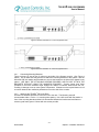
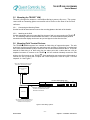

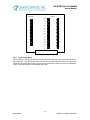
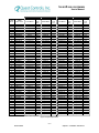

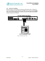


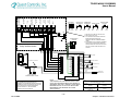
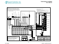
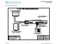

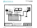
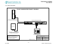
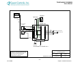
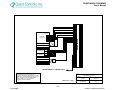

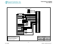
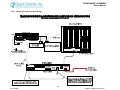


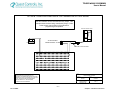


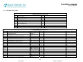
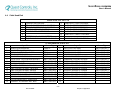
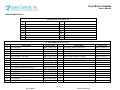
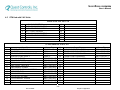


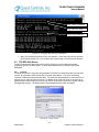

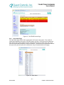
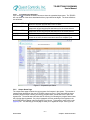
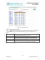
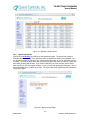

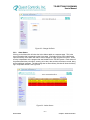


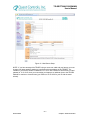


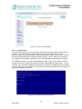

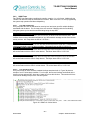


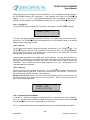
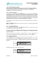
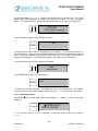

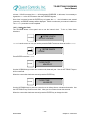

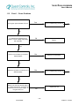
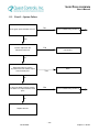
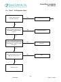

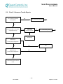
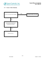


![[APPLICATION FUNCT.] (FUn-) menu](http://vs1.manualzilla.com/store/data/005824711_1-335fb64f289c00db4078a7c61d67b3e9-150x150.png)