1
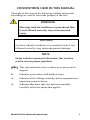
Manual of Operation and Instruction Model 3411-B Advanced Control Unit Troxler Electronic Laboratories, Inc. 3008 E. Cornwallis Road • P.O. Box 12057 Research Triangle Park, NC 27709 U.S.A. Phone: 1.877.TROXLER Outside the U.S.A.: +1.919.549.8661 Fax: +1.919.549.0761 www.troxlerlabs.com Troxler products are protected by U.S. and foreign patents. Copyright 2005 - 2011 Troxler Electronic Laboratories, Inc. All Rights Reserved No part of this manual may be reproduced or transmitted in any form or by any means, electronic or mechanical, including photocopying, recording, or information storage and retrieval systems, for any purpose without the express written permission of Troxler Electronic Laboratories, Inc. PN 110247 Edition 3 October 2011 ii TROXLER SERVICE CENTERS Troxler Corporate Headquarters P.O. Box 12057 Research Triangle Park, NC 27709 Phone: 1.877.TROXLER (1.877.876.9537) Outside the U.S.A.: +1.919.549.8661 Fax: +1.919.549.0761 North Carolina Service Center Technical Support 3008 E. Cornwallis Road Phone: 1.877.TROXLER Research Triangle Park, NC 27709 (1.877.876.9537) [email protected] Phone: +1.919.549.8661 Fax: +1.919.549.0761 [email protected] Midwestern Office & Service Florida Office & Service Center Center 2376 Forsyth Road 1430 Brook Drive Orlando, FL 32807 Downers Grove, IL 60515 Phone: +1.407.681.4221 Phone: +1.630.261.9304 Fax: +1.407.681.3188 [email protected] Fax: +1.630.261.9341 [email protected] Southwestern Office & Service Western Office & Service Center Center 11300 Sanders Drive, Suite 7 2016 East Randol Mill Rd., Suite 406 Rancho Cordova, CA 95742 Arlington, TX 76011 Phone: +1.916.631.0234 Phone: +1.817.275.0571 Fax: +1.916.631.0541 [email protected] Fax: +1.817.275.8562 [email protected] Troxler Electronic Technologies Troxler Europe & Service Center (Zhangjiagang) Troxler Electronics GmbH 1F, Bldg G, No. 1 Guotai North Road Gilchinger Strasse 33 D.82239 ZJG, China, 215600 Alling nr. Munich, Germany Phone: 0086.512.56793702 Phone: ++ 49.8141.71063 Fax: 0086.512.56793701 Fax: ++49.8141.80731 [email protected] [email protected] To locate an independent, Troxler-authorized service partner near you, call 1.877.TROXLER (1.877.876.9537). Model 3411-B Advanced Control Unit iii HOW TO USE THIS MANUAL Congratulations on the purchase of the Troxler Model 3411-B Advanced Control Unit (ACU). The ACU enables the owner of a Troxler Model 3411-B Surface Moisture-Density Gauge to enjoy all the features and functions of our Model 3430 gauge for less than the cost of a new gauge. The Model 3411-B Advanced Control Unit Manual of Operation and Instruction contains information on installing the ACU, and on safely using the Model 3411-B gauge after the ACU has been installed. Also included in this manual are safety warnings, gauge setup, troubleshooting, and general maintenance information. iv CONVENTIONS USED IN THIS MANUAL Throughout this manual the following symbols and special formatting are used to reveal the purpose of the text. WARNING Warnings indicate conditions or procedures that, if not followed correctly, may cause personal injury. CAUTION Cautions indicate conditions or procedures that, if not followed correctly, may cause equipment damage. NOTE Notes indicate important information that must be read to ensure proper operation. 〈KEY〉 This style indicates a key or character to press on the keypad. 1. ♦ Indicates a procedure with multiple steps. Indicates a list of things needed (such as equipment) or important points to know. Indicates that more than one option is available. Carefully select the option that applies. Model 3411-B Advanced Control Unit v TABLE OF CONTENTS CHAPTER 1 : INTRODUCTION Introduction .......................................................................................................... 1–2 Installing the ACU ............................................................................................... 1–3 Entering the Calibration Constants .............................................................. 1–4 CHAPTER 2 : OPERATING THE GAUGE The Keypad ............................................................................................................ 2–2 Turning the Gauge On ...................................................................................... 2–4 Gauge Parameter Setup ................................................................................... 2–5 Taking the Standard Count ............................................................................. 2–8 Site Preparation/Gauge Positioning .......................................................... 2–10 Taking a Measurement – Soil Mode ......................................................... 2–14 Taking a Measurement – Asphalt Mode ................................................. 2–18 CHAPTER 3 : ADVANCED GAUGE OPERATION Offsets ..................................................................................................................... 3–2 Special Calibrations ............................................................................................ 3–8 Thin Layer Measurements ............................................................................. 3–12 CHAPTER 4 : SPECIAL FUNCTIONS Recall........................................................................................................................ 4–2 Offset ....................................................................................................................... 4–2 Stat Test .................................................................................................................. 4–2 Drift Test ................................................................................................................. 4–5 Special Calibration .............................................................................................. 4–7 Specific Gravity .................................................................................................... 4–7 Voidless Density .................................................................................................. 4–8 Set Units ................................................................................................................. 4–8 Calibration Constants ........................................................................................ 4–9 Memory Reset ...................................................................................................... 4–9 Test Reading ....................................................................................................... 4–10 15-Second Inhibit ............................................................................................. 4–11 vi APPENDIX A : SPECIFICATIONS Electrical Specifications .....................................................................................A-2 APPENDIX B : PERIODIC MAINTENANCE & SERVICE Troubleshooting................................................................................................... B-2 Battery Charging .................................................................................................. B-9 Replacement Parts ........................................................................................... B-10 Returning the Gauge for Service ................................................................ B-12 INDEX WARRANTY Model 3411-B Advanced Control Unit vii LIST OF FIGURES Figure 2–1. Model 3411-B ACU Keypad .................................................... 2–2 Figure 2–2. Drill Rod Positioning ................................................................2–11 Figure 2–3. Marking the Test Area .............................................................2–12 Figure 2–4. Voids Illustration........................................................................2–17 Figure B–1. Model 3411-B ACU Assembly .............................................. B-11 LIST OF TABLES Table 2–1. Model 3411-B ACU Keypad Functions ................................. 2–3 Table 3–1. K Values for Thin Lift Overlays ...............................................3–14 viii Chapter 1: Introduction This chapter covers the following topics and tasks: An introduction to the 3411-B ACU Installing the ACU Entering calibration constants Model 3411-B Advanced Control Unit 1–1 Introduction The Model 3411-B Advanced Control Unit (ACU) enables the owner of a Troxler Model 3411-B Surface Moisture-Density Gauge to enjoy all the features and functions of our Model 3430 gauge for less than the cost of a new gauge. The ACU is a direct replacement for the 3411-B’s original scaler and adds a number of improvements over the original: ♦ ♦ ♦ ♦ ♦ ♦ 1–2 The ACU features a 2-line by 16-character alphanumeric liquid crystal display (LCD), providing more information to the gauge operator. The display features a backlight for greater visibility in low-light conditions. All gauge functions are controlled from a 10-key sealedmembrane keypad and software menus, for increased reliability over the original mechanical switches. The ACU provides built-in statistical stability (stat) test and drift test functions, eliminating the need for you to manually calculate the standard deviation and average of multiple readings while performing these tests. The ACU features moisture, density, and trench offsets, which enable you to adjust the gauge for use on materials not covered by the factory calibration. The ACU does not require a new calibration after its installation into a 3411-B gauge. The user simply enters the calibration constants from the gauge’s last factory calibration sheet, and the gauge is ready for use. The ACU requires use of the AC charger (part number 110403) and DC charger (part number 104156). Be sure to use the proper charger once the ACU is installed on the gauge. Installing the ACU CAUTION To prevent possible damage to electronic components from electrostatic discharge (ESD), wear a grounded wrist strap during installation. To install the ACU in a 3411-B gauge: 1. Loosen the four captive screws located in the corners of the 3411-B gauge’s scaler (front panel). 2. Gently pull the scaler out of the gauge, using care not to damage the ribbon cable connecting the scaler electronics to the gauge. 3. Disconnect the ribbon cable from the scaler and set the scaler aside. 4. Connect the ribbon cable to connector J8 on the Model 3411-B ACU. J8 is located on the circuit board labeled 110238 REV. X (TOP), where X is the current revision of the board. Ensure that the polarizing key on the ribbon cable connector is aligned with the slot in connector J8. 5. Place the ACU into the gauge, using care not to pinch the ribbon cable. Secure the ACU using the four captive screws located in the corners of the ACU. 6. Enter the gauge calibration constants as described in the following section. NOTE After installing the ACU, take a standard count as described on page 2–8 before using the gauge to take measurements. A standard count should also be performed any time the ACU is disconnected from the gauge. Model 3411-B Advanced Control Unit 1–3 Entering the Calibration Constants The calibration constants are a set of mathematical constants used by the gauge when calculating a test result. These constants are developed when the gauge is calibrated, and are unique to a particular gauge. The constants for a gauge are listed on the most recent calibration sheet provided with the gauge. NOTE Each gauge contains a unique set of calibration constants. The constants used in one gauge will not work in another gauge! The constants for your gauge are developed when the gauge is calibrated and are reflected on the most recent calibration sheet. NOTE If the calibration sheet lists B and F values, instead of B*1000 and F*1000 values, then the calibration is in English, rather than metric, units. Therefore, the B and F values must be converted to metric values and multiplied by 1000 before they are entered into the gauge. A more direct method is to multiply the B and F values by 62.4298, then enter the resulting products into the gauge. After installing the ACU as described on page 1–3, the calibration constants must be entered as follows. The Calibration Constants feature is one of the gauge’s Special functions. To access the Special functions, press 〈SPECIAL〉. To access the Calibration Constants feature, press the down arrow key eight times and press 〈START/ENTER〉. 1–4 This feature requires the input of the access code given to you by your Troxler representative. Using the up and down arrow keys to select the correct number for the flashing digit, enter the access code. To accept the flashing value and select the next digit, press 〈START/ENTER〉. The gauge then prompts for the input of the E value. NOTE If the value is negative, enter a minus sign (–) by pressing the down arrow key prior to entering the first digit. Leading zeros must be entered (for example: 0.012345). To change the value of the flashing digit for the E value, use the up and down arrows. To accept the flashing value and select the next digit, press 〈START/ENTER〉. Enter the remaining constants for each depth. Model 3411-B Advanced Control Unit 1–5 NOTES 1–6 Chapter 2: Operating the Gauge This chapter covers the following topics and tasks: Basic operation and keypad Setting up gauge parameters Preparing the test site Taking standard counts and measurements Model 3411-B Advanced Control Unit 2–1 The Keypad The keypad (see Figure 2–1) of the Model 3411-B Advanced Control Unit (ACU) consists of ten keys — an eight-function keypad and the 〈ON/YES〉 and 〈OFF/NO〉 keys – and a backlight switch. The gauge is equipped with a beeper to verify keystrokes. If a beep is not heard when a key is pressed, the keystroke was not recognized and should be repeated. The 〈ON/YES 〉 and 〈OFF/NO 〉 keys are used for responses to specific questions displayed on the screen and to turn the gauge on and off. The up and down arrows allow you to scroll through various function lists displayed by the gauge. The backlight switch toggles the display backlight on and off. BATTERY CHARGER CONNECTOR BACKLIGHT SWITCH 3411B Advanced Control Unit ON YES MA PR OFF NO TIME STD START ENTER Figure 2–1. Model 3411-B ACU Keypad 2–2 Table 2–1 provides a more detailed description of the individual keys and the location in the manual where each function is described. Table 2–1. Model 3411-B ACU Keypad Functions KEYS DESCRIPTION ON YES Turns on the gauge and answers Yes to prompts. OFF NO Turns gauge off and answers No to prompts ↑ Scrolls the display up. ↓ Scrolls the display down. MA PR PAGE 2–4 Allows entering or enabling of a Proctor or Marshall value. 2–7 TIME Allows you to change the count time. 2–6 STD Use to access the Standard Count mode. 2–8 Allows entry of the source rod depth. 2–6 DEPTH SPECIAL START ENTER Provides access to the Special functions. 2–5, 3–3, 3– 4, 3–6, 4–1 Starts a measurement or completes answer entry. Model 3411-B Advanced Control Unit 2–3 Turning the Gauge On The gauge uses rechargeable NiCad batteries (included) as a power source. When first turned on, the ACU displays test characters before proceeding to the self-test. NOTE If the gauge turns off immediately after it is turned on, the battery charge may be low or the gauge may be wet inside. Refer to Appendix B of this manual for information on battery charging, and to the Model 3400-B Manual of Operation and Instruction for information on inspecting and replacing gaskets. To turn the gauge on, press 〈ON/YES〉. The gauge performs a test of its liquid crystal display (LCD): After the 300-second self-test, the gauge enters the Ready mode. In this state any of the gauge functions may be accessed. The Ready mode display is: The first line of the display indicates the current count time. The second line of the display indicates the source rod depth that has been selected. NOTE The gauge will automatically turn off after five hours if no keys are pressed. 2–4 Gauge Parameter Setup After unpacking the gauge and turning it on, several parameters can be initialized. These parameters do not usually require changing and include the measurement units and count time. Setting Measurement Units The ACU allows measurement results to be displayed in either metric or US units. To set the measurement units, first access the Special function menu by pressing 〈SPECIAL〉. The gauge displays: ↑ ↓ Press the down arrow seven times to display: ↑ ↓ To select Set Units, press 〈START/ENTER〉. ↑ ↓ Use the up and down arrows to scroll through the available units. When the desired units are displayed, press 〈START/ENTER〉. Model 3411-B Advanced Control Unit 2–5 Setting the Count Time The count time defines how long the gauge measures. Longer count times produce better measurement precision. Troxler recommends a count time of one minute for most sample measurements. To change the count time, press 〈TIME〉 to display: ↑ ↓ Use the up and down arrows to scroll through the available count times. When the desired count time is displayed, press 〈START/ENTER〉. Setting the Depth To change the depth of measurement, press 〈DEPTH〉. ↑ ↓ Use the up and down arrows to scroll through the available measurement depths. When the desired depth is displayed, press 〈ON/YES〉 to select the displayed depth and return to the Ready mode. This is the depth at which the source rod will be positioned for the current measurement and should be changed if the desired measurement depth changes. 2–6 Selecting the Mode (Marshall/Proctor) The gauge may be used on typical construction materials (soils, asphalt, concrete, and so on). To select the Soil mode, enter or activate a Proctor value. To select the Asphalt mode, enter or activate a Marshall value. Only one Marshall and one Proctor can be stored in the gauge at one time. NOTE To measure concrete, either the Asphalt or Soil mode can be used. If the target density used is a Dry Density (Proctor), use Soil mode. If the target is a Wet Density value, use Asphalt mode. To enter or activate a Marshall or Proctor value, press 〈MA/PR〉. The display will be one of the following: ↑↓ ↑↓ To switch from a Marshall value to a Proctor value, or vice versa, use the arrow keys. To activate the displayed value, press 〈OFF/NO〉. To change the displayed value, press 〈ON/YES〉. The first digit of the value will flash. Use the arrow keys to scroll through the possible entries (0 – 9 and •). When the correct value for the current digit is displayed, press 〈START/ENTER〉. The gauge will proceed to the next digit to the right. When the value entry is complete, the gauge activates the value and returns to the Ready mode. Model 3411-B Advanced Control Unit 2–7 Taking the Standard Count The gauge uses a cesium-137 and an americium-241:beryllium source for taking measurements. These radioactive sources undergo a natural decay process, resulting in a gradual loss in the intensity of their radiation. The time required for the source strength to diminish by 50% is referred to as the half-life. To compensate for the source decay and to check proper operation of the gauge, a daily reference standard count should be performed. To ensure the highest accuracy possible with the gauge, it is important to take a daily standard count. NOTE A standard count should be performed after the ACU is installed before using the gauge to take measurements. A standard count should also be performed any time the ACU is disconnected from the gauge. The gauge is equipped with a reference standard block for taking the standard count. Place the reference standard block on a dry, flat surface at least three meters (10 ft) from any large vertical surface and at least ten meters (33 ft) from any other radioactive source. The surface should be asphalt, concrete or soil at least ten centimeters (4 in) thick and with a density of at least 100 pcf. Place the gauge on the reference standard block. The right side of the gauge, farthest from the handle, should be against the metal butt plate. To begin the standard count procedure, press 〈STD〉. 2–8 To take a new standard count, press 〈ON/YES〉. Ensure that the gauge is positioned as described above. To initiate the standard count, press 〈START/ENTER〉. After the count is complete, the display will be: Troxler recommends that you keep a daily log of the moisture and density standard counts (see the Model 3400-B Manual of Operation and Instruction originally supplied with the Model 3411-B gauge). To verify gauge stability, compare the daily standard count to a reliable reference as follows: ♦ ♦ During the first four days of operation of a new or recalibrated gauge, compare the daily standard count to the factory calibrated values. After the first four days of operation (or after taking four standard counts), compare the daily standard count to the average of the last four counts. Acceptable standard count limits are: ±1% change each day for DS (density standard) and ±2% change each day for MS (moisture standard). After recording the standard counts, return to the Ready mode by pressing 〈ON/YES〉. Model 3411-B Advanced Control Unit 2–9 Site Preparation/Gauge Positioning Preparation of the test site surface is critical to gauge performance. This section provides site preparation procedures for both soils and base courses and asphalt surfaces. To ensure the most accurate gauge readings, the appropriate preparation procedure should be followed. Soil and Base Course Preparation 1. Since soil surface conditions are critical to accurate measurements, locate a level site free from any large holes, cracks, or debris. 2. Smooth the surface by moving the scraper plate in a back and forth motion. Filler such as fine sand may be used to decrease the surface voids. NOTE Use only enough filler to fill the voids. Too much filler will cause an error in the measurement. 3. For direct transmission measurements, put the drill rod through the extraction tool and then through one of the guides on the plate (see Figure 2–2). 4. Wearing a radiation badge and safety glasses (or other locally approved safety devices), step on the plate and hammer the drill rod at least 50 millimeters (2 in) deeper than the desired test depth. The drill rod increments include the additional depth. 2–10 5. Remove the drill rod by pulling straight up and twisting the extraction tool. Do not loosen the drill rod by tapping from side to side with a hammer. This will distort the hole or cause loose material to fall into the hole. 6. To ensure accurate placement of the gauge, before removing the scraper plate mark the test area using the drill rod as shown in Figure 2–3. 7. Carefully pick up the scraper plate and place the gauge on the surface prepared by the plate. Insert the source rod into the hole made by the drill rod. Use care when inserting the source rod, trying not to disturb the soil around the hole. Figure 2–2. Drill Rod Positioning Model 3411-B Advanced Control Unit 2–11 8. Lower the source rod into the hole. Release the trigger and lock the source rod into the correct position. A click should be heard when the source rod is locked into position. 9. Gently slide the gauge toward the keypad so the source rod makes contact with the wall of the hole. EDGE MARKS MARK FOR SCRAPER PLATE CENTER SCRAPER PLATE METHOD 1 MARK FOR DRILL ROD CENTER SCRAPER PLATE METHOD 2 Figure 2–3. Marking the Test Area 2–12 Asphalt Surface Preparation It is possible, but usually not necessary, to take direct transmission readings on asphalt. Drilling a hole in asphalt can be difficult, and may require the use of a drill (rather than the drill rod) if the asphalt has cooled and hardened. Under normal conditions, a backscatter reading provides a reliable measurement of asphalt density. 1. Find a smooth, level location on the asphalt. You may want to fill the voids on open mixes with sand or cement. Take care to leave the asphalt exposed. The gauge base must rest on the asphalt, not the fill material! 2. Ensure that the gauge does not “rock.” It must remain steady. If rocking occurs, find a more suitable test site. If taking a measurement around a core, the gauge may be moved a few inches away from the hole to level the gauge. Model 3411-B Advanced Control Unit 2–13 Taking a Measurement – Soil Mode The Soil mode is automatically selected when a Proctor value is enabled (see page 2–7). CAUTION When not taking measurements, always keep the source rod in the SAFE position. For added operator safety, the source rod on the gauge automatically retracts to the SAFE position when the gauge is lifted by the handle. If you do not hear a click when the source rod is raised to the SAFE position, look at the bottom of the gauge to verify that the sliding block is completely closed. If the gauge base opening is not completely closed by the sliding block, the sliding block may require cleaning. Refer to the Model 3400-B Series Manual of Operation and Instruction for cleaning instructions. CAUTION Do not store or transport the gauge unless the sliding block is completely closed. Increased radiation levels may violate transportation regulations and cause excessive personnel exposure. 2–14 Place the gauge over the test site. Release the gauge handle and push it down until it is in the correct position. Ensure that the pin engages the notch in the index rod. Press 〈START/ENTER〉. After the count time has elapsed, the gauge displays the measurement results in a series of six screens, as follows. Use the up and down arrows to scroll through the various screens. ↑ ↓ Model 3411-B Advanced Control Unit 2–15 where: M Count = Moisture counts as read by the gauge D Count = Density counts as read by the gauge WD = Wet density in kg/m3 or pcf DD = Dry density in kg/m3 or pcf %PR = Percent Proctor (This value is valid only if an appropriate target has been entered for the material being tested.) MOIST = Moisture value in kg/m3 or pcf % MOIST = Percent moisture Air Void = See description below Void Ratio = See description below MOIST CR = Moisture count ratio DENS. CR = Density count ratio Press 〈ON/YES〉 to return to the Ready mode. 2–16 Figure 2–4 illustrates the terms void ratio and % air voids. The void ratio is the ratio of the volume occupied by air and water in the soil to the volume occupied by solid particles. The term % air voids refers to the volume of air voids only as a percentage of the total volume. The following formulas are used to calculate the % air voids and void ratio values. % AIR VOIDS = 100 (1 – (Vs/Vt) – (Vw/Vt)) where: Vs = Volume of Soil Vt = Total Volume Vw = Volume of Water or, % AIR VOIDS = 100 (1 – (DD / SG(Dw)) – (M / (Dw))) where: Dw = Density of Water SG = Specific Gravity of Soil Particles DD = Dry Density M = Moisture VOID RATIO = Volume of Voids / Volume of Soil = ( SG(Dw) – DD ) / DD Figure 2–4. Voids Illustration Model 3411-B Advanced Control Unit 2–17 Taking a Measurement – Asphalt Mode The Asphalt mode is automatically selected when a Marshall value is enabled (see page 2–7). CAUTION When not taking measurements, always keep the source rod in the SAFE position. For added operator safety, the source rod on the gauge automatically retracts to the SAFE position when the gauge is lifted by the handle If you do not hear a click when the source rod is raised to the SAFE position, look at the bottom of the gauge to verify that the sliding block is completely closed. If the gauge base opening is not completely closed by the sliding block, the sliding block may require cleaning. Refer to the Model 3400-B Manual of Operation and Instruction for cleaning instructions. CAUTION Do not store or transport the gauge unless the sliding block is completely closed. Increased radiation levels may violate transportation regulations and cause excessive personnel exposure. Place the gauge over the test site. Release the gauge handle and push it into the backscatter position. Set the depth to Backscatter. Ensure that the pin engages the notch in the index rod. Gently tap the handle down to ensure proper source rod seating. 2–18 Press 〈START/ENTER〉. After the count time has elapsed, the gauge displays the measurement results in a series of six screens, as follows. Use the up and down arrows to scroll through the various screens. ↑ ↓ Model 3411-B Advanced Control Unit 2–19 where: WD = Wet density in kg/m3 or pcf % MA = Percent Marshall (This value is valid only if an appropriate target has been entered for the material being tested.) DD = Dry density in kg/m3 or pcf MOIST = Moisture value in kg/m3 or pcf % MOIST = Percent moisture % VOIDS = 100 (1 – WD/VOIDLESS) 100 – % MA = Value given by subtracting the percent Marshall value from 100 MOIST CR = Moisture count ratio DENS. CR = Density count ratio M Count = Moisture counts as read by the gauge D Count = Density counts as read by the gauge Press 〈ON/YES〉 to return to the Ready mode. 2–20 Chapter 3: Advanced Gauge Operation This chapter covers the following topics and tasks: Working with offsets Performing special calibrations Taking thin layer measurements Model 3411-B Advanced Control Unit 3–1 Offsets The Model 3411-B gauge is factory-calibrated for soils, asphalt, and concrete with an approximate density range of 1100 to 2700 kg/m3 (70 to 170 pcf). With an offset, you can adjust the gauge readings to correlate to traditional laboratory methods, such as core samples. The Model 3411-B ACU provides three offsets: density, moisture, and trench. NOTE When an offset has been enabled, all future readings will automatically be adjusted with the offset factor regardless of the test site. It is very important that you disable the offset function prior to taking readings on materials that do not require an offset. Offsets are disabled if the gauge is turned off for more than 10 seconds. Density offsets are common when the material being measured is outside the range of 70 to 170 pcf (1121 to 2723 kg/m3) or if the material composition varies from average soil/asphalt on which the factory calibration is based. Moisture offsets are required for accurate measurements if the material to be measured contains elements that can cause the gauge to yield erroneous results. A negative offset is required if the material to be measured is high in hydrogenous components such as cement, gypsum, coal, or lime. A positive offset is required if the material is high in neutron-absorbing material such as boron or cadmium. The gauge requires an offset if measurements are to be taken inside a trench or close to vertical structures. Vertical structures can scatter neutrons and gamma photons back to the gauge, increasing the possibility of moisture or density errors due to high counts. 3–2 Density Offset To access the Special functions, press 〈SPECIAL〉. Press the down arrow key once to access the Offset function. Press 〈START/ENTER〉 to display: ↑ ↓ Press 〈START/ENTER〉. To enable the Density Offset function, press 〈ON/YES〉. ↑ ↓ Input the difference between the gauge wet density readings and actual wet density readings. Press the down arrow first to input a minus sign (for a negative offset). To scroll through the numerals, press up and down arrows. To select the next digit and/or exit, press 〈START/ENTER〉. The display will be: Model 3411-B Advanced Control Unit 3–3 Moisture Offset Some soils contain hydrogen sources other than water and may contain neutron absorbers. Because the gauge measures moisture by determining the hydrogen content of the material and relating this to the water content, these types of material could cause gauge readings that differ from the true moisture. If measuring such materials, use a moisture offset to adjust the readings. The offset factor (k) is determined by comparing the moisture content of a laboratory sample with the moisture content determined by a gauge reading. To determine the offset factor, use the following procedure: 1. Take a gauge reading at the site. Record the reading (%MGAUGE). 2. Remove a sample from the measurement site, then use laboratory methods (for example, oven dry) to determine the moisture content of the sample (%MLAB). Multiple samples and measurements may be taken. Calculate the average moisture of the samples. This average value should be used for the offset factor calculation. 3. Calculate the offset factor (k). k= %MLAB – %MGAUGE 100 + %MGAUGE × 1000 NOTE If the k value is negative, enter a minus sign (–) by pressing the down arrow before entering the first digit. 3–4 To access the Special functions, press 〈SPECIAL〉. Press the down arrow key once to access the Offset function. Press 〈START/ENTER〉 to display: ↑ ↓ To enter a moisture offset, press the down arrow once and press 〈START/ENTER〉. To enable the Moisture Offset function, press 〈ON/YES〉. ↑ ↓ The first digit will flash. To input a minus (–) sign (for a negative offset), press the down arrow first! To scroll through the possible values for each digit, press the arrow key. To select the next digit, press 〈START/ENTER〉. When all digits are entered, the gauge will enable the offset. The display will be: Model 3411-B Advanced Control Unit 3–5 Trench Offsets If the gauge is to be used for moisture or density measurements in a trench or within two feet (0.6 m) of a large vertical structure, a trench offset may be required. If used, the trench offset adjusts all moisture measurements. Only the density measurements from backscatter through four inches (10 cm) will be corrected by the gauge. To perform a trench offset: 1. Take the daily standard count (outside the trench) as usual and record the density count (DS) and moisture count (MS) values. 2. Place the gauge on the reference standard block in the trench the same distance from the wall as the anticipated readings. Do not take another standard count. 3. Set the count time to four minutes. 4. With the source rod in the SAFE (standard count) position, take a four-minute count. To start the count, press the 〈START/ENTER〉 key (not the 〈STD〉 key) 5. Record the trench density count (DCTrench) and moisture count (MCTrench.). 6. Subtract the daily standard count values from the trench count values: Dens Cnst = (DCTrench) – DS Mois Cnst = (MCTrench) – MS To enable a trench offset, press 〈SPECIAL〉 to access the Special functions, then press the down arrow key once to access the Offset function. Press 〈START/ENTER〉 to display: ↑ ↓ 3–6 To enter a trench offset, press the down arrow twice and press 〈START/ENTER〉. To enable the Trench Offset function, press 〈ON/YES〉. ↑ ↓ The gauge requests the Mois Cnst and Dens Cnst values determined earlier. The procedure for entering the values is the same as for moisture and density offsets, ignoring the ± sign on the display. When the values are complete, the gauge enables the offset and displays: Model 3411-B Advanced Control Unit 3–7 Special Calibrations Troxler gauges are calibrated to “average soil.” Average soil is defined as material consisting of 50% limestone (calcareous) and 50% granite (siliceous). This factory calibration provides accurate results for the majority of materials encountered in the field. However, there are situations when varying material compositions could affect the gauge accuracy. In these special cases the gauge B value can be recalculated either by the gauge or by considering the mass attenuation (µ/ρ) of the material. If the chemical composition of the soil is known, Troxler can provide a procedure for recalculating the B value for manual entry (see page 3–9) to accurately measure the soil density. This calculation requires in-depth knowledge of the gauge geometry and the detected energy spectrum of the Cs-137 source. The Special Calibration function allows the gauge to be recalibrated for material densities and compositions other than those covered by the factory calibration. The true density of a sample of the material must be obtained prior to calculating a special calibration. This density may be obtained from a laboratory sample. To access the Special functions, press 〈SPECIAL〉. To access the Special Calibration function, press the down arrow four times. Press 〈START/ENTER〉 to display: 3–8 To recalibrate the gauge for the densities outside the factory calibration range, press 〈ON/YES〉. To disable the Special Calibration feature, press 〈OFF/NO〉 at the above display and 〈ON/YES〉 at the disable inquiry. After disabling this feature, the gauge will return to the Ready mode. To enter a known B value obtained with the procedure available from Troxler, press 〈ON/YES〉. To have the gauge calculate the recalibration, press 〈OFF/NO〉. If entering a new known B value, see the following explanation. For gauge-calculated special calibration, see page 3–10. Entering a New B Value ↑ ↓ To change the value of the flashing digit for the measurement depth, use the up and down arrows. To accept the flashing value and select the next digit, press 〈START/ENTER〉. ↑ ↓ The gauge displays the current B value. To change the value of the flashing digit, use the up and down arrows. To accept the flashing digit and select the next digit, press 〈START/ENTER〉. Model 3411-B Advanced Control Unit 3–9 Upon entry completion, the gauge will indicate that the special calibration is enabled and return to the Ready mode. Note that when the gauge is turned off the Special Calibration is disabled. Gauge-Calculated Calibration The true density of the sample must be determined, and a gauge reading (calibration count) must be performed on the material in order to calculate and enable a special calibration. NOTE When using destructive methods such as drilling cores or sample removal for true density measurement, take gauge readings before removing samples. To select the depth and/or exit, press 〈START/ENTER〉. ↑ ↓ To scroll through the numerals for the depth of the measurement, press the up and down keys. To select the next field and/or exit, press 〈START/ENTER〉. If calibration counts have not been taken, the gauge will take four one-minute counts. The gauge provides you with a partial calibration feature. A partial calibration allows you to enter the “true” density after taking the gauge reading (calibration counts), which is helpful to those performing destructive material testing. If you have previously taken the calibration counts, the gauge asks if these counts should be used in calibrating the gauge. 3–10 To use the previous counts, press 〈ON/YES〉. The gauge will then request the density. To take new counts, press 〈OFF/NO〉. Place the gauge on the test material. To begin taking the four one-minute counts, press 〈START/ENTER〉. After each count is complete, initiate the next count by pressing 〈START/ENTER〉. To create a partial calibration and return to the Ready mode, press 〈OFF/NO〉. To complete the special calibration by entering the density, press 〈ON/YES〉. ↑ ↓ To change the value of a digit, press the up and down arrows. To select the next digit, press 〈START/ENTER〉. After the density value is entered, the special calibration routine readjusts the gauge for the new material and indicates that the special calibration is enabled. The special calibration is only valid for the depth selected during the special calibration. Model 3411-B Advanced Control Unit 3–11 Thin Layer Measurements Conventional backscatter gauges measure density to depths of approximately 4 inches. To perform readings on layers of asphalt with thickness of 3.33 inches or less, use the following method (formula): DT = WD – DB × K 1–K where: DT = Overlay wet density WD = Density read by gauge DB = Bottom layer wet density K = Effect of top layer thickness on the gauge To use the above method of overlay measurement, follow the procedure below: 1. Determine the density of the bottom layer (underlying material) (DB). 2. Apply the thin lift overlay. 3. Determine the thickness of the overlay and select the corresponding (k) value from Table 3–1 on page 3–14. 4. Measure the thin lift overlay density with the gauge in backscatter position (WD). 5. Enter all values into the above equation and calculate the overlay density (DT). 3–12 Example Given the following values: Bottom Density (DB) = 135 pcf (2162 kg/m3) Overlay Thickness = 1.2 inches (30 mm) K (from Table 4-1) = 0.38235 Density read by gauge (WD) = 142.0 pcf (2275 kg/m3) DT = 142.0 – (135 × 0.38235) 1 – 0.38235 DT = 146.3 pcf or, DT = 2275 – (2162 × 0.38235) 1 – 0.38235 DT = 2345 kg/m3 NOTE The majority of the backscattered gamma rays reaching the detectors are the result of interactions in the top 3.3 inches (84 mm) of the overlay. In applications where the overlay thickness is greater than 3.3 inches (84 mm), use (0) for the k value or use the actual gauge readings (WD). Model 3411-B Advanced Control Unit 3–13 Table 3–1. K Values for Thin Lift Overlays Thickness (mm) K 55 0.13459 56 0.12880 57 0.12078 58 0.11275 0.40138 59 0.10781 30 0.38235 60 0.10285 31 0.36475 61 0.09790 32 0.35889 62 0.09104 33 0.34716 63 0.08418 34 0.33631 64 0.07995 35 0.32547 65 0.07572 36 0.31462 66 0.07149 37 0.29958 67 0.06562 38 0.28454 68 0.05976 39 0.27527 69 0.05615 40 0.26600 70 0.05253 41 0.25673 71 0.04892 42 0.24387 72 0.04390 43 0.23102 73 0.03889 44 0.22310 74 0.03580 45 0.21517 75 0.03271 46 0.20725 76 0.02962 47 0.19626 77 0.02676 48 0.18527 78 0.02391 49 0.17850 79 0.02105 50 0.17172 80 0.01709 51 0.16495 81 0.01313 52 0.15556 82 0.01069 53 0.14617 83 0.00825 54 0.14038 84 0.00581 Thickness (inches) Thickness (mm) K 1.0 25 0.46159 26 0.44787 27 0.43414 28 0.42042 29 1.1 1.2 1.3 1.4 1.5 1.6 1.7 1.8 1.9 2.0 2.1 3–14 Thickness (inches) 2.2 2.3 2.4 2.5 2.6 2.7 2.8 2.9 3.0 3.1 3.2 3.3 Chapter 4: Special Functions This section covers the following topics and tasks: Special gauge functions Stat and drift tests Memory reset Model 3411-B Advanced Control Unit 4–1 Recall The Recall function allows you to view the data from the last reading. Even though the ACU does not store multiple readings, this function displays the latest data. To access the Special functions, press 〈SPECIAL〉. To access the Recall feature, press 〈START/ENTER〉. The gauge displays the data from the last measurement. Scroll through the screens using the up and down arrow keys. Offset For information on offsetting gauge readings, refer to page 3–2. Stat Test The statistical stability test, or stat test, may be performed to validate the normal operation of the gauge. Erratic readings or readings that seem to fluctuate may indicate a problem with the gauge. In the event the readings are suspect, a stat test may be executed. A stat test consists of 20 one-minute counts. After the 20 counts, the gauge calculates the standard deviation. This standard deviation is compared to a theoretical standard deviation value. Ideally this ratio should be one. However, the ACU pre-scales (or divides) the counts by 16, resulting in an ideal ratio of 0.25. The acceptable limits for the ratio are from 0.17 to 0.33. The gauge is considered unstable if the ratio is outside these limits. 4–2 To perform a stat test, place the gauge on the reference standard block in the standard count position (see page 2–8). To access the Special functions, press 〈SPECIAL〉. To access the Stat Test feature, press the down arrow twice and press 〈START/ENTER〉. To begin the twenty counts, press 〈START/ENTER〉. The gauge will display the stat test count progress as shown below. Upon completion of the stat test, the gauge displays the pass/fail status. If the stat test fails, repeat the test twice more. If two out of three stat tests fail, contact Troxler Technical Support. If the stat test passes, the display is: ↑↓ Model 3411-B Advanced Control Unit 4–3 To view the stat test data, use the up and down arrow keys. ↑↓ ↑↓ ↑↓ ↑↓ • • • ↑ ↓ 4–4 Drift Test If the stat test has already been performed (and passed), but gauge readings seem to drift between tests, the drift test can check the long-term drift of the gauge. A drift test consists of 5 four-minute counts taken approximately three to eight hours after completion of a stat test with no movement of the gauge between tests. Pass/fail limits are set using the percent difference between the average of the stat and drift test results. If the percent difference exceeds 0.5% for density or 1% for moisture, the drift test fails. NOTE The gauge should not be turned off between the stat test and drift test. The stat test must be current. In addition, the gauge must not be moved between the stat and drift tests to eliminate possible failure due to positioning changes. With the gauge still in the standard count position (on the reference standard block), press 〈SPECIAL〉. From the Special functions, select the Drift Test feature by pressing the down arrow three times and 〈START/ENTER〉. To begin the five counts, press 〈START/ENTER〉. Model 3411-B Advanced Control Unit 4–5 As with the stat test, the gauge indicates the count progress during the drift test. After the five counts have been completed, the display is: ↑↓ To view the drift test data, use the up and down arrow keys. ↑↓ ↑↓ ↑↓ • • • ↑ ↓ 4–6 Special Calibration For information on performing a special calibration, see Chapter 3. Specific Gravity The specific gravity of a solid is defined as the density of the material divided by the density of water. The Specific Gravity function allows you to input the specific gravity of a material into the gauge. This value (SG) is used in the calculation of % Air Voids and Void Ratio (see Chapter 2). To access the Special functions, press 〈SPECIAL〉. To access the Specific Gravity feature, press the down arrow five times and press 〈START/ENTER〉. ↑ ↓ To change the value of the flashing digit, use the up and down arrows. To accept the flashing value and select the next digit, press 〈START/ENTER〉. If a value is not entered, the default value is 2.70, the “typical” specific gravity for soil. Model 3411-B Advanced Control Unit 4–7 Voidless Density The Voidless Density function allows the input of the theoretical voidless density value of the material being measured. This value is used in the % Voids calculation, typically applicable in asphalt density measurements. To access the Special functions, press 〈SPECIAL〉. To access the Voidless Density feature, press the down arrow six times and press 〈START/ENTER〉. ↑ ↓ To change the value of the flashing digit, use the up and down arrows. To accept the flashing value and select the next digit, press 〈START/ENTER〉. Set Units For information on the Set Units feature, see page 2–5. 4–8 Calibration Constants The Calibration Constants function allows you to change the mathematical constants used for calculating a test result. If the gauge has been repaired or the memory has been lost, the constants must be verified or re-entered. NOTE Each gauge contains a unique set of constants. The constants used in one gauge will not work in another gauge! The constants for your gauge are developed when the gauge is calibrated and are reflected on the most recent calibration sheet. For more information on the Calibration Constants feature, refer to page 1–4. Memory Reset NOTE This function is for authorized service personnel only! CAUTION Memory Reset erases all data stored in the gauge and sets all constants, except calibration constants, to the default values. Model 3411-B Advanced Control Unit 4–9 Test Reading NOTE This function is for authorized service personnel only! 4–10 15-Second Inhibit The 15-Second Inhibit function disables the 15-second count option. When this function is used, the gauge can only conduct one- or four-minute counts. To disable the 15-second count option, first access the Special functions by pressing 〈SPECIAL〉. Use the up or down arrows to display: To access the 15-Second Inhibit function, press 〈START/ENTER〉. This feature requires the input of the access code provided by your Troxler representative. Using the up and down arrow keys to select the correct number for the flashing digit, enter the access code. To accept the flashing value and select the next digit, press 〈START/ENTER〉. If the 15-second count option is currently enabled, the gauge displays: Press 〈ON/YES〉 to disable the 15-second count option. The gauge returns to the Ready mode. Model 3411-B Advanced Control Unit 4–11 If the 15-second count option is currently disabled, the gauge displays: Press 〈ON/YES〉 to enable the 15-second count option. The gauge returns to the Ready mode. 4–12 Appendix A: Specifications This appendix contains the electrical specifications for the Model 3411-B Surface Moisture-Density Gauge when retrofitted with the Model 3411-B Advanced Control Unit (ACU). Note that the measurement, radiological, mechanical, and calibration specifications of the Model 3411-B are not affected by the retrofit, and are therefore unchanged from those shown in the Model 3400-B Manual of Operation and Instruction originally supplied with the gauge. Model 3411-B Advanced Control Unit Appendix A–1 Electrical Specifications Stored Power 40 watt-hours Gauge Charging 12 V dc, 500 mA minimum Keypad 10-key sealed membrane Battery Recharge Time Liquid Crystal Display Power Consumption Appendix A–2 14 to 16 hours 2 line x 16 character alphanumeric < 0.10 watts average Appendix B: Periodic Maintenance & Service This appendix contains information on troubleshooting a Model 3411-B gauge when retrofitted with the Model 3411-B Advanced Control Unit (ACU), as well as information on charging the gauge battery. If a serious problem with the gauge arises, contact Troxler Technical Support for instructions. Model 3411-B Advanced Control Unit Appendix B–1 Troubleshooting Gauge Fails Standard Counts Ensure that the standard count is being performed properly. Ensure that the source rod opening on the gauge bottom is completely closed or covered by the tungsten sliding block. If any opening is visible, the sliding block should be cleaned as described later in the Model 3400-B Manual of Operation and Instruction. If the sliding block still does not close completely, contact the nearest Troxler Technical Support. Compare the current standard counts to the calibration (reference) standard counts, found on the calibration printout from the gauge’s most recent calibration. If they are within 1% for DS and 2% for MS, accept the standard count, then perform and accept four more standard counts. No Density Readings The most likely reason for no density readings is an electronic problem, such as a failure of the detector preamplifier. However, as a precaution, ensure that the tip of the source rod is intact and undamaged (that is, ensure that the source is not missing). Use a radiation survey meter to check the radiation levels on contact with the surface of the gauge base (without extending the source rod). A maximum reading of 10-20 mrem/hr is normal, and indicates the source is present. However, if the maximum reading is less than 1 mrem/hr or if a survey meter is not available, perform a visual inspection of the source rod tip as follows to confirm its integrity: 1. Extend the source rod just far enough to see the source rod tip. The tip should appear flat to slightly rounded and smooth. 2. Stay at least three feet away from the tip of the unshielded source rod and complete the inspection as quickly as possible to minimize exposure (the dose rate Appendix B–2 at three feet from the unshielded source is about 2.7 mrem/hr). If the visual inspection indicates that the source rod tip is broken off (source is missing): 1. Immediately contact your Radiation Safety Officer (RSO). 2. Initiate a search for the source starting at the location where the gauge was last used. 3. Report lost or missing radioactive sources to your state or federal radiation control agency in accordance with applicable regulatory requirements. 4. Contact the Troxler Radiation Safety Department for further advice. Gauge Readings Appear Erratic Ensure that the source rod is properly locked in the desired backscatter or direct transmission position, and is not resting on the test material. Check the inside of the gauge for moisture. To dry the gauge interior, remove the keypad. If necessary, use a hair dryer (on low heat) to circulate warm air for one to three hours. Remove any foreign objects from inside the gauge. Ensure the hardware mounting screws are tight and in place. Check count time – a four-minute count will give the highest precision with a repeatability of ±1 pcf. Erratic density readings may be caused by a dirty sliding block. Clean the sliding block as described in the Model 3400-B Manual of Operation and Instruction. Perform a statistical stability (stat) test (see page 4–2). • If test passes, proceed with measurements. Model 3411-B Advanced Control Unit Appendix B–3 • If test fails, repeat two more times. If test fails two out of three times, contact Troxler Technical Support. NOTE To aid in verifying gauge readings, after a gauge has been calibrated, mark a test area on a concrete floor, sidewalk, or equivalent and measure the density (WD). This measurement can then be used as a reference to verify later gauge readings. Garbage, XXXXXX or ++++++ Displays Check the standard counts in memory. If the standard counts are suspect, perform new standard counts. If counts equal zero for both systems, the high voltage board may need replacing. Contact Troxler Technical Support. Check gauge for water damage. If the gauge is wet, dry the gauge interior with hairdryer (on low heat) for 3 hours. Check the calibration constants. They should match the constants on your most recent calibration data sheet if your calibration sheet is in metric units. (Refer to the note on page 1–5 to determine if your calibration sheet is in metric units and, if not, for instructions on converting B and F values from English to metric units.) If necessary, perform a statistical stability (stat) test (see page 4–2), record the results and contact Troxler Technical Support. Appendix B–4 Gauge Turns Off after it is Turned On The gauge automatically turns off after five hours if no keys are pressed. Try to turn the gauge on again. The gauge may be wet. Do not turn the gauge on until moisture is removed from gauge interior! Component damage may result. If the battery is below 3.0 volts, recharge or replace the batteries. The scaler may be defective. To test, replace the suspect scaler with a good scaler. Short Battery Life after Recharging NiCad batteries may be charged up to 100 full chargedischarge cycles. The batteries may be reaching end of life cycle - replace. Note that all information stored in the gauge except the calibration constants and the chosen language is lost when the batteries are disconnected. Charger/adapter may not be supplying full charge – check the ac outlet and the dc output (12 V dc). Check the output voltage of your charger. The correct output voltage is indicated on the charger unit. Check that you are using the correct charger. Remove any loose screws or foreign objects from the gauge interior that may cause an electrical short to ground. The ac charger may be defective. Check voltage output of charge with a voltmeter, or use the dc charger to charge the batteries. Model 3411-B Advanced Control Unit Appendix B–5 Satisfactory Counts, but Results are in Error Ensure the measurement depth corresponds to the actual source rod depth. Check calibration constants. Check to see if an offset (density, moisture, trench or special) is enabled. Ensure that the standard counts are correct. Ensure that the index rod is seated in bottom of notch. Appendix B–6 Possible Malfunction Indicators CPU Board ♦ ♦ ♦ ♦ ♦ ♦ ♦ ♦ ♦ Display Malfunctions No Keypad Response RAM Test Fails Batteries Do Not Recharge Battery Low Indicator Does Not Function Correctly Display Test Fails Gauge Doesn't Turn "Off" Beeper Stops (or is erratic) Gauge Does Not Turn On When Charger Is Connected Preamp Board ♦ ♦ ♦ ♦ No Moisture or Density Counts Batteries Do Not Recharge Gauge Fails Tube Test Fails Stability or Drift Tests HV Board ♦ ♦ ♦ ♦ No Moisture or Density Counts Moisture or Density Counts are Unstable Batteries Discharge Prematurely Gauge Fails Stability or Drift Tests Model 3411-B Advanced Control Unit Appendix B–7 Error Messages The following error messages are not user-serviceable. Contact Troxler Technical Support for more information. KEY PAD TEST ERROR! GM TUBE TEST ERROR! HELIUM TUBE TEST ERROR! DISPLAY TEST ERROR! Model 3411-B Advanced Control Unit 8 Battery Charging With fully charged batteries, the gauge will remain operational for approximately eight weeks under normal (8-hour day) conditions. If the batteries become discharged, the following message will be displayed on the gauge: When this display appears, there are a few hours remaining before the battery must be recharged. In an emergency, a 30minute recharge with the dc or ac charger gives several hours of use. The ACU requires use of the AC charger (part number 110403) and DC charger (part number 104156). Be sure to use the proper charger once the ACU is installed on the gauge. Although batteries cannot be “overcharged,” rechargeable batteries have a “memory” and repeated unnecessary recharging will shorten the battery life. If possible, run the batteries down before recharging. NOTE Batteries should not be recharged unless the Battery Low! indication is displayed. Model 3411-B Advanced Control Unit Index Replacement Parts Figure B–1 shows the replaceable parts of the Model 3411-B Advanced Control Unit. Match the reference number shown below with the correct part in Figure B–1 on the next page. Ref # Part Number Description Qty. 1 000001.0400 #4 Internal Lock Washer 4 2 000204.1400 4-40 Pan Head Screw, Phillips 4 3 001061.0820 4-40 Hex Spacer, MF 4 4 002516 Jack Cover Assembly 1 5 100528.1000 Captive Thumb Screw, 8-32 4 6 102888 Cable Assembly 1 7 100237 (bottom) Printed Circuit Board Assembly 1 8 110237 (top) Printed Circuit Board Assembly 1 9 110240 Operator Overlay 1 10 110241 Front Panel Assembly 1 11 110245 Charger Jack Assembly 1 12 110248 Cable Assembly 1 13 110254 Cable Assembly, backlight 1 Index Figure B–1. Model 3411-B ACU Assembly Model 3411-B Advanced Control Unit Index Returning the Gauge for Service All shipments to the factory from within the United States must be accompanied by an RGA (Returned Goods Authorization) number, and a description of the instrument and its problem. This information is used by Troxler shipping and service personnel to expedite the repair work. To obtain an RGA number, please call or fax the factory or branch office with your request. Please have the following information available when contacting Troxler for an RGA number: ♦ ♦ ♦ ♦ ♦ ♦ ♦ ♦ ♦ Gauge model and serial number. Part number/serial number (if applicable). Is the gauge still under warranty? Problem or difficulty you are having with the instrument. Shipment method to Troxler and for return shipment. Shipping and billing address (not P.O. Box) – street address and zip code. Telephone number and contact (for questions from Troxler). Will estimate be required before performing any work on the gauge? Payment method: credit card, account number, or purchase order number. All U.S. government agencies (city, county, state and federal) must send purchase order numbers. To prevent order duplication, if an order has been placed by telephone, please write “Confirming Order” on any follow-up written requests. Index INDEX 1 15-Second inhibit ............................................................................................. 4–11 A Asphalt mode ....................................................................................................... 2–7 Automatic shutdown ......................................................................................... 2–4 B Backlight........................................................................................................ 1–2, 2–2 Battery charging.................................................................................................. B–9 C Calibration Constants ................................................................................................................. 1–4, 4–9 Special .................................................................................................................................3–8 Count time ............................................................................................................ 2–6 D Density Offset ...................................................................................................................................3–3 Voidless .............................................................................................................................. 4–8 Depth of measurement .................................................................................... 2–6 Drift test ................................................................................................................. 4–5 E-K Error messages .................................................................................................... B–8 Installation ............................................................................................................. 1–3 Keypad .................................................................................................................... 2–2 Model 3411-B Advanced Control Unit Index M Measurement Asphalt mode ............................................................................................................... 2–18 Depth................................................................................................................................... 2–6 Mode ................................................................................................................................... 2–7 Site preparation ........................................................................................................... 2–10 Soil mode ....................................................................................................................... 2–14 Thin layer ........................................................................................................................ 3–12 Units ..................................................................................................................................... 2–5 Memory reset ....................................................................................................... 4–9 Mode Asphalt ................................................................................................................................ 2–7 Ready................................................................................................................................... 2–4 Soil ........................................................................................................................................ 2–7 Moisture offset..................................................................................................... 3–4 O Offset ....................................................................................................................... 3–2 Density ................................................................................................................................ 3–3 Moisture ............................................................................................................................. 3–4 Trench ................................................................................................................................. 3–6 P Parts, replacement ........................................................................................... B–10 Percent air voids ................................................................................................2–17 R Ready mode .......................................................................................................... 2–4 Recall........................................................................................................................ 4–2 Replacement parts .......................................................................................... B–10 Index S Service Returning gauge .......................................................................................................... B–12 Shutdown, automatic ........................................................................................ 2–4 Soil mode ............................................................................................................... 2–7 Special Calibrations ....................................................................................................................... 3–8 Functions ............................................................................................................................ 4–1 Specific gravity..................................................................................................... 4–7 Specifications ....................................................................................................... A–1 Standard count .................................................................................................... 2–8 Stat test .................................................................................................................. 4–2 T Taking a measurement Asphalt mode ................................................................................................................ 2–18 Soil mode ........................................................................................................................ 2–14 Test Drift ......................................................................................................................................4–5 Stat .......................................................................................................................................4–2 Test reading ........................................................................................................ 4–10 Thin layer measurements .............................................................................. 3–12 Time, count ........................................................................................................... 2–6 Trench offset......................................................................................................... 3–6 Troubleshooting.................................................................................................. B–2 U Units, measurement .......................................................................................... 2–5 V Void ratio ............................................................................................................. 2–17 Voidless density .................................................................................................. 4–8 Model 3411-B Advanced Control Unit Index TROXLER ELECTRONIC LABORATORIES, INC. LIMITED WARRANTY TROXLER ELECTRONIC LABORATORIES, INC., and subsidiary, TROXLER INTERNATIONAL, LTD., hereinafter referred to as “TROXLER,” warrants this instrument, Model _______, Serial Number __________, against defects in material and workmanship for a period of twelve (12) months from date of shipment. For products sold through authorized TROXLER representatives, the date of shipment will be as of the transfer from representative to purchaser. During the applicable warranty period, TROXLER’s obligation under this warranty shall be limited exclusively to the repair at a TROXLER facility at no charge, except for shipping to and from TROXLER’S plant, of any instrument which may prove defective under normal use and which TROXLER’s examination shall disclose to its satisfaction to be thus defective. Normal use is defined for the purpose of this warranty as operation under normal load, usage, and conditions with proper care and maintenance and competent supervision. In no event shall TROXLER be held liable for damages, delays, or losses consequential, incidental, or otherwise attributable to the failure of this instrument. TROXLER’s liability being specifically limited to repair as stated hereinabove. This warranty is automatically initiated except where modified by contractual or other written and signed agreement. THERE ARE NO WARRANTIES WHICH EXTEND BEYOND THE DESCRIPTION ON THE FACE HEREOF, AND THIS WARRANTY IS EXPRESSLY IN LIEU OF ALL OTHER WARRANTIES, EXPRESSED OR IMPLIED, AND TROXLER NEITHER ASSUMES, NOR AUTHORIZES ANYONE TO ASSUME FOR IT ANY OTHER LIABILITY IN CONNECTION WITH THE SALE OF THE INSTRUMENT. THIS WARRANTY SHALL NOT APPLY TO THE INSTRUMENT OR ANY PART THEREOF, WHICH HAS BEEN SUBJECTED TO DAMAGE BY ACCIDENT, NEGLIGENCE, ALTERATION, ABUSE, MISUSE, OR SERVICE NOT AUTHORIZED IN WRITING BY TROXLER. SUCH DAMAGE TO INCLUDE BUT NOT BE LIMITED TO BURNING OF CIRCUIT BOARDS AND HARNESS FROM IMPROPER SOLDERING TECHNIQUES AND DAMAGE TO THE INSTRUMENT DUE TO PURCHASER’S FAILURE TO PERFORM MAINTENANCE AS OUTLINED IN THE AUTHORIZED OPERATOR’S MANUAL. DUE TO THE NATURE OF THEIR USE, MECHANICAL ACCESSORY PARTS AND BATTERIES ARE WARRANTED FOR 90 DAYS ONLY FROM DATE OF SHIPMENT. TROXLER ELECTRONIC LABORATORIES, INC. 3008 E. Cornwallis Road Post Office Box 12057 Research Triangle Park, NC 27709 USA NOTICE TO CONSUMERS Any disclaimer or limitation on the remedies expressed above shall not be effective to the extent prohibited by state or federal law. NOTE: THIS WARRANTY EXCLUDES DAMAGE INCURRED IN SHIPMENT. IF THIS INSTRUMENT IS RECEIVED IN DAMAGED CONDITION, THE CARRIER SHOULD BE CONTACTED IMMEDIATELY. ALL CLAIMS FOR DAMAGE IN TRANSIT SHOULD BE FILED WITH THE CARRIER. IF REQUESTED, TROXLER WILL AID IN FILING OF CLAIMS AND/OR LOCATING PRODUCTS LOST IN TRANSIT.