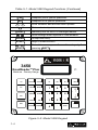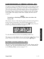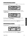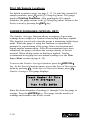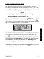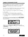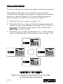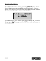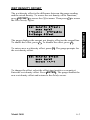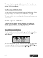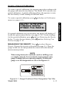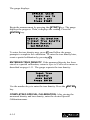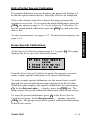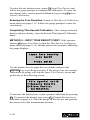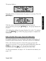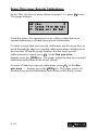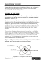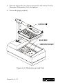
1
Manual of Operation and Instruction
Model 3450
RoadReader™ Plus
Surface Moisture-Density Gauge
Troxler Electronic Laboratories, Inc.
3008 Cornwallis Rd. • P.O. Box 12057
Research Triangle Park, NC 27709
Phone: 1.877.TROXLER
Outside the USA: +1.919.549.8661
Fax: +1.919.549.0761
www.troxlerlabs.com
Troxler gauges are protected by U.S. and foreign patents
Copyright © 1996–2005
Troxler Electronic Laboratories, Inc.
All Rights Reserved
No part of this manual may be reproduced or transmitted in any
form or by any means, electronic or mechanical, including
photocopying, recording, or information storage and retrieval
systems, for any purpose without the express written permission of
Troxler Electronic Laboratories, Inc.
Fantastic is a trademark of Dow Consumer Products, Inc.
Federal Express is a registered trademark of the Federal Express
Corporation.
409 is a trademark of the Clorox Company.
Magnalube-G is a registered trademark of Carleton-Stuart
Corporation.
Microsoft, Excel, Windows, and Word are registered trademarks of
Microsoft Corporation.
RoadReader is a trademark of Troxler Electronic Laboratories, Inc.
WD-40 is a registered trademark of the WD-40 Company.
PN 107837
May 2005
Edition 4.2
ii
TROXLER SERVICE CENTERS
Troxler Corporate Headquarters
3008 Cornwallis Road
P.O. Box 12057
Research Triangle Park, NC 27709
Phone: 1.877.TROXLER (1.877.876.9537)
Outside the U.S.A.: +1.919.549.8661
Fax: +1.919.549.0761
Web: www.troxlerlabs.com
Technical Support
Phone: 1.877.TROXLER (1.877.876.9537)
E-mail: [email protected]
Midwestern Branch Office
1430 Brook Drive
Downers Grove, IL 60515
Fax: 630.261.9341
Florida Service Center
2376 Forsyth Road
Orlando, FL 32807
Fax: 407.681.3188
Western Regional Branch Office
11300 Sanders Drive, Suite 7
Rancho Cordova, CA 95742
Fax: 916.631.0541
Canadian Branch Office
7125 Pacific Circle, Unit 13
Mississauga, Ontario L5T-2A5
Canada
Fax: 905.564.7092
Southwestern Branch Office
2000 East Randol Mill Road
Suite 611
Arlington, TX 76011
Fax: 817.275.8562
Model 3450
Troxler European Subsidiary
Troxler Electronics GmbH
Gilchinger Strasse 33
D.82239 Alling nr. Munich, Germany
Phone: ++49.8141.71063
Fax: ++49.8141.80731
E-mail: [email protected]
iii
HOW TO USE THIS MANUAL
Congratulations on the purchase of the Troxler Model 3450
RoadReader Plus. Troxler continues the proven technology of its
3400 Series surface moisture-density gauges with the Troxler Model
3450 RoadReader Plus.
The Model 3450 Manual of Operation and Instruction contains
information on safely using this gauge. Also included in this manual
are safety warnings, gauge setup, troubleshooting, and general
maintenance.
iv
CONVENTIONS USED IN THIS MANUAL
Throughout this manual, symbols and special formatting are used to
reveal the purpose of the text as follows:
WARNING
Indicates conditions or procedures that, if not followed
correctly, may cause personal injury.
CAUTION
Indicates conditions or procedures that, if not followed
correctly, may cause equipment damage.
NOTE
Indicates important information that must be read to
ensure proper operation.
〈KEY〉
Angle brackets and a different typestyle indicate a
key or character (number or letter) to press on the
gauge keypad. For example, “Press 〈START〉”
means to press the key labeled START.
DISPLAY
A different typestyle is used in text to indicate
information or messages displayed on the gauge.
DISPLAY - Typestyle
and shading used to
simulate the gauge
display
♦
Diamonds indicate a list of things needed (such as
equipment) or things to know.
Check marks indicate the performance of an action.
With lists of check marks, follow the instructions in
the order of the check marks.
Triangles indicate that more than one option is
available. Carefully select the option that applies.
Model 3450
v
NOTES
vi
TABLE OF CONTENTS
CHAPTER 1. INTRODUCTION TO THE MODEL 3450
Introduction................................................................................... 1–2
Gauge Parts and Accessories ........................................................ 1–4
Unpacking and Inspection ............................................................ 1–6
CHAPTER 2. THEORY OF OPERATION
Density.......................................................................................... 2–2
Moisture........................................................................................ 2–3
Thin Layer .................................................................................... 2–5
Calibration .................................................................................... 2–6
CHAPTER 3. GETTING STARTED
Model 3450 Illustration ................................................................ 3–2
Keypad.......................................................................................... 3–3
Source Rod Positions .................................................................... 3–5
Daily Inspection............................................................................ 3–6
Turning the Gauge On .................................................................. 3–7
Setup ............................................................................................. 3–9
CHAPTER 4. USING THE GAUGE
Taking a Standard Count .............................................................. 4–2
Preparing a Test Site ..................................................................... 4–6
Taking Measurements................................................................... 4–9
CHAPTER 5. PROJECT DATA
Separating the Control Unit .......................................................... 5–2
Handling Project Data................................................................... 5–5
Storing Data ................................................................................ 5–10
CHAPTER 6. ADJUSTING MEASUREMENTS
Calibration Offset ......................................................................... 6–2
Special Calibration...................................................................... 6–11
Model 3450
vii
TABLE OF CONTENTS (Continued)
APPENDIX A. RADIATION THEORY AND SAFETY
Radiation Theory..........................................................................A–2
Radiation Safety ...........................................................................A–5
Regulatory Requirements ...........................................................A–15
Gauge Use Precautions...............................................................A–18
3450 Radiation Profile................................................................A–19
APPENDIX B. 3450 SPECIFICATIONS
Measurement Specifications......................................................... B–2
Radiological Specifications .......................................................... B–5
Electrical Specifications ............................................................... B–6
Mechanical Specifications............................................................ B–8
APPENDIX C. TROUBLESHOOTING AND SERVICE
Stat Test........................................................................................ C–3
Drift Test ...................................................................................... C–5
Source Decay................................................................................ C–8
Troubleshooting............................................................................ C–9
Batteries...................................................................................... C–18
Mechanical Maintenance............................................................ C–22
Leak Testing ............................................................................... C–25
Display Contrast ......................................................................... C–27
Replacement Parts ...................................................................... C–28
Returning the Gauge for Service ................................................ C–30
Troxler Service Centers.............................................................. C–31
APPENDIX D. TRANSPORTATION AND SHIPPING
U.S. Shipping Requirements ........................................................D–2
U.S. Shipping Forms ....................................................................D–7
Canadian Shipping Requirements ..............................................D–13
APPENDIX E. STANDARD COUNT LOG
APPENDIX F. UNIT CONVERSION
Measurement Units........................................................................F–2
Radiological Units.........................................................................F–2
viii
TABLE OF CONTENTS (Continued)
APPENDIX G. SPECIAL EUROPEAN CONSIDERATIONS
Declaration of Conformity........................................................... G–2
Safety Warnings........................................................................... G–3
APPENDIX H. PRINTING (UPLOADING) PROJECT DATA
Windows Hyperterminal.............................................................. H–2
Windows 3.1 Terminal ................................................................ H–5
Viewing Project Data................................................................... H–7
INDEX
WARRANTY
Model 3450
ix
LIST OF FIGURES
Figure
Title
1–1
Model 3450 Parts and Accessories ............................1–4
2–1
Effect of Moisture on Depth of Measurement ...........2–4
3–1
Model 3450 Illustration .............................................3–2
3–2
Model 3450 Keypad...................................................3–4
3–3
Source Rod Positions .................................................3–5
4–1
Standard Count Position ............................................4–3
4–2
Drill Rod Assembly ...................................................4–7
4–3
Marking the Test Area ...............................................4–7
4–4
Gauge Positioned Around a Core Site .....................4–14
4–5
Gauge Positioned Over Designated Test Site ..........4–15
6–1
Gauge Positioned Over Designated Test Site ..........6–13
6–2
Taking Measurements Around a Core Site..............6–17
A–1
Diagram of an Atom .................................................A–2
A–2
Effect of Distance on Exposure ................................A–7
A–3
Cleaning the Sliding and Fixed Blocks...................A–12
A–4
Performing a Leak Test...........................................A–14
A–5
Model 3450 Gauge and Transport Case..................A–19
C–1
Replacing NiCad Battery Pack ............................... C–21
C–2
Display Contrast Adjustment.................................. C–27
D–1
Sample Intra-Company Bill of Lading .....................D–8
D–2
Sample Common Carrier Bill of Lading...................D–9
D–3
Sample Shipper's Declaration for Dangerous Goods .D–10
D–4
Sample Federal Express Form ................................D–11
D–5
Type A Package Testing Results ............................D–12
D–6
Sample Canadian Bill of Lading.............................D–14
x
Page
LIST OF TABLES
Table
Title
3–1
Model 3450 Keypad Functions ................................. 3–3
A–1
Radiation Profile for Model 3450 Gauge ............... A–20
Model 3450
Page
xi
NOTES
xii
ATTENTION 3450 GAUGE OWNER
This unit contains functions that require an ACCESS CODE.
This code must be entered before these functions may be used.
The ACCESS CODE for this gauge is:
4698
This page should be removed if the access code is not to be
distributed to other parties or users of this gauge.
Model 3450
xiii
NOTES
xiv
CHAPTER 1
1. INTRODUCTION
INTRODUCTION TO THE MODEL 3450
This chapter provides a brief overview of the Troxler Model 3450
RoadReader™ Plus, and includes a list of the gauge parts and
accessories, and instructions for unpacking and inspecting the
gauge.
CONTENTS
Introduction................................................................................... 1–2
Gauge Parts and Accessories ........................................................ 1–4
Unpacking and Inspection ............................................................ 1–6
Model 3450
1–1
INTRODUCTION
Troxler has combined the proven technology of its 3400
(moisture/density) and 4640 (thin layer density) gauges to produce
the Troxler Model 3450 RoadReader Plus. The 3450 meets or
exceeds all applicable American Society of Testing and Materials
(ASTM) standards (or corresponding equivalent), including:
♦ ASTM D-2922: Standard Test Methods for Density of Soil and
Soil-Aggregate in Place by Nuclear Methods (Shallow Depth).
♦ ASTM D-2950: Standard Test Method for Density of Bituminous
Concrete in Place by Nuclear Method.
♦ ASTM D-3017: Standard Test Method for Water Content of Soil
and Rock in Place by Nuclear Methods (Shallow Depth).
With the 3450, the operator can quickly and precisely measure the
moisture content and density of construction materials. The gauge’s
features include:
♦ Three measurement modes (soil, asphalt, and thin layer) for
precise compaction control readings in most construction
materials:
Soil Mode: For moisture/density determinations in soil, soilstone materials in layers of 4 inches or greater.
Asphalt Mode: For density determinations in asphalt or
hardened concrete layers of 4 inches or greater.
Thin Layer Mode: For density determinations in asphalt layers
of less than 4 inches.
♦ Special calibration offsets (wet density, moisture, and trench) to
expand measurement possibilities, and to enhance gauge
readings on materials that may fall outside the range of factory
calibration.
♦ Over 30 functions to facilitate all phases of testing compaction
on construction materials.
♦ A backlit liquid crystal display (LCD) to help the operator read
the display during night construction.
1–2
♦ Removable keypad assembly to allow the operator to upload
data to a PC without taking the gauge into the office.
Any licensing issues discussed in this manual are for the United
States. To purchase a Model 3450 in Canada, owners must obtain a
radioisotope license from the Canadian Nuclear Safety Commission
(CNSC). The owner should obtain copies of the CNSC Regulations
and the Transportation of Dangerous Goods Act and Regulations
(TDG). For other countries, please consult your local regulatory
agency.
Owners are encouraged to require study of this manual before
allowing anyone to use the gauge. A potential hazard does exist if
improperly used. Appendices A and D, which cover radiological
safety, should be required reading for all users and potential users.
If these appendices are not completely understood, users should
seek assistance from Troxler, an appointed Troxler
representative, or others designated within the user's
organization.
Additional radiation safety information is available by attending a
Troxler Nuclear Gauge Training Course.
Before operating the 3450 gauge, users in European countries must
refer to Appendix G for special considerations, additional safety
warnings, and the Declaration of Conformity.
Since changes are made to local, state, and federal regulations on a
continuing basis, the owner/operator must maintain awareness of
current requirements. The responsibility for compliance ultimately
falls on the owner. An owner in the United States may also wish to
purchase and subscribe to Titles 10 and 49 of the Code of Federal
Regulations (CFR) in addition to applicable local/state regulations.
Model 3450
1–3
1. INTRODUCTION
♦ Easy-to-use keypad and user-friendly menus to reduce training
time to increase productivity.
GAUGE PARTS AND ACCESSORIES
Figure 1–1. Model 3450 Parts and Accessories
1–4
2. The Reference Standard Block provides a measurement
standard for standard counts. It is also used during stability and
drift tests.
3. The Drill Rod is used to drill holes for direct transmission
measurements. Do not use the source rod of the gauge to drill
holes.
4. The Scraper Plate/Drill Rod Guide is used to prepare the test
site and to guide the drill rod when preparing the source rod
hole for direct transmission measurements.
5. The Extraction Tool provides leverage to remove the drill rod
from soil materials.
6. The AC Charger and DC Adapter are used to charge the
gauge batteries. The ac charger accepts 110 (220 and European
optional) V ac, 50/60 Hz and supplies 12 V dc. The dc adapter
allows recharging from an automobile cigarette lighter.
7. The Transport Case for the Model 3450 is a Type A package.
Always use a Type A package to ship the Model 3450.
8. The Manual details how to use the gauge. Both the manual and
the Transportation Guide discuss radiation safety and gauge
shipping concerns.
9. A Printer (optional, not shown) connects to the gauge for
printing data.
10. A Printer Cable (optional, not shown) is used to connect the
gauge to a serial printer or computer.
Model 3450
1–5
1. INTRODUCTION
1. The Gauge is the portable instrument containing all electronic
modules, the rechargeable battery pack, detectors, and the
radioactive sources.
UNPACKING AND INSPECTION
Troxler recommends that the operator wear a dosimeter while
working with the gauge. Upon receipt of the gauge from the factory,
perform a complete inspection and inventory. If the shipping case
and/or any other part or accessory appears damaged, notify the
carrier and your Troxler Representative immediately.
For shipping to another location or back to the factory, save the box
and any packing material. For shipping instructions and regulations,
please see Appendix D.
Check the shipping case for the following:
♦
♦
♦
♦
♦
♦
♦
♦
♦
♦
♦
Model 3450 Gauge
Reference Standard Block
Drill Rod
Scraper Plate/Drill Rod Guide
Extraction Tool
AC Charger
DC Adapter (for a vehicle cigarette lighter)
Manual of Operation and Instruction
Gauge Warranty
Source Certificate
Transportation Guide (This guide refers to U.S. standards. All
other countries please refer to local regulations. In the absence
of local regulations, please use this guide as a reference only)
NOTE
Charge the batteries for four hours prior to initial use.
Lift the gauge from the transport case and inspect the outside
surface for damage. Check the lock on the source rod handle and
make sure the keys fit. Remove the lock, release the trigger, and
check the source rod operation. It should move up and down with
little effort. Return the gauge to the transport case.
1–6
CHAPTER 2
THEORY OF OPERATION
CONTENTS
Density.......................................................................................... 2–2
Moisture........................................................................................ 2–3
Thin Layer .................................................................................... 2–5
Calibration .................................................................................... 2–6
Offsets .................................................................................... 2–6
Model 3450
2–1
2. THEORY OF OPERATION
This chapter provides a brief description of the theory of operation
of the Troxler Model 3450 RoadReader Plus. The direct
transmission and backscatter modes of operation are illustrated,
along with an explanation of the cesium-137 source,
americium-241:beryllium source, and detector geometry.
DENSITY
The Troxler Model 3450 RoadReader Plus uses two modes of
operation: direct transmission mode (with the source rod extended
into the material to be measured) and backscatter mode (with the
source rod in the backscatter position). Source rod positions are
described in Chapter 3.
In the direct transmission position, the source rod extends through
the base of the gauge into a pre-drilled hole to a desired depth.
Photons from the cesium-137 (Cs-137) source in the source rod pass
through the test material. While passing through the test material,
the photons collide with electrons and lose energy. A high material
density increases the probability of these photon collisions. This
decreases the number of photons that reach the Geiger-Mueller
(G-M) detectors in the base of the gauge. Thus, the number of
photons reaching the detectors is inversely related to the density of
the material: the higher the density of the material, the fewer the
photons that reach the detectors. Using the gauge calibration, the
gauge software converts the G-M detector counts to a density value.
In the backscatter position, the source rod is lowered to the first
notch below the SAFE (shielded) position. This places the source
and the detectors in the same plane. Shielding between the source
and detectors greatly reduces the number of photons reaching the
detectors in a direct path from the source. Thus, the photons from
the Cs-137 source must travel into the test material and scatter (or
reflect) at least once to reach the G-M detectors. The detectors in the
gauge base count these scattered photons. For thin layer readings,
the gauge uses two sets of G-M detectors. Refer to the Thin Layer
section on page 2–5.
2–2
MOISTURE
The 3450 gauge contains a helium-3 detector that is sensitive only
to thermalized, or “slow,” neutrons. As a result, the moisture counts
relate directly to the amount of hydrogen in the material. Using the
gauge calibration, the gauge software converts the helium-3 detector
counts to a moisture content. (Note that the helium-3 detector is in
the same plane as the Am-241:Be source. Therefore, moisture
measurement is similar to a density measurement taken in
backscatter mode, as described earlier in this chapter.)
The depth of measurement is defined in terms of a maximum depth
beneath the surface of the material being measured. Of the neutrons
counted by the gauge, 98 percent will penetrate no deeper than the
depth of measurement. The depth of measurement is a function of
moisture content. The following equations can be used to determine
the approximate depth of measurement.
Depth (inches) = 11 – (0.17 × M), where: M = moisture in pcf
or
Depth (mm) = 280 - (0.27 × M), where: M = moisture in kg/m3
The normalized curve set shown in Figure 2–1 illustrates the effects
of moisture content on the depth of measurement.
Model 3450
2–3
2. THEORY OF OPERATION
The Model 3450 uses the principle of neutron thermalization to
monitor the moisture content of a material. The gauge includes an
americium-241:beryllium (Am-241:Be) source that is fixed in the
gauge’s base. Fast neutrons emitted by the Am-241:Be source pass
into the test material. Multiple collisions between the fast neutrons
and a similarly sized mass (such as the nuclei of hydrogen atoms)
cause the neutrons to slow to the point where further collisions with
hydrogen or other materials will not continue to reduce the neutron
energy further. These neutrons are said to have been thermalized.
Figure 2–1. Effect of Moisture on Depth of Measurement
2–4
THIN LAYER
The Model 3450 contains two sets of G-M tubes for photon
detection. The set closest to the source rod is referred to as System 1,
while the set farthest from the source rod is System 2. When the
source rod is in the backscatter position, the source and the detectors
are on approximately the same plane.
Model 3450
2–5
2. THEORY OF OPERATION
Both System 1 and System 2 tube sets will primarily detect photons
that have been scattered by the material as described in the Density
theory of operation (see page 2–2). However, due to its greater
distance from the source, System 2 is more likely to detect scattered
photons from deeper in the material than is System 1. The
difference in the depth of material measured by each system, the
factory calibration, and mathematical modeling allow the 3450
gauge to determine the density of the top layer of material.
CALIBRATION
Troxler calibrates the 3450 gauge at the factory. The operating
range of the gauge is from 1100 to 2700 kg/m3 (70 to 170 pcf).
Troxler also calibrates the Model 3450 for thin layer measurements.
The thin layer factory calibration covers a thickness range of 2.5 to
10 cm (1.0 to 4.0 in.).
OFFSETS
The factory calibration provides accurate results for the majority of
materials found in the field. If the gauge is to be used to test
materials not covered by the factory calibration, the readings can be
adjusted using either an offset as described below or a special
calibration as described in Chapter 6.
Perform a wet density offset if the test material is outside the density
range for average soil or if the material composition varies from
average soil/asphalt. Perform a moisture offset if the test material
contains hydrogenous materials other than water or materials that
absorb neutrons. Materials such as cement, gypsum, coal, mica, and
lime are all hydrogenous. Material such as boron and cadmium are
neutron absorbers.
Vertical structures scatter neutrons and gamma photons back to the
gauge. This could result in inaccurate moisture and density readings.
To take readings in a trench or within 0.6 m (2 ft) of a large vertical
structure, perform a trench offset.
If the composition of the test material differs greatly from average
soil and an offset does not provide adequate measurement accuracy,
then the gauge may need to be calibrated. A special calibration
allows the operator to calculate new calibration constants. For more
information on the Special Calibration feature, see Chapter 6.
2–6
CHAPTER 3
GETTING STARTED
This chapter provides details on getting started with the Troxler
Model 3450 RoadReader Plus. It describes the 3450 keypad, and
provides instructions for conducting daily gauge inspections,
turning the gauge on, and setting up the gauge.
CONTENTS
Model 3450 Illustration ................................................................ 3–2
Keypad.......................................................................................... 3–3
Source Rod Positions .................................................................... 3–5
Turning the Gauge On .................................................................. 3–7
Setup ............................................................................................. 3–9
Current Status (Special Key).................................................. 3–9
Gauge Setup (Special Key) .................................................. 3–10
Time/Date (Special Key)...................................................... 3–11
Printer (Special Key)............................................................ 3–13
Depth Indicator (Special Key).............................................. 3–14
Beeper Level (Special Key) ................................................. 3–15
Display Backlight................................................................. 3–15
Sleep Mode/Display Timeout (Special Key)........................ 3–17
Battery Status (Special Key) ................................................ 3–17
Set Units (Special Key) ........................................................ 3–18
Customer Name (Special Key)............................................. 3–18
Count Time........................................................................... 3–19
Target ................................................................................... 3–19
Measurement Mode.............................................................. 3–23
QA Sampling (Special Key)................................................. 3–24
Number Averages (Special Key).......................................... 3–26
% Air Voids (Special Key)................................................... 3–27
Model 3450
3–1
3. GETTING STARTED
Daily Inspection............................................................................ 3–6
MODEL 3450 ILLUSTRATION
Figure 3–1 illustrates various components of the Model 3450
RoadReader Plus referred to throughout this chapter and the
remainder of the manual.
Figure 3–1. Model 3450 Illustration
3–2
KEYPAD
The Model 3450 keypad (Figure 3–2) allows the operator to access
the gauge software. Troxler designed the keypad for ease of use,
with large keys and an anti-glare coating. Pressing a function key
activates the function only if the gauge is in the Ready mode. Table
3–1 describes the function of each key.
Table 3–1. Model 3450 Keypad Functions
KEY
FUNCTION
〈ON〉
Turn on the gauge display. Allows the operator to
use the gauge after a quick self-test. (When
prompted, press 〈ENTER〉 to go to the Ready
mode screen.)
〈OFF〉
Turn off the gauge.
〈ESC〉
Return the display to the Ready screen without
storing or updating the data.
〈SHIFT〉
Access the yellow letters and Space key.
Select or create a project file and view, print, or
erase project data file.
〈SPECIAL〉
Access the Special function menu.
〈STORE〉
Store the most recent data in the current project
file.
〈RECALL〉
Display the most recent data.
〈TARGET〉
Select, enter, or disable a Proctor, Marshall, or
Voidless density value.
〈OFFSET〉
Enable, disable, or change a wet density,
moisture, or trench offset.
〈MODE〉
〈TIME〉
Select the measurement mode. The gauge offers
three measurement modes: Soil, Asphalt, and
Thin Layer.
Select the count time.
〈THICKNESS〉
Enter the surface lift thickness when measuring in
the Thin Layer mode.
〈STANDARD〉
Take a standard count or view existing standard
counts.
〈CE〉
Model 3450
Clear the last data entered or, if no data was
entered, returns to the Ready screen.
3–3
3. GETTING STARTED
〈PROJECT〉
Table 3–1. Model 3450 Keypad Functions (Continued)
KEY
FUNCTION
〈YES〉
Respond yes to yes/no questions.
〈NO〉
Respond no to yes/no questions.
〈0〉 .. 〈9〉
Enter numbers and access menu options.
〈.〉
Enter a decimal point.
〈LIGHT〉
Manually turn on the LCD backlight feature.
〈↑〉, 〈↓〉
Scroll through menu options or view screens.
〈ENTER〉
Accept data entry.
〈START〉
Begin a measurement.
〈A〉 .. 〈Z〉,
〈SPACE〉
Enter letters or a space. Access these keys by first
pressing 〈SHIFT〉.
3450
RoadReader
TM
Plus
Moisture - Density Gauge
A
ON
PROJECT
OFF
STORE
B
SPECIAL
F
G
L
H
7
RECALL
TARGET
YES
M
J
I
N
LIGHT
NO
8
9
O
5
4
OFFSET
E
D
C
CE
K
P
+
6
O
ESC
R
S
T
1
TIME
MODE
V
U
-
3
2
SPACE
SHIFT
W
X
THICKNESS
STANDARD
Y
0
START
Z
.
ENTER
Figure 3–2. Model 3450 Keypad
3–4
SOURCE ROD POSITIONS
As shown in Figure 3–3, the source rod can be placed in the SAFE,
backscatter, or direct transmission positions. When not taking
measurements, keep the source rod in the SAFE position. When
measuring thin layer or other materials through which you cannot
drill a hole, use the backscatter position. In the direct transmission
positions, the source rod extends into a pre-drilled hole.
NOTE
The source rod should always be in the SAFE position
when the gauge is not in use.
3. GETTING STARTED
Figure 3–3. Source Rod Positions
(Maximum Depth of 300 mm in Increments of 50 mm)
Model 3450
3–5
DAILY INSPECTION
The gauge should be inspected daily before use to ensure proper
operation of all safety features. Refer to page A–10 for the daily
inspection procedure.
3–6
TURNING THE GAUGE ON
To turn on the gauge, press the 〈ON〉 key. The gauge will briefly
display the model number and software version. The software then
performs two tests to ensure that the gauge is working properly.
First, the software tests the display. Second, the gauge performs a
self-test. After the self-test, the gauge displays the battery status, as
shown:
Charger - OFF
Ni-Cad - In Use
Alkaline - Ready
Press ENTER
The first line indicates if the charger is connected. The next two
lines show the status of the NiCad batteries and the alkaline
batteries. On these lines, the gauge will display if either set of
batteries is low or missing. To view the battery voltage, press the
〈↓〉 key. To continue, press the 〈ENTER〉 key.
Gauge Warm Up
Please wait...
Following the warmup period, the gauges displays the Ready
screen:
-READY- ASPH Mode
Depth-STD
10:21 am
Tim-60sec 02/28/2001
PR#: Your Project
Model 3450
3–7
3. GETTING STARTED
The gauge enters a warmup period. During this period, the gauge
displays:
The operator can access any gauge function from the Ready screen.
The Ready screen displays the measurement mode on the first line.
The second line shows the source rod depth and date. The third line
shows the count time and time of day. The last line shows the
current project (if any).
NOTE
If the gauge display is difficult to read in bright light,
adjust the contrast as described in the Display Contrast
section on page C–27.
To conserve power, the Model 3450 gauge provides a sleep mode
(see page 3–17). In sleep mode, the display and most of the
electronics are turned off. If the gauge is not in use for a period of
time, it will enter sleep mode. All data and settings are protected. To
turn the display on when in sleep mode, press any key (other than
the 〈ON〉 or 〈OFF〉 keys).
Before taking measurements, read this manual carefully. If you do
not completely understand the sections that cover radiation safety,
contact your company radiation safety officer (RSO) or the nearest
Troxler representative.
3–8
SETUP
After turning the gauge on for the first time, set up the software. The
gauge stores the software setup, so the operator does not need to
enter a new setup each time the gauge is turned on. Although the
values noted below may be changed at any time.
The Model 3450 offers a Current Status feature that enables the
operator to view the current gauge status, setup, and constants; and
to print the current gauge status and calibration constants. The
gauge status includes the customer name, software version, units,
count time, measurement mode, Marshall value, Proctor value,
Voidless density value, measurement mode status, percent air voids
status, specific gravity, offset status, offset values, printer setup, and
special calibration. The gauge setup includes the software version,
gauge serial number, source rod type, last reset date, charger and
battery status, display time out, backlight setup, beeper setup, and
depth indicator setup. The constants include calibration constants
and status.
3. GETTING STARTED
NOTE
The Special key contains several functions. These
functions are typically not used on a day-to-day basis.
The features that are accessed through the Special key
are denoted in this chapter with the phrase (SPECIAL
KEY) in the section title.
CURRENT STATUS (SPECIAL KEY)
Access the Special functions menu by pressing the 〈SPECIAL〉 key.
At the Special functions menu, press 〈2〉 Gauge Status/Test to
access the Gauge Status/Test menu. At the Gauge Status/Test menu,
press 〈1〉 Current Status. From this menu, press 〈1〉 View Status.
1234-
Model 3450
View Status
View Setup
View Constants
Print Status
3–9
Before selecting 〈4〉 Print Status, check the printer setup (see page
3–13).
On any given screen, there may be more information than can
display on a single screen. These screens are indicated with an
up/down arrow in the top, right corner. To scroll through the
displays, use the keypad's arrow keys. Return to the Ready screen by
pressing the 〈ESC〉 key.
GAUGE SETUP (SPECIAL KEY)
The Model 3450 software groups all the setup features in one menu.
To access the Gauge Setup menu, press the 〈SPECIAL〉 key, then
select 〈4〉 Gauge Setup.
1234-
Set Time/Date
Print Set-Up
Depth Indicator
Set Beeper Level
To scroll through the Gauge Setup menu, use the arrow keys
(screens that have options the operator can scroll through are
indicated with the up/down arrow symbol in the upper right corner
of the screen). To select a menu option, use the number key that
corresponds to the option. The remainder of this section provides
details on the setup options.
3–10
TIME/DATE (SPECIAL KEY)
The Time/Date setup option allows the operator to change the time,
date, and time/date display format. To access the feature, press 〈1〉
Set Time/Date at the Gauge Setup menu (see previous page).
This option requires an access code. At the gauge prompt, use the
number keys to enter the access code (see page xiii).
The gauge displays the Time/Date menu:
1- Change Time
2- Change Date
3- Change Format
ENTER for Setup
From this screen, the operator may change the time, date, or
time/date display format. To select a menu option, use the number
keys. To return to the Gauge Setup menu, press the 〈ENTER〉 key.
To change the time, press 〈1〉 at the Time/Date menu. If displaying
the time in the AM/PM format, the display is:
Current Time:
08:00 am
1- a.m. 2- p.m.
With either display format option, the control unit requests the
current time. Press the 〈1〉 key for a.m. or 〈2〉 for p.m. Use the
number keys to enter the correct hour and minutes, then press the
〈ENTER〉 key.
The gauge updates the time and returns to the Time/Date screen. To
return to the Gauge Setup menu, press the 〈ENTER〉 key. To return
to the Ready screen, press the 〈ESC〉 key.
Model 3450
3–11
3. GETTING STARTED
Time
Date
From the Time/Date menu on the previous page, change the date by
selecting 〈2〉 Change Date.
Current Date:
02/28/2002
Input Date
Then Press ENTER
Use the number keys to enter the correct month and year, then press
the 〈ENTER〉 key. (This example uses the mm/dd/yyyy format. The
format can be changed to dd/mm/yyyy, as described in the following
section.)
The gauge updates the date and returns to the Time/Date screen.
To return to the Gauge Setup menu, press the 〈ENTER〉 key. Return
to the Ready screen by pressing the 〈ESC〉 key.
Format
From the Time/Date menu, change the time/date format by pressing
〈3〉 Change Format.
-Change Format1-Change Time Format
2-Change Date Format
Change the time format (a.m./p.m. or 24 hours) by pressing 〈1〉 and
selecting the format. Change the date format (mm/dd/yyyy or
dd/mm/yyyy) by pressing 〈2〉 and selecting the format.
The gauge changes the display format and returns to the Time/Date
screen. To return to the Gauge Setup menu, press the 〈ENTER〉
key. Return to the Ready screen by pressing the 〈ESC〉 key.
3–12
PRINTER (SPECIAL KEY)
The Printer Set-Up feature allows the operator to set up the gauge to
communicate with an RS-232C serial device such as a printer or
computer. See Chapter 5 and Appendix C for information on how to
print data.
To access the Printer Set-Up feature, press 〈2〉 Print Set-Up at the
Gauge Setup menu shown on page 3–9.
Serial Port Set-Up
1-32 Column
2-Spreadsheet
Using the number keys, select a menu option. The 32-column option
presents information in a non-delimited, narrative format. The
spreadsheet format creates comma-delimited output.
Baud Rate=9600
1- 300
4- 2400
2- 600
5- 4800
3- 1200
6- 9600
The gauge displays the current baud rate setting on the first line. To
select a baud rate, use the corresponding number key.
The gauge changes the baud rate and returns to the Gauge Setup
menu. Return to the Ready screen by pressing the 〈ESC〉 key.
To connect the gauge to a serial printer, unscrew the cover from the
9-pin serial port on the back of the gauge. Connect a serial printer
cable to the gauge serial port. Connect the serial printer cable to the
printer (or computer) serial port.
Serial data can also be sent with the control unit separated from the
gauge base. Refer to the Separating the Control Unit section on
page 5–2.
Model 3450
3–13
3. GETTING STARTED
After the serial port setup is selected, the gauge prompts the
operator for the communication protocol. To select a protocol, use
the number keys. After the protocol is selected, the gauge displays:
DEPTH INDICATOR (SPECIAL KEY)
The Depth Indicator feature allows the operator to set the depth
mode and to calibrate the depth indicator. The depth mode tells the
gauge how it will receive data about the source rod depth. The
Model 3450 offers two depth modes: automatic and manual. In the
automatic mode, the gauge software reads a depth strip on the index
rod to determine the source rod depth. In the manual mode, the
operator enters the source rod depth at a gauge prompt whenever
taking a measurement.
To access the Depth Indicator menu, press 〈3〉 at the Gauge Setup
menu shown on page 3–9.
-Depth Indicator1- Automatic
2- Manual
3- Calibrate Depth
To select a depth mode, press either 〈1〉 Automatic or 〈2〉 Manual.
To calibrate the depth strip, press 〈3〉 Calibrate Depth.
After the depth mode is selected, the gauge sets the mode and
returns to the Gauge Setup menu. To return to the Ready screen,
press the 〈ESC〉 key.
To calibrate the depth strip, press 〈3〉 and follow instructions on the
gauge screen.
3–14
BEEPER LEVEL (SPECIAL KEY)
The Beeper Level feature allows the operator to adjust the loudness
of the beeper. To access this feature, press 〈4〉 Set Beeper Level at
the Gauge Setup menu shown on page 3–9.
Set Beeper Level:
1- Soft
2- Loud
3- Extra Loud
To select a menu option, use the corresponding number key. The
loud setting uses the external beeper. To further control the external
beeper, the operator can manually adjust the opening of the beeper
located on the back of the gauge.
NOTE
Using the external beeper reduces the battery life.
DISPLAY BACKLIGHT
The Model 3450 provides a backlight option for the liquid crystal
display (LCD). The backlight can help the operator read the display
at night. Using the backlight reduces battery life; therefore, the
gauge offers four backlight modes. The operator can set the gauge to
activate the backlight:
1. Only after the operator presses the 〈LIGHT〉 key
2. After a count
3. After a keypress
4. After either a count or a keypress
The operator can also set how long the display remains backlit.
Model 3450
3–15
3. GETTING STARTED
The gauge changes the loudness of the beeper and returns to the
Gauge Setup menu. To return to the Ready screen, press the 〈ESC〉
key.
NOTE
Using the display backlight reduces the battery life. The
display backlight operates only from the charged NiCad
batteries. If the NiCad batteries are not charged, or if
the control unit is disconnected from the gauge, the
gauge uses the alkaline batteries, and therefore the
backlight will not operate.
To set up the backlight option, press 〈5〉 LCD Backlight at the
Gauge Setup menu shown on page 3–9 (use the arrow keys to scroll
to the LCD Backlight menu). The gauge displays the four backlight
modes, as shown:
1234-
Manual Only
After Count
After Keypress
After Key & Count
To use the backlight only when the 〈LIGHT〉 key is pressed, select
〈1〉. To use the backlight after a count, select 〈2〉. To use the
backlight after a keypress, select 〈3〉. To use the backlight after
either a count or a keypress, select 〈4〉. After the mode is selected,
the gauge displays:
Backlight Time On:
0 Seconds
Input Time and
Press ENTER
Using the number keys, enter the time in seconds that the display is
to remain backlit. Press the 〈ENTER〉 key.
The gauge saves the backlight setup and returns to the Gauge Setup
menu. Return to the Ready screen by pressing the 〈ESC〉 key.
NOTE
The gauge also features a hardware adjustment for the
display contrast. If the gauge display is difficult to read
in bright light, adjust the contrast as described in the
Display Contrast section on page C–27.
3–16
SLEEP MODE/DISPLAY TIMEOUT (SPECIAL KEY)
To conserve power, the Model 3450 provides a sleep mode. If a key
is not pressed within a set timeout, the gauge turns the display off.
This is the sleep mode. When the gauge sleeps, it does not forget its
previous state or lose data. In the sleep mode, the red light beside
the display flashes. When the gauge is taking counts, the red light
on the right of the display flashes more rapidly until the count is
complete.
NOTE
Increasing or disabling the display time out reduces the
battery life.
The display timeout is the time the gauge waits between keystrokes
before it enters sleep mode. The default display timeout is 30
seconds. To change the display timeout, press 〈6〉 Display Timeout
at the Gauge Setup menu shown on page 3–9.
To select the timeout, use the corresponding number key.
The gauge saves the display time out and returns to the Gauge Setup
menu. Return to the Ready screen by pressing the 〈ESC〉 key.
BATTERY STATUS (SPECIAL KEY)
The Battery Status option displays the status of the charger and the
voltage of the NiCad and alkaline batteries. For more information,
see the Battery Status section on page C–19.
Model 3450
3–17
3. GETTING STARTED
Set Display Time-Out
1- 15 Sec 2- 30 Sec
3- 1 Min
4- 5 Min
5- Continuous On
SET UNITS (SPECIAL KEY)
The Model 3450 can display measurement results in either metric
(SI) or U.S. units. To set the units, press 〈8〉 Set Units at the Gauge
Setup menu shown on page 3–9.
UNITS In pcf
1- pcf
2- kg/m3
3- g/cm3
The gauge displays the current units on the first line. Select the new
units using the corresponding number key.
The gauge displays the new units, then returns to the Gauge Setup
menu. Return to the Ready screen by pressing the 〈ESC〉 key.
CUSTOMER NAME (SPECIAL KEY)
The Model 3450 can store a customer name or other messages up to
20 characters. To enter a customer name, press 〈9〉 at the Gauge
Setup menu shown on page 3–9.
The Customer Name option requires the access code shown on page
xiii. At the gauge prompt, use the number keys to enter the access
code.
The gauge displays the current customer name on the second line.
To change the customer name, press the 〈YES〉 key.
Customer Name
More Roads Const.
Do You Want To
Change Name?
3–18
To enable the alphabetic keys on the gauge, use the 〈SHIFT〉 key.
When the alphabetic keys are enabled, the cursor blinks. The 〈NO〉
key acts as a character backspace. Enter the new name and press the
〈ENTER〉 key.
The gauge stores the new customer name, then returns to the Gauge
Setup menu.
COUNT TIME
The count time defines how long the gauge reads. Longer count
times produce better measurement precision. Troxler recommends a
count time of one minute for most sample measurements.
To change the count time, press the 〈TIME〉 key.
The gauge displays the current count time on the first line and
options on subsequent lines. To select the desired count time, press
the corresponding number key.
The gauge sets the new count time, then returns to the Ready
display.
TARGET
Target values include Proctor values, Marshall values, and voidless
density values. The voidless density is the maximum theoretical
density for the test material as obtained in laboratory tests. The
gauge uses the Proctor value when taking counts in the soil mode. It
uses the Marshall and/or voidless density values in the asphalt and
thin layer modes.
Model 3450
3–19
3. GETTING STARTED
Count Time 60 sec
1 - 15 Seconds
2 - 1 Minute
3 - 4 Minutes
The Model 3450 can store up to four Proctor, Marshall, or voidless
density target values. The gauge can also store three sets of Marshall
and voidless density value pairs. The gauge uses the target values to
determine the percent compaction after it has determined the density
of the test material.
With the Target feature, the operator can enter a new target value,
enable a stored target value, or disable a target value. To access the
Target feature, press the 〈TARGET〉 key. The gauge displays the
Target menu, as shown:
1234-
PR = x.xxx
MA = x.xxx
Voidless = x.xxx
Voidless/MA Pair
On the first line, the gauge displays the active Proctor value. On the
second line, the gauge displays the active Marshall value. The third
line shows the active voidless density value.
Proctor, Marshall, and Voidless Density
To edit a Proctor, Marshall, or voidless density value, press the
number key that matches the number beside the target value display.
For example, to edit the Proctor value, press 〈1〉.
The gauge displays the Target Value menu. The Target Value menu
for the Proctor value is:
Proctor Value:
1: xxxx
2: xxxx
3: xxxx
4: xxxx
5: New
6: Disable
The Target Value menu shows the four stored target values and the
New and Disable options.
3–20
ENABLE A DISPLAYED VALUE. To enable a displayed target
value, press the number key that matches the number beside the
target value on the Target Value menu. The gauge will enable the
target value and return to the Target Value menu. Return to the
Ready screen by pressing the 〈ESC〉 key.
STORE A NEW VALUE. To store a new target value, press 〈5〉
New at the Target Value menu. At the prompt, use the number keys
to enter the target value. Press the 〈ENTER〉 key.
The gauge displays the value entered and asks if the operator wants
to store the value. To store the value, press the 〈YES〉 key. Pressing
the 〈NO〉 key allows the operator to use the value now without
storing it for later use.
If the operator presses the 〈YES〉 key, the gauge can store the value
in one of four memory cells. Storing a new value in a cell erases the
old value. At the Select memory cell prompt, use the number
keys to store the value. This will replace any stored values that were
previously associated with the memory cell.
DISABLE THE TARGET VALUE. To disable the target value,
press 〈6〉 Disable at the Target Value menu. The gauge will disable
the target value and return to the Target menu. Return to the Ready
screen by pressing the 〈ESC〉 key.
NOTE
The 3450 gauge can be used with the target value
disabled. In this case, no percent compaction value will
be displayed.
Model 3450
3–21
3. GETTING STARTED
The gauge will enable the target value and return to the Target
menu. Return to the Ready screen by pressing the 〈ESC〉 key.
Marshall Value/Voidless Density Pairs
To edit a density pair target, press 〈4〉 New Pair at the Target menu.
The gauge displays the Pairs menu:
1- V=xxxx
MA=xxxx
2- V=xxxx
MA=xxxx
3- V=xxxx
MA=xxxx
4-New Pair 5-Disable
The Pairs menu shows the three stored sets of Marshall and voidless
density value pairs and the New Pair and Disable options.
ENABLE A PAIR. To enable a displayed Marshall value/voidless
density pair, press the number key that corresponds to the desired
pair on the Pairs menu. The gauge enables the pair and returns to
the Target menu. Return to the Ready screen by pressing the 〈ESC〉
key.
STORE A NEW PAIR. To store a new target value, press 〈4〉 New
Pair at the Pairs menu. The gauge displays:
Voidless Density:
_ _ _ _ _ pcf
Press ENTER
Use the number keys to enter the voidless density value. Press the
〈ENTER〉 key. The gauge displays:
Marshall Value:
_ _ _ _ _ pcf
Press ENTER
Use the number keys to enter the Marshall value. Press the
〈ENTER〉 key.
3–22
The gauge displays the voidless density and Marshall values
entered, and asks if the operator wants to store the pair. To store the
pair, press 〈YES〉. Pressing 〈NO〉 allows the operator to use the
values without storing them for later use.
The gauge can store the pair in one of three memory cells. Storing a
new pair in a cell erases the old pair. At the Select memory cell
prompt, use the number key that corresponds to the desired cell to
store the pair.
The gauge enables the pair and returns to the Target Value menu.
Return to the Ready screen by pressing the 〈ESC〉 key.
DISABLE A PAIR. To disable the Marshall value/voidless density
pair, press 〈5〉 Disable at the Pairs menu. The gauge disables the
pair and returns to the Target menu. Return to the Ready screen by
pressing the 〈ESC〉 key.
MEASUREMENT MODE
To select a measurement mode, press the 〈MODE〉 key. The gauge
displays:
-MODE1- Soil Mode
2- Asphalt Mode
3- Thin Layer Mode
Use the Soil mode when measuring soil or a soil-stone aggregate.
Use Asphalt mode when measuring concrete or asphalt layers of 4
inches or greater. Select the Thin Layer mode when measuring thinlayer asphalt of less than 4 inches. Use the number keys to select the
mode.
Model 3450
3–23
3. GETTING STARTED
The Model 3450 provides three measurement modes (Soil, Asphalt,
and Thin Layer) for precise readings on base and thin layer asphalt,
concrete, soil, soil-stone aggregate, and similar materials. Before
taking a measurement, select the appropriate measurement mode.
If the Thin Layer mode is selected, the gauge prompts for the
overlay thickness. Use the number keys to enter the overlay
thickness, and press the 〈ENTER〉 key.
The gauge enables the selected measurement mode and returns to
the Ready display.
QA SAMPLING (SPECIAL KEY)
The QA Sampling function generates random sample locations.
Using random sample locations helps ensure fair and representative
quality assurance sampling. The gauge bases the QA sample
locations on the operator input for average sample separation and
total number of samples. The average sample separation is the
average distance between QA samples.
For example, if the QA protocol requires a sample every 500 feet on
a 2000-foot strip, the samples will be randomly separated and the
number of samples will be four. The first location will be a
randomly selected value between 1 and 500; the second between
501 and 1000; the third between 1001 and 1500; and the fourth
between 1501 and 2000.
After the gauge generates the sample locations, the operator can
view or print the locations as a guide for QA testing.
To access the QA Sampling menu, press the 〈SPECIAL〉 key. At the
Special functions menu, access the Special Operation menu by
pressing 〈1〉. At the Special Operation menu, press 〈5〉 QA Sampling
(use the arrow keys to scroll to choose QA Sampling). The gauge
displays the QA Sampling menu:
QA Sampling
1- Set-Up Locations
2- View
3- Print
Press ESC to Exit
Use the corresponding number key to select a menu option.
3–24
Set Up QA Sample Locations
To set up the QA sampling mode, press 〈1〉 Set-Up Locations at the
QA Sampling menu.
QA Sampling
Enter Average Sample
Separation: xxxx
Press ENTER
Enter the average sample separation, up to 1000 (QA test strip
length divided by the number of samples to be taken). Then press
the 〈ENTER〉 key.
QA Sampling
Enter Total Number
of Samples: xxx
Press ENTER
The gauge stores the setup and returns to the QA Sampling menu.
Return to the Ready screen by pressing the 〈ESC〉 key.
View QA Sample Locations
To view the current QA sample positions, press 〈2〉 View at the QA
Sampling menu.
QA Sampling
Sample#
Position
#1
xxxx
#2
xxxx
To scroll through the current QA sample positions, use the arrow
keys. To return to the Ready screen, press the 〈ESC〉 key.
Model 3450
3–25
3. GETTING STARTED
Enter the total number of samples, up to 100, using the number
keys. Then press the 〈ENTER〉 key.
Print QA Sample Locations
For details on printer setup, see page 3–13. To print the current QA
sample positions, press 〈3〉 at the QA Sampling menu. The gauge
displays Printing Positions. After printing the QA sample
locations, the gauge returns to the QA Sampling menu. Return to the
Ready screen by pressing the 〈ESC〉 key.
NUMBER AVERAGES (SPECIAL KEY)
The Number Averages function allows averaging of up to nine
readings from a single test location when testing thin layer asphalt.
This function is used only when the gauge is measuring in thin layer
mode. When the gauge is using this function, it automatically
prompts for repositioning of the gauge from a test location and
begins another measurement. After all measurements have been
completed, the gauge calculates the average density of the test
material. When taking counts on thin layer asphalt, Troxler
recommends averaging four one-minute readings (see the Thin
Layer Mode section on page 4–14).
To access the Number Averages function, press the 〈SPECIAL〉
key. At the Special functions menu, access the Special Operations
menu by pressing 〈1〉. At the Special Operation menu, press 〈3〉
Number Averages. The gauge displays:
Input Number Of Thin
Lift Averages:
_
Then Press ENTER
Enter the desired number of readings (1 through 9) for the gauge to
average. Press the 〈ENTER〉 key. The gauge sets the number of
readings and returns to the Ready screen.
3–26
% AIR VOIDS (SPECIAL KEY)
The gauge uses the specific gravity of the material to calculate
percent air voids and void ratio in soil mode only. The % Air Voids
feature allows the operator to enter the specific gravity of a material
and disable or enable the percent air voids display.
NOTE
To display percent air voids in asphalt or thin layer
mode, enter a voidless density target value (see the
Target section that begins on page 3–19).
To access the % Air Voids feature, press the 〈SPECIAL〉 key. At the
Special functions menu, access special operations by pressing 〈1〉.
At the Special Operation menu, access percent air voids by pressing
〈4〉. The gauge displays the % Air Voids menu:
The current specific gravity (default 2.70) is shown on the third line.
To either enable an existing specific gravity or enter a new one,
press 〈2〉 at the % Air Voids menu. The gauge prompts the operator
for a new specific gravity. If the displayed specific gravity is
acceptable, press the 〈ENTER〉 key. To change the specific gravity,
use the numeric keys to do so, then press the 〈ENTER〉 key. In
either case, the gauge enables the percent air voids display and
returns to the Ready screen.
To disable the percent air voids display, press 〈3〉 at the % Air Voids
menu. The gauge disables the percent air voids display and returns
to the Ready screen.
Model 3450
3–27
3. GETTING STARTED
% Air Voids: On
1- Change Spec Grav
2- Enable
SG=2.70
3- Disable
NOTES
3–28
CHAPTER 4
USING THE GAUGE
This chapter explains the basic use of the Troxler Model 3450
RoadReader Plus. Basic use includes taking the daily standard
count, preparing measurement sites, setting the measurement mode,
and taking measurements.
CONTENTS
Taking a Standard Count .............................................................. 4–2
Preparing a Test Site ..................................................................... 4–6
Soil Site .................................................................................. 4–6
Asphalt Site ............................................................................ 4–8
Taking Measurements................................................................... 4–9
Soil Mode ............................................................................. 4–10
Asphalt Mode ....................................................................... 4–12
Thin Layer Mode.................................................................. 4–14
4. USING THE GAUGE
Model 3450
4–1
TAKING A STANDARD COUNT
To adjust readings for source decay (see Appendix A) and natural
background radiation, take a daily standard count. A four-minute
daily standard count helps ensure the highest measurement
accuracy.
Locate the reference standard block shipped with the gauge. Always
take standard counts using the reference standard block.
Choose a standard count site. The standard count site should be:
♦
♦
♦
♦
Dry and flat
At least 3 meters (10 ft) from any large vertical surface
At least 10 meters (33 ft) from any other radioactive source
On asphalt, concrete, or compacted soil at least 10 centimeters
(4 in.) thick
Turn the gauge on. At the Ready display, press the 〈STANDARD〉
key. The gauge displays the last standard counts for density (DS)
and moisture (MS).
DS
MS
12-
= xxxx xxxx
= xxxx
Take new count
View counts
To take a new standard count, press 〈1〉. To view the last four
standard counts, press 〈2〉 and scroll through the counts by pressing
the 〈ENTER〉 key.
When taking a new standard count, the gauge displays:
Put Rod In STD Pos
Place Gauge On
Standard Block
Press ENTER
4–2
Place the reference standard block on the standard count site. As
shown in Figure 4–1, place the gauge on the reference standard
block, with the right side (keypad side) of the gauge against the
metal butt plate. Ensure that the source rod is in the standard
(SAFE) position and is firmly seated by gently tapping the handle
of the source rod.
Begin the standard count by pressing the 〈ENTER〉 key. After
taking the standard count, the gauge displays the results:
DS1=xxxx
x.x%PASS
DS2=xxxx
x.x%PASS
MS=xxxx
x.x%PASS
Use New Standard?
4. USING THE GAUGE
Figure 4–1. Standard Count Position
Model 3450
4–3
Troxler recommends that the operator keep a daily log of the
moisture and density standard counts (see Appendix E). To verify
gauge stability, compare the daily standard count to a reliable
reference as follows:
♦ During the first four days of operation of a new or recalibrated
gauge, compare the daily standard count to the factorycalibrated values.
♦ After the first four days of operation (or after taking four
standard counts), compare the daily standard count to the
average of the last four counts. Acceptable standard count limits
are:
±1.3% each day for DS1 and DS2 (density standards) and
±1% each day for MS (moisture standard).
If the standard count passes, record the standard counts, then
press the 〈YES〉 key. The gauge displays:
Depth Calibration
Set Rod To BS.
And Press ENTER
The gauge calibrates the index rod depth strip and returns to the
Ready display.
If the standard count fails and it has been more than a month
since the last standard count, then accept the standard count by
pressing the 〈YES〉 key. At the Do You Want To Erase Last
Four Standard Counts? prompt, press the 〈YES〉 key. The
gauge displays:
Depth Calibration
Set Rod To BS.
And Press ENTER
4–4
Follow the displayed instructions, and take four additional
standard counts. The last of these counts will be compared to
the previous four, and the standard counts should pass. If not,
repeat the procedure.If it still fails, perform a stat test (see page
C–3) and a drift test (see page C–5), then contact your Troxler
representative.
If the standard count fails and it has been less than a month
since the last standard count, but the count was performed
correctly and the failure is less than 5%, press the 〈YES〉 key. If
the failure is more than 5%, press the 〈NO〉 key. Ensure that the
gauge is properly positioned on the reference standard block
(Figure 4–1). Verify that the standard count site meets the
criteria listed on page 4–2. Take another standard count and
accept it if it fails by less than 5%. If the standard count fails
four times, perform a stat test (see page C–3) and a drift test
(see page C–5), then contact your Troxler representative.
After the standard count passes, the operator can take measurements
with the gauge. When not taking readings, always keep the source
rod in the SAFE position. For added user safety, the source rod
automatically retracts to the SAFE position when the gauge is lifted
using the handle.
4. USING THE GAUGE
Model 3450
4–5
PREPARING A TEST SITE
To ensure measurement accuracy, properly prepare the test site
before taking gauge measurements. This section describes how to
prepare test sites properly for soil and asphalt measurements.
SOIL SITE
Locate a smooth site on the soil free from any large holes,
cracks, or debris.
If necessary, smooth the surface by moving the scraper plate in
a back and forth motion.
Fill any voids or depressions with fine sand. Strike off any
excess fill.
Place the scraper plate back on the surface and press down
slightly to level the surface.
For direct transmission measurements:
Put the drill rod through the extraction tool and then through
one of the guides on the scraper plate (Figure 4–2).
Wear safety glasses and a radiation dosimeter.
Place the drill rod assembly on the test site.
Step on the scraper plate.
Hammer the drill rod at least fifty millimeters (2 in.) deeper
than the desired test depth. The drill rod increments include
the additional depth.
Mark the test area before removing the drill rod to ensure the
gauge is placed over the same area as the scraper plate (Figure
4–3).
CAUTION
Under no circumstances should the source rod of the
gauge be used to drill holes.
4–6
Figure 4–2. Drill Rod Assembly
Remove the drill rod by pulling straight up and twisting the
extraction tool. Do not loosen the drill rod by tapping from side
to side with a hammer. Also, do not rock the extraction tool
from side to side. This will distort the hole or cause loose
material to fall into the hole.
Carefully pick up the scraper plate.
EDGE
MARKS
MARK FOR SCRAPER
PLATE CENTER
MARK FOR DRILL
ROD CENTER
METHOD 1
4. USING THE GAUGE
SCRAPER
PLATE
SCRAPER
PLATE
METHOD 2
Figure 4–3. Marking the Test Area
Model 3450
4–7
ASPHALT SITE
This also applies to hardened concrete sites and soil.
NOTE
These directions also apply to taking a backscatter
measurement on soil.
Locate a smooth site on the asphalt.
Fill the voids on open mixes with sand or cement. The gauge
base must rest on the asphalt, not the fill material!
Ensure that the gauge does not rock. To ensure accurate
readings, the gauge base must be completely in contact with the
test material. If the gauge rocks, then find a more suitable test
site. If taking a measurement around a core, the gauge may be
moved a few inches away from the core to level it.
4–8
TAKING MEASUREMENTS
NOTE
When not taking readings, always keep the source rod
in the SAFE (shielded) position. For added user safety,
the source rod automatically retracts to the SAFE
position when the gauge is lifted by the handle.
If you do not hear a click when the gauge is raised to the SAFE
position, look at the bottom of the gauge to verify that the tungsten
sliding block is completely closed. If the gauge base opening is not
completely closed by the sliding block, the sliding block and fixed
tungsten block may require cleaning. Refer to page A–11 for
cleaning instructions.
WARNING
Do not store or transport the gauge unless the
sliding block is completely closed. Increased
radiation levels may cause excessive personnel
radiation exposure and may violate transportation
regulations.
The Current Status feature (see page 3–9) allows the operator to
view the current gauge status. This feature provides a quick
overview of all enabled functions (mode of operation, enabled
offsets, displayed units, etc.). Check the gauge’s current status
before taking measurements. To change any of the Current Status
parameters, refer to Chapter 3.
For more information on storing measured data, see the Storing
Data section on page 5–10.
If the gauge enters the sleep mode while taking counts, the red light
will flash more rapidly until the count is complete. To restore the
display, press any key.
Model 3450
4–9
4. USING
SING THE GAUGE
Remember to take a standard count each day the gauge is to be used
(see page 4–2).
SOIL MODE
To measure the moisture and density of soil, soil-stone aggregate,
and similar materials, follow the steps below:
Select the Soil mode (see page 3–23).
If desired, enter, change, or enable the Proctor value (see page
3–19).
Prepare the test site as described on page 4–6.
Place the gauge on the test area.
Insert the source rod into the hole made by the drill rod or
source rod adapter. Use care when inserting the source rod. Try
not to disturb the soil around the hole.
Lower the source rod to the measurement depth. Release the
trigger. Gently tap down on the handle over the source rod to
lock the source rod into position. You should hear a click when
the source rod locks into position.
Gently slide the gauge to the right (towards the keypad) so the
source rod makes contact with the wall of the hole.
Press the 〈START〉 key.
In the Manual depth mode (see page 3–14), the gauge will
prompt for the source rod depth. Enter the source rod depth
using the number keys. For example, with the source rod in
the backscatter position, press 〈0〉. Then press 〈ENTER〉.
In the Automatic depth mode, the gauge software reads the
depth strip on the source rod to determine the source rod
depth.
Note that the Proctor value is based on soil particles 3/8
inches or less in diameter (or those passing a #4 sieve). If an
unusual reading is obtained and oversize particles are
suspected, rotate the gauge 90°. Use the same drill hole to
take a second reading.
4–10
NOTE
Prior to countdown, the gauge may display Please Wait
for five seconds. This occurs if the baseboard electronics
require warmup prior to starting the measurement.
The gauge will display the time remaining while taking a
measurement.
After the count time, the gauge displays the measurement
results.
NOTE
This is one of three screens that may appear, depending
on the previous selections.
%PR = xxxxx%
DD= xxxxx pcf
WD= xxxxx pcf
M= xxxxx
%M= xxxxx
where:
%PR = percent Proctor
DD = dry density
WD = wet density
M = moisture
%M = percent moisture
Lift the gauge from the test site by the source rod handle. This
returns the source rod to the SAFE position. When not taking
readings, always keep the source rod in the SAFE position.
Model 3450
4–11
4. USING THE GAUGE
If a project is enabled (see the Handling Project Data section
on page 5–5), press the 〈STORE〉 key to store the
measurements. To scroll through the results, use the arrow keys.
Return to the Ready screen by pressing the 〈ESC〉 key, or press
the 〈START〉 key to make another measurement.
ASPHALT MODE
To measure the density of asphalt (and hardened concrete of 4
inches or more) follow the steps below:
Select the Asphalt mode (see page 3–23).
If desired, enter or enable the Marshall value, voidless density
value, or Marshall value/voidless density pair (see page 3–19).
Prepare the test site as described on page 4–8.
Place the gauge on the test area.
Lower the source rod to the backscatter position. Release the
trigger. Gently tap on the handle over the source rod to lock the
source rod into position. You should hear a click when the
source rod locks into position.
Press the 〈START〉 key.
In the Manual depth mode (see page 3–14), the gauge will
prompt for the source rod depth. Enter the source rod depth
using the number keys. For example, with the source rod in the
backscatter position, press 〈0〉. Then, press 〈ENTER〉.
In the Automatic depth mode, the gauge software reads the
depth strip on the source rod to determine the source rod depth.
The gauge will display the time remaining while taking a
measurement.
NOTE
Prior to countdown, the gauge may display Please Wait
for five seconds. This occurs if the baseboard electronics
require warmup prior to starting the measurement.
4–12
After the count time, the gauge displays the measurement
results.
%MA = xxxxx %
WD = xxxxx pcf
%VOIDS = xxxxx
where: %MA = percent Marshall
WD = wet density
%VOIDS = 100 ×
1 – WD
VOIDLESS
(displayed only when enabled)
If a project is enabled (see the Handling Project Data section
on page 5–5), press the 〈STORE〉 key to store the
measurement(s). To scroll through the results, use the arrow
keys. Return to the Ready screen by pressing the 〈ESC〉 key, or
press the 〈START〉 key to make another measurement.
Lift the gauge from the test site using the source rod handle.
This returns the source rod to the SAFE position. When not
taking readings, always keep the source rod in the SAFE
position.
4. USING THE GAUGE
Model 3450
4–13
THIN LAYER MODE
To measure the density of thin layer asphalt, follow the steps below.
When taking counts after a core has been removed, Troxler
recommends averaging four one-minute readings taken around the
core site, as shown in Figure 4–4. If no core has been removed,
place the gauge over the test site, as shown in Figure 4–5.
Select the Thin Layer mode (see page 3–23).
When the Thin Layer mode is selected, the gauge prompts the
operator for the overlay thickness (see page 3–23). To enter a
new overlay thickness, use the numeric keys and press the
〈ENTER〉 key when finished.
If desired, enter or enable the Marshall value, voidless density
value, or Marshall value/voidless density pair (see page 3–19).
Figure 4–4. Gauge Positioned Around a Core Site
(If Core Has Been Removed)
4–14
Figure 4–5. Gauge Positioned Over Designated Test Site
Prepare the test site as described on page 4–8 for a backscatter
measurement.
Place the gauge on the test area.
Press the 〈START〉 key.
Ready For
Count 1 of x
Place in BS Then
Press START
Lower the source rod to the backscatter position. Release the
trigger. Gently tap down on the handle over the source rod to
lock the source into position. You should hear a click when the
source rod locks into position.
Press the 〈START〉 key again when prompted.
The gauge displays a countdown.
After the count time, the gauge displays the density (D) and the
density counts. To continue, press the 〈ENTER〉 key.
Reposition the gauge and repeat the above procedure for each
count.
Model 3450
4–15
4. USING THE GAUGE
NOTE
Prior to countdown, the gauge may display Please Wait
for five seconds. This occurs if the baseboard electronics
require warmup prior to starting the measurement.
After taking all the counts, the gauge displays the measurement
results.
%MA = xxxxx %
D = xxxxx pcf
%VOIDS = xxxxx
where: %MA = percent Marshall
D = density
%VOIDS = 100 ×
1–D
VOIDLESS
(displayed only when enabled)
Press the 〈STORE〉 key to store the measurement. To scroll
through the results, use the arrow keys. Return to the Ready
screen by pressing the 〈ESC〉 key or press the 〈START〉 key to
take a measurement.
Lift the gauge from the test site by the source rod handle. This
returns the source rod to the SAFE (shielded) position. When
not taking readings, always keep the source rod in the SAFE
position. If you do not hear a click when the gauge is raised to
the SAFE position, look at the bottom of the gauge to verify
that the tungsten sliding block is completely closed. If the gauge
base opening is not completely closed by the sliding block, the
sliding block may require cleaning. Refer to page A–11 for
cleaning instructions.
WARNING
Do not store or transport the gauge unless the
sliding block is completely closed. Increased
radiation levels may cause excessive personnel
radiation exposure and may violate transportation
regulations.
4–16
CHAPTER 5
5. PROJECT DATA
PROJECT DATA
The Troxler Model 3450 RoadReader Plus allows unique project
numbers to be entered into the gauge memory. Subsequent
measurements can then be stored under this project number. This
chapter describes how to handle project data.
CONTENTS
Separating the Control Unit .......................................................... 5–2
Handling Project Data................................................................... 5–5
Select a Project ....................................................................... 5–5
Create a Project ...................................................................... 5–6
View Data............................................................................... 5–7
Print/Upload Data................................................................... 5–7
Erase Projects ......................................................................... 5–9
Recover Erase......................................................................... 5–9
Storing Data ................................................................................ 5–10
Store Data............................................................................. 5–10
Edit Project Notes................................................................. 5–11
Full Store.............................................................................. 5–12
Model 3450
5–1
SEPARATING THE CONTROL UNIT
CAUTION
– EUROPEAN COUNTRIES –
Do not separate the control unit from the base.
Doing so will result in non-compliance with EMC
directive. Call your Troxler representative for
additional information.
The control unit of the Model 3450 can be separated easily from the
gauge. This enables the user to perform gauge setup, review data or
status information, and upload or print projects while the nuclear
sources are safely stored elsewhere.
The control unit is located on the top of the gauge and includes the
keypad and the display. Before removing the control unit, turn the
gauge off and disconnect the charger from the rear of the gauge.
CAUTION
Turn the gauge off before disconnecting the control unit.
Unexpected operation or board failure may result if the
control unit is disconnected while turned on.
NOTE
When working with multiple gauges, note which control
unit goes to which gauge. Because gauge calibration
constants are stored in the control unit, each control
unit must be returned to the gauge from which it was
removed.
Remove the control unit by loosening the four screws located in the
corners of the keypad. Lift the control unit and place it to the right
side of the gauge. Disconnect the ribbon cable where it enters the
left side of the control unit by pushing out on the two small latches
at the baseboard connector. On recent gauge revisions, the cable is
shielded and is secured to the control unit by a flat metal bracket.
Using a small Phillips screwdriver, remove the two screws that hold
the bracket.
5–2
The control unit can now be operated independently of the gauge.
The control unit is fully functional except that it cannot take a
measurement, and cannot read the temperature sensor or perform
diagnostics on the baseboard assembly.
The 9-pin serial connector on the side of the control unit can be used
to transfer data from the control unit in the same way that the serial
connector on the rear of the gauge is used. Take care not to touch or
damage the baseboard connector on the side of the control unit as
damage to the electronics could result. Also, the control unit should
only be removed when the gauge is inside (not outdoors) so the
control unit does not become wet or dirty while separated from the
gauge.
Before returning the control unit to the gauge base, turn off the
control unit and disconnect the charger from the gauge.
CAUTION
Turn the gauge off before reconnecting the control unit.
Unexpected operation or board failure may result if the
control unit is connected while turned on.
To return the control unit to the gauge, reattach the baseboard
connector to the control unit, taking care to align the connector
properly. When properly aligned, the connectors should slide
together easily without forcing. Push the connector in until the
latches on each side click into the locked position. On gauges
equipped with a shielded ribbon cable, secure the cable using the
flat metal bracket. Ensure that the shielding of the cable is
gripped securely beneath the metal bracket. Replace the two
Phillips screws and tighten.
Model 3450
5–3
5. PROJECT DATA
Place the gauge base in a secure location where liquid and dirt
cannot enter the gauge (which could damage the baseboard
assembly in the bottom of the gauge). The gauge NiCad batteries
can be charged with the control unit detached.
Gently place the control unit inside the gauge and tighten the four
screws in the corners of the keypad. Turn the gauge on. If the gauge
displays Baseboard Not Connected, then the ribbon cable is not
connected properly. Check between the baseboard and the control
unit connector again.
If the gauge displays Incorrect Baseboard ID, then the control
unit is connected to the wrong gauge. The calibration constants for a
gauge are stored in its control unit; therefore, the control unit must
be returned to the gauge from which it was removed. To ensure that
this occurs, the control unit checks an electronic ID on the base. If
this error is displayed, return the control unit to the correct gauge.
5–4
HANDLING PROJECT DATA
The Project and Store functions allow handling of project data. The
keys for these two functions are located conveniently next to each
other on the keypad. Measurement results are stored in files (gauge
memory locations) called projects (named by the operator). The
Project function allows the operator to create a new project, view
project data, select a project (make an existing project active so that
additional data may be added to it), print the data stored in the
project, or erase projects. The Store function allows the operator to
store measurement results and other test-identifying information in a
selected project.
To access the Project function, press the 〈PROJECT〉 key. The
gauge displays the Project menu with the current project on the first
line.
PR#: Your Project
1- Select Project
2- New
4- Print
3- View
5- Erase
The following text provides details on the Project function.
SELECT A PROJECT
The gauge displays the current project on the first line of the Project
menu. Use the arrow keys to scroll through the project names. When
the gauge displays the desired project, press 〈1〉.
The gauge enables the selected project name and returns to the
Ready screen.
Model 3450
5–5
5. PROJECT DATA
The Model 3450 can store up to 1000 readings. The gauge stores the
readings under project names, with up to 620 readings per project.
Storing additional project data such as notes will reduce the
maximum number of stored readings.
CREATE A PROJECT
To create a new project, press 〈2〉 at the Project menu shown on the
previous page.
Project Number
_ _ _ _ _ _ _ _ _ _
Press ENTER
Enter a project name or number at this screen. By default, the
number keys are enabled. To use the alphabetic keys, press the
〈SHIFT〉 key. When the alphabetic keys are enabled, the cursor
blinks. The 〈NO〉 key acts as a character backspace if corrections
must be made.
Enter a project name (up to ten characters) using the gauge keypad.
To clear an entry, press the 〈CE〉 key. After the project name is
complete, press the 〈ENTER〉 key.
The gauge prompts for a project ID number, as shown below. The
project ID number can be any alternate project identification. For
example, the operator could enter the U.S. Federal Highway
Administration (FHWA) project number.
Enter Project
ID:
_ _ _ _ _ _ _ _ _ _
Press ENTER
Enter the project ID number (up to sixteen characters) using the
gauge keypad. To clear an entry, press the 〈CE〉 key. After the
project ID number is complete, press the 〈ENTER〉 key.
To enable the new project, press the 〈YES〉 key. The gauge enables
the new project and returns to the Ready screen. The new project
name will appear on the last line of the Ready screen as the active
project.
5–6
VIEW DATA
To view the last measurement results, press the 〈RECALL〉 key.
Use the arrow keys to scroll through the displays. Return to the
Ready screen by pressing the 〈ESC〉 key.
To view any project data, press the 〈PROJECT〉 key. As shown on
page 5–5, the gauge displays the current project on the first line of
the Project menu. Use the arrow keys to scroll through the project
names. When the gauge displays the desired project number, press
〈3〉. The gauge displays:
#: Your Project
ID: xxxxx
Station: x
mm/dd/yyyy HH:MM am
The gauge displays the station number on the third line. To scroll
through the station numbers, press 〈↑〉. To scroll through the project
data for the displayed station number, press 〈↓〉. Return to the Ready
screen by pressing the 〈ESC〉 key.
PRINT/UPLOAD DATA
The Print option within the Project menu allows the operator to
print (or upload) project data stored in the gauge. To print stat test
or drift test data, see Appendix C.
Appendix H provides instructions on using the HyperTerminal
program in current versions of Microsoft® Windows® or the
Terminal program in Windows® 3.1 to print (upload) data to a
computer.
For details on setting up the gauge software for printing, see the
Printer (Special Key) section on page 3–13.
Model 3450
5–7
5. PROJECT DATA
The Model 3450 offers two methods of viewing data. The operator
can view either the last measurement results, or any project data,
including project notes.
To connect the gauge to a printer or computer, remove the cover
from the 9-pin serial port on the back of the gauge. Connect a serial
printer cable to the gauge serial port. Connect the serial printer cable
to the printer (or computer) serial port.
At the Project menu shown on page 5–5, press 〈4〉. The gauge
displays the Print Project menu:
#: Your Project
1-Print This Project
2-Print All Projects
From this menu, the gauge can print (or upload) either a single
project or all projects.
To print (or upload) a single project, use the arrow keys to scroll
through the project names displayed on the first line. When the
gauge displays the desired project, press 〈1〉. The gauge prints (or
uploads) the project and returns to the Print Project menu shown
above. Press the 〈ESC〉 key to return to the Ready screen.
To print (or upload) all projects, press 〈2〉 at the Print Project menu
shown above. The gauge prints (or uploads) all the projects and
returns to the Print Project menu. Press the 〈ESC〉 key to return to
the Ready screen.
5–8
ERASE PROJECTS
5. PROJECT DATA
At the Project menu shown on page 5–5, press 〈5〉. The gauge
displays the Erase Project menu:
#: Your Project
1-Erase This Project
2-Erase All Projects
From this menu, the operator can erase either a single project or all
projects.
To erase a single project, use the arrow keys to scroll through the
project names displayed on the first line. When the gauge displays
the desired project, press 〈1〉. At the Are You Sure . . . display,
press the 〈YES〉 key. The gauge erases the project and returns to the
Erase Project menu. Return to the Ready screen by pressing the
〈ESC〉 key.
To erase all projects, press 〈2〉 at the Erase Project menu. At the
Are You Sure . . . display, press the 〈YES〉 key. The gauge erases
all the projects and returns to the Ready screen.
RECOVER ERASE
If project data is erased accidentally, the Recover Erase function
may be able to recover the lost information. There is no guarantee
that Recover Erase will successfully recover lost data. If any data
has been stored after the accidental erasure, then a successful
recovery is impossible.
To attempt to recover erased project data, press the 〈SPECIAL〉
key. At the Special functions menu, press 〈3〉 to access the Memory
Function menu. At the Memory Function menu, press 〈2〉.
If the gauge can recover the erased project data, it will display the
recovery and return to the Ready screen.
Model 3450
5–9
STORING DATA
The Model 3450 can store up to 1,000 readings. The gauge stores
readings under the project name that has been enabled. The gauge
can store up to 620 readings per project. The operator can retrieve,
print, and upload stored project data. For more information on
selecting a project, see page 5–5.
When storing test results, the gauge can also store project notes or
information required on FHWA projects. The gauge stores this extra
project information with the project data. By default, the gauge
allows the operator to enter project notes. To edit project notes later,
use the Edit Notes feature described on the following page.
STORE DATA
After taking a measurement, the operator can store the data in the
selected project by pressing the 〈STORE〉 key when the gauge
displays the Ready screen. The gauge requests the station number as
shown below. It displays the last station number on the third line.
Next Station Number?
_ _ _ _ _ _
Last Station: 0
ENTER When Done
Enter the station number (up to six numbers) and press 〈ENTER〉.
The gauge prompts the operator to enter additional project
information. Press the 〈SHIFT〉 key to access the alphabetic
characters and enter the information. If Full Store mode (page 5–12)
is enabled, the 3450 gauge prompts the operator for more in-depth
test data. The gauge stores the data with any additional project
information under the selected project and returns to the Ready
screen.
5–10
EDIT PROJECT NOTES
Station Number?
123456
ENTER To Select
The gauge displays the first station number of the selected project
on the second line. Use the arrow keys to scroll through the station
numbers. When the gauge displays the desired station number, press
the 〈ENTER〉 key to edit the stored notes.
The gauge displays the notes for the selected station. Use the arrow
keys to scroll through the notes. Use the alphanumeric keys to edit
the project notes. To clear an entry, press the 〈CE〉 key. The gauge
stores the edited notes and returns to the Station Number? screen
shown above. Press the 〈ESC〉 key to return to the Ready screen.
Model 3450
5–11
5. PROJECT DATA
Project notes may be edited with the Edit Notes function. To edit the
notes of the selected project (the project displayed on the last line of
the Ready screen), press the 〈SPECIAL〉 key. At the Special
functions menu, press 〈3〉 to access the Memory Function menu. At
the Memory Function menu, press 〈1〉.
FULL STORE
The 3450 gauge includes a Full Store feature, which provides
prompted data entry of measurement conditions after each store.
When this feature is enabled, the gauge prompts the operator for
information required on FHWA projects. This information is stored
in the project with the reading, and can be viewed, printed, or
uploaded to a computer with the project data. There are three types
of data storage based on the gauge operating mode.
In Thin Layer or Asphalt mode, the gauge prompts for asphaltrelated information such as lift thickness and whether the mix is
surface, intermediate, or base.
In Soil mode, the operator is prompted to select prompts for Soil or
Stone. The soil prompts include test types such as embankment,
subgrade, and backfill. The stone prompts include the test types
plain aggregate and cement stone.
The complete listing of Full Store prompts is shown in the
following sections.
Full Store Prompts, Soil Mode – Soil
– Station Number
– Relative position
1– Soils
– Test for:
1– Embankments
2– Pipe Backfill
– Enter pipe size
3– Subgrade
4– Abut Backfill
5– Retaining Wall
6– Rockfill
– Dir. Lane
– Elevation above original ground
– Elevation below finished grade
– Method of compaction
1– Sheepsfoot
2– Tamper
5–12
5. PROJECT DATA
3– Vib Sheepsfoot
4– Vibratory Roller
5– Static Roller
– Density required
Full Store Prompts, Soil Mode – Stone
– Station Number
– Relative position
2– Stone
– Lift Number
– Thickness
– Test for:
1– Plain aggregate
2– Cement stone
– Dir. Lane
– Elevation above original ground
– Elevation below finished grade
– Method of compaction
1– Steel Wheel Stat
2– Steel Wheel Vib
3– Rubber Tire
4– Rubber Tire Vib
Full Store Prompts, Asphalt/Thin Lift Mode
– Station Number
– L/R Of Center Line
– Lift Number
– Thickness
– Test for:
1– Surface Mix
2– Intermediate Mix
3– Base Mix
– Dir. Lane
– Elevation above original ground
– Elevation below finished grade
– Method of compaction
1– Steel Wheel Stat
2– Steel Wheel Vib
3– Rubber Tire
4– 3 Wheel
Model 3450
5–13
Enabling Full Store
To enable the Full Store feature, press the 〈SPECIAL〉 key. At the
Special functions menu, press 〈3〉 to access the Memory Function
menu. At the Memory Function menu, press 〈3〉. The gauge displays
the status of the Full Store feature on the first line.
Full Store: DISABLED
1- Enable
2- Disable
To enable the Full Store feature, press 〈1〉. To disable the Full Store
feature, press 〈2〉. The gauge sets the Full Store mode and returns to
the Ready screen.
5–14
CHAPTER 6
ADJUSTING MEASUREMENTS
CONTENTS
Calibration Offset ......................................................................... 6–2
Wet Density Offset................................................................. 6–3
Moisture Offset ...................................................................... 6–4
Trench Offset ......................................................................... 6–9
Special Calibration...................................................................... 6–11
Density Special Calibration.................................................. 6–11
Thin Layer Special Calibration ............................................ 6–16
Model 3450
6–1
6. OFFSETS & CALIBRATION
This chapter explains how to adjust gauge readings using offsets,
and how to create a special calibration.
CALIBRATION OFFSET
Troxler calibrates the Model 3450 RoadReader Plus at the factory
for use on soils, asphalt, and concrete. The operating range of the
gauge is 1100 to 2700 kg/m3 (70 to 170 pcf). If the gauge is to be
used on materials outside of this range, the operator can adjust the
gauge using an offset. The 3450 gauge provides three offsets: wet
density, moisture, and trench.
Perform a wet density offset if the test material is outside the range
of material composition and/or texture used during factory
calibration.
Perform a moisture offset if the test material contains hydrogen in
forms other than water, or is high in neutron absorbers. Examples of
materials rich in hydrogen are cement, gypsum, coal, or lime. The
moisture offset for soils containing these materials is a negative
value. If the material is high in neutron-absorbing material, such as
boron, cadmium, or chlorine, then the offset must be a positive
value.
Perform a trench offset before taking measurements inside a trench
or close vertical structures. Vertical structures scatter neutrons and
gamma photons back to the gauge. This scattering could result in
inaccurate moisture and density readings.
NOTE
When turned off, the gauge disables all special
calibrations and offsets.
6–2
WET DENSITY OFFSET
The wet density offset is the difference between the gauge reading
and the actual density. To access the wet density offset functions,
press 〈OFFSET〉 to access the Offset menu. Then press 〈1〉 to access
the Wet Density Offset.
The gauge displays the current wet density offset on the second line.
To enable the offset, press 〈1〉. To disable the offset, press 〈2〉.
To enter a new wet density offset, press 〈3〉. The gauge prompts for
the wet density offset.
Wet Density Offset
xxxx kg/m3
Select (+/-)
To change the offset, select the offset sign (positive or negative).
Enter the wet density offset. Press 〈ENTER〉. The gauge enables the
new wet density offset and returns to the Ready screen.
Model 3450
6–3
6. OFFSETS & CALIBRATION
Wet Density Offset:
xxxx kg/m3
1-Enable
2-Disable
3-Change Offset
MOISTURE OFFSET
The moisture offset (k) is determined by comparing the moisture of
a laboratory sample with the gauge moisture reading. With the
Model 3450, the operator can either allow the gauge to derive the
moisture offset or enter the moisture offset manually. To select a
stored moisture offset or to allow the gauge to derive the moisture
offset, see below. To manually enter the moisture offset, refer to
page 6–8.
Select a Stored Moisture Offset
To select a moisture offset already stored in the gauge, access the
Offset menu by pressing 〈OFFSET〉. Access the Moisture Offset
menu by pressing 〈2〉. Select the Change Offset menu by pressing
〈3〉.
Moisture Offset
1- Stored Offset
2- Gauge Derived
3- Keypad Entry
Press 〈1〉 Stored Offset. The gauge displays the stored moisture
offsets. Use the number keys to select a moisture offset. The gauge
enables the moisture offset and returns to the Ready screen.
6–4
Gauge-Derived Moisture Offset
To allow the gauge to derive the moisture offset, the operator must
take readings with the gauge and then enter the true moisture
derived by an oven dry or similar method. The Model 3450 can
store one partial offset. A partial offset allows the operator to take
readings and enter the true moisture at different times.
Access the Offset menu by pressing the 〈OFFSET〉 key. Access the
Moisture Offset menu by pressing 〈2〉 Moisture. To change the
offset, press 〈3〉 Change Offset.
Moisture Offset
1- Stored Offset
2- Gauge Derived
3- Keypad Entry
Press 〈2〉 Gauge Derived.
Gauge Derived
Moisture Offset
1- Measure Moisture
2- Input True Moist
If the operator saved a partial offset earlier, then the gauge will
display a P beside the option entered before. To take readings for
the offset, press 〈1〉 and refer to Measuring the Moisture below. To
enter the true moisture, press 〈2〉 and refer to Entering True
Moisture on page 6–7.
Model 3450
6–5
6. OFFSETS & CALIBRATION
NOTE
When using destructive methods such as drilling cores
or sample removal for true moisture measurement, take
gauge readings before removing samples.
MEASURING THE MOISTURE. To measure the moisture, press
〈1〉 Measure Moisture.
Place Gauge On
Surface To Be Tested
Press START For 4
One-Minute Counts
Prepare the test site as described on page 4–6. Place the gauge on
the test site and position the source rod in the measurement position.
Press the 〈START〉 key.
The gauge displays the progress of the measurements. After taking
each reading, the gauge displays the results. To continue to the next
reading, press the 〈START〉 key. After the last reading, press the
〈ENTER〉 key. If the true moisture has not yet been stored, the
gauge displays:
Moisture Offset
1- Store Partial
Moisture Offset
2- Input True Moist
To enter the true moisture later, create a partial offset by pressing
〈1〉. To enter the true moisture now, press 〈2〉 and follow the gauge
prompts to complete the offset.
6–6
ENTERING TRUE MOISTURE. Under normal circumstances, the
true moisture will be entered at a time later than the measured
moisture. If measured moisture has been stored as a partial offset,
return to the Moisture Offset menu found directly above and press
〈2〉.
The gauge requests the true moisture:
Input True Moisture
xxxxx %
COMPLETING GAUGE-DERIVED MOISTURE OFFSET.
After storing measured moisture and true moisture, the gauge will
display the values and resulting offset value, k (see formula on the
following page). The gauge offers four memory locations to store
the k value. Select the desired memory location to save the value.
Edit a Partial Moisture Offset
If the operator saved a partial offset, then the gauge will display a P
beside the option entered before. Select the value to be completed.
If a value already entered is selected, then the gauge prompts the
operator to overwrite. To overwrite the partial offset, press the
〈YES〉 key. To use the stored partial offset, press the 〈NO〉 key and
select the other value.
To take measurements, see page 6–6. To enter the true moisture, see
the description above.
Model 3450
6–7
6. OFFSETS & CALIBRATION
ENTER When Done
Enter Moisture Offset (Keypad Entry)
Use standard laboratory methods (for example, oven drying, and so
on) to determine the true moisture content of a sample taken at the
measurement site (%MLAB).
Take a gauge reading at the site. Record the reading (%MGAUGE).
Take multiple samples and measurements, and calculate the average
moisture of the samples. Use this average value for the offset factor
calibration.
Calculate the offset factor (k), using the following formula:
k=
%MLAB – %MGAUGE
100 + %MGAUGE
× 1000
Access the Offset menu by pressing the 〈OFFSET〉 key. Access the
Moisture Offset menu by pressing 〈2〉.
Moisture Offset
K=xxxx
1-Enable
2-Disable
3-Change Offset
Press 〈3〉 Change Offset, then 〈3〉 Keypad Entry. Follow the gauge
prompts to enter the true moisture and gauge moisture reading. The
gauge displays the moisture offset (k) and prompts the operator to
save. To save the offset, press the 〈YES〉 key, then select one of the
four memory cell locations.
6–8
TRENCH OFFSET
To use the Model 3450 in a trench or within 0.6 m (2 ft) of a large
vertical surface, first perform a trench offset. The trench offset
adjusts all moisture and density measurements from backscatter to 4
inches. For direct transmission measurements over 4 inches deep,
only the moisture measurement needs to be adjusted. In the displays
shown below, TMO refers to trench moisture offset; TDO refers to
trench density offset values (one for each set of detectors).
Trench: TMO = xxxx
TDO = xxxx xxxx
1-Enable 2-Disable
3-Change Offset
The gauge displays the current trench offset values. To enable the
offset, press 〈1〉. To disable the offset, press 〈2〉.
To create a new trench offset, press 〈3〉. The gauge displays:
Set Rod to STD Pos
Press START For
1 Minute STD Count
In Trench
Select a position inside the trench and the same distance from the
wall as the test measurements. Place the gauge on the standard
block in this position. Press the 〈START〉 key.
Model 3450
6–9
6. OFFSETS & CALIBRATION
Access the Offset menu by pressing the 〈OFFSET〉 key. Access the
Trench Offset menu by pressing 〈3〉.
The gauge displays the progress of the standard count operation.
After the standard count, the gauge displays:
New Trench Offset
TMO = xxxx
TDO = xxxx xxxx
Want To Accept?
To enable the new trench offset, press the 〈YES〉 key. To create
another trench offset, press the 〈NO〉 key and repeat.
6–10
SPECIAL CALIBRATION
The Special Calibration features allow the operator to recalibrate
Model 3450 soil and thin layer readings. Special calibrations are
specific for the test material and measurement depth. The gauge can
store four density special calibrations and four thin-layer special
calibrations.
Before performing a special calibration:
1. Prepare the sample area for testing as described in Chapter 4.
2. Take gauge measurements on each area.
3. Take a density measurement using an alternate method.
DENSITY SPECIAL CALIBRATION
The factory calibration provides accurate results for the majority of
materials encountered in the field. However, there are situations
when varying material compositions and/or texture could affect the
gauge accuracy.
The Special Calibration function allows the operator to recalibrate
the Model 3450 gauge for material characteristics not covered by
the factory calibration. The true density is typically determined by
measuring samples of a known material in a laboratory.
The Special Calibration function is activated only in Soil mode.
To access the Special Calibration function, press the 〈SPECIAL〉
key. At the Special functions menu, press 〈1〉 to access the Special
Operation menu. Press 〈1〉, the gauge displays the Special
Calibration menu:
SP. CAL:Stored Cal
1-Enable Spec Cal
2-Disable
4-New
3-View
5-Erase
Model 3450
6–11
6. OFFSETS & CALIBRATION
NOTE
When turned off, the gauge disables all special
calibrations and offsets.
The gauge displays a special calibration on the first line, if one
exists in gauge memory. The following text provides details on the
Special Calibration function.
Enable a Special Calibration
Use the arrow keys to scroll through the special calibrations. When
the gauge displays the desired special calibration, press 〈1〉.
The gauge enables the selected special calibration and returns to the
Ready screen.
Disable a Special Calibration
To disable the last enabled special calibration, press 〈2〉 at the
Special Calibration menu. The gauge disables the last enabled
special calibration and returns to the Ready screen.
View a Special Calibration
Use the arrow keys to scroll through the special calibrations. When
the gauge displays the desired special calibration, press 〈3〉. The
gauge displays:
SP CAL: Your Calib.
Depth: xxx in.
B Val = xxxxxx
Press ENTER
The gauge displays the special calibration name, depth, and B value.
To return to the Special Calibration menu, press the 〈ENTER〉 key.
Return to the Ready screen by pressing the 〈ESC〉 key.
6–12
Create a Special Calibration
To create a special calibration, the operator must take readings with
the gauge and enter the true density. The Model 3450 can store one
partial calibration. A partial calibration allows the operator to enter
the true density or take readings at different times.
To create a special calibration, press 〈4〉 at the Special Calibration
menu (see page 6–11).
If a partial calibration was saved earlier, the gauge will display a P
beside the option entered before (see page 6–15). To take readings
for the special calibration, press 〈1〉 and see Measuring the Density
below. To enter the true density, press 〈2〉 and see Entering True
Density on page 6–14.
MEASURING THE DENSITY. Press 〈1〉 to select Measure
Density. Prepare the test site as described on page 4–6. Place the
gauge on the test site and position the source rod in the desired
measurement position.
NOTE
When using destructive methods (such as drilling cores
or sample removal) for true density measurement, take
gauge readings before removing samples. Position the
gauge over the designated test site as in Figure 6–1.
Figure 6–1. Gauge Positioned Over Designated Test Site
Model 3450
6–13
6. OFFSETS & CALIBRATION
Special Calibration
1-Measure Density
2-Input True Density
The gauge displays:
SPECIAL CALIB
Depth: xxx in
Time 4 min
Press START
Begin the measurement by pressing the 〈START〉 key. The gauge
displays the progress. Then, it displays the reading. Press the
〈ENTER〉 key.
Special Calibration
1-Input True Density
2-Store Partial
Calibration
To enter the true density now, press 〈1〉 and follow the gauge
prompts to complete the calibration. To enter the true density later,
create a partial calibration by pressing 〈2〉.
ENTERING TRUE DENSITY. If the measured density has been
stored as a partial calibration, return to Special Calibration menu as
described on page 6–11. The gauge requests the true density:
Input True
Density
xxxx kg/m3
Press ENTER
Use the number keys to enter the true density. Press the 〈ENTER〉
key.
COMPLETING SPECIAL CALIBRATION. After storing the
measured density and true density, enter the desired Special
Calibration name.
6–14
Edit a Partial Special Calibration
If a partial calibration was saved earlier, the gauge will display a P
beside the option entered before. Select the value to be completed.
If the value already entered is selected, the gauge prompts the
operator to overwrite. To overwrite the partial calibration, press the
〈YES〉 key and go to page 6–13, Create a Special Calibration. To
use the stored partial calibration, press the 〈NO〉 key and select the
other value.
Erase Special Calibrations
At the Special Calibration menu (page 6–11), press 〈5〉. The gauge
displays the Erase Special Calibration menu:
SP CAL: Your Special
Calib
1 Erase This Sp Cal
2 Erase All Sp Cal
From the Erase Special Calibration menu, the operator can erase
either a single special calibration or all special calibrations.
To erase a single special calibration, use the arrow keys to scroll
through the special calibrations names displayed on the first line.
When the gauge displays the special calibration to be erased, press
〈1〉. At the Are you sure . . . display, press the 〈YES〉 key. The
gauge erases the special calibration and returns to the Ready screen.
To erase all special calibrations, press 〈2〉 at the Erase Special
Calibrations menu. At the Are you sure . . . display, press the
〈YES〉 key. The gauge erases all the special calibrations and returns
to the Ready screen.
Model 3450
6–15
6. OFFSETS & CALIBRATION
To take measurements, see page 6–13. To enter the true density, see
page 6–14.
THIN LAYER SPECIAL CALIBRATION
The Thin Lift Special Calibration function allows the operator to recalibrate the gauge for materials not covered by the factory
calibration. Once a special calibration is enabled, it remains active
until the gauge is turned off, or until another calibration is enabled.
The thin layer special calibration uses the average of 3 to 20
measurements. Troxler recommends averaging one-minute readings
taken on a test site (see Figure 6–1 on page 6–13) or around a core
site (as shown in Figure 6–2). This average and the density obtained
by another method (such as core samples) are used to re-calculate
the gauge constants.
To access the Thin Lift Special functions, press the 〈SPECIAL〉 key.
At the Special functions menu, press 〈1〉 Special Operation. At the
Special Operation menu, press 〈2〉 Thin Lift Special. The gauge
displays the Thin Lift Special menu:
Thin Spec:Current
1-Enable Thin Spec
2-Disable
4-New
3-View
5-Erase
The gauge displays a thin layer special calibration on the first line, if
one exists in gauge memory. The following text provides details on
the Thin Lift Special function.
Enable a Thin Layer Special Calibration
Use the arrow keys to scroll through the thin layer special
calibrations. When the gauge displays the thin layer special
calibration to be enabled, press 〈1〉.
NOTE:
The 3450 gauge must be in Thin Layer mode to enable a
thin layer special calibration.
The gauge enables the selected thin layer special calibration and
returns to the Ready screen.
6–16
6. OFFSETS & CALIBRATION
Figure 6–2. Taking Measurements Around a Core Site
Disable a Thin Layer Special Calibration
To disable the last enabled thin layer special calibration, press 〈2〉 at
the Thin Lift Special menu. The gauge disables the last enabled thin
layer special calibration and returns to the Ready screen.
View a Thin Layer Special Calibration
Use the arrow keys to scroll through the thin layer special
calibrations. When the gauge displays the thin layer special
calibration to be viewed, press 〈3〉. The gauge displays:
SP CAL: Your Calib.
B1 Val = xxxx
B2 Val = xxxx
Press ENTER
Model 3450
6–17
The gauge displays the thin layer special calibration name and both
B values. To return to the Thin Lift Special menu, press the
〈ENTER〉 key. Return to the Ready screen by pressing the 〈ESC〉
key.
Create a Thin Layer Special Calibration
To create a thin layer special calibration, the operator must take
readings with the gauge and enter the core density. The gauge uses
these values to calculate the thin layer special calibration constants.
The Model 3450 can store one partial calibration. A partial
calibration allows the operator to enter the asphalt parameters and
take readings at different times.
METHOD 1 – MEASURE DENSITY FIRST. To create a thin
layer special calibration, press 〈4〉 New at the Thin Lift Special menu
shown on page 6–16. The gauge displays the Thin Special
Calibration menu:
Thin Special Calib
1-Measure Density
2-Input True Density
If a partial calibration was saved earlier, the gauge will display a P
beside the option entered before (see page 6–21). To take readings
for the thin layer special calibration, press 〈1〉 and see Measuring
the Density below. To enter the core density, press 〈2〉 and see
Entering the True Densities on page 6–20.
Measuring the Density. Prepare the test site as described on
page 4–6. Place the gauge on the test site. Lower the source rod to
the backscatter position. Release the trigger and lock the source rod
into position. You should hear a click when the source rod locks into
position.
6–18
Go to Thin Special Calibration menu and press 〈1〉 as described
above. The gauge displays:
Input Number of Thin
Lift Averages
_ _ (3-20)
Then Press ENTER
Ready For
Count 1 Of xx
Place in BS Then
Press START
With the source rod in the backscatter position, begin the
measurement by pressing the 〈START〉 key. The gauge displays the
progress.
After taking the reading, the gauge displays the results and prompts
the operator to accept or reject the results. If the operator rejects the
results, the gauge retakes the measurement. If the operator accepts
the results, the gauge continues to the next measurement.
Reposition the gauge and repeat the above procedure for each count
(see Figure 6–2). After taking all the readings, the gauge displays:
Special Calib
DC= xxxxx
xxxxx
Press ENTER
Model 3450
6–19
6. OFFSETS & CALIBRATION
When taking counts on thin layer asphalt, Troxler recommends
averaging large numbers of readings over the same material to
ensure results that are more accurate. Use at least ten (10) gauge
readings before cutting cores. Enter the number of measurements
the gauge is to average, and press the 〈ENTER〉 key.
To enter the true densities now, press 〈1〉 Input True Density and
follow the gauge prompts to complete the calibration. To enter the
true density later, create a partial calibration by pressing 〈2〉 Store
Partial Calibration.
Entering the True Densities. Return to Thin Special Calibration
menu shown on page 6–18. Follow the gauge prompts to enter the
core density.
Completing Thin Special Calibration. After storing measured
density and true density, enter the desired Thin Special Calibration
name.
METHOD 2 – INPUT TRUE DENSITY FIRST. If the operator
chooses 〈2〉 Input True Density from the Thin Special Calibration
menu shown on page 6–18, and the project was a partial calibration,
the gauge displays:
Input Core Density
xxxx kg/m3
Press ENTER
Use the number keys to input the core density and press the
〈ENTER〉 key to go the next screen. If the project was not a partial
calibration, the gauge will skip the Input Core Density screen and
go directly to the following screen:
Thin Special Calib
1-Measure Density
2-Store Partial
Calibration
To measure the density later, create a partial calibration by pressing
〈2〉. To measure the density now, press 〈1〉. Prepare the test site as
described on page 4–6. Place the gauge on the test site and position
the source rod in the measurement position.
6–20
The gauge displays:
Input Number of Thin
Lift Averages
_ _ (3-20)
Then Press ENTER
Enter the number of measurements the gauge is to average. Press the
〈ENTER〉 key.
With the source rod in the backscatter position, begin the
measurement by pressing the 〈START〉 key. The gauge displays the
progress.
After taking the reading, the gauge displays the results. To continue,
press the 〈ENTER〉 key. Follow the gauge prompts to complete the
calibration.
Edit a Partial Thin Layer Special Calibration
If a partial calibration was saved earlier, the gauge will display a P
beside the option entered before. Select the value to be completed.
If the value already entered is selected, the gauge prompts the
operator to overwrite. To overwrite the partial calibration, press the
〈YES〉 key and go to page 6–18. To use the stored partial
calibration, press the 〈NO〉 key and select the other value.
To take measurements, see page 6–18. To enter the true density, see
page 6–20.
Model 3450
6–21
6. OFFSETS & CALIBRATION
Ready For
Count 1 Of xx
Place in BS Then
Press START
Erase Thin Layer Special Calibrations
At the Thin Lift Special menu shown on page 6–16, press 〈5〉 Erase.
The gauge displays:
SP CAL:
1- Erase This Sp Cal
2- Erase All Sp Cal
From this menu, the operator can erase either a single thin layer
special calibration or all thin layer special calibrations.
To erase a single thin layer special calibration, use the arrow keys to
scroll through the thin layer special calibrations names displayed on
the first line. When the gauge displays the thin layer special
calibration to be erased, press 〈1〉. At the Are you sure . . .
prompt, press the 〈YES〉 key. The gauge erases the thin layer special
calibration and returns to the Ready screen.
To erase all thin layer special calibrations, press 〈2〉. At the Are
you sure . . . display, press the 〈YES〉 key. The gauge erases all
the thin layer special calibrations and returns to the Ready screen.
6–22
APPENDIX A
RADIATION THEORY AND SAFETY
This appendix is required reading for anyone who will use the
Troxler Model 3450 RoadReader Plus. This appendix covers topics
related to radiation theory and the safe operation of the gauge. A
brief overview of the regulatory requirements related to the
ownership and use of the gauge, as well as a listing of radiation
safety-related warnings and cautions, is included.
CONTENTS
Radiation Safety........................................................................... A–5
Radiation Dose ...................................................................... A–5
Limiting Exposure................................................................. A–6
Personnel Monitoring............................................................ A–8
Source Encapsulation ............................................................ A–8
Source Rod Inspection .......................................................... A–9
Daily Inspection .................................................................. A–10
Cleaning the Tungsten Blocks............................................. A–11
Leak Testing........................................................................ A–13
Regulatory Requirements .......................................................... A–15
Licensing ............................................................................. A–15
Training ............................................................................... A–15
Disposal............................................................................... A–16
Emergency Procedures........................................................ A–16
Gauge Use Precautions .............................................................. A–18
3450 Radiation Profile ............................................................... A–19
Model 3450
Appendix A–1
A. RADIATION THEORY
Radiation Theory ......................................................................... A–2
Atomic Structure ................................................................... A–2
Radioactivity ......................................................................... A–3
Types of Radiation ................................................................ A–4
RADIATION THEORY
A more detailed discussion of radiological theory can be found in
the Troxler Nuclear Gauge Safety Training Program manual,
provided at the Troxler Safety Class.
ATOMIC STRUCTURE
All matter is made up of atoms. For example, water has two atoms
of hydrogen (H) and one atom of oxygen (O), which in chemical
notation is written H2O.
An atom is made up of a dense nucleus, consisting of positively
charged protons and uncharged neutrons, surrounded by a cloud of
negatively charged electrons. Under normal circumstances, the
number of electrons in an atom equals the number of protons. The
number of protons in the atom is called the atomic number (Z). A
chemical element consists of all atoms having the same atomic
number.
The number of protons plus neutrons in the nucleus is called the
atomic mass (A). Atoms of a given chemical element can exist in
slightly different variants called isotopes that have different atomic
masses. For example, carbon-12 (C-12) is non-radioactive and
carbon-14 (C-14) is radioactive. Isotopes that are radioactive are
termed radioisotopes or radionuclides.
Figure A–1 depicts a helium atom consisting of two protons and two
neutrons in the nucleus and two orbiting electrons.
ELECTRONS
NEUTRON
Figure A–1. Diagram of an Atom
Appendix A–2
PROTON
RADIOACTIVITY
Radioactivity is the spontaneous transformation (or disintegration)
of an unstable nucleus into a more stable configuration accompanied
by the emission of radiation.
The quantity of a radioactive material is measured in terms of the
average number of nuclear disintegrations per unit time. The
traditional unit of measure for radioactivity (or activity) is the curie
(Ci), which is defined as 3.7 × 10¹⁰ disintegrations per second. The
activities of the radioactive sources in nuclear gauges are so small
that they are typically measured in millicuries (mCi), which is onethousandth of a curie, or microcuries (µCi), which is one-millionth
of a curie.
The radioactivity of a source is not constant, but decreases with time
as the source decays. The time it takes for one-half of the original
atoms to disintegrate is called the half-life. In successive half-lives,
the activity decreases to 1/2, 1/4, 1/8 and so on of the initial value.
After seven half-lives, less than 1% of the original radioactive atoms
remain. Each radioisotope has a characteristic half-life, which can
range from seconds to billions of years. The half-lives for the
typical radioisotopes used in nuclear gauges are:
Model 3450
Radioisotope
Half-life
Cs-137
30 years
Am-241
432 years
Appendix A–3
A. RADIATION THEORY
In the Standard International (SI) (or metric) system, the unit of
activity is the becquerel (Bq), which equals one disintegration per
second. Because the becquerel is such an extremely small unit, the
activity of sources in nuclear gauges is normally expressed in
megabecquerel (MBq), which is one million bequerals, or
gigabecquerel (GBq), which is one billion Bq.
TYPES OF RADIATION
The radioactive sources in the Model 3450 produce four types of
radiation:
Alpha particles
Beta particles
Gamma rays (photons)
Neutrons
The alpha and beta particles are stopped by the source capsule.
Therefore, they present no external hazard to personnel. Only the
gamma and neutron radiation from sealed sources contribute to any
occupational radiation exposure.
Gamma rays (photons) are a type of electromagnetic radiation, like
X rays, radio waves, and visible light. Photons have no mass or
electrical charge, and travel at the speed of light. Gamma rays are
energetic and penetrating. Dense materials (such as lead, tungsten,
and so on) provide the best shielding against gamma radiation.
Neutrons are a form of particulate radiation but, unlike alpha and
beta particles, they have no electrical charge. This makes neutron
radiation very penetrating. Fast neutrons lose energy primarily by
so-called “billiard ball” elastic collisions with the nuclei of low
atomic number atoms, especially hydrogen. The best shielding
materials for fast neutrons are those with a high hydrogen content,
such as water, concrete, and polyethylene.
Appendix A–4
RADIATION SAFETY
This section discusses the principles of general radiation safety.
This information includes specific procedures for operating,
inspecting, cleaning, and leak testing the gauge to ensure safe
operation..
RADIATION DOSE
Ionization cannot be detected by any of the human senses (sight,
touch, hearing, smell). However, using appropriate instruments and
devices, ionization can be detected and measured at levels far below
those that significantly affect health.
For purposes of radiation protection, the basic unit of radiation dose
is the rem. The SI unit is the sievert (Sv), where 1 Sv = 100 rem.
The rem is a relatively large unit, so often radiation dose is
expressed in smaller units called millirem (mrem), where 1 rem =
1000 mrem.
The U.S. Nuclear Regulatory Commission (NRC) has established
the following limits on the amount of whole body radiation
exposure that individuals may safely receive from licensed
radioactive materials.
Type of Individual
Adult worker
Dose Limit
5000 mrem per year
Minor (under 18 years old) 500 mrem per year
Member of the public
Model 3450
100 mrem per year
Appendix A–5
A. RADIATION THEORY
The risk of injury from radiation is generally related to the total
radiation dose received over a period of time. It is also related to the
dose rate, which is the amount of dose received per unit time. The
same amount of radiation received over a long period (months to
years) is much less hazardous than if received over a very short
period (hours). This has to do with the body’s ability to repair cell
damage caused by the radiation.
LIMITING EXPOSURE
Under average conditions, an individual working with the 3450
gauge will receive less than 200 millirem per year.
A basic principle of radiation protection is that radiation exposure
should be kept as far below the limits as is reasonably achievable.
This is known as the ALARA (as low as reasonable achievable)
principle. The three methods for limiting exposure are:
Time
Distance
Shielding
Time
The simplest way to reduce exposure is to minimize the time spent
around a radioactive source. If the time spent near a source is cut in
half, then the exposure is halved, all other factors remaining
constant.
Distance
Distance is another effective means to reduce radiation exposure. A
formula known as the inverse square law relates the radiation
exposure rate to distance (Figure A–2). Doubling the distance from
a radiation source reduces the exposure to one-fourth its original
value. If the distance is tripled, then the exposure is reduced by a
factor of nine, and so on.
Appendix A–6
Figure A–2. Effect of Distance on Exposure
Shielding
The thickness of any material that reduces the incident radiation
intensity by one-half is known as the half-value layer (HVL). The
HVL of a material varies with the type and energy of radiation. The
HVL values of certain common shielding materials are shown
below for gamma and fast neutron radiation.
Material
*
Cs-137 Gamma Am-241:Be Neutrons
Half-Value Layer
Half-Value Layer
Concrete
1.9 inches
4.3 inches
Lead
0.3 inches
*
Lead does not provide any effective shielding of fast
neutrons.
Model 3450
Appendix A–7
A. RADIATION THEORY
Shielding is any material used to reduce the radiation exposure rate
from a radioactive source. The 3450 gauge has some built-in
shielding, which reduces the exposure rate. When gauges are in
storage, additional shielding may be necessary to keep exposure to
personnel in adjacent areas below the dose limits for members of the
public.
PERSONNEL MONITORING
In the United States, anyone working with or near radioactive
materials is subject to occupational dose limits. Individual
monitoring of each authorized user is recommended in order to
demonstrate compliance with these dose limits.
The most common types of individual monitoring devices used by
licensees are film badges and thermoluminescent dosimeter (TLD)
badges. Film badges are typically exchanged and processed monthly
due to concerns about film fading. TLD badges are usually
exchanged quarterly. Troxler offers NVLAP-certified personnel
monitoring services using TLD badges.
In Canada, nuclear gauge users are not normally classified as
Atomic Radiation Workers. In such cases, the general public dose
limit of 500 mrem/year applies. Users may not be required to wear a
dosimeter. To establish the personnel monitoring requirements for
your application, consult the conditions of your radioisotope license
and the CNSC regulatory document R91: Monitoring and Dose
Recording for the Individual.
SOURCE ENCAPSULATION
The neutron (Am-241:Be) and photon (Cs-137) source materials are
welded inside stainless steel capsules. These sealed sources meet
U.S. and international regulatory requirements for classification as
“Special Form” radioactive material for purposes of transportation.
The sealed sources are designed to prevent leakage of radioactive
material under severe accident conditions. They are also designed to
comply with applicable ANSI classification requirements for sealed
sources used in portable gauges.
Appendix A–8
SOURCE ROD INSPECTION
To ensure the integrity of the source rod, Troxler recommends
that a qualified Troxler service person inspect the gauge and the
source rod at least once every five years. This inspection includes
checking for excessive wear, corrosion, or damage that could affect
the safety of gauge operation.
However, as a precaution, ensure that the tip of the source rod is
intact and undamaged (that is, ensure that the source is not
missing). Use a radiation survey meter to check the radiation
levels at the gauge base surface (without extending the source
rod). A maximum reading of 10-20 mrem/hr is normal, and
indicates the source is present. However, if the maximum
reading is less than 1 mrem/hr or if a survey meter is not
available, perform a visual inspection of the source rod tip as
follows to confirm its integrity:
1. Extend the source rod just far enough to see the source rod
tip. The tip should appear flat to slightly rounded and
smooth.
If the visual inspection indicates that the source rod tip is
broken off (source is missing):
1. Immediately contact your Radiation Safety Officer (RSO).
2. Initiate a search for the source starting at the location where
the gauge was last used.
3. Report lost or missing radioactive sources to the state or
federal radiation control agency in accordance with
applicable regulatory requirements.
Contact the Troxler Radiation Safety Department for further advice.
Model 3450
Appendix A–9
A. RADIATION THEORY
2. Stay at least three feet away from the tip of the unshielded
source rod and complete the inspection as quickly as
possible to minimize exposure (the dose rate at three feet
from the unshielded source is about 2.7 mrem/hr).
DAILY INSPECTION
The gauge should be inspected daily before use to ensure proper
operation of all safety features as follows:
The source rod opening in the bottom of the gauge is equipped
with a spring-loaded tungsten sliding block that shuts when the
source rod is in the SAFE (shielded) position. To check the
operation of the sliding block, push the source rod down into the
backscatter position (see Figure 3–3 on page 3–5), and then
raise it back to the SAFE position. You should hear a click as
the sliding block snaps shut. Turn the gauge over and verify that
the sliding block is shut. If any portion of the opening is
uncovered, the tungsten sliding block and fixed tungsten block
should be cleaned before using, transporting, or storing the
gauge. Refer to page A–11 for instructions on cleaning the
sliding and fixed blocks.
NOTE
The bottom edge of the tungsten sliding block is beveled,
as shown in Figure A–3 on page A–12. As a result, there
may appear to be a slight opening when the sliding block
is closed. However, you should hear a click as the sliding
block snaps shut when the source rod is raised to the
SAFE position.
WARNING
Do not store or transport the gauge unless the
sliding block is closed. Increased radiation levels
may cause excessive personnel radiation exposure
and may violate transportation regulations.
If a radiation survey instrument is available, verify that the
radioactive gamma source is in place by measuring the exposure
rate at the surface of the gauge. The exposure rate should be
approximately 10–20 mrem per hour. A reading of about
1 mrem or less indicates either that the survey instrument is not
working properly or that the cesium-137 source may be missing.
Refer to the Troubleshooting section on page C–9 for further
instructions.
Appendix A–10
CLEANING THE TUNGSTEN BLOCKS
If the tungsten sliding block and the fixed tungsten block are not
kept clean, the sliding block may stick partially or completely open
when the source rod is raised to the SAFE (shielded) position. This
will result in high radiation levels near or in line with the source rod
opening on the bottom of the gauge. After cleaning and
reassembling the gauge as described below, check the operation of
the sliding block by pushing the source rod into the backscatter
position, then returning it to the SAFE position. You should hear a
click as the sliding block snaps shut. Inspect the opening on the base
of the gauge to confirm that the sliding block is closed. If not, check
that the sliding block spring was properly installed after cleaning. If
the sliding block still does not close properly, immediately contact
the nearest Troxler Service Center.
WARNING
The tungsten sliding block and the fixed tungsten block may require
cleaning if the source rod becomes difficult to lower into the
“measure” position, or if a click is not heard when the source rod is
raised to the SAFE (shielded) position. An improperly operating
sliding block may also result in erratic or incorrect density readings
and increased radiation levels.
WARNING
Removal of the sliding block results in dose rates of
up to one rem per hour in the path of the beam.
Stand clear of the gauge bottom while performing
this procedure and proceed as quickly as possible
while working in the cavity to minimize exposure to
your extremities.
Model 3450
Appendix A–11
A. RADIATION
IATION THEORY
Do not store or transport the gauge unless the
sliding block is closed. Increased radiation levels
may violate transportation regulations, and may
cause excessive personnel radiation exposure.
With the source rod in the SAFE (shielded) position, place the
gauge on its side.
Clean the heads of the four corner screws that hold the bottom
plate to the gauge base (Figure A–3). Using a 1/8-in. Allen
wrench, remove the four screws in the corner of the plate and
remove the plate. Do not remove the two screws located in the
center of the plate that secure the fixed block to the plate.
To reduce radiological exposure, stand to one side of the gauge.
Paying close attention to the position of the sliding block,
remove the block.
Using a stiff brush or rag soaked in alcohol, clean the sliding
block, the fixed block mounted on the bottom plate, and the
cavity.
Re-install the sliding block with the angled side up. Apply a
light coating of Magnalube-G paste to the top angled surface of
the sliding block and to the top surface of the fixed block.
Re-install the bottom plate. Do not over-tighten screws!
Ensure that the source rod moves up and down freely.
Figure A–3. Cleaning the Sliding and Fixed Blocks
Appendix A–12
LEAK TESTING
The 3450 gauge contains two radioactive sources that must be
periodically leak tested. The purpose of leak testing is to verify the
integrity of the source encapsulation. Because the source capsules
are not directly accessible to users, the leak test is performed
indirectly by testing gauge components near the capsules for
contamination. Unless otherwise specified by your license, the 3450
gauge must be leak tested at six-month intervals. In the United
States, leak tests may only be performed by an organization licensed
to provide leak test kits to licensees and to analyze leak test
samples.
To perform a leak test, use the Troxler Model 3880 Leak Test Kit
(PN 102868) and accompanying instructions to perform the
following procedure:
Write the gauge model and serial number on the wipe disk.
Ensure that the source rod is latched in the SAFE (shielded)
position.
Look into the interior of the gauge and locate the baseboard
assembly attached to the gauge base. The baseboard assembly
consists of printed circuit (PC) boards in an aluminum housing.
Holding the wipe disk with the tongs, wipe the gauge base and
aluminum housing in front of and behind the baseboard in the
middle of the gauge (approximately halfway between the source
rod and the right hand side of the gauge).
Return the control unit to the gauge and tighten the four captive
screws.
Turn the gauge on its side and locate the opening on the bottom
of the gauge through which the source rod would protrude.
Holding the wipe disk with the tongs, wipe around and in this
opening.
Model 3450
Appendix A–13
A. RADIATION THEORY
Loosen the four captive screws that secure the control unit, and
remove the control unit from the gauge (Figure A–4).
Pack the disk in the envelope as instructed, and mail to Troxler
Electronic Laboratories, Inc. for analysis.
Secure the gauge properly.
Figure A–4. Performing a Leak Test
Appendix A–14
REGULATORY REQUIREMENTS
This section summarizes the licensing and training requirements
that pertain to ownership or operation of a nuclear gauge. This
section also provides information on the proper disposal of the
gauge, as well as emergency procedures to follow if the gauge is
lost, stolen, or damaged.
LICENSING
In the United States, possession and use of the radioactive materials
in a nuclear gauge require a license issued by the U.S. Nuclear
Regulatory Commission (NRC) or an Agreement State licensing
agency. Detailed information on obtaining a license is contained in
the Troxler Licensing Guide. Copies of this guide are available from
Troxler, or can be downloaded from the Troxler website,
www.troxlerlabs.com.
TRAINING
In the United States, anyone working with or near radioactive
materials must complete a radiation safety training course to be
designated an authorized user. Authorized users must be trained in
the precautions and procedures to minimize radiation exposure;
applicable regulatory requirements; and the operating, emergency,
maintenance, and transportation procedures for the gauge. Troxler
offers training classes designed to meet regulatory agency training
requirements for nuclear gauge users.
Model 3450
Appendix A–15
A. RADIATION THEORY
To purchase a nuclear gauge in Canada, an owner must obtain a
radioisotope license from the Canadian Nuclear Safety Commission
(CNSC). The owner should obtain copies of the CNSC Regulations
and the Transportation of Dangerous Goods Act and Regulations.
For other countries, please consult your local regulatory agency.
DISPOSAL
A nuclear gauge contains licensed radioactive material. At the end
of a gauge’s service life, it must not be discarded as ordinary trash,
recycled as scrap material, or abandoned. Instead, a nuclear gauge
must be transferred to an authorized recipient licensed by the NRC
or an Agreement State. For further information on gauge disposal,
contact Troxler.
EMERGENCY PROCEDURES
If the nuclear gauge is lost or stolen, then immediately notify the
gauge owner’s Radiation Safety Officer (RSO).
The gauge owner should complete the emergency contact
information on the lines furnished below. (Note that company refers
to the gauge owner’s company, not Troxler Electronic
Laboratories.) This information should be readily available to the
gauge operator at all times.
The company RSO is ____________________________________
Call the RSO at _________________________________________
The regulatory agency is _________________________________
Call the agency at _______________________________________
If a gauge is damaged, then follow the steps below:
1. Locate the gauge and/or sources.
2. Do not touch or move the gauge.
3. Immediately rope off an area around the nuclear gauge and/or
sources. A radius of 15 ft (5 m) is sufficient. Do not leave the
area unattended.
4. Keep all unauthorized personnel from the nuclear gauge.
Appendix A–16
5. If a vehicle is involved, it must be stopped until the extent of
contamination, if any, can be established.
6. The gauge user should perform a visual inspection of the
nuclear gauge to determine if the source housing or shielding
has been damaged.
7. Use a survey meter (such as the TroxAlert Survey Meter) to
measure the dose rate at a distance of one meter (3 ft) from the
gauge.
8. Contact the company RSO (name and number given at the
beginning of this section). Provide the RSO with the following:
a.
b.
c.
d.
e.
The date, time, and location of the accident
The gauge model and serial number
The nature of the accident
The location and condition of the gauge and/or source
The dose rate at 3 ft (1 m) from the gauge
10. Follow the instructions of the RSO. The RSO may need to
report the incident to the regulatory agency. The RSO may also
be required to notify the USDOT of accidents during transport.
11. Before shipping a damaged gauge to Troxler, obtain an RGA
(Returned Goods Authorization) number from the Troxler
Customer Service Department, as described in the Returning
the Gauge for Service section on page C–30.
Model 3450
Appendix A–17
A. RADIATION THEORY
9. If you are unable to reach the RSO, then call your regulatory
agency (name and number given at the beginning of this
section).
GAUGE USE PRECAUTIONS
The following precautions should be observed when transporting,
storing, maintaining, or operating the gauge.
♦ Never touch the unshielded tip of the source rod with your bare
hands. The dose rates on contact with the source rod tip can
result in exposures exceeding the annual dose limits to the skin
of the extremities within a short time period (about 1 hour).
♦ When not taking readings, always keep the source rod in the
SAFE (shielded) position. For added user safety, the source rod
automatically retracts to the SAFE position when the gauge is
lifted by the handle.
♦ If you do not hear a click when the gauge is raised to the SAFE
position, look at the bottom of the gauge to verify that the
tungsten sliding block is completely closed. If the gauge base
opening is not completely closed by the sliding block, the
sliding block and fixed tungsten block may require cleaning.
Refer to Appendix C for cleaning instructions.
♦ Do not store or transport the gauge unless the sliding block is
completely closed. Increased radiation levels may cause
excessive personnel radiation exposure and may violate
transportation regulations.
♦ When preparing a test site, use the drill rod assembly to drill the
test hole. Under no circumstances should the source rod of
the gauge be used to drill holes.
♦ Do not tamper with or modify the 3450 gauge. Also, do not
remove the sealed source from the gauge. Tampering with or
modifying the gauge or removing the sealed source can be
dangerous. Such actions are illegal unless authorized by your
radioactive materials license.
Appendix A–18
3450 RADIATION PROFILE
Table A–1 shows the radiation profile for the Model 3450 gauge.
The table lists the radiation dose equivalent rates (in mrem/hour) for
each side of the gauge and transport case shown in Figure A–5.
TOP
LEFT SIDE
BACK
FRONT
BOTTOM
RIGHT SIDE
LEFT SIDE
TOP
BACK
BOTTOM
FRONT
RIGHT SIDE
TRANSPORT CASE
Figure A–5. Model 3450 Gauge and Transport Case
Model 3450
Appendix A–19
A. RADIATION THEORY
GAUGE
Table A–1. Radiation Profile for Model 3450 Gauge
(Dose Rate in Millirem per Hour)
Gamma
Neutron
Total
Gamma
Neutron
Total
Gamma
Neutron
Total
100 cm
Total
30 cm
Neutron
5 cm
Gamma
Surface
Front
6.5
N/A
6.5
3.5
N/A
3.5
0.8
0.3
1.1
0.1
0.1
0.2
Back
14.0 N/A 14.0
7.0
N/A
7.0
0.7
0.5
1.2
0.14
0.1
0.24
Left Side
11.0 N/A 11.0
3.5
N/A
3.5
0.8
0.1
0.9
0.1
0.0
0.1
Right Side
3.5
3.5
2.5
N/A
2.5
1.0
0.3
1.3
0.25 0.07 0.32
Top
14.0 N/A 14.0
6.0
N/A
6.0
1.7
0.35 2.05
0.3
0.1
Bottom
14.0 N/A 14.0 10.0 N/A 10.0
1.6
0.25 1.85
0.2
0.05 0.25
GAUGE
N/A
0.4
GAUGE IN TRANSPORT CASE
Front
7.0
N/A
7.0
3.0
N/A
3.0
0.5
0.1
0.6
0.12
0.0
Back
2.0
N/A
2.0
1.5
N/A
1.5
0.9
0.3
1.2
0.2
0.05 0.25
Left Side
0.2
N/A
0.2
0.15 N/A 0.15 0.08
0.5
0.58
0.0
0.05 0.05
Right Side
5.0
N/A
5.0
2.5
N/A
2.5
0.5
0.55 1.05 0.15
0.1
0.25
Top
5.0
N/A
5.0
4.0
N/A
4.0
1.0
0.35 1.35 0.15 0.05
0.2
Bottom
5.0
N/A
5.0
3.5
N/A
3.5
0.85 0.25
1.1
0.15
0.1
0.12
0.25
Survey Equipment Used:
Gamma:
Ludlum Model 14C Survey Meter, serial #57418,
calibrated 10/02/1996.
Neutron:
Snoopy Portable Neutron Doserate Meter, model #NP-2,
serial #NP183404, calibrated 12/07/1995.
NOTES:
1. All tabulated values are in units of mrem/hr.
2. The orientation of the gauge in the transport case is as follows:
a. Back of gauge to front of case.
b. Bottom of gauge to right side of case
c. Top of gauge to left side of case
3. Dose rates measured by the State of North Carolina Department of
Environment and Natural Resources, Division of Radiation Protection.
4. Dose equivalent rates for 8 mCi Cs-137 and 40 mCi Am-241:Be.
5. Surface indicates surface of the gauge or surface of the transport case.
Appendix A–20
APPENDIX B
3450 SPECIFICATIONS
This appendix contains gauge and measurement specifications for
the Troxler Model 3450 RoadReader Plus.
CONTENTS
Measurement Specifications .........................................................B–2
Soil and Asphalt Modes .........................................................B–2
Thin Layer Mode....................................................................B–4
Radiological Specifications ..........................................................B–5
Electrical Specifications ...............................................................B–6
Mechanical Specifications ............................................................B–8
B. SPECIFICATIONS
Model 3450
Appendix B–1
MEASUREMENT SPECIFICATIONS
SOIL AND ASPHALT MODES
SI Units
Density at 2000 kg/m3
Direct Transmission (150 mm)
15 sec
1 min
4 min
Precision (kg/m3)
5.2
2.6
1.3
Composition error (kg/m3)
8.0
8.0
8.0
–18.0
–18.0
–18.0
Surface error (1.25 mm, 100% Void)
(kg/m3)
Backscatter
15 sec
1 min
4 min
Precision (kg/m3)
16.0
8.0
4.0
Composition error (kg/m3)
14.0
14.0
14.0
–80.0
–80.0
–80.0
Surface error (1.25 mm, 100% Void)
(kg/m3)
Moisture at 240 kg/m3
15 sec
Precision (kg/m3)
Surface error (1.25 mm, 100% Void)
(kg/m3)
Appendix B–2
1 min
4 min
11.0
5.5
2.8
–19.0
–19.0
–19.0
U.S. Customary Units
Density at 125 pcf
Direct Transmission (6 in.)
15 sec
1 min
4 min
Precision (pcf)
0.32
0.156
0.08
Composition error (pcf)
0.50
0.50
0.50
Surface error (0.05 in., 100% Void)
(pcf)
–1.1
–1.1
–1.1
Backscatter
15 sec
Precision (pcf)
1 min
4 min
1.0
0.50
0.25
Composition error (pcf)
0.87
0.87
0.87
Surface error (0.05 in., 100% Void)
(pcf)
–5.0
–5.0
–5.0
Moisture at 15 pcf
15 sec
1 min
4 min
0.69
0.34
0.17
Surface error (0.05 in., 100% Void)
(pcf)
–1.2
–1.2
–1.2
Model 3450
B. SPECIFICATIONS
Precision (pcf)
Appendix B–3
THIN LAYER MODE
Precision at 2240 kg/m3 (140 pcf)
Time (min) Thickness
kg/m3
pcf
1.0
2.5 cm (1.0 in.)
5.0 cm (2.0 in.)
6.3 cm (2.5 in.)
10.0 cm (4.0 in.)
±16
±10
±8
±8
±1.0
±0.60
±0.50
±0.5
4.0
2.5 cm (1.0 in.)
5.0 cm (2.0 in.)
6.3 cm (2.5 in.)
10.0 cm (4.0 in.)
±8
±5
±4
±4
±0.50
±0.30
±0.25
±0.25
Precision is defined as ±one standard deviation in readings.
Appendix B–4
RADIOLOGICAL SPECIFICATIONS
Gamma Source
0.30 GBq (8 mCi) ± 10% Cs-137
Neutron Source
1.48 GBq (40 mCi) ± 10% Am-241:Be
Source Type
Sealed Source – Special Form
Source Housing
Stainless Steel, Encapsulated
Shielding
Lead, Tungsten
Surface Dose Rate
See Radiation Profile on page A–19
Shipping Case
Type A, Yellow II, TI = 0.3
Certificates of
Competent Authority
Cs-137 – USA/0614/S or USA/0356/S
Am-241:Be – USA/0632/S or
CZ/1009/S
B. SPECIFICATIONS
Model 3450
Appendix B–5
ELECTRICAL SPECIFICATIONS
Stored Power
32 watt-hours
Average Power Consumption
Idle mode
Measurement mode
Standby
Backlight
0.12 watts
0.17 watts
0.06 watts
0.6 watts
Default Time Before
Sleep Mode
30 seconds between keypresses,
no loss of data or previous status
Time Before Automatic
Shutdown
5 hours of complete inactivity
Power Source(s):
Base
Control Unit
4 Sub-C NiCad (Rechargeable
Pack) batteries
6 AA alkaline batteries
Charge Source
10-14 V dc, 650 mA minimum
Battery Recharge Time
4 hours maximum, automatic cutoff
(may be charged incrementally
without damaging the batteries)
Liquid Crystal Display
Alphanumeric, 4 line × 20
character, backlit
Keypad
33-key sealed membrane
Random-Access Memory
(RAM)
128 kilobytes non-volatile
Serial Data Format
1 stop bit
No parity
8 data bits
Appendix B–6
3450 to PC Computer Cable (Null Modem Cable)
9 pin FEMALE
9 pin FEMALE
Rx (pin 2) ..................... Tx (pin 3)
Tx (pin 3) ..................... Rx (pin 2)
DTR (pin 4).................. DSR (pin 6)
DSR (pin 6) .................. DTR (pin 4)
RTS (pin 7) .................. CTS (pin 8)
CTS (pin 8) .................. RTS (pin 7)
Gnd (pin 5)................... Gnd (pin 5)
3450 to Weigh-Tronix® Printer Cable
9 pin FEMALE
25 pin MALE
TXD (pin 3).................. RXD (pin 2)
CTS (pin 8) .................. CTS (pin 5)
GND (pin 5) ................. GND (pin 7)
DSR (pin 6) .................
DTR (pin 4) .................
B. SPECIFICATIONS
Model 3450
Appendix B–7
MECHANICAL SPECIFICATIONS
Gauge Size (w/ handle)
12-inch rod:
604 H × 411 L × 229 W mm
(23.8 H × 16.2 L × 9.0 W in.)
8-inch rod:
503 H × 411 L × 229 W mm
(19.8 H × 16.2 L × 9.0 W in.)
Shipping Case Size
782 H × 353 L × 455 W mm
(30.8 H × 13.9 L × 17.9 W in.)
Weight
17 kg (37.5 lb)
Shipping Weight
43 kg (96.0 lb)
Operating Temperature
(Ambient)
0 to 70 °C
32 to 158 °F
Max Test Material Surface
Temperature
175 °C (347 °F) for 15 minutes
Storage Temperature
–55 to 85 °C
–67 to 185 °F
Humidity
98%, noncondensing
CAUTION
This instrument contains sensitive electronic and
nuclear components. This instrument must not be
subjected to stress, abuse, or use other than in
accordance with the standard operating procedures
listed in this manual.
Appendix B–8
TROUBLESHOOTING AND SERVICE
This appendix provides details for troubleshooting and servicing the
Troxler Model 3450 RoadReader Plus. For further details, call the
nearest Troxler Service Center or representative.
CONTENTS
Stat Test ........................................................................................C–3
Taking a Stat Test...................................................................C–4
Reviewing the Stat Test..........................................................C–4
Printing the Stat Test ..............................................................C–4
Drift Test.......................................................................................C–5
Taking a Drift Test .................................................................C–6
Reviewing the Drift Test ........................................................C–6
Printing the Drift Test ............................................................C–7
Source Decay ................................................................................C–8
Troubleshooting............................................................................C–9
Error Messages.....................................................................C–14
Batteries ......................................................................................C–18
Battery Status .......................................................................C–19
Charging...............................................................................C–20
Replacing the Batteries.........................................................C–20
Mechanical Maintenance ............................................................C–22
Cleaning the Base and Top Shell .........................................C–22
Lubricating the Source Rod..................................................C–23
Replacing Gaskets ................................................................C–24
Model 3450
Appendix C–1
C. TROUBLESHOOTING
APPENDIX C
CONTENTS (Continued)
Leak Testing ............................................................................... C–25
Leak Test Date ..................................................................... C–25
Leak Test Interval ................................................................ C–26
Display Contrast ......................................................................... C–27
Replacement Parts ...................................................................... C–28
Accessories .......................................................................... C–29
Options................................................................................. C–29
Maintenance Supplies .......................................................... C–29
Returning the Gauge for Service ................................................ C–30
Troxler Service Centers.............................................................. C–31
Appendix C–2
Erratic readings, or readings that seem to fluctuate, may indicate a
problem with the gauge. If the readings are suspect, perform a stat
test, or statistical stability test, to validate the normal operation of
the gauge.
A stat test consists of 20 one-minute counts. From the 20 counts, the
gauge calculates the standard deviation. This standard deviation is
compared to a theoretical standard deviation value. Ideally, this ratio
should be 0.354, with acceptable limits from 0.225 to 0.465. The
gauge is considered unstable if the ratio is outside these limits and
the stat test will fail. If the stat test fails, ensure that the gauge setup
and testing was conducted correctly, and take an additional test. If
the second test fails, call the nearest Troxler service center for
assistance.
To access the Stat Test menu, press the 〈SPECIAL〉 key. At the
Special functions menu, access the Gauge Status/Test menu by
pressing 〈2〉. At the Gauge Status/Test menu, press 〈2〉. The gauge
displays the Stat Test menu:
1- Take STAT Test
2- Review STAT Test
3- Print STAT Data
Press ESC To Exit
The following text provides details on the stat test function.
Model 3450
Appendix C–3
C. TROUBLESHOOTING
STAT TEST
TAKING A STAT TEST
Choose an area free of other nuclear gauges or radioactive sources.
Place the gauge on the reference standard block as shown in Figure
4–1 on page 4–3.
To take a new stat test, press 〈1〉 at the Stat Test menu. The gauge
prompts the operator to place the gauge on the reference standard
block with the source rod in the SAFE (shielded) position. Ensure
that the gauge is properly positioned and press the 〈ENTER〉 key.
The gauge displays the progress of the stat test. After taking the stat
test, the gauge displays the average counts and indicates if the test
passed or failed. If the stat test fails, see page C–3. Press the
〈ENTER〉 key to return to the Stat Test menu, or press the 〈ESC〉
key to return to the Ready screen.
REVIEWING THE STAT TEST
To review the results of the last stat test, press 〈2〉 at the Stat Test
menu (see page C–3). The gauge displays the results of the last stat
test. To scroll through the data, use the arrow keys. Press the
〈ENTER〉 key to return to the Stat Test menu, or press the 〈ESC〉
key to return to the Ready screen.
PRINTING THE STAT TEST
The operator can print or upload the results of the stat test to either a
printer or a computer. For details on setting up the printer, see page
3–13.
To print the results of the last stat test, press 〈3〉 at the Stat Test
menu (see page C–3). The gauge prompts the operator to connect
the printer to the gauge. Connect the gauge to the printer (or
computer) as described on page 5–7. Follow the gauge prompts to
print the data.
The gauge prints or uploads the stat test data and returns to the Stat
Test menu. To return to the Ready screen, press the 〈ESC〉 key.
Appendix C–4
If the gauge passes the stat test, but shows long-term drift between
measurements, perform a drift test to check the long-term drift of
the gauge. A drift test consists of five counts taken 4-8 hours after a
stat test. The gauge sets the pass/fail limits based on the percent
difference between the average of the stat test and drift test results.
If the percent difference exceeds 0.5 percent for density counts or 1
percent for moisture counts, then the drift test fails. If the drift test
fails, ensure that the gauge setup and testing were conducted
correctly, and take an additional test. If the second test fails, call the
nearest Troxler service center for assistance.
NOTE
The drift test consists of five 4-minute count, whereas
the stat test consists of twenty 1-minute counts.
Therefore, each test takes approximately twenty minutes
to conduct. DO NOT turn the gauge off between a stat
test and a drift test. The drift test should be taken in the
same location as the stat test.
To access the Drift Test menu, press the 〈SPECIAL〉 key. At the
Special functions menu, access the Gauge Status/Test menu by
pressing 〈2〉. At the Gauge Status/Test menu, press 〈3〉. The gauge
displays the Drift Test menu:
1- Take Drift Test
2- Review Drift Test
3- Print Drift Data
Press ESC To Exit
The following text provides details on the drift test.
Model 3450
Appendix C–5
C. TROUBLESHOOTING
DRIFT TEST
TAKING A DRIFT TEST
With the gauge still in an area free of other nuclear gauges or
radioactive sources and on the reference standard block, press 〈1〉 at
the Drift Test menu shown above.
NOTE
If it has been less than four hours or more than eight
hours since the last stat test, then the gauge allows the
operator to exit the drift test. To exit and take another
stat test, press the 〈YES〉 key at the prompt. To continue
with the drift test, press the 〈NO〉 key at the prompt.
The gauge prompts the operator to place the gauge on the reference
standard block with the source rod in the SAFE (shielded) position.
Ensure that the gauge is positioned properly and press the 〈ENTER〉
key.
The gauge displays the progress of the drift test. After taking the
drift test, the gauge displays the average counts and indicates if the
test passed or failed. If it fails, see page C–3 for instructions. Press
the 〈ENTER〉 key to return to the Drift Test menu, or press the
〈ESC〉 key to return to the Ready screen.
REVIEWING THE DRIFT TEST
To review the results of the last drift test, press 〈2〉 at the Drift Test
menu (see page C–5). The gauge displays the results of the last drift
test. To scroll through the data, use the arrow keys. Press the
〈ENTER〉 key to return to the Drift Test menu, or press the 〈ESC〉
key to return to the Ready screen.
Appendix C–6
The operator can print or upload the results of the drift test to either
a printer or a computer. For details on setting up the printer, see
page 3–13.
To print the results of the last drift test, press 〈3〉 at the Drift Test
menu (see page C–5). The gauge prompts the operator to connect
the printer to the gauge. Connect the gauge to the printer (or
computer) as described on page 5–7. Follow the gauge prompts to
print the data.
The gauge prints the drift test data and returns to the Drift Test
menu. To return to the Ready screen, press the 〈ESC〉 key.
Model 3450
Appendix C–7
C. TROUBLESHOOTING
PRINTING THE DRIFT TEST
SOURCE DECAY
The strength of radioactive material is measured by its activity, or
rate of decay. This activity decreases with time. The length of time
it takes a given amount of radioactive material to decay to half of its
original strength is referred to as the half-life. The half-life of the
Am-241:Be source is 432 years. The half-life of the Cs-137 source
is 30 years.
The Source Decay feature allows the operator to view how the
decrease in the radiation intensity of the source affects gauge
measurements. It displays the actual standard count, the predicted
standard count, and the error between the two sets of counts. The
gauge calculates the predicted standard count by correcting the
calibration standard count for source decay.
To access the Source Decay feature, press the 〈SPECIAL〉 key. At
the Special functions menu, access the Gauge Status/Test menu by
pressing 〈2〉. At the Gauge Status/Test menu, press 〈6〉 Source
Decay.
Current D1 Std:xxxx
Predict D1 Std:xxxx
% Difference: xx.x%
Press ENTER
To scroll through the displays, press the 〈ENTER〉 key. After
displaying all the displays, the gauge returns to the Ready screen.
Appendix C–8
GAUGE FAILS STANDARD COUNTS
Ensure the source rod opening on the bottom of the gauge is
completely closed or covered by the tungsten sliding block. If
any opening is visible, the sliding block should be cleaned.
Refer to page A–11 for instructions. If the sliding block still
does not close completely, contact the nearest Troxler Service
Center.
Ensure that the standard count site is asphalt, concrete, or
compacted soil at least 4 in. (10 cm) thick.
Check for 10 ft (3 m) clearance around gauge.
Check that any sources are at least 33 ft (10 m) away.
Ensure the source rod handle is fully latched in the SAFE
(shielded) position.
Check that the gauge is positioned correctly on the reference
standard block (see Figure 4–1 on page 4–3).
Perform the standard count again. If the standard count still
fails, contact the nearest Troxler Service Center.
NO DENSITY READINGS
The most likely reason for no density readings is an electronic
problem, such as a failure of the detector preamplifier.
However, there is a remote possibility that the radioactive
source could have become dislodged or lost. Refer to the
Source Rod Inspection section on page A–9 for instructions on
inspecting the source rod.
Model 3450
Appendix C–9
C. TROUBLESHOOTING
TROUBLESHOOTING
GAUGE READINGS APPEAR ERRATIC
If taking readings in the backscatter position, ensure the source
rod is properly locked in the notch and not resting on the test
material.
Check the inside of the gauge for moisture. To dry the gauge
interior, remove the keypad. If necessary, use a hair dryer (on
low heat) to circulate warm air for one to three hours.
Remove any foreign objects from inside the gauge.
Ensure the hardware mounting screws are tight and in place.
Check count time – a four-minute count will give the highest
precision, with a repeatability of ±1 pcf on repeated tests
performed without moving the gauge.
Erratic density readings may be caused by a dirty tungsten
sliding block. Clean the sliding block (see page A–11).
Perform a stat test:
If test passes, proceed with job.
If test fails, repeat two more times. If test fails two out of
three times, contact the nearest Troxler Service Center.
GAUGE WILL NOT COMMUNICATE WITH PRINTER OR
COMPUTER
Check that the correct cable is being used.
Ensure that the gauge and printer/computer baud rates are the
same (see page 3–13).
Ensure that all other parameters match:
♦
♦
♦
♦
Data bits = 8
Stop bits = 2
Parity = none
Protocol = DSR/DTR
Appendix C–10
To turn the gauge off, press and hold the 〈ON〉 key for five
seconds or more, then release.
Check the inside of the gauge for moisture. To dry the gauge
interior, remove the keypad. If necessary, use a hair dryer (on
low heat) to circulate warm air for one to three hours.
Remove any foreign objects from inside the gauge.
The scaler (control unit) may be defective. To test, replace the
suspect (control unit) scaler with a good scaler.
GARBAGE OR XXXXXX IS DISPLAYED
If a value exceeds the display area, the gauge will display ++++.
Check the standard counts in memory. If the standard counts are
suspect, perform new standard counts. If counts equal zero for
both systems, the high voltage board must be replaced (contact
the nearest Troxler Service Center).
Check gauge for water damage. If the gauge is wet, dry the
gauge interior with hair dryer (on low heat) for 3 hours.
Check that the calibration constants are valid.
Ensure that the measurement depth displayed by the gauge
corresponds to the actual source rod depth.
Model 3450
Appendix C–11
C. TROUBLESHOOTING
SOFTWARE LOCKS UP
GAUGE TURNS OFF AFTER IT IS TURNED ON
To conserve power, the Model 3450 provides a sleep mode (see
page 3–17). To turn the display on in the sleep mode, press any
key.
The gauge may be wet. Do not turn the gauge on until
moisture is removed from gauge interior! Component
damage may result. If the gauge is wet, dry the gauge interior
with hair dryer (on low heat) for 3 hours.
Replace the alkaline batteries.
If the rechargeable battery is below 4 volts, recharge or replace
the batteries (see page C–20).
The scaler (control unit) may be defective. To test, replace the
suspect scaler with a good scaler.
SHORT BATTERY LIFE AFTER RECHARGING
NiCad batteries may be charged up to 100 or 500 or more full
charge/discharge cycles. The batteries may be reaching the end
of their life cycle, and should be replaced.
Charger/adapter may not be supplying full charge – check the ac
outlet and the dc output (12 V dc) using a voltmeter on the
proper setting.
Check that you are using the correct charger.
Remove any loose screws or foreign objects from the gauge
interior that may cause an electrical short to ground.
The ac charger may be defective. To check, use the dc adapter
to charge the batteries.
Appendix C–12
Ensure that the measurement depth displayed by the gauge
corresponds to the actual source rod depth.
Check that the calibration constants are valid.
Check to see if an offset (density, moisture, trench or special) is
enabled.
Ensure the standard counts are correct.
BACKLIGHT WILL NOT OPERATE
NiCad batteries may be discharged. Backlight will not operate
on alkaline batteries. Recharge NiCad batteries.
Model 3450
Appendix C–13
C. TROUBLESHOOTING
SATISFACTORY COUNTS BUT RESULTS ARE IN ERROR
ERROR MESSAGES
BATTERIES TOO LOW! GAUGE IS TURNING OFF IN XXX
SECONDS
This error occurs when the following three items are all true: the
charger is not connected, the NiCad batteries are low, and the
alkaline batteries need replacing.
Solution: Charge the NiCad batteries and replace the alkaline
batteries.
DIVIDE BY ZERO ERROR!
This error occurs when attempting to perform division by zero.
Solution: Check for incorrect measurement depth, calibration
constants, standard count, counts, offsets, and special calibrations.
Identify and correct the problem.
ERROR! BASEBOARD NOT CONNECTED
This error occurs when the control unit does not detect a base unit.
Solution: Unscrew the four captive screws on the control panel and
make sure the ribbon cable connecting the control unit with the base
unit is seated properly.
ERROR! GAUGE MUST BE IN THIN LAYER MODE
This error occurs when attempting to enable a thin layer special
calibration when in Soil or Asphalt mode.
Solution: To enable a thin layer special calibration, change to the
Thin Layer mode. To enable special calibration in Soil or Asphalt
mode, select the special calibration for the selected mode.
Appendix C–14
This error occurs if the ID stored in the base unit does not match the
ID stored in the control unit.
Solution: Make sure the control unit is the correct unit for a
particular base unit.
INVALID DEPTH – CHECK SOURCE ROD
This error occurs when the source rod is not at a valid depth when
starting a measurement.
Solution: Check source rod position to ensure it is at a valid depth
when starting a measurement. Recalibrate depth strip. Call the
nearest Troxler Service Center.
KEYPAD ERROR!
This error is reported after the power-up self-test if a stuck key is
detected.
Solution: Clear the keypad of any objects pressing keys on
powerup.
LCD ERROR!
During the Liquid Crystal Display (LCD) test, a sequence of
characters is written to the LCD and is then read back. This message
occurs if a character read back does not match the character written
out.
Solution: Call the nearest Troxler Service Center.
Model 3450
Appendix C–15
C. TROUBLESHOOTING
ERROR! INCORRECT BASEBOARD ID
MEMORY ERROR!
This error occurs when gauge software detects that non-volatile
memory has been corrupted.
Solution: Call the nearest Troxler Service Center.
NO ACTIVE PROJECT
This error occurs when trying to store measurement data in a project
without a project selected.
Solution: Select an existing project or create a new project and
select.
NO DATA TO PRINT
This error occurs when attempting to print a project with no data.
Solution: Be sure to select the correct project when attempting to
print.
PROJECT XXXXXXXXXX HAS NO DATA
This error occurs when attempting to view a project with no data.
Solution: Be sure to select the correct project when attempting to
view.
REPLACE BATTERIES!
This error occurs when the alkaline batteries need replacing.
Solution: Charge the NiCad batteries and replace the alkaline
batteries.
Appendix C–16
This error occurs when the serial input signals from printing device
are incorrect.
Solution: Check for correct serial cable. Printer must be on line.
(Serial printer only.)
SYSTEM ERROR! SYSTEM DATA MAY BE LOST
This error occurs when the software system variables have been
corrupted.
Solution: The software attempts to correct the problem, but gauge
setup may be lost. If problems continue to occur, call the nearest
Troxler Service Center.
WARNING! LEAK TEST IS DUE. LAST LEAK TEST DATE:
XX/XX/XXXX
This error occurs when the leak test interval (default: 6 months) has
elapsed since the last reset of the leak test date.
Solution: Perform a leak test and reset the leak test date to current
date.
WARNING! SOURCE ROD NOT AT BS
This error occurs when the software expects the source rod to be at a
particular position and detects that it is not.
Solution: Check source rod position to ensure it is at the proper
position. Recalibrate depth strip. Call the nearest Troxler Service
Center.
Model 3450
Appendix C–17
C. TROUBLESHOOTING
SERIAL DEVICE NOT CONNECTED!
BATTERIES
The Model 3450 is equipped with three sets of batteries: one set of
NiCad batteries (pack of four Sub-C batteries), and two sets of AA
alkaline batteries. Each set of alkaline batteries contains three
batteries. All six alkaline batteries should be replaced together.
NOTE
Do not remove the alkaline batteries for more than one
hour. Do not attempt to operate the gauge with the
alkaline batteries removed. Loss of all project, setup,
and calibration data may result. Change the NiCad and
alkaline batteries separately to prevent data loss.
The primary batteries are the rechargeable NiCad batteries. Under
standard conditions, fully charged NiCad batteries can power the
gauge for about four weeks of average operation (150 one-minute
readings per week). Standard conditions assume that the operator
does not use the backlight or external beeper, and that the sleep
mode is set to 30 seconds.
The alkaline batteries provide backup for the NiCad batteries and
RAM. Under average operating conditions, the six alkaline batteries
should be replaced yearly.
When the NiCad batteries drop below 4 V, the gauge switches to the
alkaline batteries. The operator can finish the day’s measurements,
then recharge the NiCad batteries. In fact, the alkaline batteries can
power the gauge for about ten weeks of average operation.
However, Troxler recommends that the operator recharge the NiCad
batteries and use the alkaline batteries only as a backup. The NiCad
batteries can be fully recharged in only four hours. Note that the
backlight will not operate when the gauge is powered by the
alkaline batteries.
Appendix C–18
The Battery Status option displays the charge status of the NiCad
batteries and the voltage of the NiCad and alkaline batteries. The
Battery Status option is a Special function under Gauge Setup. To
access the Gauge Setup menu, press the 〈SPECIAL〉 key, then press
〈4〉.
1234-
Set Time/Date
Print Set-Up
Depth Indicator
Set Beeper Level
To scroll through the Gauge Setup menu, use the arrow keys. To
select Battery Status, press 〈7〉.
Chrgr:
Nicad:
Alk 1:
Alk 2:
0.0V4.5V4.3V4.5V-
OFF
In Use
Ready
Ready
The first line shows the NiCad charger voltage and status. The
second line shows the NiCad battery voltage and status. The third
and fourth lines show the voltage and status for the two sets of
alkaline batteries. The minimum requirements for battery operation
are as follows:
NiCad batteries
Alkaline batteries 1 (ALK1)
Alkaline batteries 2 (ALK2)
Minimum
4.0 V
3.0 V
3.5 V
If the NiCad batteries are below their minimum voltage, re-charge
them. If either ALK1 or ALK2 is below its minimum voltage,
replace both sets of batteries.
Return to the Gauge Setup menu by pressing the 〈ENTER〉 key.
Return to the Ready screen by pressing the 〈ESC〉 key.
Model 3450
Appendix C–19
C. TROUBLESHOOTING
BATTERY STATUS
CHARGING
To charge the NiCad batteries, plug the charger into the round jack
on the back of the gauge. Plug the other end of the ac charger into a
standard 110 V ac outlet. For the international charger, 220 V ac
may be used. For the European charger, 100-240 V ac may be used.
The dc adapter may be connected to any 12-14 V dc source (such as
a vehicle's cigarette lighter). To ensure a full charge, charge the
batteries for four hours.
After recharging the batteries, unplug the charger from both the wall
outlet and the gauge. Store the charger for later use.
REPLACING THE BATTERIES
To replace the alkaline batteries:
Turn the gauge off.
Loosen the four captive screws on the keypad assembly.
Carefully lift the keypad assembly from the gauge.
Unplug the ribbon cable from the keypad assembly.
Place the keypad assembly face down.
Remove the four screws from the 4 × 2-inch black cover on the
back of the keypad assembly. Set the screws aside.
Remove the black cover.
Replace the batteries with six standard AA alkaline batteries
(three at a time to prevent data loss).
Replace the black cover.
Secure the black cover to the keypad assembly with the four
screws.
Plug the ribbon cable into the keypad assembly.
Attach the keypad assembly to the gauge with the four captive
screws.
Appendix C–20
Turn the gauge off.
Unscrew the four captive screws on the keypad assembly.
Carefully lift the keypad assembly from the gauge.
Unplug the ribbon cable from the keypad assembly.
Place the keypad assembly face down.
Unplug the 6-pin connector from the NiCad battery pack (see
Figure C–1). Gently squeeze the connector.
Lock the battery pack retaining pin into the disengaged position
by pulling and twisting the knob on the pin.
Slide the NiCad battery pack out of the gauge.
Slide a new NiCad battery pack into the gauge.
Engage the battery pack retaining pin by pulling and twisting
the knob on the pin.
Plug the 6-pin connector into the NiCad battery pack.
Re-assemble the gauge.
Figure C–1. Replacing NiCad Battery Pack
Model 3450
Appendix C–21
C. TROUBLESHOOTING
To replace the NiCad battery pack:
MECHANICAL MAINTENANCE
CAUTION
– EUROPEAN COUNTRIES –
Do not separate the control unit from the base.
Doing so will result in non-compliance with EMC
directive. Call your Troxler representative for
additional information.
CLEANING THE BASE AND TOP SHELL
To clean the gauge base, use a putty knife to scrape away any builtup accumulations of soil or asphalt. Be careful not to damage the
gauge base! After removing any large accumulations, wipe the
gauge base with a cloth soaked in WD-40® (see note below). The
WD-40 should remove the remaining debris.
CAUTION
WD-40 can damage the keypad. Do not allow WD-40 to
come in contact with the keypad! The keypad may be
cleaned using a mild soap (such as 409™ or Fantastic™),
followed by clean water.
The 3450 gauge top shell is manufactured from an engineering
thermoplastic designed specifically to provide high impact strength
and to offer excellent compatibility with many industrial solvents
and petro-chemicals. The top shell may be cleaned with mild (low
alkaline) soap and water. Other approved cleaning substances
include: methyl, isopropyl, or isobutyl alcohols. A cloth dampened
with kerosene or diesel fuel may be used to remove heavy soils.
Avoid prolonged exposure and do not soak.
CAUTION
The use of any unapproved cleaning agents such as
methyl-ethyl-ketones, amines, and methylene
chloride will damage the top shell and void the
warranty.
Appendix C–22
If the source rod does not slide up and down freely, the source rod
bearing may require lubrication.
CAUTION
– EUROPEAN COUNTRIES –
Do not operate the control unit separate from the
base. Doing so will result in non-compliance with
EMC directive. Call your Troxler representative for
additional information.
Remove the control unit from the gauge by loosening the four
captive screws that secure the control unit to the top shell. Lift
the control unit out of the gauge and disconnect the ribbon
cable.
Using a 9/64-inch Allen wrench, remove the six screws that
hold the top shell to the gauge base.
Clean the screws and set them aside.
Carefully remove the gauge top shell and slide it up, out of the
way. To keep it out of the way, tie the top shell to the handle.
To catch any grease, place a rag or cloth under the vent valve
located below the grease fitting on the source rod tower.
Using a standard 16-oz grease gun loaded with a
Magnalube®-G cartridge, apply five shots of lubricant or until
all dirty grease is ejected from the vent valve and clean grease is
visible.
NOTE
The vent valve was not installed on earlier gauges.
Instead, an Allen-head screw was located below the
grease fitting. On these gauges, remove the Allen-head
screw before applying lubricant to allow the old grease
to be ejected. Failure to remove this screw may result in
severe mechanical damage to the base assembly.
Re-assemble the gauge.
Model 3450
Appendix C–23
C. TROUBLESHOOTING
LUBRICATING THE SOURCE ROD
REPLACING GASKETS
The Model 3450 employs two gaskets and an o-ring to protect its
electronics from moisture, dirt, and debris. However, if the gauge
has been exposed to extremely wet weather or high humidity, or if
the gauge was used in the cold and stored in a warm building,
condensation may form inside the gauge. If this happens the top
shell should be removed and the gauge allowed to dry. Use a hair
dryer (on low heat) if necessary to remove any built-up moisture. If
moisture continues to be a problem or debris is present inside the
gauge base, the gaskets or o-ring may need replacing.
To replace the control panel gasket, loosen the four captive screws
that attach the control unit (keypad) to the top shell. Carefully lift
the control unit from the top shell and detach the ribbon cable.
Gently peel the old gasket from the panel and replace it with a new
gasket. Reconnect the ribbon cable and reinstall the control unit.
To replace the top shell/base o-ring, remove the control unit as
described above, then remove the screws that hold the top shell to
the gauge base. Lift the top shell from the gauge base. Remove the
o-ring from the gauge base. Coat the replacement o-ring with
vacuum grease. Install the new o-ring in the groove on the base.
Replace the top shell and tighten the top shell screws.
The auxiliary panel gasket should never need to be replaced. To
replace this gasket, remove the screws that hold the top shell to the
gauge base. Lift the top shell from the gauge base. Remove the
screws that secure the auxiliary gasket to the backing plate. Gently
peel the old gasket from the plate and replace it with a new gasket.
Re-assemble the top shell and gauge base.
Appendix C–24
To ensure the integrity of the radioactive source encapsulation, the
Model 3450 must be periodically leak tested. For instructions on
performing the leak test, see page A–13.
LEAK TEST DATE
The Leak Test function allows the operator to enter the date of the
last leak test. The gauge alerts the operator if the leak test interval
has been exceeded.
By default, the leak test interval is set to six months, as required by
U.S. regulations. In countries outside of the United States, the time
required between leak tests may vary from six months to three
years. Check local regulations, then refer to page C–26 for
instructions on setting the leak test interval.
Until a current leak test date is entered, the gauge displays an alert
after the self-test at power up. Update the leak test date in the gauge
after each leak test.
NOTE
The Leak Test function does not replace the leak test
analysis records that must be maintained for review by
your licensing agency.
To view or change the leak test date displayed by the gauge, press
the 〈SPECIAL〉 key. At the Special functions menu, press 〈2〉 to
access the Gauge Status/Test menu. At the Gauge Status/Test menu,
press 〈5〉.
Last Leak Test Date:
mm/dd/yyyy
Change Leak
Test Date?
Model 3450
Appendix C–25
C. TROUBLESHOOTING
LEAK TESTING
The gauge displays the date entered for the last leak test. To return
to the Ready screen, press the 〈NO〉 key. To change the leak test
date, press the 〈YES〉 key.
Input Leak Test Date
mm/dd/yyyy
Change Leak
Test Date?
The gauge displays mm/dd/yy on the second line. To enter a date for
the most recent leak test for this gauge, use the numeric keys. When
the second line displays the most recent leak test for this gauge,
press the 〈ENTER〉 key. The gauge updates the leak test date and
returns to the Ready screen.
LEAK TEST INTERVAL
The leak test interval and leak test date values are used to alert the
operator when a leak test is due. To change the leak test interval,
press the 〈SPECIAL〉 key. Press 〈4〉 Gauge Setup. Use the arrow
keys to scroll down to the following display:
9- Customer Name
.0- Change User Code
.1- Leak Test
Press ESC To Exit
Press 〈.〉 then 〈1〉 Leak Test. The gauge displays:
Leak Test Interval
XXX Days
Input # of Days
Then Press ENTER
The default value for the leak test interval is 183 days (six months).
Enter the desired number of days and press 〈ENTER〉. The gauge
returns to the Gauge Setup menu. Press 〈ESC〉 to return to the
Ready mode.
Appendix C–26
The gauge display may be difficult to read when viewed in bright
light. If so, adjust the display contrast as follows:
Loosen the four captive screws located in the corners of the
keypad.
Gently lift the control unit from the gauge and place it to the
right side of the gauge.
An adjustment potentiometer for the display contrast is located
inside an access hole in the top edge of the control unit, as
shown in Figure C–2.
Using a small screwdriver, adjust the potentiometer to obtain
the desired display contrast.
Gently place the control unit inside the gauge and tighten the
four captive screws in the corners of the keypad.
Figure C–2. Display Contrast Adjustment
Model 3450
Appendix C–27
C. TROUBLESHOOTING
DISPLAY CONTRAST
REPLACEMENT PARTS
PART #
107279
107849
107831
107846
107233
107278
107800
107275
108531
107847
107276
012754
012753
013200
107493
107494
102069.1000
012752
012759
102399
108866
012176
107835
104305
108865
012225
102096
102103
104553
101603.1010
012775
107990
107820
100156
105062
104094.0001
108863
Appendix C–28
DESCRIPTION
Gasket Front Panel
O-Ring, Gauge Base
Gasket, Auxiliary Panel
Gasket, Beeper
Grommet, Tower Index Rod
3450 Topshell
Assembly, 3450 Front Panel
Overlay, 3450
Assembly, I/O Baseboard Cable
Base Plate Assembly
3450 Bottom Plate
Ring Scraper (for Bottom Plate)
Ring Retaining (for Scraper Ring)
Fitting, 3/16 Grease w/ Serrated Shank
3450 Sliding Block
Fixed Tungsten Block
2400/3400 Wiper Cap
Seal, Wiper
Seal, Oil 5/8-inch ID
Shield Spring 3400
Source Rod Bearing
Lock w/ 2 Keys (Handle)
Handle Assembly
Handle Sleeve
Trigger
Spring (For Trigger)
3400 Cap Screw
Cap Screw Bumper
Plunger 3400
Roll Pin, 3/32 D × 5/8 L (Index Rod Top)
Battery Spring Plunger
Cable, NiCad Battery
Assembly, 3450 NiCad Battery
5/8-inch Tube GM (Detector)
3/4-inch GM Tube (Detector)
900 V dc Moisture Tube Assembly
Bioshield w/ Bearing
PART #
107839.3450
100421
107795
103680.1000
107830
104410
108354
104156
107837
107900
DESCRIPTION
3450 Shipping Case/Carton Assembly
Forged Drill Rod
Scraper Plate Weldment
Extraction Tool
Reference Standard Block Assembly
AC Charger, 12 V dc 500 mA (Domestic)
AC Charger, 13.6 V dc 500 mA Charger
(International and CE)
DC Charger
3450 User Manual
3450 Quick Reference Guide
OPTIONS
PART #
104661.3000
107768.0006
104340
104341
106514.0002
107480
021140
102868
102873
102876.0005
104262.0001
105817
DESCRIPTION
Printer Package 3450
Printer Cable
3440 (3450) Printer
3440 (3450) Printer Battery Pack
Serial Cable Assembly
3450 Concrete Adapter
Radiation Sign Kit
3880 Leak Test Kit w/4 Packets
1-oz Solution Detergent
Leak Test Packet (4 units)
TroxAlert Survey Meter w/beeper
Kit, Emergency Response
MAINTENANCE SUPPLIES
PART #
012784
012786
012789
100761
Model 3450
DESCRIPTION
Lubricant Magnalube-G Paste 1.5 oz
Lubricant Magnalube-G Paste 1 lb Can
Lubricant Magnalube-G 14.5 oz
Source Rod Pig
Appendix C–29
C. TROUBLESHOOTING
ACCESSORIES
RETURNING THE GAUGE FOR SERVICE
All shipments within the United States to the factory must be
accompanied by an RGA (Returned Goods Authorization) number,
and a description of the instrument and its problem. This
information is used by Troxler shipping and service personnel to
expedite the repair work.
To obtain and RGA number, please call or fax the factory or branch
office with your request. Please have the following information
available when contacting Troxler for an RGA number:
♦ Gauge model and serial number.
♦ Part number/serial number (if applicable).
♦ Is the gauge still under warranty?
♦ Problem or difficulty you are having with the instrument.
♦ Shipment method to Troxler and for return shipment.
♦ Shipping and billing address (not P.O. Box) – street address and
zip code.
♦ Telephone number and contact (for questions from Troxler).
♦ Will estimate be required before performing any work on the
gauge?
♦ Payment method: credit card, account number, or purchase
order number. All U.S. government agencies (city, county, state
and federal) must send purchase order numbers.
NOTE
To prevent order duplication, if an order has been
placed by telephone, please write “Confirming Order”
on any follow-up written requests.
NOTE
When returning a 3450 gauge, follow the required
special handling and shipping procedures detailed in
Appendix D. Please contact a Troxler Sales Support or
Service Representative with any questions.
Appendix C–30
C. TROUBLESHOOTING
TROXLER SERVICE CENTERS
Troxler Corporate Headquarters
3008 Cornwallis Road
P.O. Box 12057
Research Triangle Park, NC 27709
Phone: 1.877.TROXLER (1.877.876.9537)
Outside the U.S.A.: +1.919.549.8661
Fax: +1.919.549.0761
Web: www.troxlerlabs.com
Technical Support
Phone: 1.877.TROXLER (1.877.876.9537)
E-mail: [email protected]
Midwestern Branch Office
1430 Brook Drive
Downers Grove, IL 60515
Fax: 630.261.9341
Florida Service Center
2376 Forsyth Road
Orlando, FL 32807
Fax: 407.681.3188
Western Regional Branch Office
11300 Sanders Drive, Suite 7
Rancho Cordova, CA 95742
Fax: 916.631.0541
Canadian Branch Office
7125 Pacific Circle, Unit 13
Mississauga, Ontario L5T-2A5
Canada
Fax: 905.564.7092
Southwestern Branch Office
2000 East Randol Mill Road
Suite 611
Arlington, TX 76011
Fax: 817.275.8562
Troxler European Subsidiary
Troxler Electronics GmbH
Gilchinger Strasse 33
D.82239 Alling nr. Munich, Germany
Phone: ++49.8141.71063
Fax: ++49.8141.80731
E-mail: [email protected]
* For the location of authorized Troxler Service Centers outside the United States,
please contact Troxler Corporate Headquarters.
Model 3450
Appendix C–31
NOTES
Appendix C–32
APPENDIX D
TRANSPORTATION AND SHIPPING
CONTENTS
U.S. Shipping Requirements........................................................ D–2
Certificate of Competent Authority....................................... D–3
Results of Type A Package Testing ...................................... D–3
Emergency Response Sheet .................................................. D–4
Emergency Response Telephone Number ............................ D–4
Marking and Labeling Package ............................................. D–4
Bill of Lading ........................................................................ D–5
Locking or Sealing of Package.............................................. D–5
Inspection of Package Before Shipment ............................... D–5
Accident Notification Requirements ..................................... D–5
Hazmat Training.................................................................... D–6
U.S. Shipping Forms.................................................................... D–7
Canadian Shipping Requirements.............................................. D–13
Model 3450
Appendix D–1
D. TRANSPORTATION
Devices containing radioactive materials must be transported within
the guidelines of regulations of the U.S. Department of
Transportation (DOT) and the International Atomic Energy Agency
(IAEA). The IAEA recommendations have been codified in the
International Air Transport Association (IATA) Dangerous Goods
Regulations. This appendix summarizes these rules and regulations
and provides examples of properly completed shipping forms. Note,
however, that this information is not intended as a substitute for the
regulations.
U.S. SHIPPING REQUIREMENTS
The U.S. DOT hazmat regulations (49 CFR, Parts 100–185) apply
any time a nuclear device is transported by motor vehicle on a
public highway, regardless of the carrier. International customers
should consult their local government or licensing authority for
applicable regulations.
The requirements for transporting a 3450 gauge in the United States
are listed below. Each item is discussed in detail in the remaining
sections of this appendix.
♦ A copy of the IAEA Certificate of Competent Authority for
each source in the gauge (Special Form Source Certificate) must
be on file.
♦ A copy of the results of the Type A package testing must be on
file.
♦ Hazmat employee training records must be on file.
♦ An Emergency Response Information document must be in the
vehicle and immediately accessible to the driver.
♦ A properly completed bill of lading (see Figure D–1 and Figure
D–2) must be in the vehicle and immediately accessible to the
driver.
♦ The package must be properly marked and labeled in
accordance with hazmat regulations.
♦ The package must be locked or otherwise sealed.
♦ The package must be inspected (QC) prior to each shipment.
♦ If shipping by air inside the United States, a Shipper's
Declaration for Dangerous Goods (Figure D–3) must
accompany the shipping documents.
♦ The package must be securely blocked and braced in the vehicle
to prevent shifting during transport.
Appendix D–2
CERTIFICATE OF COMPETENT AUTHORITY
With each 3450 gauge, Troxler provides a gauge certificate, which
should not be confused with the certificate of competent authority
described above. The gauge certificate is not a legally required
document for purposes of shipment, but it does contain information
about the device and the sources that may be useful in the event of
inspection by a regulatory agency. Among other things, the gauge
certificate lists the Certificate of Competent Authority numbers for
the sources (for example, USA/0614/S).
RESULTS OF TYPE A PACKAGE TESTING
Each shipper of a (Specification 7A) Type A package must maintain
the testing methods and results for the Type A package. This
information must be kept on file for at least one year after the latest
shipment. The Type A test methods and results for the 3450 gauge
packaged in the standard Troxler shipping case are shown in Figure
D–5.
Model 3450
Appendix D–3
D. TRANSPORTATION
Regulations require that a shipper keep a copy of the IAEA
Certificate of Competent Authority (also known as a special form
certificate) on file for each source for at least one year after the
latest shipment. Please note that each certificate has an expiration
date. Troxler provides copies of special form certificates for each
source when the device is originally shipped. Upon expiration,
current copies of certificates can be requested from Troxler or can
be downloaded from the Troxler website, www.troxlerlabs.com.
Please refer to the Troxler gauge certificate (described below) for
the applicable certificate of competent authority identification
numbers.
EMERGENCY RESPONSE SHEET
Emergency response information (Emergency Response Sheet)
must accompany the shipment of a nuclear gauge. This document
must be in the transport vehicle and immediately accessible to the
driver during transportation on a public highway. Troxler provides a
copy of this document with each gauge. For additional copies,
contact Troxler, or consult the Troxler Transportation Guide
available on the Troxler website, www.troxlerlabs.com.
EMERGENCY RESPONSE TELEPHONE NUMBER
A 24-hour emergency response telephone number must be provided
on the bill of lading. This number must be manned continuously
while the gauge is in transport. The person at this number must be
one who is knowledgeable of the hazards and characteristics of the
hazardous material being shipped, has comprehensive emergency
response and accident mitigation information for that material, or
has immediate access to a person who possesses such knowledge
and information. Troxler currently provides this service to Troxler
instrument operators at no charge. The Troxler emergency
response number is (919) 549-9539.
MARKING AND LABELING PACKAGE
The package must be labeled with two Yellow II labels on opposite
sides, but not on the top or bottom. The radionuclide names,
activities, and transport index (maximum dose rate at 1 meter) must
be shown on the label. In addition, the package must be marked
with the package type (Type A), the proper shipping name of the
radioactive material, and the UN identification number. The letters
RQ (for Reportable Quantity) must be added to the proper shipping
name on the shipping documents and the shipping package. If the
package is to be transported by air, it must also have a Cargo
Aircraft Only label.
Appendix D–4
BILL OF LADING
A bill of lading (Figure D–1 or Figure D–2) must accompany the
driver of the vehicle during the transportation of the 3450 gauge
upon a public highway. The bill of lading must be in the vehicle and
immediately accessible to the driver. When the driver is not in the
vehicle, the bill of lading must be placed on the driver’s seat or in a
pocket on the driver’s door where emergency response personnel
can find it if necessary.
For Type A packages, the regulations require that “the outside of the
packaging incorporate a feature, such as a seal, that is not readily
breakable, and that, while intact, is evidence that the package has
not been opened.” This requirement can be satisfied by locking the
shipping case with a padlock. The gauge should also be locked
before placing it in the case.
INSPECTION OF PACKAGE BEFORE SHIPMENT
The regulations require the shipper to inspect each package before
shipment to ensure that the package is “in unimpaired physical
condition except for superficial marks” and that each closure device
(hinge, hasp, latch, and so on) “is properly installed, secured, and
free of defects.”
ACCIDENT NOTIFICATION REQUIREMENTS
In the event of a reportable incident involving radioactive material,
notify the licensing agency as soon as practical. The operator is also
required to notify, “at the earliest practical moment,” the U.S. DOT
at 1-800-424-8802 of an accident “that occurs during the course of
transportation (including loading, unloading, and temporary storage)
in which fire, breakage, spillage, or suspected contamination occurs
involving shipment of radioactive materials.” In Canada, contact
CANUTEC at (613) 996-6666 if a gauge is involved in a transport
accident or incident.
Model 3450
Appendix D–5
D. TRANSPORTATION
LOCKING OR SEALING OF PACKAGE
HAZMAT TRAINING
The regulations in 49 CFR 172, subpart H, require every hazmat
employer to train, test, certify, and maintain records for each hazmat
employee. Hazmat training applies to anyone who transports or
prepares for transport radioactive materials. To remain in
compliance with this requirement, training must be repeated every
two years (IATA requirement) if the gauge is shipped by air (for
example, by Federal Express®) or every three years (U.S. DOT
requirement) if shipped by ground transportation.
Appendix D–6
U.S. SHIPPING FORMS
The intra-company bill of lading (Figure D–1) must accompany
devices transported by private carrier (for example, transportation
by employee of a company in a privately owned vehicle). Troxler
recommends that the operator complete a bill of lading for each
device in possession, and that the operator type this document on
company letterhead. Please note that this document should not be
dated, thus allowing the operator to reuse the bill of lading when
transporting a Troxler device.
Model 3450
Appendix D–7
D. TRANSPORTATION
When transporting a nuclear gauge via Federal Express, the Federal
Express shipping form must indicate the nature of the hazardous
material (Figure D–4). Note the hazardous material indication under
item 4, (Instructions), the Shipper's Certification For Restricted
Articles/Dangerous Goods, the general description, shipment
limitations, and shipment type.
BILL OF LADING
Shipper:
ABC Paving Company
0000 Road Drive
Anywhere, U.S.A.
RQ, Radioactive material, Type A package,
Special Form, 7, UN3332
Cs-137 0.30 GBq (8.0 mCi)
Am-241:Be 1.48 GBq (40.0 mCi)
Radioactive Yellow II Label, TI = 0.3
**** EMERGENCY CONTACT: (919) 549-9539 ****
(SIGNATURE)
SHIPPER
Figure D–1. Sample Intra-Company Bill of Lading
Appendix D–8
SB Freightways
BILL OF LADING
DATE
P.O. NO.
SHIPPER NO.
SHIP DATE
CONSIGNEE (TO)
SHIPPER/CONSIGNOR (FROM)
RED E. WAITING
ABC PAVING COMPANY
DEF PAVING INTERNATIONAL
456 MAIN STREET
123 DIRT ROAD
ANY OTHER TOWN, U.S.A. 67890
EMERGENCY RESPONSE NUMBER* (REQUIRED IF HM COLUMN MARKED)
ROUTE
919-549-9539
(SUBJECT TO CORRECTION)
Number of
Packages
HM
*
Kind of Packaging, Description of Articles,
Special Marks and Exceptions
1
x
RQ, Radioactive Material, Type A package,
Weight
(lb)
Class or
Rate Ref.
Cube
(Optional)
Special Form, 7, UN3332
Cs-137 0.30 GBq (8.0 mCi)
Am-241:Be 1.48 GBq (40 mCi)
Radioactive Yellow II label, TI = 0.3
Dim 35 x 45 x 78 cm
Emergency Contact: (919) 549-9539
THIS IS TO CERTIFY THAT THE ABOVE-NAMED MATERIALS ARE PROPERLY CLASSIFIED, DESCRIBED, PACKAGED,
MARKED, AND LABELED AND ARE IN PROPER CONDITION FOR TRANSPORTATION ACCORDING TO THE APPLICABLE
REGULATIONS OF THE DEPARTMENT OF TRANSPORTATION.
SHIPPER/CONSIGNOR
CARRIER
WANDA SHIPPITT
AUTHORIZED SIGNATURE
SB FREIGHTWAYS
DATE
AUTHORIZED SIGNATURE
Figure D–2. Sample Common Carrier Bill of Lading
Model 3450
Appendix D–9
D. TRANSPORTATION
ANYTOWN, U.S.A. 12345
PHONE NO.
ABC PAVING COMPANY
123 DIRT ROAD
ANYTOWN, U.S.A. 12345
DEF PAVING INTERNATIONAL
456 MAIN STREET
ANY OTHER TOWN, U.S.A. 67890
XXXXXXXXX
XXXXXXXXX
XXXXXXXXX
XXXXXXXXXXXXXXX
RQ, Radioactive Material
Type A Package, Special Form
7
UN3332
Cesium-137, 0.30 GBq (8 mCi)
Americium-241:Beryllium
1.48 GBq (40 mCi)
Yellow
II
TI=0.3
All packed in one Type A
package
Dim 35x45x78 cm
SPECIAL
FORM CERT.
USA/0614/S
USA/0632/S
DIM
35x45x
78 cm
This shipment may be carried on passenger aircraft outside U.S. jurisdiction.
Special Form Approval certification is attached to dangerous goods declaration.
EMERGENCY CONTACT: (01) 1-919-549-9539
Wanda Shippitt, Shipping Coordinator
ANYTOWN, U.S.A.
Figure D–3. Sample Shipper's
Declaration for Dangerous Goods
Appendix D–10
Ship Date
WANDA SHIPPITT
444
444-4444
ABC PAVING COMPANY
123 DIRT ROAD
ANYTOWN
U.S.A.
RED E. WAITING
12345
555
555-5555
DEF PAVING INTERNATIONAL
456 MAIN STREET
U.S.A.
D. TRANSPORTATION
ANY OTHER TOWN
67890
XXXXXXXXX
XXXXXXXXX
XXXXXXXXXXXXX
RQ, Radioactive Material
Type A Package, Special Form
7
UN3332
Cesium-137
0.30 GBq (8.0 mCi)
Americium-241:Beryllium
1.48 GBq (40.0 mCi)
All packed in one Type A
Package
Yellow
II
TI=0.3
SPECIAL
FORM CERT.
USA/0614/S
USA/0632/S
DIM
35x45x
78 cm
Dim 35 x 45 x 78 cm
X
Wanda Shippitt, Shipping Coordinator
ANYTOWN, U.S.A.
Ship Date
919-549-9539
NOTE
Figure D–4. Sample Federal Express Form
Model 3450
Appendix D–11
Type A Package Testing Results for Model 3450
Water Spray Test:
Subject the package to a water spray simulating rainfall
of approximately 2 inches per hour for 1 continuous
hour.
Results:
Engineering evaluation – Water exposure of the
magnitude required by the regulations would not affect
the shielding or containment integrity of the package.
Vibration Test:
The package was vibrated with a displacement of 0.1"
at approximately 12 Hz for a period of 24 continuous
hours.
Results:
No physical damage to the package was observed.
Free Drop Test:
The package was dropped from a height of 4 feet onto a
non-yielding surface from a position to cause
maximum damage to the package.
Results:
The case was scratched due to the abrasiveness of the
concrete, but no other physical damage to the package
was observed.
Penetration:
The package was placed on a non-yielding surface. A
1-1/4-inch diameter, 13-pound steel cylinder with a
hemispherical end was dropped in the vertical position
from a height of 40 inches onto the package to a point
to cause maximum damage to the package.
Results:
No physical damage to the package was observed.
Compression:
Package was placed on a non-yielding surface and
subjected to a compressive load of at least 13
kilopascals multiplied by the vertically projected area
of the package, in square feet, for 24 continuous hours.
Results:
No physical damage to the package was observed.
Weight of package as tested: 96 pounds
Date test completed: July 1996
Figure D–5. Type A Package Testing Results
Appendix D–12
CANADIAN SHIPPING REQUIREMENTS
The Transportation of Dangerous Goods Act and Regulations
(TDG), Atomic Energy Control Regulations (AEC), and Transport
Packaging of Radioactive Materials Regulations (TPRM) apply any
time a nuclear device used in commerce is being transported by
motor vehicle on a public highway, regardless of carrier. Always
contact the common carrier, licensing agency, or Troxler for
shipping assistance.
Note that the owner must maintain the Type A testing methods and
results on file for at least two years after the latest shipment.
See Figure D–6 for a sample bill of lading for Canadian shipments.
Model 3450
Appendix D–13
D. TRANSPORTATION
For shipping requirements and accident notification regulations,
consult the Transportation of Dangerous Goods Act and
Regulations. For further information on shipping a nuclear device,
contact the Transportation Section of the Canadian Nuclear Safety
Commission (CNSC), Ottawa at (613) 995-0553. If the gauge is
involved in a transport accident or incident, contact CANUTEC at
(613) 996-6666.
Date: Ship Date
Initial Carrier: Canadian Freight Company
Document ID Number: #####
Consignor:
ABC Paving International
123 Dirt Road
Anytown, Province L9T9S9
Consignee:
Wanda Shippitt
456 Main Street
Other Town, Province L3T3S3
UNITS TYPE
1
pkg
1
pkg
DG Shipping Name
X
Radioactive Material, Type A package,
Special Form, Class 7, UN3332,
Cs-137 0.30 GBq (8 mCi),
Am-241:Be 1.48 GBq (40.0 mCi),
Radioactive Yellow II label, TI=0.3, Four Class 7
placards required
Spare parts
EMERGENCY CONTACT: 1-919-549-9539, Troxler Electronic
Laboratories, Inc.
This shipping document is issued under the authority of the consignor per
______________________________________ Date _________
Required items include:
Date
Initial Carrier
Document ID Number
Consignor Name & Address
Consignee Name & Address
Radionuclides
Label Category
Emergency Telephone Number
Statement of Authority
X in the Dangerous Goods (DG) Column
Shipping Name
Class
UN Number
Package Authorization
Activity in Units of Becquerel
Transportation Index (for other than White I)
Number and Type of Placards (unless the
licensee has an Equivalent Level of Safety
Permit issued by Transport Canada)
Figure D–6. Sample Canadian Bill of Lading
Appendix D–14
APPENDIX E
STANDARD COUNT LOG
Use the form in this appendix as a guide when recording the daily
standard counts. To verify gauge stability, compare the daily
standard count to the average of the last four recorded standard
counts.
E. STANDARD COUNT
Model 3450
Appendix E–1
STANDARD COUNT LOG
Gauge Serial Number _____________
Date
Moisture (MS)
Appendix E–2
Density (DS1)
Density (DS2)
STANDARD COUNT LOG
Gauge Serial Number _____________
Date
Moisture (MS)
Density (DS1)
Density (DS2)
E. STANDARD COUNT
Model 3450
Appendix E–3
STANDARD COUNT LOG
Gauge Serial Number _____________
Date
Moisture (MS)
Appendix E–4
Density (DS1)
Density (DS2)
STANDARD COUNT LOG
Gauge Serial Number _____________
Date
Moisture (MS)
Density (DS1)
Density (DS2)
E. STANDARD COUNT
Model 3450
Appendix E–5
STANDARD COUNT LOG
Gauge Serial Number _____________
Date
Moisture (MS)
Appendix E–6
Density (DS1)
Density (DS2)
STANDARD COUNT LOG
Gauge Serial Number _____________
Date
Moisture (MS)
Density (DS1)
Density (DS2)
E. STANDARD COUNT
Model 3450
Appendix E–7
STANDARD COUNT LOG
Gauge Serial Number _____________
Date
Moisture (MS)
Appendix E–8
Density (DS1)
Density (DS2)
APPENDIX F
UNIT CONVERSION
The Troxler Model 3450 RoadReader Plus can display measurement
results in either SI (metric) units or English units. Also, HM-181 of
49 CFR changes the standard units of radioactivity in the United
States from the English unit of curies (Ci) to the SI unit of
becquerel (Bq). This requires the shipper to convert the activity on
the Bill of Lading from curies to becquerels (GBq). Until everyone
is accustomed to the SI units, it is permitted to follow the SI units
with the English units in parentheses to clarify the description [for
example: 1.48 GBq (40 mCi)].
To help our users convert from English units to SI units, the table in
this appendix provides SI conversion factors for common English
units relevant to the 3450 gauge.
CONTENTS
Measurement Units ....................................................................... F–2
Radiological Units ........................................................................ F–2
F. UNIT CONVERSION
Model 3450
Appendix F–1
MEASUREMENT UNITS
1 in. = 25.4 mm
1 in. = 2.54 cm
1 ft = 30.48 cm
1 ft = 0.3048 m
1 pcf = 16.02 kg/m3
1 pcf = 1.6 × 10⁻² g/cm3
RADIOLOGICAL UNITS
1 rem = 0.01 Sv
1 Ci = 37 GBq
1 mCi = 37 MBq
1 µCi = 37 kBq
The following table is provided to assist the operator in converting
from millicuries to gigabequerels:
mCi
to
GBq
8.0................................. 0.30
40.................................. 1.48
Appendix F–2
SPECIAL EUROPEAN CONSIDERATIONS
This section applies only to those Troxler Model 3450 RoadReader
Plus gauges with the CE mark that are to be used in European
countries.
CONTENTS
Declaration of Conformity........................................................... G–2
Safety Warnings........................................................................... G–3
Model 3450
Appendix G–1
G. EUROPEAN USERS
APPENDIX G
DECLARATION OF CONFORMITY
Application of Council EMC Directive 89/336/EEC, 93/42/EEC and
Low Voltage Directive 73/23/EEC
Standards to which Conformity is Declared:
EN 61010-1
EN 55011 Group 1, Class A
EN 50082-2
Manufacturer:
Troxler Electronic Laboratories, Inc.
P.O. Box 12057
3008 Cornwallis Road
Research Triangle Park, North Carolina
27709
USA
Apparatus:
Model 3450 RoadReader Plus
Surface Moisture-Density Gauge
Year of Manufacture:
2002
Responsible Person:
Roland A. Hohlrieder
Prokurist
Troxler Electronics GmbH
Wholly Owned Subsidiary
Gilchinger Strasse 33
D-82239 Alling
Germany
Telephone: 011 49 81 41 71063
FAX: 011 49 81 41 80731
Appendix G–2
Owners are encouraged to require study of this manual before
allowing anyone to use the gauge. A potential hazard does exist if
improperly used. The sections of the manual covering radiological
safety should be required reading for all users and potential users. If
these sections are not completely understood, users should seek
assistance from Troxler, an appointed Troxler representative,
or others designated within the user's organization.
The following list of safety warnings applies to gauges with the CE
mark and that are to be used in European countries. In addition to
these safety warnings, all other safety warnings and cautions
throughout this manual apply to gauges with the CE mark.
♦ There are no user-serviceable parts — only qualified service
personnel should remove shields or covers to attempt repairs.
♦ Do not remove any shields or covers. A high-voltage hazard is
located under the baseboard cover.
♦ The dc adapter shall be used on properly fused vehicle cigarette
lighters only.
♦ Do not separate the control unit from the base. This will result
in non-compliance with the EMC directive.
♦ European countries shall use a proper IEC input cord to the
European charger (specified by local laws and practices).
♦ Do not throw batteries into fires. There is a risk of explosion.
♦ Use caution when lifting, moving, and/or carrying the gauge —
it is heavy.
♦ See Appendix A for radiation safety instructions.
Model 3450
Appendix G–3
G. EUROPEAN USERS
SAFETY WARNINGS
NOTES
Appendix G–4
APPENDIX H
PRINTING (UPLOADING) PROJECT DATA
CONTENTS
Windows Hyperterminal.............................................................. H–2
HyperTerminal Setup ............................................................ H–2
Equipment Connection.......................................................... H–3
Printing (Uploading) Project Data......................................... H–3
Windows 3.1 Terminal ................................................................ H–5
Terminal Setup ...................................................................... H–5
Equipment Connection.......................................................... H–5
Printing (Uploading) Project Data......................................... H–6
Viewing Project Data................................................................... H–7
Model 3450
Appendix H–1
H. PRINTING DATA
Current versions of Microsoft® Windows®, as well as Windows
3.1, all include communications programs that can be used to
transfer project data from the Model 3450 RoadReader Plus to a
computer. This appendix provides instructions on using the
HyperTerminal program included in current Windows operating and
the Windows 3.1 Terminal program to print (upload) data from the
gauge.
WINDOWS HYPERTERMINAL
To print (upload) data from the 3450 gauge to a computer equipped
with the Windows operating system, use the HyperTerminal
program as described in the following sections.
HYPERTERMINAL SETUP
To configure the Windows HyperTerminal program and set up a
dedicated icon to transfer data from the 3450 gauge, perform the
following steps:
1. Click on the Start button, then select the Programs menu and
the Accessories folder.
In Windows 95, select the HyperTerminal icon.
In Windows 98 and later versions, select the
Communications subfolder, then select the
HyperTerminal icon.
2. From the HyperTerminal window, double-click on the
Hypertrm icon. The Connection Description window is
displayed. This window is used to set up a new connection.
3. In the Name box, enter a name (for example, Troxler Data) for
the new connection. Select an icon to use for the connection,
then click OK. The Connect To window is displayed.
4. In the Connect To window, do not enter a telephone number.
Instead, select Direct to Com1, Direct to Com2, Direct to
Com3, or Direct to Com4, depending upon the computer.
The COM# Properties window is displayed, where # is the
number of the selected COM port.
5. Configure the Port Settings as follows:
Bits per second
Data bits
Parity
Stop bits
Flow control
Appendix H–2
Select same value as gauge
baud rate (see page 3–13)
8
None
1
Hardware
6. Click OK. The Troxler Data – HyperTerminal window is
displayed, where Troxler Data is the icon name entered in
step 3.
7. From the toolbar, click on File and select Save from the
dropdown menu.
8. Close the Troxler Data – HyperTerminal window by
selecting Exit from the File menu.
Connect the gauge to the computer using the appropriate serial cable
(see the list of Options on page C–29). Connect the gauge’s serial
port (see Figure 3–1 on page 3–2) to the computer COM port
selected in step 4 of the HyperTerminal Setup section on the
previous page.
PRINTING (UPLOADING) PROJECT DATA
To print (upload) project data from the gauge to the computer:
1. On the computer, click on the Start button, then select the
Programs menu and the Accessories folder.
In Windows 95, select the HyperTerminal icon.
In Windows 98 and later versions, select the
Communications subfolder, then select the
HyperTerminal icon.
2. From the HyperTerminal window, double-click on the
Troxler Data – HyperTerminal icon (where Troxler Data is
the icon name entered in the HyperTerminal Setup section on
the previous page). The Troxler Data – HyperTerminal
window is displayed.
Model 3450
Appendix H–3
H. PRINTING DATA
EQUIPMENT CONNECTION
3. From the toolbar, click Transfer, then select Capture Text
from the dropdown menu. The Capture Text window is
displayed, showing a default folder and filename to be used to
store the data. Troxler recommends using the default settings
when first using the program. After selecting a filename, click
Start to enable data capture.
4. On the 3450 gauge, select the project data to be printed
(uploaded) to the computer, and follow the instructions in
Chapter 5 to print the data to the computer. The project data will
be displayed in the Troxler Data – HyperTerminal window
as it is uploaded.
5. When the data transmission is complete, select Transfer from
the toolbar. Then select Capture Text and Stop from the
dropdown submenu.
Appendix H–4
WINDOWS 3.1 TERMINAL
To print (upload) data from the 3450 gauge to a computer equipped
with the Windows 3.1 operating system, use the Terminal program
as described in the following sections.
TERMINAL SETUP
To configure the Windows 3.1 Terminal program to transfer data
from the 3450 gauge, perform the following steps:
2. From the toolbar, select Settings, then select
Communications from the dropdown menu.
3. Configure the communications settings as follows:
Baud Rate
Data Bits
Stop Bits
Parity
Flow control
Connector
Select same value as gauge
baud rate (see page 3–13)
8
1
None
Hardware
Select COM1, COM2, COM3,
or COM4, depending on the
computer
4. Click OK to return to the Terminal window.
EQUIPMENT CONNECTION
Connect the gauge to the computer using the appropriate serial cable
(see the list of Options on page C–29). Connect the gauge’s serial
port (see Figure 3–1 on page 3–2) to the computer COM port
selected in step 3 of the Terminal Setup section above.
Model 3450
Appendix H–5
H. PRINTING DATA
1. From the Windows Program Manager, select Accessories
then click on the Terminal icon. The Terminal window is
displayed.
PRINTING (UPLOADING) PROJECT DATA
To print (upload) project data from the gauge to the computer:
1. From the Terminal window toolbar, select Transfers, then
select Receive Text File from the dropdown menu.
2. From the Receive Text File window, select the directory in
which the project data is to be stored, then enter a filename in
the Name box. Troxler recommends naming the file with a .txt
extension. Click OK to return to the Terminal window.
3. On the 3450 gauge, select the project data to be printed
(uploaded) to the computer, and follow the instructions in
Chapter 5 to print the data to the computer. The project data will
be displayed in the Terminal window as it is uploaded.
4. When the data transmission is complete, select Transfer from
the Terminal window toolbar. Then select Stop from the
dropdown menu.
Appendix H–6
VIEWING PROJECT DATA
After project data has been printed (uploaded) to the computer, it
can be viewed using either a word processing program (such as
Microsoft Word®) or a spreadsheet program (such as Microsoft
Excel®). To view the data, open the desired program, then open the
file in which the project data was stored.
NOTE
The user can also use the spreadsheet program to design
a spreadsheet to manipulate and manage the data.
H. PRINTING DATA
Model 3450
Appendix H–7
NOTES
Appendix H–8
INDEX
A
B
Backlight..................................................................................... 3–15
Backscatter position.............................................................. 2–2, 3–5
Battery.........................................................................................C–18
Charge................................................................. B–6, C–14, C–20
Replace alkaline......................................................................C–20
Replace NiCad ........................................................................C–21
Specifications............................................................................B–6
Status.............................................................................3–17, C–19
Baud rate..................................................................................... 3–13
Beeper level ................................................................................ 3–15
Beta particles ............................................................................... A–4
Bill of lading ....................................................................... D–5, D–7
Model 3450
Index–1
INDEX
AC charger.................................................................................... 1–5
Access code ...................................................................................xiii
Accessories .........................................................................1–4, C–29
Accident notification ................................................................... D–5
Accuracy ............................................................................... 2–6, 4–2
Adapter, dc.................................................................................... 1–5
Air voids ..................................................................................... 3–27
Alkaline batteries .............................................................C–19, C–20
Alpha particles ............................................................................. A–4
American Society of Testing and Materials (ASTM) standards... 1–2
Americium-241:beryllium (Am-241:Be)...................................... 2–3
Arrow keys.................................................................................... 3–4
Asphalt
Mode setup.............................................................................. 3–23
Mode specifications ..................................................................B–2
Site preparation ......................................................................... 4–8
Taking measurements ............................................................. 4–12
Atomic Energy Control Regulations (AEC) .............................. D–13
Atomic structure .......................................................................... A–2
Automatic
Depth mode............................................................................. 3–14
Shutdown ..................................................................................B–6
C
Cable pinouts................................................................................ B–7
Calibration .....................................................................................2–6
Density ....................................................................................6–11
Depth indicator ........................................................................3–14
Moisture ....................................................................................6–4
Offset .........................................................................................6–2
Special .....................................................................................6–11
Thin layer ................................................................................6–16
Trench........................................................................................6–9
Wet density................................................................................6–3
Canadian Nuclear Safety Commission (CNSC)......1–3, A–15, D–13
Canadian shipping requirements ................................................D–13
CE key ...........................................................................................3–3
Certificate of Competent Authority..............................................D–3
Cesium-137 (Cs-137) ....................................................................2–2
Charge batteries.......................................................................... C–20
Charger, ac ....................................................................................1–5
Cleaning
Base and top shell................................................................... C–22
Tungsten blocks......................................................................A–11
Code of Federal Regulations (CFR) ..............................................1–3
Communication protocol.............................................................3–13
Concrete
Site preparation..........................................................................4–8
Taking measurements..............................................................4–12
Connections, output device .........................................................3–13
Contrast, display......................................................................... C–27
Control unit, separating .................................................................5–2
Convert units ................................................................................ F–1
Count time ...................................................................................3–19
Create project ................................................................................5–6
Current status.................................................................................3–9
Customer name............................................................................3–18
Index–2
D
E
Edit
Density partial special calibration........................................... 6–15
Partial moisture offset............................................................... 6–7
Project notes............................................................................ 5–11
Target value ............................................................................ 3–20
Thin layer partial special calibration....................................... 6–21
Model 3450
Index–3
INDEX
Data
Erase ......................................................................................... 5–9
Print/upload............................................................................... 5–7
Project ....................................................................................... 5–5
Store........................................................................................ 5–10
Transmission rate (baud rate) ................................................. 3–13
View.......................................................................................... 5–7
Date............................................................................................. 3–12
Leak test..................................................................................C–25
DC adapter .................................................................................... 1–5
Decimal key .................................................................................. 3–4
Declaration of Conformity................................................... 1–3, G–2
Density.................................................... 2–2, 2–6, 4–10, 4–12, 4–14
Special calibration .................................................................. 6–11
Department of Transportation (DOT).......................................... D–1
Depth
Indicator.................................................................................. 3–14
Mode ....................................................................................... 3–14
Of measurement........................................................................ 2–3
Detectors ............................................................................... 1–5, 2–2
Direct transmission ............................................................... 2–2, 3–5
Display
Backlight................................................................................. 3–15
Contrast...................................................................................C–27
Specifications............................................................................B–6
Timeout................................................................................... 3–17
Disposal ..................................................................................... A–16
Drift test ........................................................................................C–5
Drill rod ................................................................................ 1–5, 4–6
Drill rod guide............................................................................... 1–5
Emergency
Procedures ..............................................................................A–16
Response sheet .........................................................................D–4
Response telephone number .....................................................D–4
Encapsulation ...............................................................................A–8
ENTER key ...................................................................................3–4
Erase
Density special calibration ......................................................6–15
Projects ......................................................................................5–9
Recover......................................................................................5–9
Thin layer special calibration ..................................................6–22
Erratic readings.................................................................. C–3, C–10
ESC key.........................................................................................3–3
European considerations...............................................................G–1
Exposure, limiting ........................................................................A–6
Extraction tool .......................................................................1–5, 4–6
F
Federal Express ............................................................................D–7
Federal Highway Administration (FHWA).........................5–6, 5–10
Flashing red light.........................................................................3–17
Format
Printout ....................................................................................3–13
Serial data ................................................................................. B–6
Time and date ..........................................................................3–12
Full store......................................................................................5–12
G
Gamma rays......................................................................... A–4, B–5
Gaskets, replacing ...................................................................... C–24
Gauge
Setup menu ..............................................................................3–10
Temperature.............................................................................. B–8
Geiger-Mueller (G-M) tubes .........................................................2–2
Index–4
H
Half-life.........................................................................................C–8
Half-value layer (HVL) ............................................................... A–7
Hazmat training ........................................................................... D–6
Helium-3 detector ......................................................................... 2–3
Humidity .......................................................................................B–8
HyperTerminal program .............................................................. H–2
I
Inspection
Before shipment....................................................................... D–5
Daily .............................................................................. 3–6, A–10
Source rod................................................................................ A–9
Upon receipt.............................................................................. 1–6
International Air Transport Association (IATA) ......................... D–1
International Atomic Energy Agency (IAEA)............................. D–1
K
K value (moisture offset) ...................................................... 6–4, 6–8
Keypad..................................................................................3–3, B–6
L
M
Manual
Depth mode............................................................................. 3–14
Display backlight .................................................................... 3–15
Marshall value ............................................................................ 3–19
Model 3450
Index–5
INDEX
Labeling requirements ................................................................. D–4
Leak test...........................................................................A–13, C–25
Date.........................................................................................C–25
Interval....................................................................................C–26
Licensing............................................................................ 1–3, A–15
LIGHT key.......................................................................... 3–4, 3–15
Liquid crystal display (LCD)..............................................3–15, B–6
Locking ........................................................................................ D–5
Lubricating source rod ................................................................C–23
Measurement
Mode........................................................................................3–23
Specifications ........................................................................... B–2
Memory specifications ................................................................. B–6
Microsoft
Excel.........................................................................................H–7
Windows...................................................................................H–1
Word.........................................................................................H–7
Mode
Asphalt ..........................................................................3–23, 4–12
Backscatter ................................................................................2–2
Concrete ..................................................................................4–12
Depth .......................................................................................3–14
Direct transmission....................................................................2–2
Measurement ...........................................................................3–23
Sleep ........................................................................................3–17
Soil ................................................................................3–23, 4–10
Thin layer ......................................................................3–23, 4–14
MODE key ....................................................................................3–3
Moisture ..............................................................................2–3, 4–10
Offset .........................................................................2–6, 6–2, 6–4
Monitoring personnel ...................................................................A–8
N
Neutrons ...................................................................... 2–3, A–4, B–5
NiCad batteries ........................................................................... C–19
NiCad battery pack.......................................................... C–19, C–21
NO key ..........................................................................................3–4
Number averages.........................................................................3–26
Numeric keys.................................................................................3–4
O
OFF key.........................................................................................3–3
Offset .............................................................................................2–6
Calibration .................................................................................6–2
Moisture ....................................................................2–6, 6–2, 6–4
Trench........................................................................2–6, 6–2, 6–9
Wet density................................................................2–6, 6–2, 6–3
OFFSET key..................................................................................3–3
ON key ..................................................................................3–3, 3–7
Options .......................................................................................C–29
Index–6
P
Q
QA Sampling .............................................................................. 3–24
Model 3450
Index–7
INDEX
Parts .............................................................................................. 1–4
Replacement ...........................................................................C–28
Percent air voids ......................................................................... 3–27
Photons ................................................................................ 2–2, A–4
Precautions................................................................................. A–18
Precision .......................................................................................B–2
Print
Drift test ....................................................................................C–7
Project data ............................................................. 5–7, H–3, H–6
QA sample locations............................................................... 3–26
Stat test......................................................................................C–4
Printer ........................................................................................... 1–5
Cable ......................................................................................... 1–5
Cable pinout..............................................................................B–7
Connections ............................................................................ 3–13
Setup ....................................................................................... 3–13
Proctor value............................................................................... 3–19
Profile, radiation ........................................................................ A–19
Project
Create........................................................................................ 5–6
Data........................................................................................... 5–5
Erase ......................................................................................... 5–9
Notes ....................................................................................... 5–11
Print/upload data ....................................................................... 5–7
Select......................................................................................... 5–5
Store........................................................................................ 5–10
View data .................................................................................. 5–7
PROJECT key....................................................................... 3–3, 5–5
R
Radiation
Converting units ....................................................................... F–1
Dose..........................................................................................A–5
Exposure...................................................................................A–6
Monitoring................................................................................A–8
Profile .....................................................................................A–19
Safety........................................................................................A–5
Specifications ........................................................................... B–5
Theory ......................................................................................A–2
Types ........................................................................................A–4
Radioactivity ................................................................................A–3
Reading..........................................................................................4–9
Asphalt ....................................................................................4–12
Concrete ..................................................................................4–12
Soil ..........................................................................................4–10
Store ........................................................................................5–10
Thin layer ................................................................................4–14
Ready screen..................................................................................3–7
Recalibrate...................................................................................6–11
Recall data .....................................................................................5–7
RECALL key.................................................................................3–3
Recharge time............................................................................... B–6
Recover erase ................................................................................5–9
Reference standard block ......................................................1–5, 4–2
Regulations.........................................................................1–3, A–15
Canadian shipping ..................................................................D–13
U.S. shipping ............................................................................D–2
Replace
Alkaline batteries.................................................................... C–20
Gaskets ................................................................................... C–24
NiCad battery pack................................................................. C–21
Index–8
S
Model 3450
Index–9
INDEX
SAFE position............................................................................... 3–5
Safety warnings (European countries) ......................................... G–3
Sample
Average separation ................................................................. 3–24
Number ................................................................................... 3–24
Scraper plate ......................................................................... 1–5, 4–6
Sealing ......................................................................................... D–5
Select project ................................................................................ 5–5
Self-test ......................................................................................... 3–7
Separating the control unit............................................................ 5–2
Serial
Connection.............................................................................. 3–13
Data format ...............................................................................B–6
Port setup ................................................................................ 3–13
Service ........................................................................................C–30
Centers .............................................................................. iii, C–31
Set units ...................................................................................... 3–18
Setup ............................................................................................. 3–9
Gauge...................................................................................... 3–10
Printer ..................................................................................... 3–13
Shielding ..............................................................................A–7, B–5
SHIFT key .................................................................................... 3–3
Shipper's Declaration for Dangerous Goods..................... D–2, D–10
Shipping....................................................................................... D–1
Canadian requirements .......................................................... D–13
Case................................................................. 1–5, B–5, B–8, D–3
Forms ....................................................................................... D–7
U.S. requirements .................................................................... D–2
Site
Preparing test ............................................................................ 4–6
QA sampling ........................................................................... 3–24
Standard count .......................................................................... 4–2
Sleep mode..........................................................................3–17, B–6
Soil
Mode setup.............................................................................. 3–23
Mode specifications ..................................................................B–2
Site preparation ......................................................................... 4–6
Taking measurements ............................................................. 4–10
Source........................................................................................... B–5
Americium-241:beryllium (Am-241:Be) ......................... 2–3, C–8
Cesium-137 (Cs-137) .......................................................2–2, C–8
Decay........................................................................................ C–8
Encapsulation ...........................................................................A–8
Gamma ray ............................................................................... B–5
Neutron..................................................................................... B–5
Rod inspection..........................................................................A–9
Rod lubrication .......................................................................C–23
Rod positions.............................................................................3–5
Shielding.......................................................................... A–7, B–5
Special calibration .......................................................................6–11
Density ....................................................................................6–11
Theory .......................................................................................2–6
Thin layer ................................................................................6–16
Special European considerations..................................................G–1
Special form certificate ................................................................D–3
SPECIAL key ................................................................................3–3
Specifications ............................................................................... B–1
Spreadsheet..................................................................................3–13
Standard count...............................................................................4–2
Log ........................................................................................... E–1
STANDARD key ..................................................................3–3, 4–2
START key ...................................................................................3–4
Stat test ......................................................................................... C–3
Status
Battery ..........................................................................3–17, C–19
Current.......................................................................................3–9
Store
Data .........................................................................................5–10
Full ..........................................................................................5–12
Measurement ...........................................................................4–16
Measurements................................................................4–11, 4–13
Target value.............................................................................3–21
STORE key .........................................................................3–3, 5–10
T
Taking measurements....................................................................4–9
TARGET key ................................................................................3–3
Target values ...............................................................................3–19
Temperature..................................................................................B–8
Index–10
Model 3450
Index–11
INDEX
Terminal program ........................................................................ H–5
Test
Drift...........................................................................................C–5
Leak ........................................................................................C–25
Site preparation ......................................................................... 4–6
Stat ............................................................................................C–3
Theory........................................................................................... 2–1
Density...................................................................................... 2–2
Moisture.................................................................................... 2–3
Offset ........................................................................................ 2–6
Radiation.................................................................................. A–2
Special calibration .................................................................... 2–6
Thin layer.................................................................................. 2–5
Thermalization.............................................................................. 2–3
Thermoluminescent dosimeter (TLD) ......................................... A–8
THICKNESS key.......................................................................... 3–3
Thin layer...................................................................................... 2–5
Mode setup.............................................................................. 3–23
Mode specifications ..................................................................B–4
Special calibration .................................................................. 6–16
Taking measurements ............................................................. 4–14
Time............................................................................................ 3–11
Count....................................................................................... 3–19
Format..................................................................................... 3–12
TIME key............................................................................ 3–3, 3–19
Training.............................................................................. 1–3, A–15
Hazmat..................................................................................... D–6
Transport case..............................................................1–5, B–5, B–8
Transport Packaging of Radioactive Materials
Regulations (TPRM).............................................................. D–13
Transportation
Canadian requirements .......................................................... D–13
U.S. requirements .................................................................... D–2
Transportation of Dangerous Goods Act and
Regulations (TDG) ........................................................ 1–3, D–13
Trench offset................................................................. 2–6, 6–2, 6–9
Troubleshooting............................................................................C–9
Tungsten blocks, cleaning.......................................................... A–11
Type A package testing results ......................................... D–3, D–12
U
U.S. shipping requirements ..........................................................D–2
Unit conversion ............................................................................ F–1
Units, measurement .....................................................................3–18
Unpacking .....................................................................................1–6
Upload
Drift test.................................................................................... C–7
Project data ..............................................................5–7, H–3, H–6
Stat test ..................................................................................... C–4
V
Vertical structure offset .................................................2–6, 6–2, 6–9
View project data...........................................................................5–7
Void ratio.....................................................................................3–27
Voidless density value.................................................................3–19
W
Warmup .........................................................................................3–7
Wet density offset..........................................................2–6, 6–2, 6–3
Y
YES key.........................................................................................3–4
Index–12
NOTES
WARRANTY
Model 3450
Warranty–1
TROXLER ELECTRONIC LABORATORIES, INC.
LIMITED WARRANTY
TROXLER ELECTRONIC LABORATORIES, INC., and subsidiary, TROXLER
INTERNATIONAL, LTD., hereinafter referred to as “TROXLER,” warrants this
instrument, Model 3450, Serial Number __________, against defects in material and
workmanship for a period of 18 months from date of shipment. For gauges sold
through authorized TROXLER representatives, the date of shipment will be as of the
transfer from representative to purchaser. During the applicable warranty period,
TROXLER’s obligation under this warranty shall be limited exclusively to the repair at
no charge, except for shipping to and from TROXLER’S plant, of any instrument
which may prove defective under normal use and which TROXLER’s examination
shall disclose to its satisfaction to be thus defective. Normal use is defined for the
purpose of this warranty as operation under normal load, usage, and conditions with
proper care and maintenance and competent supervision. In no event shall TROXLER
be held liable for damages, delays, or losses consequential, incidental, or otherwise
attributable to the failure of this instrument or radioactive material contained therein.
TROXLER’s liability being specifically limited to repair as stated hereinabove. This
warranty is automatically initiated except where modified by contractual or other
written and signed agreement.
THERE ARE NO WARRANTIES WHICH EXTEND BEYOND THE
DESCRIPTION ON THE FACE HEREOF, AND THIS WARRANTY IS
EXPRESSLY IN LIEU OF ALL OTHER WARRANTIES, EXPRESSED OR
IMPLIED, AND TROXLER NEITHER ASSUMES, NOR AUTHORIZES
ANYONE TO ASSUME FOR IT ANY OTHER LIABILITY IN
CONNECTION WITH THE SALE OF THE INSTRUMENT. THIS
WARRANTY SHALL NOT APPLY TO THE INSTRUMENT OR ANY
PART THEREOF, WHICH HAS BEEN SUBJECTED TO DAMAGE BY
ACCIDENT, NEGLIGENCE, ALTERATION, ABUSE, MISUSE, OR
SERVICE NOT AUTHORIZED IN WRITING BY TROXLER. SUCH
DAMAGE TO INCLUDE BUT NOT BE LIMITED TO BURNING OF
CIRCUIT BOARDS AND HARNESS FROM IMPROPER SOLDERING
TECHNIQUES AND DAMAGE TO THE INSTRUMENT DUE TO
PURCHASER’S FAILURE TO PERFORM MAINTENANCE AS
OUTLINED IN THE AUTHORIZED OPERATOR’S MANUAL. DUE TO
THE NATURE OF THEIR USE, MECHANICAL ACCESSORY PARTS
AND BATTERIES ARE WARRANTED FOR 90 DAYS ONLY FROM
DATE OF SHIPMENT.
TROXLER ELECTRONIC LABORATORIES, INC.
Troxler International, Ltd.
Troxler Electronics (Canada), Ltd.
3008 Cornwallis Road
Post Office Box 12057
Research Triangle Park, NC 27709 USA
NOTICE TO CONSUMERS
Any disclaimer or limitation on the remedies expressed above shall
not be effective to the extent prohibited by state or federal law.
NOTE: THIS WARRANTY EXCLUDES DAMAGE INCURRED IN SHIPMENT. IF
THIS INSTRUMENT IS RECEIVED IN DAMAGED CONDITION, THE CARRIER
SHOULD BE CONTACTED IMMEDIATELY. ALL CLAIMS FOR DAMAGE IN
TRANSIT SHOULD BE FILED WITH THE CARRIER. IF REQUESTED,
TROXLER WILL AID IN FILING OF CLAIMS AND/OR LOCATING GAUGES
LOST IN TRANSIT.