1
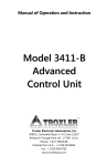
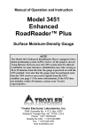
ASPHALT OR HARDENED CONCRETE SITE
NOTE
These directions also apply to taking a backscatter
measurement on soil.
Locate a smooth site on the asphalt. Fill the voids on open
mixes with sand or cement, ensuring that the total area filled
does not exceed approximately 10 percent of the bottom area of
the gauge. The gauge base must rest on the asphalt, not the
fill material! Ensure that the gauge does not rock. To ensure
accurate readings, the gauge base must be completely in
contact with the test material. If the gauge rocks, find a more
suitable test site. If taking a measurement around a core, the
gauge may be moved a few inches from the core to level it.
OFFSET FUNCTION
The gauge can be adjusted using an offset. The gauge applies
the offset to measurements until the offset is disabled or the
gauge is turned off. The gauge provides three offsets: density,
moisture, and trench.
Press 〈OFFSET〉 to access the Offset menu.
DENSITY OFFSET
To use a density offset, press 〈1〉 from the Offset menu. The
Density Offset menu shows the current density offset on the
second line. Press 〈1〉 to enable the displayed density offset or
〈2〉 to disable it. To enter a new density offset, press 〈3〉. The
gauge prompts for the density offset. Select the offset sign
(positive or negative), enter the density offset, and press
〈ENTER〉.
MOISTURE OFFSET
To use a moisture offset, press 〈2〉 from the Offset menu. The
Moisture Offset menu shows the four stored offset values (if
any) and the New and Disable options. To select a stored offset
value, press the number key that matches the displayed value.
To enter a new offset value, press 〈5〉. At the Select Offset
Source prompt, press 〈1〉 to enter a moisture offset manually,
or 〈2〉 to allow the gauge to derive the offset value. Follow the
gauge prompts to enter or derive the offset value. Upon
completion, the gauge displays the prompt Save This Value
for Later Use? Press 〈NO〉 to enable and use the offset
without storing it, or 〈YES〉 to enable the value and store it in
memory. The gauge can store the value in one of four memory
cells. Storing a new value in a cell will erase the old value. At
the Select memory cell prompt, use the number keys to store
the value.
To disable the moisture offset, press 〈6〉 from the Offset menu.
5
TRENCH OFFSET
To use a trench offset, press 〈3〉 from the Offset menu. The
Trench Offset menu shows the current offset values on the
second line. To enable the displayed trench offset, press 〈1〉. To
disable the trench offset, press 〈2〉. To enter a new trench offset,
press 〈3〉. As prompted by the gauge, select a position inside
the trench and the same distance from the wall as the test
measurements. Place the gauge on the standard block in this
position, set the source rod to the SAFE position, and press
〈ENTER/START〉. The gauge performs a trench count,
calculates the trench moisture and density offset values, enables
the trench offset, and returns to the Ready screen.
The trench offset is active for moisture measurements at all
source rod positions, and for density measurements in
backscatter position and direct transmission positions of less
than 4 inches.
Model 3430 Plus & 3440 Plus
Surface
Moisture-Density
Gauge
TESTING AND MEASUREMENT
Before taking any measurement, set the measurement mode by
pressing 〈MODE〉, then press the number key that matches the
desired mode. Check the count time. Enter a target value, if
desired. Prepare the test site.
To begin a reading, lower the source rod and press
〈ENTER/START〉. In the Automatic depth mode (Model 3440
Plus only), the gauge determines the source rod depth
automatically. In the Manual mode, the operator must enter the
source rod depth manually.
After taking readings, lift the gauge from the test site by the
source rod handle. This returns the source rod to the SAFE
position. When not taking readings, always keep the source rod
in the SAFE position.
After the measurement, the gauge displays the measurement
results. To store the reading, press 〈STORE〉 (see below).
For soil (direct transmission) measurements, the density depth
of measurement is the depth at which the source rod is placed
(except for backscatter mode, which is approximately 4 in.).
The moisture depth of measurement is determined by the
moisture (or hydrogen) content of the material being tested.
The following equations can be used to determine the
approximate depth of measurement.
Depth (inches) = 11 – (0.17 × M), where: M = moisture in pcf
or
Depth (mm) = 280 - (0.27 × M), where: M = moisture in kg/m3
STORAGE FUNCTION
Assign a project number before storing readings by pressing
〈PROJ〉. Select the desired option from the displayed menu. To
store readings, press 〈STORE〉. Follow the gauge prompts to
enter any additional project information.
6
QUICK
REFERENCE
CARD
Troxler Electronic Laboratories, Inc.
3008 Cornwallis Rd. • P.O. Box 12057
Research Triangle Park, NC 27709
Phone: 1.877.TROXLER
Outside the USA: +1.919.549.8661
Fax: +1.919.549.0761
www.troxlerlabs.com
PN 110888
March 2006
Edition 1.0
GAUGE START UP
NOTE
The operator should wear a dosimeter or radiation
badge when working with the Model 3430 Plus or
3440 Plus Surface Moisture-Density Gauge.
To turn on the gauge, press the power switch. Upon power-up,
the gauge briefly displays the model number, software version,
and serial number. It then performs a brief self-test, followed
by a display test. Following the two tests, the gauge enters a
300-second warmup period, then displays the Ready screen:
-READYg
04-08-2006 12:21 PM
Prj: TROXLER
Press <START>
NOTE
The symbol g in the upper right of the display
indicates that the GPS option is installed, the option is
enabled, and the gauge is receiving GPS satellite
signals. This option is available only on the Model
3440 Plus.
Gmb: ##.#
pcf
1: ##.#
2: ##.#
3: ##.#
4: ##.#
5: New
6: Disable
The menu shows the four stored target values (if any) and the
New and Disable options. To select a stored target value, press
the number key that matches the displayed target value.
To store a new target value, press 〈5〉. At the prompt, use the
number keys to enter the target value. Press 〈ENTER/START〉.
The gauge displays the value entered and asks if the operator
wants to store the value. To store the value, press 〈YES〉. The
gauge can store the value in one of four memory cells. Storing a
new value in a cell will erase the old value. At the Select
memory cell prompt, use the number keys to store the value.
To disable the target value, press 〈6〉.
THE STANDARD COUNT
To compensate for the source decay and to check proper
operation of the gauge, take a standard count each day that the
gauge is used.
Place the reference standard block on a dry, flat surface of
asphalt, concrete, or compacted soil at least 10 cm (4 in) thick.
The location should be at least 3 m (10 ft) from any building or
vertical structure and 10 m (33 ft) from any other nuclear gauge
or radioactive source.
GAUGE SETUP
COUNT TIME
To change the current count time (length of measurement),
press 〈SETUP〉 to display the Setup menu. Press 〈1〉 to access
the Count Time function. Use the numeric keys to select the
desired count time.
SET UNITS
The gauge can display measurement results in either U.S. units
(pcf) or metric (SI) units (kg/m3 or g/cm3). To select the units,
press 〈SETUP〉 to display the Setup menu. Press 〈2〉 to
display the Units menu. Select the new units using the
corresponding number key.
TARGET VALUES
To select or change a Marshall, Proctor, or voidless density
value or Marshall and voidless density pairs, press 〈TARGET〉.
The gauge displays the Target menu. To edit a target value,
press the number key that corresponds to that value. For
example, to edit the Gmb (Marshall) value, press 〈1〉.
The gauge displays the selected Target Value menu. The
Target Value menu for the Proctor value is shown on page 3.
2
Ensure that the top surface of the reference standard block and
bottom of the gauge are clean of debris. As shown at left, place
the gauge between the grooves on the reference standard block.
Place the source rod on your left and the right side of the gauge
against the metal butt plate on the block.
NOTE
Ensure that the source
rod is in the standard
(SAFE) position by
firmly tapping down on
the handle of the source
rod.
After taking a 240-sec standard count, the gauge displays the
density and moisture standards (DS and MS). The gauge also
displays P or F to show if the results fall within acceptable
limits. The DS should be within 1% and the MS should be
within 2% of the previous four standard counts. Troxler
recommends that the operator keep a daily log of the standard
count results, using Appendix D of the Model 3430 and 3440
Plus Manual of Operation and Instruction (user manual).
SITE PREPARATION
To ensure measurement accuracy, properly prepare the test site
before taking gauge measurements.
SOIL SITE
CAUTION
Safety glasses and a radiation dosimeter must be worn
during this procedure.
Locate a smooth site on the soil free from any large holes,
cracks, or debris. If necessary, smooth the surface by moving
the scraper plate in a back and forth motion. Fill any voids or
depressions with fine sand, ensuring that the total area filled
does not exceed approximately 10 percent of the bottom area of
the gauge. Strike off any excess fill. Place the scraper plate
back on the surface and press down slightly to level the surface.
DRILL ROD
EXTRACTION TOOL
SCRAPER PLATE/
DRILL ROD GUIDE
As shown at left, put
the drill rod through the
extraction tool and then
through one of the
guides on the scraper
plate. Place the drill rod
assembly on the test
site. Step on the scraper
plate. Hammer the drill
rod at least 50 mm (2
in.) deeper than the
desired test depth. The
drill rod increments
include the additional
depth.
Mark the test area.
Remove the drill rod by pulling straight up on the drill rod
extraction tool. Do not loosen the drill rod by moving it from
side-to-side.
Press 〈STD〉. The gauge
displays the last standard
count. To take a new
standard count, press
〈YES〉. With the gauge in
the standard count
position, press
〈ENTER/START〉 to
begin the standard count.
3
Place the gauge on the smoothed surface. Insert the source rod
into the hole. Release the trigger in the gauge handle and lower
the source rod to the correct depth. A click should be heard
when the source rod is locked into position. Gently slide the
gauge toward the keypad so the source rod touches the side of
the hole.
4