1
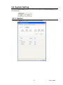
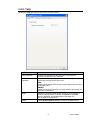
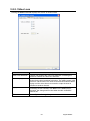
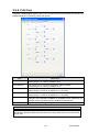
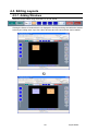
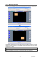
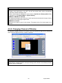
OPERATION MANUAL MV-410RGB Layout Editor Version 2.1- higher Table of Contents 1. Setup ............................................................................................................................................ 1 1-1. Overview............................................................................................................................... 1 1-2. System Requirements .......................................................................................................... 1 1-3. Operation Flow ..................................................................................................................... 1 1-4. Installing MV-410RGB Layout Editor.................................................................................... 2 1-5. Removing MV-410RGB Layout Editor ................................................................................. 5 1-6. Connections.......................................................................................................................... 6 1-7. PC Network Settings ............................................................................................................ 6 2. Starting / Exiting MV-410RGB Layout Editor ................................................................................ 8 2-1. Starting MV-410RGB Layout Editor ........................................................................................ 8 2-2. Exiting MV-410RGB Layout Editor ......................................................................................... 8 3. Main Screen and Dialog Boxes .................................................................................................... 9 3-1. Main Screen ......................................................................................................................... 9 3-1-1. MV-410RGB ID Boxes ................................................................................................. 9 3-1-2. File Buttons .................................................................................................................. 9 3-1-3. Layout Upload Buttons ............................................................................................... 10 3-1-4. Setting Buttons ............................................................................................................ 11 3-1-5. Layout Editing Area and Editing Tools ........................................................................ 11 3-2. System Setting ................................................................................................................... 15 3-2-1. System ....................................................................................................................... 15 3-2-2. Tally ............................................................................................................................ 17 3-2-3. Video Loss .................................................................................................................. 18 3-2-4. Full Screen ................................................................................................................. 19 3-2-5. Full Crop ..................................................................................................................... 20 3-3. Layout Setting .................................................................................................................... 21 3-3-1. Border ......................................................................................................................... 21 3-3-2. Title ............................................................................................................................. 22 3-3-3. Crop ............................................................................................................................ 23 4. Using MV-410RGB Layout Editor ............................................................................................... 24 4-1. Establishing Connection ..................................................................................................... 24 4-2. Creating and Loading Layout ............................................................................................. 25 4-2-1. Creating New Layout.................................................................................................. 25 4-2-2. Loading Existing Layout ............................................................................................. 26 4-2-3. Opening Saved Layout............................................................................................... 27 4-3. Editing Layouts ................................................................................................................... 28 4-3-1. Adding Windows ......................................................................................................... 28 4-3-2. Deleting Windows ...................................................................................................... 29 4-3-3. Moving Window .......................................................................................................... 30 4-3-4. Setting Window Size ................................................................................................... 31 4-3-5. Changing Channel of Window .................................................................................... 32 4-3-6. Changing Layer Order of Windows ............................................................................ 33 4-3-7. Changing Display Position of Title .............................................................................. 33 4-4. Saving Layout to MV-410RGB ............................................................................................ 34 4-5. Saving Layout as File on Computer.................................................................................... 34 4-6. Closing MV-410RGB Layout Editor .................................................................................... 34 5. Displaying Layout on MV-410RGB Output ................................................................................. 34 5-1. MV-410RGB ........................................................................................................................ 34 5-2. MV-410RGB Layout Editor.................................................................................................. 34 Trademark Microsoft ® Windows XP operating system is a trademark of Microsoft Corporation. .NET Framework is a trademark of Microsoft Corporation. Pentium ® is a trademark of Intel Corporation. 1. Setup 1-1. Overview MV-410RGB Layout Editor is a software to customize the layout of the MV-410RGB split screen from a computer. Up to 4 preset patterns (SPLIT 1 to 4) can be stored. Those stored layouts are easily recalled by using the SPLIT button on the front panel of MV-410RGB. MV-410RGB and a computer can be connected via LAN. 1-2. System Requirements To install MV-410RGB Layout Editor, your computer must meet the following requirements. OS CPU Memory Display Network port Network cable Software Windows® XP operating Windows® 7 operating Windows® 8 operating system SP2 or later system system (32/64-bit) Professional (32-bit) Professional (32/64-bit) Pentium® 4 processor Intel® Core™2 Duo Intel® Core™2 Duo processor processor 1.3 GHz or faster 2 GHz or faster 2 GHz or faster 512 MB or more 2 GB or more 2 GB or more Resolution of 1024 x 768pixels or better Must be capable of full color (24-bit) display Ethernet, at least one port 100BASE-TX/1000BASE-T 100BASE-TX: Category 5 or better 1000BASE-T : Category 6, or enhanced category 5 Microsoft® .NET Framework 4.0 (Supplied on the CD-ROM) Windows® Installer 4.5 (Supplied on the CD-ROM) 1-3. Operation Flow (1) Installing MV-410RGB Layout Editor (2) Connecting MV-410RGB Layout Editor installed PC to MV-410RGB (3) Starting MV-410RGB and MV-410RGB Layout Editor (4) Creating a split screen layout (5) Displaying a split screen layout 1 Layout Editor 1-4. Installing MV-410RGB Layout Editor (1) Load the supplied Installation CD-ROM into the PC, and open the CD-ROM drive. Run the file "setup.exe" to start the setup wizard. Double-click (2) If [.NET Framework 4.0] is not installed on your PC, the screen shown below is displayed. Click Accept. If [.NET Framework 4.0] is already installed on your PC, this screen is not displayed. (3) If [Windows Installer 4.5] is not installed on your PC, the screen shown below is displayed. Click Accept. If [Windows Installer 4.5] is already installed on your PC, this screen is not displayed. (4) If [.NET Framework 4.0] is not installed, the installation starts. 2 Layout Editor (5) When installation of [.NET Framework 4.0] is complete, the screen shown below is displayed requiring a reboot. Click Yes to reboot your PC. (6) After the setup wizard is started, click Next. (7) Select the installation directory. It is not necessary to change the folder. Select whether to install MV-410RGB Layout Editor for current user only or for all users. The default is set to the current user. When the settings are completed, click NEXT>. 3 Layout Editor (8) Click NEXT> to start the installation. (9) When installation is completed normally, the screen shown below is displayed. Click Close to quit the setup wizard. 4 Layout Editor 1-5. Removing MV-410RGB Layout Editor To remove MV-410RGB Layout Editor, follow the uninstallation procedure described in your operation system user's manual. The "Microsoft .NET Framework 4.0" and "Windows Installer 4.5" do not need to be removed. If your OS is Windows 8: 1) Open to or change to the Start menu screen. 2) Using a mouse, point to the upper-right corner of the screen to display the Charms Bar. Click on the Settings icon. 3) In the Settings window, select Control Panel. 4) In the Control Panel window, select Uninstall a program beneath Programs. 5) Select "MV-410RGB Layout Editor" to start uninstallation. * If the User Account Control dialog box appears, click Yes to continue the uninstallation. If your OS is Windows 7 (and in Category View): 1) Go to Start > Control Panel. Select Add or Remove Programs to display the window. 2) In the Add or Remove Programs window, select “MV-410RGB Layout Editor”, and click Remove to start the uninstallation. * If the User Account Control dialog box appears, click Yes to continue the uninstallation. If your OS is Windows XP: 1) Go to Start > Control Panel. Select Add or Remove Programs to display the window. 2) In the Add or Remove Programs window, select “MV-410RGB Layout Editor”, and click Remove to start the uninstallation. 5 Layout Editor 1-6. Connections To use MV-410RGB Layout Editor, connect MV-410RGB and PC over a LAN interface. Be aware that the cables and equipment used vary depending on the connection method. Use a crossover LAN cable to connect the computer directly to the MV-410RGB. Use a straight through LAN cable for the connection using a router or a hub. The communication standards for serial control over a LAN interface is as follows. Protocol TCP/IP Protocol Setting range: 0.0.0.0 to 255.255.255.255 However, there also are limitations on IP addresses set by the PC as shown below. Set the IP address in this range. . 192 IP address Subnet mask length Gateway MAC address . 2nd octet 1st octet 1st octet: 2nd octet: 3rd octet: 4th octet: 168 0 . 3rd octet 1 4th octet 1 to 223 (except 127) 0 to 255 0 to 255 1 to 254 * This is set in the menu screen on the main unit. * The default setting is 192.168.0.1. Setting range: 0 to 31 * This is set in the menu screen on the main unit. * The default setting is 24. Setting range: 0.0.0.0 to 255.255.255.255 * This is set in the menu screen on the main unit. * The value 0.0.0.0 signifies that the gateway has not been set. * The default setting is 0.0.0.0. This is already set at factory shipping (cannot be changed). * The setting can be confirmed in the menu screen on the main unit. 1-7. PC Network Settings The PC network settings need to match that of the MV-410RGB. The procedure for making the network settings at the PC vary depending on the OS, so refer to the OS manual for details. This setting example shows the case when connecting to the MV-410RGB with the default settings. The MV-410RGB default settings are shown below. IP address Subnet mask length Gateway 192. 168. 0.1 24 0.0.0.0 6 Layout Editor Setting in Windows 8: 1) Open [Control Panel] -> [Network and sharing Center]. 2) Click Ethernet adapter and select Properties. 3) Double click on [Internet Protocol Version 4 (TCP/IPv4)] to bring up the TCP/IP settings window. 4) Set the network settings as shown in the example below. Make a note of the settings before changing them in case you need to return the IP address to its original settings later. IP address for PC Subnet mask 192.168.0.yyy (yyy is any number from 2 to 254 except for the number set for the MV-410RGB unit and the gateway number. In this example, the setting is yyy=200.) Set to 255.255.255.0. Setting in Windows 7: 1) Open [Control Panel] -> [Network and Internet] -> [Network and Sharing Center]. 2) Click Local Area Connection and select Properties. 3) Double click on [Internet Protocol Version 4 (TCP/IPv4)] to bring up the TCP/IP settings. Setting in Windows XP with the default Start menu mode: Click Start on the taskbar, select "Settings" "Network Connections" and then right-click the "Local Area Connection" icon to open [Properties] window. Double-clicking "Internet Protocol (TCP/IP)" under the [General] tab opens the [Internet Protocol (TCP/IP) Properties] window. Then make the settings in the same way as above. When the settings are completed, click OK, and then close all setting windows. Setting in Windows XP with the Start menu setting changed to Classic: Click Start on the taskbar, select "Settings" "Network Connections" and then right-click the "Local Area Connection" icon to open [Properties] window. Double-clicking "Internet Protocol (TCP/IP)" under the [General] tab opens the [Internet Protocol (TCP/IP) Properties] window. Then make the settings in the same way as above. When the settings are completed, click OK, and then close all setting windows. 7 Layout Editor 2. Starting / Exiting MV-410RGB Layout Editor 2-1. Starting MV-410RGB Layout Editor 1) 2) 3) Starting in Windows 8: Open to or change to the Start menu screen. Right-click on an empty part of your desktop, select [All Apps]. Click on the [MV-410RGB Layout Editor] icon to start the program. * To launch multiple instances of MV-410RGB Layout Editor, right-click on the [MV-410RGB Layout Editor] icon and select "Open New Window." Starting in Windows 7: To start MV-410RGB Layout Editor, go to Start > Programs > FOR.A and select "MV-410RGB Layout Editor". 2-2. Exiting MV-410RGB Layout Editor To exit MV-410RGB Layout Editor, click the x button at the top-right corner of the screen. NOTE All unsaved changes will be lost when the application is closed. Save the current layout to MV-410RGB or to your computer before closing the application. 8 Layout Editor 3. Main Screen and Dialog Boxes 3-1. Main Screen After the application is started the screen shown below is displayed. File Buttons Layout Upload Buttons MV-410RGB ID boxes Setting Buttons Layout Editing Area 3-1-1. MV-410RGB ID Boxes (1) IP address Enter the IP address of MV-410RGB to be connected. (2) ID Enter the ID specified in MV-410RGB. (3) Password Enter the password specified in MV-410RGB. 3-1-2. File Buttons (1) New Creates a new layout. NOTE All unsaved changes will be lost when the layout is closed to start a new layout. Save the current layout to MV-410RGB or to your computer before creating a new layout. 9 Layout Editor (2) Open Opens a layout saved on the computer. NOTE All unsaved changes will be lost when a layout saved on the computer is opened. Save the current layout to MV-410RGB or to your computer before opening a layout. (3) Save Save the currently open layout on the computer. NOTE The MV-410RGB system settings as well as the layout settings are saved as a layout file. 3-1-3. Layout Upload Buttons (1) Layout Number Selects a layout number of the layout to be edited or saved. Up to 4 patterns can be saved to MV-410RGB. Once the layout number is selected, the layout is loaded from MV-410RGB into the layout editing area. NOTE Selecting the same number as the layout number of MV-410RGB allows users to easily check the layout, since the changes in the layout editing area are applied to MV-410RGB in real-time. However, all unsaved changes will be lost when MV-410RGB is powered off. Save the current layout to MV-410RGB before powering off MV-410RGB. Layout Number is empty right after the application is started. In this status, layouts can be created without communicating with MV-410RGB (off-line). The created layouts can be saved on the computer and loaded into MV-410RGB when connected. (2) Display Displays the layout selected in the Layout Number drop-down list on MV-410RGB output monitor. (3) Save Saves the current layout to MV-410RGB. NOTE All unsaved changes will be lost when MV-410RGB is powered off. Save the current layout to MV-410RGB before powering off MV-410RGB. (4) Send Sends the current layout to MV-410RGB. Normally you do not need to click the Send button since the changes of the layout are sent real-time to MV-410RGB. If the layouts in the layout editing area and MV-410RGB do not match due to a communication error, click the Send button. 10 Layout Editor 3-1-4. Setting Buttons (1) System The MV-410RGB system settings and full screen display settings can be made. See section 3-2. “System Setting” for details. NOTE The layout cannot be edited while the System Setting dialog box is displayed. To edit the layout, close the System Setting dialog box. (2) Layout The layout settings can be made for each layout separately. See section 3-3. “Layout Setting” for details. NOTE The layout cannot be edited while the Layout Setting dialog box is displayed. To edit the layout, close the Layout Setting dialog box. 3-1-5. Layout Editing Area and Editing Tools (1) (2) (1) Layout editing area base point The coordinate (0, 0) base point of the layout editing area is the top-left corner of the area. The X coordinate value increases from left to right. (The right end is the highest.) The Y coordinate value increases from top to bottom. (The bottom end is the highest.) (2) Window base point The location of a window is determined by the X coordinate of the left edge of the window, and the Y coordinate of the top edge of the window. 11 Layout Editor NOTE The valid coordinate range for placing a window varies depending on the output resolution. (3) Output Resolution Displays the output resolution of the selected layout. NOTE The output resolution can only be selected when creating a new layout. The resolution of the layout loaded from MV-410RGB or the layout opened from the computer cannot be changed. (4) Window Display Position (X, Y) Displays the display position of the selected window. Also the window display position can be adjusted by changing the numeric values. NOTE Window Display Position for both X and Y can be adjusted in units of 2 pixels. (5) Window Size (W, H) Displays the size of the selected window. Also the window size can be adjusted by changing the numeric values. If Aspect Ratio is set to other than Free, changing either of W (width) or H (height) changes the other automatically. NOTE Window Size for both Width and Height can only be adjusted in units of 8 pixels. Due to this limitation, the specified aspect ratio may not always be applied accurately. (6) Undo Cancels the performed actions. (7) Redo Cancels the undo commands. (8) Aspect Ratio Changes the aspect ratio of the selected window. The window size can be changed while retaining the specified aspect ratio. 16:9 4:3 1:1 Free Used for the window that displays an image of 16:9 such as 1360 x 768. Used for the window that displays an image of 4:3 such as 1024 x 768. Selectable for the clock window only. The window size can be changed without retaining the aspect ratio. NOTE The Aspect Ratio drop-down list to the left of the 1 button is for the video windows. The Aspect Ratio drop-down list to the right of the C button is for the clock window. 12 Layout Editor (9) Add / Select Window Selects a window for changing the settings. Clicking either of 1, 2, 3, or 4 selects the window of the selected number. Clicking C selects the clock window. If the selected window is not displayed in the layout editing area, the window is added to the layout editing area. NOTE The number displayed in a window on the layout edit screen and the channel number of the input video signal to be displayed on the monitor are the same. (10) Delete Window Clicking Delete deletes the selected window from the layout edit screen. Clicking Delete All deletes all windows from the layout edit screen. (11) Select Preset Pattern Clicking any one of the split screen icons at the left of the layout editing area selects a preset pattern of split screen. If multiple patterns of the same number split screen exist, the displayed pattern can be changed to other pattern by the lever beneath the split screen icons. Every click on the split screen icon also changes the pattern display. (12) Add / Move 1/16 size window Clicking any one of the add 1/16 size window icon at the right of the layout editing area adds a 1/16 size window at the place each icon depicts. Every click add a window in a row shown in the icon. The arrow button beneath the add 1/16 size window icon changes the direction of the window line opposite. Five buttons under the icons instantly move a window right next to the other window in each direction. If there is no window in the direction, the window is moved to the edge of the layout editing area. The center button positions a window at the center of the layout editing area. (13) Front (Bring to front) Arranges the selected window to the front. (14) Back (Send to back) Arranges the selected window to the back. (15) Fit Screen Maximizes the window to best fit the selected window size. If Aspect Ratio is set to other than Free, the aspect ratio is retained. (16) Width x 2 Sets the width of the selected window to double the width of the original window. If Aspect Ratio is set to other than Free, the aspect ratio is retained. 13 Layout Editor (17) Height x 2 Doubles the height of the selected window to double the height of the original window. If Aspect Ratio is set to other than Free, the aspect ratio is retained. (18) Width 1/2 Sets the width of the selected window to half the width of the original window. If Aspect Ratio is set to other than Free, the aspect ratio is retained. (19) Height 1/2 Sets the height of the selected window to half the height of the original window. If Aspect Ratio is set to other than Free, the aspect ratio is retained. (20) Deselect Deselects the selected window. (21) Title Display Position (X, Y) Displays the display position of the selected window title. Also the title display position can be adjusted by changing the numeric value. The X value represents the position of the left edge of title and the Y value represents the top edge of title. 14 Layout Editor 3-2. System Setting Clicking the System Setting button in the main screen displays the System Setting dialog box as shown below. 3-2-1. System Clicking the System tab displays the screen as shown below. 15 Layout Editor Item Date/Time Clock Type Display Mode Frequency Apply Close Description Click Change and then enter the date and time set for MV-410RGB. Clicking Set applies the settings to MV-410RGB. Selects the type of clock display. * Followings are the images to give you an idea of each type of clocks. <Analog 1> <Analog 2> <Digital 1> <Digital 2> Dark frame Light frame Selects the screen display mode. MODE1 [In Full screen display] Displays the title and audio level meters without overlapping on the video image. The aspect ratio of the input signal is retained. [In Split screen display] Auto detects the aspect ratio of the input video signals and maximizes the images to best fit the each window while retaining the aspect ratio. MODE2 [In Full screen display] Overlaps the title and audio level meters on the video image. The aspect ratio of the input signal is retained. [In Split screen display] Auto detects the aspect ratio of the input video signals and maximizes the images to best fit the each window while retaining the aspect ratio. MODE3 [In Full screen display] Maximizes the image to best fit the window. The aspect ratio of the input signal is not retained. The title and audio level meters are overlapped on the video image. [In Split screen display] Maximizes the image to best fit the window. The aspect ratio of the input signal is not retained. Selects frequency for the MV-410RGB output signal from among 60Hz, 59.94Hz, and 50Hz. Those are approximate frequencies. See the MV-410RGB Operation Manual, section 10-1. "Specifications" for details. Applies the changes made in this screen to MV-410RGB. To save the settings in MV-410RGB, click Save on the main screen; otherwise, the changes will be lost when the MV-410RGB is powered off. Closes System Setting dialog and returns to main screen. 16 Layout Editor 3-2-2. Tally Clicking the Tally tab displays the screen as shown below. Item Tally Detection Simultaneous tallies indication Apply Close Description Enables and disables the tally detection. Selecting the checkbox enables the tally detection. Sets the color of tally display for when the red tally and the green tally are input at the same time. RED Displays a red frame if the red tally and the green tally are input at the same time. UMBER Displays an orange frame if the red tally and the green tally are input at the same time. Applies the changes made in this screen to MV-410RGB. To save the settings in MV-410RGB, click Save on the main screen; otherwise, the changes will be lost when the MV-410RGB is powered off. Closes System Setting dialog and returns to main screen. 17 Layout Editor 3-2-3. Video Loss Clicking the Video Loss tab displays the screen as shown below. Item Video Loss Detection Alarm Display Time Apply Close Description Enables and disables the video loss detection. Selecting the checkbox enables the video loss detection. When a video loss is detected, an alarm is displayed within the window for the time length set in this box. The setting range is 00 second to 100 seconds. The value 00 second continues the alarm display until the video loss is recovered or output channel is switched to another channel. Applies the changes made in this screen to MV-410RGB. To save the settings in MV-410RGB, click Save on the main screen; otherwise, the changes will be lost when the MV-410RGB is powered off. Closes System Setting dialog and returns to main screen. 18 Layout Editor 3-2-4. Full Screen Clicking the Full Screen tab displays the screen as shown below. Item Description Full Screen Selects the output resolution for full screen display. The available Output Resolution settings are as follows: 1280 x 1024, 1360 x 768, 1600 x 1200, 1920 x 1200 1440 x 900, 1680 x 1050, 1920 x 1080, 1280 x 720 Title Display Shows and hides the title. Selecting the checkbox shows the title. Title Sets the title to be displayed. Up to 16 characters can be used. Text Size Selects the text size. The available settings are: SMALL, MEDIUM, and LARGE. Color Selects the title color. The available settings are: WHITE, YELLOW, GREEN, CYAN, RED, MAGENTA, BLUE, GRAY, and BLACK. Apply Applies the changes made in this screen to MV-410RGB. To save the settings in MV-410RGB, click Save on the main screen; otherwise, the changes will be lost when the MV-410RGB is powered off. Close Closes System Setting dialog and returns to main screen. 19 Layout Editor 3-2-5. Full Crop Clicking the Full Crop tab displays the screen as shown below. On this page, the size to crop images displayed in full screen mode can be set. Item Crop (Top) Crop (Bottom) Crop (Left) Crop (Right) Apply Close Description Sets how much to crop from the top edge of images. Setting range: 0 to 1200 (in multiples of 4) Sets how much to crop from the bottom edge of images. Setting range: 0 to 1200 (in multiples of 4) Sets how much to crop from the left side of images. Setting range: 0 to 960 (in multiples of 4, 1=2 pixels) Sets how much to crop from the right side of images. Setting range: 0 to 960 (in multiples of 4, 1=2 pixels) Applies the changes made in this screen to MV-410RGB. To save the settings in MV-410RGB, click Save on the main screen; otherwise, the changes will be lost when the MV-410RGB is powered off. Closes System Setting dialog and returns to main screen. IMPORTANT If the specified crop size exceeds the screen size of the input format, the image display will become improper. Make sure that the total of crop sizes does not to exceed the screen size. 20 Layout Editor 3-3. Layout Setting Clicking the Layout Setting button in the main screen displays the Layout Setting dialog box as shown below. The parameters for each layout can be set separately with this dialog box. 3-3-1. Border Clicking the Border tab displays the screen as shown below. Item Border Display Border width (Top) Border width (Bottom) Border width (Left) Border width (Right) Border Color Apply Close Description Selects whether to show or hide the borders. Sets the top border line width in the range from 0 to 50. Sets the bottom border line width in the range from 0 to 50. Sets the left border line width in the range from 0 to 50. Sets the right border line width in the range from 0 to 50. Selects the border color. The available settings are: WHITE, YELLOW, CYAN, MAGENTA, BLUE, GRAY, and BLACK Applies the changes made in this screen to MV-410RGB. To save the settings in MV-410RGB, click Save on the main screen; otherwise, the changes will be lost when the MV-410RGB is powered off. Closes Layout Setting dialog and returns to main screen. IMPORTANT The minimum size of windows is 120(W) x 80(H). Displaying video images requires the area larger than 96(W) x 56(H). Therefore, if the border width is set too wide for the small window, the border width is automatically narrowed. 21 Layout Editor 3-3-2. Title Clicking the Title tab displays the screen as shown below. Item Title Display Title Text Size Color Apply Close Description Shows and hides the title. Selecting the checkbox shows the title. Sets the title to be displayed. Up to 16 characters can be used. Selects the text size. The available settings are: SMALL, MEDIUM, and LARGE. Selects the title color. The available settings are: WHITE, YELLOW, GREEN, CYAN, RED, MAGENTA, BLUE, GRAY, and BLACK. Applies the changes made in this screen to MV-410RGB. To save the settings in MV-410RGB, click Save on the main screen; otherwise, the changes will be lost when the MV-410RGB is powered off. Closes Layout Setting dialog and returns to main screen. 22 Layout Editor 3-3-3. Crop Clicking the Crop tab displays the screen as shown below. On this page, the size to crop images of each channel displayed in split screen mode can be set. Item Crop (Top) Crop (Bottom) Crop (Left) Crop (Right) Apply Close Description Sets how much to crop from the top edge of images. Setting range: 0 to 1200 (in multiples of 4) Sets how much to crop from the bottom edge of images. Setting range: 0 to 1200 (in multiples of 4) Sets how much to crop from the left side of images. Setting range: 0 to 960 (in multiples of 4, 1=2 pixels) Sets how much to crop from the right side of images. Setting range: 0 to 960 (in multiples of 4, 1=2 pixels) Applies the changes made in this screen to MV-410RGB. To save the settings in MV-410RGB, click Save on the main screen; otherwise, the changes will be lost when the MV-410RGB is powered off. Closes System Setting dialog and returns to main screen. IMPORTANT If the specified crop size exceeds the screen size of the input format, the image display will become improper. Make sure that the total of crop sizes does not to exceed the screen size. 23 Layout Editor 4. Using MV-410RGB Layout Editor 4-1. Establishing Connection To start MV-410RGB Layout Editor, go to Start > Programs > FOR.A and select "MV-410RGB Layout Editor". After the application is started the screen shown below is displayed. Enter the IP address, ID and password of MV-410RGB that you wish to connect. The default settings of MV-410RGB are as follows: IP address: ID: Password: 192.168.0.1 ROOT 00000 a communication error occurs as shown above, make sure that the IP Ifaddress, ID, and password are set correctly. 24 Layout Editor 4-2. Creating and Loading Layout This section explains how to create a new layout or edit a layout loaded from MV-410RGB. The created layout can also be saved on the computer and reloaded for editing. The output resolution can only be selected for the newly created layouts and it cannot be changed for the layouts loaded from MV-410RGB or the layouts stored in the computer. 4-2-1. Creating New Layout (1) To create a new layout, select a layout number from 1-4 and click the New button in File at the top of the main screen. (2) The Output Resolution dialog box is displayed. Set the output resolution and click OK. (3) Edit the layout in the layout editing area that is currently opened. For example, add and move windows, or change the window size. See section 4-3. “Editing Layouts” for details. 25 Layout Editor 4-2-2. Loading Existing Layout To edit a layout in MV-410RGB, first select a layout number from the Layout Number drop-down list in MV-410RGB in the main screen. The layouts of the layout numbers 1-4 correspond to the layouts of the 1 – 4 VIDEO SELECT buttons on the front panel of MV-410RGB. Selecting a layout loads and displays the layout in the layout editing area as shown below. Edit the layout. (See section 4-3 “Editing Layouts” for details.) Clicking the Display button displays the layout selected in the Layout Number drop-down list on MV-410RGB output screen. If the editing layout and the layout output from MV-410RGB matches, users can easily check the layout, since the changes in the layout editing area are applied to MV-410RGB in real-time. NOTE The output resolution can only be selected when creating a new layout. The resolution of the layout loaded from MV-410RGB or the layout stored in the computer cannot be changed. 26 Layout Editor 4-2-3. Opening Saved Layout (1) To edit the layout saved on the computer, click the Open button in File. (2) Selecting a layout file and clicking Open opens the layout. NOTE The output resolution can only be selected when creating a new layout. The resolution of the layout loaded from MV-410RGB or the layout stored in the computer cannot be changed. 27 Layout Editor 4-3. Editing Layouts 4-3-1. Adding Windows Windows can be added using the buttons 1, 2, 3, 4, and C. Clicking the button of window that is not displayed in the layout editing area adds the window to the layout editing area. Up to four video windows and one clock window can be added. 28 Layout Editor 4-3-2. Deleting Windows To delete a window, select a window and click Delete. To delete all windows in the editing are, click Delete All. A window can also be deleted by selecting a window and choosing Delete from the right-click menu. 29 Layout Editor 4-3-3. Moving Window To move a window, drag the window to the desired position and release the mouse button. A window can also be moved by changing the numeric values in X and Y at the top of the edit window or using the arrow keys on the keyboard. (Select the window first.) Only one window can be moved at a time. NOTE When a window is moved, its title also move along with the window. The title located outside the window is moved inside if it reaches to the edge of the edit screen. 30 Layout Editor 4-3-4. Setting Window Size To change the window size, drag the edge of the window until the desired window size is obtained and release the mouse button. The window size can also be adjusted by selecting a window and changing the numeric values in W and H. If Aspect Ratio is set to other than Free, the size can be adjusted while retaining the aspect ratio. window size can also be changed by clicking the Fit Screen, Double The Width, Double Height, Half Width, and Half Height buttons. The actual video display is within the area left after the removal of areas for tally and border displays from the set window size. 31 Layout Editor NOTE ■ The minimum window size is 120 (W) x 80 (H). However, due to the minimum video display area requirement of 96 (W) x 56 (H), the border width will be automatically reduced to obtain the display area. ■ How a video signal is displayed in each window in Split Screen Display Mode differs depending on the Display Mode in System Setting. If MODE1 or MODE2 is selected Auto detects the aspect ratio of the input video signal and maximizes the image to best fit the window while retaining the aspect ratio. If MODE3 is selected Maximizes the image to best fit the window. The aspect ratio of the input signal is not retained. 4-3-5. Changing Channel of Window To change the display channel of a window, select the window and right-click to display the menu. From the right-click menu, choose a channel. NOTE Displaying the video signal of the same channel to multiple windows is not possible. If the channel that is already existed in the layout editing area is chosen, the window (channel) numbers will be exchanged. 32 Layout Editor 4-3-6. Changing Layer Order of Windows To change the layer order of overlapped windows, follow the instruction below. First select a window you wish to change the layer order. To bring the window to the front, click Front. To send the window to the back, click Back. The layer order can also be changed by selecting a window and choosing To Front or To Back from the right-click menu. 4-3-7. Changing Display Position of Title To change the display position of a title, select the window of the title that you wish to move and choose Title > Set Position from the right-click menu. The title moves along with the cursor as you drag the mouse. Move the cursor to the desired position and click the left mouse button. The display position of a title can also be adjusted by selecting a title and changing the numeric values in X and Y at the bottom of the edit window. the display position of the title to the default value, choose Title > ToSetreset to Default from the right-click menu. 33 Layout Editor 4-4. Saving Layout to MV-410RGB Once the connection between MV-410RGB and Layout Editor is established, the changes of the layout are applied real-time to MV-410RGB. However, since the changes are not backed up to the memory, unsaved changes will be lost when MV-410RGB is powered off. To save changes to MV-410RGB, click the Save button in MV-410RGB in the main screen. 4-5. Saving Layout as File on Computer To save the created layout as a file on the computer, click the Save button in File and give a desired name. The saved file can be loaded by clicking the Open button in File. 4-6. Closing MV-410RGB Layout Editor To close the application, Click × at the top-right corner of the screen. 5. Displaying Layout on MV-410RGB Output 5-1. MV-410RGB Pressing the SPLIT button on the front panel of MV-410RGB and pressing either of 1, 2, 3, or 4 button displays a pattern of four patterns preset in MV-410RGB Layout Editor. 5-2. MV-410RGB Layout Editor Choose a layout number from the Layout Number drop-down list and press the Display button. 34 Layout Editor


![取扱説明書[PDF:917.1KB]](http://vs1.manualzilla.com/store/data/006647219_3-48c69c479b4781dd2590581ac1670148-150x150.png)
![レイアウトエディタ取扱説明書[PDF:1.2MB]](http://vs1.manualzilla.com/store/data/006720139_2-b8421550bb6e4f5edd4e8be3b0604aff-150x150.png)