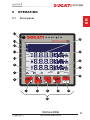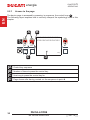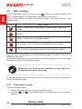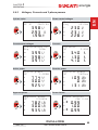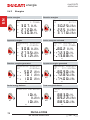
1
DUCA-LCD96
468001289
DUCA-LCD96 485
468001291
DUCA-LCD96-ETH
468001296
DUCA-LCD96-PROFI
468001294
DUCA-LCD96 485-RELE
468001293
DUCA-LCD96 485-IO
468001292
DUCA-LCD96 BASE
468001288
NETWORK ANALYSER
Assembly and use instructions
DUCA-LCD96
EN
energia
CHAPTER 1
energia
SUMMARY
1.1 Reference regulations and conformity....................................................5
1.2 Use and storage of the manual.................................................................6
1.2.1 Storing .....................................................................................................6
1.2.2 Copyright..................................................................................................6
1.3 General safety warnings............................................................................7
2 PACKAGING CONTENTS
2.1 Removal of packaging...............................................................................8
2.2 Description of the contents.......................................................................9
3 TECHNICAL CHARACTERISTICS
3.1
3.2
3.3
3.4
3.5
Description of the device........................................................................10
Measuring functions................................................................................10
Models....................................................................................................... 11
Overall dimensions ................................................................................12
Technical data...........................................................................................13
4 INSTALLATION
4.1 Assembly..................................................................................................18
4.2 Disassembly.............................................................................................19
4.3 Wiring diagrams.......................................................................................20
4.3.1 Wiring diagrams......................................................................................22
4.3.2 Inputs and outputs connections..............................................................24
4.4 Configurations for first use.....................................................................26
5 OPERATING
5.1 Front panel................................................................................................27
5.2 Use of device............................................................................................29
5.2.1 Access to the page.................................................................................30
5.3 Configuration of the SETUP device........................................................31
5.3.1 Control keys............................................................................................32
5.3.1.1
Data entry......................................................................................................33
5.3.2.1
5.3.2.2
5.3.2.3
Password creation.........................................................................................34
Password modification...................................................................................35
Password entry..............................................................................................35
5.3.4.1
5.3.4.2
5.3.4.3
5.3.4.4
5.3.4.5
5.3.4.7
5.3.4.8
5.3.4.9
5.3.4.10
5.3.4.11
Type of entry..................................................................................................38
Set CT ratio...................................................................................................40
Set VT ratio....................................................................................................41
Average time.................................................................................................42
Current threshold for T2 hour counter........................................................... 42
Generation.....................................................................................................44
Euro/energy factor.........................................................................................45
CO2/energy factor.........................................................................................45
Back lighting..................................................................................................46
Energy saving................................................................................................46
5.3.2 Password menu......................................................................................34
5.3.3 Reset menu............................................................................................37
5.3.4 Configuration menu................................................................................38
DUCA-LCD96
Rev. 1.0
NETWORK ANALYSER
3
EN
1 GENERAL INFORMATION
energia
CHAPTER 1
SUMMARY
EN
5.3.5 Digital output menu.................................................................................47
5.3.5.1
5.3.5.2
5.3.5.3
5.3.5.4
5.3.5.5
5.3.5.6
5.3.5.7
Digital output mode........................................................................................47
Energy value for pulse...................................................................................48
Alarm1 or alarm2(*) parameter...................................................................... 49
Alarm 1 or 2 threshold...................................................................................50
Alarm 1 or 2 activation...................................................................................50
Alarms 1 or 2 activation delay....................................................................... 51
Alarm 1 or 2 hysteresis..................................................................................51
5.3.6.1
5.3.6.2
5.3.6.3
5.3.6.4
5.3.6.5
Alarm 3 or 4 parameter (*).............................................................................52
Alarm 3 or 4 threshold...................................................................................53
Alarm 3 or 4 activation...................................................................................53
Alarms 3 or 4 activation delay....................................................................... 54
Alarm 3 or 4 hysteresis..................................................................................54
5.3.7.1
5.3.7.2
5.3.7.3
5.3.7.4
5.3.7.5
5.3.7.6
Outputs span.................................................................................................55
Output 1 parameter.......................................................................................56
Output 2 parameter.......................................................................................56
Input pulses factors.......................................................................................57
External synchronism....................................................................................57
Output associated parameter table............................................................... 58
5.3.8.1
5.3.8.2
5.3.8.3
5.3.8.4
5.3.8.5
5.3.8.6
PROFIBUS address (only DUCA-LCD96-PROFI)......................................... 59
Serial protocol................................................................................................60
Address.........................................................................................................60
Baud rate.......................................................................................................61
Parity type......................................................................................................61
Number of stop bits.......................................................................................62
5.3.6 Alarm output menu.................................................................................52
5.3.7 I/O card menu.........................................................................................55
5.3.8 Communication menu.............................................................................59
5.3.9 Language menu......................................................................................63
5.3.10Self-diagnosis menu...............................................................................64
5.3.11 Info menu................................................................................................65
5.3.12SETUP mode exit...................................................................................65
5.3.13Setup parameters table and factory settings..........................................66
5.4 Data reading.............................................................................................68
5.4.1 Default page setting................................................................................68
5.4.2 Voltages, Currents and 3-phase powers.................................................69
5.4.3 Energies..................................................................................................70
5.4.4 Voltage, Currents and single phase 3-phase Powers.............................72
5.4.5 THDF, Alarms, Timer and input pulses...................................................73
5.4.6 Maximums..............................................................................................75
5.4.7 Minimums...............................................................................................76
5.4.8 Averages.................................................................................................77
5.4.9 Maximum demand..................................................................................77
6 TROUBLESHOOTING
6.1 Problems, causes, solutions...................................................................78
6.1.1 Error codes ............................................................................................79
4
DUCA-LCD96
NETWORK ANALYSER
Rev. 1.0
CHAPTER 1
energia
GENERAL INFORMATION
1.1
GENERAL INFORMATION
Reference regulations and conformity
EN
1
2006/95/CEE
93/68/CEE (Low-Voltage Directive).
Electrical safety
IEC 61010-1
Electromagnetic compatibility
89/336/CEE
Use of hazardous substances
UE 2002-95-CE – RoHS
Measuring instruments
IEC 60688
IEC 61326-1
IEC 62053-21
IEC 62053-23
IEC 62053-31
Degree of protection
IEC 60529
Standardised dimensions for the panel
IEC 61554
DUCA-LCD96
Rev. 1.0
NETWORK ANALYSER
5
energia
1.2
CHAPTER 1
GENERAL INFORMATION
Use and storage of the manual
EN
Carefully read this manual and adhere to the indications
described prior to using the device.
This manual contains all of the safety information, the technical aspects and the
operating necessary to ensure the correct use of the device and maintain it in safe
conditions.
1.2.1
Storing
The manual must be stored close to the device; safe from liquids and anything else
which may compromise its leggibility.
The manual and the declaration of conformity are both an integral part of the device
until it is dismantled.
If the manual is lost or illegible please request a copy from the manufacturer.
1.2.2
Copyright
The copyright of this manual is the property of DUCATI Energia S.p.A.
This manual contains texts, designs and illustrations of a technical nature which must
not be disclosed or transmitted to third parties, even partially, without the written
authorisation of DUCATI Energia S.p.A.
6
DUCA-LCD96
NETWORK ANALYSER
Rev. 1.0
CHAPTER 1
energia
GENERAL INFORMATION
1.3
General safety warnings
••
••
••
••
••
••
••
••
••
••
••
••
••
EN
Non-adherence to the following points can lead to serious
injury or death.
Use the suitable personal protection devices and adhere to the current
regulations governing electrical safety.
This device must be installed exclusively by qualified personnel who have
read all of the information relative to the installation.
Check that the voltage supply and measurement are compatible with the range
permitted by the device.
Ensure that all current and voltage supplies are disconnected prior to carrying
out any controls, visual inspections and tests on the device.
Always assume that all circuits are under voltage until they are completely
disconnected, subjected to tests and labelled.
Disconnect all of the power supply prior to working on the device.
Always use a suitable voltage detection device to check that the supply is
interrupted.
Pay attention to any dangers and carefully check the work area ensuring that
no instruments or foreign objects have been left inside the compartment in
which the device is housed.
The correct use of this device depends on a correct manipulation, installation
and use.
Failure to adhere to the basic installation information can lead to injuries as well
as damage to the electric instruments or to any other product.
NEVER connect an external fuse in by-pass.
Disconnect all of the input and output wires before carrying out a dielectric
rigidity test or an insulation test on an instrument in which the device is installed.
The tests carried out at a high voltage can damage the device's electronic
components.
DUCA-LCD96
Rev. 1.0
NETWORK ANALYSER
7
energia
EN
2
2.1
CHAPTER 2
PACKAGING CONTENTS
PACKAGING CONTENTS
Removal of packaging
We recommend that the packaging is stored in a suitable
location in compliance with the warranty terms
8
DUCA-LCD96
NETWORK ANALYSER
Rev. 1.0
CHAPTER 2
energia
PACKAGING CONTENTS
2.2
Description of the contents
EN
The packaging includes:
1) network analyser
2) user manual
3) calibration certificate
4) mini CD with technical documentation
5) assembly accessories
Prior to using the product read the documentation attached
and strictly adhere to the indications provided.
CE
Se
1
2
ria
RT
IFI
CA
TO
DU
l N
DI
CO
LL
CA
AU
ene
DO
/ T
E
rgia
T R
um
Calib
468 LCD
ber
EP
Cer ration
9
.00
: …
OR
tifie
.12 6 48
……
d by System
T
5
:…… : …
91
……
…… ………
Para
……
……
…
met
…… ………
…
er
…
……
…
……
Rat
…… ………
ed
……
…
……
V1
valu
……
……
…
es
…… ………
……
……
…
…
….
…… ………
Mea
……
…
sure
…… ………
V rm
V2
d va
….
……
…
s
lues
…… …
Erro
…..
V rm
….
s
at fu r percen
V rm
ll sc
V rm
V3
ale. tage
s
….
s
V rm
V rm
s
….
s
%
V rm
V rm
s
I1
….
s
%
V rm
V rm
s
….
s
%
V rm
A
s
rm
…
I2
s
.
%
V rm
A rm
s
s
….
%
A rm
s
A rm
I3
….
%
s
A rm
s
A rm
….
%
s
A rm
A rm
s
Firm
….
%
s
A rm
Acc ware
A rm
ver
s
s
D a uracy
sio
%
n:…
t
A rm
C h e : … …class
……
s
:
eck
%
e r : … … …± 0 . 5 % … … …
A rm
……
……
s
… … … … … at full
……
%
… … … … sca
le ( ………
……
…
… … … … … ±1 dig ………
%
it)
……
…
…
… … … … at 20 ………
°C
…… … …
……
……
…… … …
DU
…… … …
…… … …
4013 C A T
2 BO I e
…… … …
n
LOG
……
NA e r g i
…
- Vi
a
aM
.E.L
s.p
epid
energia
.a.
o, 18
2 - C.
P. 31
59 Bo
Pone
nte
- Te
l. 05
1/40
4140
- Te
lefa
S
3
4
x: 40
2040
5
DUCA-LCD96
Rev. 1.0
NETWORK ANALYSER
9
energia
EN
3
3.1
CHAPTER 3
TECHNICAL CHARACTERISTICS
TECHNICAL CHARACTERISTICS
Description of the device
The DUCA-LCD96 network analyser is an instrument that measures of the main
electric quantities on 3-phase and monophase networks designed for the monitoring
and the local or remote analysis of:
•• electrical parameters of systems in low or medium voltage;
•• system energy consumption.
3.2
Measuring functions
All of the DUCA-LCD96 series models are able to measure and process the
quantities shown below.
1) Voltages (phase neutral and concatenated) and relative peak values;
2) Currents and relative peak values;
3) Power factors or PF phases and the 3-phase system, with distinction icon between
the inductive and capacitive load;
4) Frequency (measured on L1-N phase);
5) Active, reactive and apparent phase energies and the 3-phase system on 2
quadrants (with automatic recognition function of the AT directions);
6) Active, reactive and apparent power phases and the 3-phase system on 4 quadrants
(monitoring of energy aborbed and generated by the system);
7) Average power values on a time period programmed by the user;
8) Maximum calculated demand on active and apparent power;
9) Voltage and current THdF expressed in absolute and percent values;
10) T1 increase total operating hour counter and T2 decrease partial hour counter;
11) Balance of active, reactive and apparent energy of 3-phase system,
balance = absorbed energy - generated energy;
12) Balance of the "partial" active, reactive and apparent energies of the 3-phase system
on 4 quadrants in a period that can be programmed by the user, balance =
energy absorbed - energy generated;
The refresh rate (for each value available on the display) is 2
times/second.
10
DUCA-LCD96
NETWORK ANALYSER
Rev. 1.0
CHAPTER 3
energia
TECHNICAL CHARACTERISTICS
Models
Serial
communication
protocol
Models
Inputs and outputs
DUCA-LCD96
2 outputs programmable with pulses
or threshold alarms
DUCA-LCD96 485
2 outputs programmable with pulses
Modbus RTU
or threshold alarms
DUCA-LCD96-ETH
2 outputs programmable with pulses
Modbus TCP/IP
or threshold alarms
DUCA-LCD96-PROFI
2 outputs programmable with pulses
Profibus DP
or threshold alarms
EN
3.3
2 electromechanical relays 16A AC1
- 3A AC15
Modbus RTU
2 outputs programmable with pulses
or threshold alarms
2 analog outputs 4 -20 mA
3 inputs for external pulse reading
DUCA-LCD96 485-IO
Modbus RTU
2 outputs programmable as pulses
or threshold alarms
DUCA-LCD96 485RELE
2 outputs programmable with pulses
DUCA-LCD96 BASE or threshold alarms.
Current input stage with Shunt.
All of the models have the following in common:
•• multivoltage supply voltage;
•• multilanguage display with scrolling text;
•• self-diagnosis function for the installation control;
•• settiing of a safety password;
•• T1 and T2 hour counter.
DUCA-LCD96
Rev. 1.0
NETWORK ANALYSER
11
CHAPTER 3
energia
3.4
TECHNICAL CHARACTERISTICS
Overall dimensions EN
A
E
D
F
e n e r g i a
DUCA-LCD96
B
C
VIP
A
B
C
E
L
MIX
MAX
MIN
AVG
OK
SETUP
D
E
F
96 mm
96 mm
92 mm
77 mm
57 mm
20 mm
X
IEC 61554
X
Y
12
92 -0+0,8 mm
92 -0+0,8 mm
Y
DUCA-LCD96
NETWORK ANALYSER
Rev. 1.0
CHAPTER 3
energia
TECHNICAL CHARACTERISTICS
Technical data
Voltage range
Frequency range
Protection fuse
Power consumption
Measurement type
Voltage
Current
Frequency
Power factor
Active power
Active energy
Voltage
Current
Frequency
Power factor
Auxiliary power supply
from 24 to 240 a.c./d.c.
[V] from 48 to 240 a.c../d.c.DUCA-LCD96-ETH,
DUCA-LCD96-PROFI, DUCA-LCD96 485-IO
[Hz] 45 ÷ 65
T 0,5 A from 24 V to 100 V
T 0.25 A from 24 V to 100 V
[VA] 7 max
Sampling TRMS
Accuracy class
±0,5% F.S. ±1 digit
±0,5% F.S. ±1 digit
40.0 ÷ 99.9: ±0,2% ±0,1
[Hz]
100 ÷ 500: ±0,2% ±1
±1% ±1 digit
(from cosΦ= 0,3 Inductive
to cosΦ= 0,3 Capacitive)
±1% ±0,1% F.S
(from cosΦ= 0,3 Inductive
to cosΦ= 0,3 Capacitive)
Class 1
Measurement range
from 10 to 500 approx. TRMS VL-N
[V]
Visualisation with 0 decimals
from 50 mA to 5 A TRMS
Visualisation in A with 2 decimals
from 40 to 500
Visualisation:
[Hz]
with 1 decimal up to 99.9
with 0 decimals above 100
Visualisation with 2 decimals
DUCA-LCD96
Rev. 1.0
NETWORK ANALYSER
13
EN
3.5
CHAPTER 3
EN
energia
Distribution networks
Ammetric inputs
Voltmetric inputs
Protection fuse
Data referesh rate
Harmonic distortion
TECHNICAL CHARACTERISTICS
Installation
Low and medium voltage
Singlephase insertion
3-phase with neutral
3-phase without neutral
Always use external CT
Primary from 1 to 10.000 A a.c. approx.
[A] Secondary 5 A and 1 A a.c. approx.
N.B.: in case of CT secondary at 1 A the
accuracy class is declassified to 2,5% F.S.
±1 digit, in range 5%-100% F.S.
Direct insertion up to 500 a.c. approx.
Indirect insertion with VT:
Primary from 60 to 60,000 V a.c. approx.
[V] secondary from 60 to 190 V a.c.
N.B.: In case of VT secondary lower than
100V the accuracy class is declassified to
2,5% F.S. ±1 digit, in range 5%-100% F.S.
[A] 0,1
2 time/second
[Hz] Measurement bandwidth up to 500
Energy measurement
Single phase maximum value
10 GWh / Varh / VAh
counted
3-phase maximum value counted
30 GWh / Varh / VAh
Energy balance maximum value
10 GWh / GVarh / GVAh with sign
counted
Input pulses maximum energy value
40 GWh / Varh
counted
Ammetric inputs
Volumetric inputs
Pulse outputs
RS485 Serial port
Relay outputs
14
Terminal characteristics
Section 6 mm2 - Step 6,35 mm
Section 2.5 mm2 - Step 7.62 mm
Section 2.5 mm2 - Step 5.08 mm
Section 2.5 mm2 - Step 5.08 mm
Section 2.5 mm2 - Step 5.08 mm
DUCA-LCD96
NETWORK ANALYSER
Rev. 1.0
CHAPTER 3
energia
TECHNICAL CHARACTERISTICS
Weight
Overall dimensions
Degree of protection
Accuracy class
Electrical safety
Display
Display type
Display dimensions
Protocol
Electric standard
Baud rate
Parity number
Stop bit
Address
Connectors
Protocol
Electric standard
Baud rate
LED indicators
Address
Connectors
[Kg] 0.400 max
Standard normatives
IEC 61554
IEC 60529
IEC 60688, IEC 61326-1, IEC 62053-21 ,
IEC 62053-23, IEC 62053-31.
IEC 61010-1
User interface
Scrolling text in several languages user
selectable.
LCD with back light intensity user selectable
[mm] 72x57
Communication interface
RS485
Modbus RTU or ASCII Ducati
RS485 with optical isolation
4.8, 9.6, 19.2 kbps
Odd, Even, None
1, 2
1-247 for Modbus RTU; 1-98 for ASCII Ducati
4 pole terminal (integrated 120 Ohm terminator on T
terminal)
Profibus
Profibus with slave DP-V0 function in compliance with IEC
61158 standard
RS485 with optical isolation
Automatic detection [9.6 - 12 Mbps]
Green for communication status and Red for communication
error
1-126
DB 9 female connector (do not use connectors with 90°
cable outlet)
DUCA-LCD96
Rev. 1.0
EN
Overall dimensions
96 mm x 96 mm x 77 mm (Depth inside switchboard: 57 mm)
NETWORK ANALYSER
15
energia
EN
Protocol
Connectors
CHAPTER 3
TECHNICAL CHARACTERISTICS
Ethernet
Modbus TCP/IP
RJ45
Digital output programmed as pulse
Contact supply external voltage [V] 48 max (peak ac/dc)
Maximum current
[mA] 100 (peak ac/dc)
Pulse duration
[ms] 50 OFF (min) / 50 ON closed contact
Pulse frequency
10 pulses/s (max)
Digital output programmed as alarm
Contact supply external voltage [V] 48 max (peak a.c./d.c.)
Maximum current
[mA] 100 (peak a.c./d.c.)
Alarm activation delay
[s] 1 - 900 s (programmable)
Alarm return hysteresis
0 - 40% (programmable)
Nominal current
Max. instant current
Nominal voltage
Max instant voltage
Nominal load
Relay outputs
[A] 16 AC1 - 3 AC15
[A] 30
[V] 250 a.c.
[V] 400 a.c.
[VA] 4000 AC1 - 750 AC15
Settable electric parameters
Load
Analog output
Span [0 - 20 mA or 4 - 20 mA]
typical 250 Ohm, max 600 Ohm
Nominal voltage
Max. voltage
Max. voltage for OFF state
Min. voltage for ON state
Digital inputs
[V] 24 d.c. (absorption = 13 mA)
[V] 32 d.c. (absorption = 22 mA)
[V] 8 d.c.
[V] 18 d.c.
16
DUCA-LCD96
NETWORK ANALYSER
Rev. 1.0
CHAPTER 3
Count-down timer
Count-up timer
Hour counters
Count of the system operating time through
the activation of a programmable threshold
on total current. Upon expiry of the
maintenance period set an icon will appear
on the display.
Life time of instrument
Storing
Operation
Relative humidity
Climatic conditions
[°C] from -10 to +60
[°C] from -5 to +55
Max 93% (without condensation) at 40°C
Frontal
At terminals
Degree of protection
IP50
IP25
DUCA-LCD96
Rev. 1.0
NETWORK ANALYSER
17
EN
energia
TECHNICAL CHARACTERISTICS
CHAPTER 4
energia
EN
4
INSTALLATION
INSTALLATION
4.1
Assembly
IEC 61554
1
A
2
A
A
A
A
18
x4
A
DUCA-LCD96
NETWORK ANALYSER
Rev. 1.0
CHAPTER 4
energia
INSTALLATION
Disassembly
A
A
EN
4.2
x4
A
A
A
1
A
1
2
3
DUCA-LCD96
Rev. 1.0
NETWORK ANALYSER
19
energia
EN
4.3
CHAPTER 4
INSTALLATION
Wiring diagrams
The operations to carry out for the correct connection of the device, based on the
type of electric line available, are described in this section.
The installation and the cabling of the device must be carried
out by qualified personnel.
Danger of electrocution, burning and electric arc.
Use the personal protection devices suitable to adhere to the
current regulations governing electrical safety.
Prior to carrying out any connections check the sectioning of
the electric supply with the voltage detection device.
20
DUCA-LCD96
NETWORK ANALYSER
Rev. 1.0
CHAPTER 4
DUCA-LCD96-ETH
AC-DC
S1
Max 500 V
OUT2 | OUT1
|L3 L2 L1 N|
LAN
S1
S2
I2
S1
S2
I3
S1
48-240V|
Max 500 V
OUT2 | OUT1
|L3 L2 L1 N|
C NO NC
|
OUT4
S1
S2
S1
S2
I3
S1
AC-DC
Max 500 V
|L3 L2 L1 N|
OUT2 | OUT1
1 2|1 2
1 2|1 2
S2
I1
S1
S2
I2
S1
S2
I3
S1
48-240V|
Max 500 V
OUT2 | OUT1
|L3 L2 L1 N|
AN-01
AN-02
+ -
1 2|1 2
+ -
+ -
IN1 | IN2 | SYNC
S2
I1
B
S
A
T
S1
S2
I2
S1
S2
I3
S1
48-240V|
AC-DC
Max 500 V
|L3 L2 L1 N|
DUCA-LCD96
Rev. 1.0
OUT2 | OUT1
|L3 L2 L1 N|
+ COM + COM
I2
24-240V|
Max 500 V
P
r
o
f
i
b
u
s
C NO NC
S2
S1
S2
S1
24-240V|
AC-DC
OUT3
S1
S2
I2
I3
1 2|1 2
I1
B
S
A
T
B
S
A
T
AC-DC
S2
I1
S2
I1
1 2|1 2
DUCA-LCD96-PROFI
24-240V|
DUCA-LCD96 485
S1
S2
I3
DUCA-LCD96 485-IO
DUCA-LCD96 / DUCA-LCD96 BASE
S1
S2
I2
AC-DC
DUCA-LCD96 485-RELE
S2
I1
NETWORK ANALYSER
OUT2 | OUT1
1 2|1 2
21
EN
energia
INSTALLATION
CHAPTER 4
energia
4.3.1
INSTALLATION
Wiring diagrams
EN
1 3-phase + neutral with 3 CT
3
3-phase + neutral with 3 CT and
3 VT
2 3-phase with 3 CT
A Fuse
B Load
1
A
A
B
2
A
A
B
3
TV3 TV2 TV1
A
B
22
DUCA-LCD96
NETWORK ANALYSER
Rev. 1.0
CHAPTER 4
energia
INSTALLATION
4
AARON 3-phase with 2 CT and 3
VT
6 Balanced 3-phase with 1 CT
A Fuse
EN
5 Monophase with 1 CT
B Load
4
A
TV3 TV1
B
Not suitable for the DUCA-LCD96 BASE.
5
A
A
B
6
A
A
B
DUCA-LCD96
Rev. 1.0
NETWORK ANALYSER
23
CHAPTER 4
energia
4.3.2
EN
7
INSTALLATION
Inputs and outputs connections
Digital outputs as alarms with
external relay for loads command
9
Electromechanical relay outputs
DUCA-LCD96 485-RELE
8 Digital outputs as pulses
7
8
A
A
C
B
9
D
E


A V aux 48 V a.c./d.c. 100 mA
B External relay
D Load 16A AC1 - 3A AC15
E V aux 250 V a.c. MAX

C Pulse acquisition
24
DUCA-LCD96
NETWORK ANALYSER
Rev. 1.0
CHAPTER 4
energia
INSTALLATION
DUCA-LCD96 485-IO digital inputs
(example in NPN mode)
11
DUCA-LCD96 485-IO analog
outputs
EN
10
10
11
F
+
H
G

+
H

F G.M.C. + ES card
H Typical 250 Ohm load, max 600 Ohm

G V aux 24 V d.c. (32 V d.c. max)
DUCA-LCD96
Rev. 1.0
NETWORK ANALYSER
25
energia
EN
4.4
CHAPTER 4
INSTALLATION
Configurations for first use
After having cabled the instrument according to the pre-selected layout, the following
operations must be carried out to start to use the analyser:
1) set the language (see paragraph “5.3.9 Language menu”)
2) set the CT transformation ratio (see “5.3.4.2 Set CT ratio”)
3) set the VT transformation ratio (see “5.3.4.3 Set VT ratio”)
26
DUCA-LCD96
NETWORK ANALYSER
Rev. 1.0
CHAPTER 5
energia
OPERATING
5.1
OPERATING
Front panel
EN
5
13
e n e r g i a
DUCA-LCD96
14
15
18
17
16
L12
19
L23
10
L31
11
8
7
9
Alarm
VIP
1
Setup
E
L
MIX
2
3
4
12
MAX
MIN
AVG
OK
SETUP
5
6
DUCA-LCD96
Rev. 1.0
NETWORK ANALYSER
27
CHAPTER 5
energia
OPERATING
EN
Description
28
1
Control key 1
2
Control key 2
3
Control key 3
4
Control key 4
5
Control key 5
6
Control keys unit
7
Device error or warning indicator
8
Data transmission to external devices indicator
9
Indicator for data acquisition on 4 quadrants-GENERATION
10
Alarm indicators
11
Hours counter indicator
12
SETUP mode indicator
13
Scrolling descriptive text
14
Descriptive or data display text
15
Size reading values
16
Measurement unit
17
Line indicator corresponding to value displayed
18
Indicator of capacitive load (PF and reactive power page)
19
Indicator of inductive load (PF and reactive power page)
DUCA-LCD96
NETWORK ANALYSER
Rev. 1.0
CHAPTER 5
energia
OPERATING
Use of device
During normal operating or during the reading of the parameters, the device is set
in DATA READING mode.
During the configuration phase of one or more parameters the device will pass on
to the SETUP mode (signalled on display by the 12 icon).
Based on the mode activate, the control keys 6 perform a specific function.
Passing from the DATA READING to SETUP mode and viceversa
occurs by keeping the 5 key pressed down for over 2 seconds.
If the 7 icon is active when switching on, the device is
signalling an installation or internal electronic anomaly.
See paragraphs “5.3.10 Self-diagnosis menu” and “6.1 Problems,
causes, solutions” to check the anomaly and solve the problem.
DUCA-LCD96
Rev. 1.0
NETWORK ANALYSER
29
EN
5.2
CHAPTER 5
energia
EN
5.2.1
OPERATING
Access to the page
The device page is accessed by pressing, in sequence, the control keys 6 .
The following layout explains how to correctly interpret the symbology used in this
chapter.
A
B
XXXXXXXXXXXXXXXX
XXXXXXXXXXXXXXXX
x1
x1
x1
>2s
Setup
C
A
B
C
D
30
D
Control key sequence
Number of times to press the control key
How long to press the control key for
Page shown after having carried out the sequence in point A
DUCA-LCD96
NETWORK ANALYSER
Rev. 1.0
CHAPTER 5
energia
OPERATING
Configuration of the SETUP device
To access the SETUP device configuration menu press the 5 key for more than
2 seconds.
The display order of the main page of the menu and the relative configurations are
illustrated in the following table:
Menu
Function
Password
Insertion, modification and disabling of device protection
password.
Reset
Reset the peak/average, energy, hour counter values and
reset the factory setting.
Configurations
Device configurations (electric network, back lighting,
conversion factors, alarm thresholds, etc.)
Digital ouput
Digital output configurations.
Alarm outputs
DUCA-LCD96 485-RELE alarm output configuration
I/O card
Analog output configuration and digital inputs for DUCALCD96 485-IO pulses reading.
Communications
Communication module configurations
Language
Language selection.
Self-diagnosis
Insertion control and device status.
Info
Display of device identifying data
Exit
Return to normal DATA READING navigation.
The device returns to the normal DATA READING
navigation automatically if it remains waiting for over 3
minutes after any of the keys have been pressed.
DUCA-LCD96
Rev. 1.0
NETWORK ANALYSER
31
EN
5.3
CHAPTER 5
energia
OPERATING
EN
Repeatedly press the 1 key to reach the Exit page, regardless of navigation point.
Press the 5 key to confirm.
To quickly return to the normal DATA READING navigation, keep the 5 key pressed
down for more than 2 seconds.
5.3.1
Control keys
In the SETUP mode, the control keys 6 allow the navigation and/or insertion of
data between the different device configuration pages.
Key
Function
Return to an advanced level menu or pass on to the field more on the
left in the data entry phase
Ascending navigation of the page or increase of a data in data entry
phase
Descending navigation of the page or decrease of a data in data entry
phase
Change to field further to the right in data entry phase
Access to an advance menu level or confirmation of a data in data
entry phase
32
DUCA-LCD96
NETWORK ANALYSER
Rev. 1.0
CHAPTER 5
energia
OPERATING
Data entry
Some of the pages require the entry of alphanumerical characters (A-Z, 0-9) in the
SETUP mode.
In these cases the page will have a series of fields where the active field will be
identified by a flashing cursor.
The data entry procedure (password, etc) is as follows:
1) Use the 2 and 3 keys to scroll the alphanumerical characters available in either
ascending or descending order until the required character is obtained;
2) Use the 4 key to move the cursor between the characters:
3) Repeat the operations described in points 1 and 2 up to the completion of all the
fields on the page:
4) Press the 5 key to confirm or the 1 key to cancel the modification...
DUCA-LCD96
Rev. 1.0
NETWORK ANALYSER
33
EN
5.3.1.1
CHAPTER 5
energia
5.3.2
OPERATING
Password menu
EN
Password menu
Enter?
x1
x1
x1
>2s
Setup
The entry, convalidation, modification and disabling of the device protection password
operations can be carried out in this menu.
5.3.2.1
Password creation
Password creatio
Password:
x1
x1
x1
x1
x1
>2s
Setup
1) Enter the new password (see paragraph “5.3.1.1 Data entry”).
2) When the entry is completed a page will appear for a few seconds to confirm the
modification which has taken place.
In the session subsequent to the setting of the
password all of the menus will be protected and in
"reading only" mode.
34
DUCA-LCD96
NETWORK ANALYSER
Rev. 1.0
CHAPTER 5
energia
OPERATING
5.3.2.2
Password modification
x1
x1
x1
EN
Password modifica
Password:
x1
>2s
Setup
1) Modify the password (see paragraph”5.3.1.1 Data entry”).
2) When the entry is completed a page will appear for a few seconds to confirm the
modification which has taken place.
To disable the password set the value 0000.
5.3.2.3
Password entry
Password entry
Password:
---x1
x1
x1
x1
>2s
Setup
The password entry page does not appear if the password
has not been previously set.
DUCA-LCD96
Rev. 1.0
NETWORK ANALYSER
35
CHAPTER 5
energia
OPERATING
EN
To avoid unauthorised persons intervening in the device configurations parameters,
the access to a number of pages, in SETUP mode, requires the entry of a password
(if set).
At the password entry request, go to the Password entry page in the Password entry
menu and continue as follows:
1) Press the 5 key
Enter password
Password:
Setup
2) Insert the password (see paragraph “5.3.1.1 Data entry”).
If the password is entered incorrectly the following error will be shown
Password incorre
Password:
Setup
and the device will automatically return to the advanced menu level.
The correct entry of the password enables the
modification of all of the parameters for the duration of
the configuration session.
36
DUCA-LCD96
NETWORK ANALYSER
Rev. 1.0
CHAPTER 5
energia
OPERATING
5.3.3
Reset menu
x1
x2
EN
Reset menu
Enter?
x1
>2s
Setup
The following operations can be carried out in this menu:
•• Peaks reset, the maximum, minimum and Maximum demand values are zeroed
•• Average values reset
•• Timer reset: T1 is zeroed, T2 starts from the value set
•• Balance reset partial of energy
•• Energy reset, all of the energy counts are zeroed, including the counts from
external impulses for DUCA-LCD96 485-IO
•• Total reset: resetting of the factory settings for all of the setup parameters
1) With the 2 or 3 keys select the page corresponding to the value you wish to reset.
2) Press the 5 key to confirm.
Confirm reset
<-esc OK-conf.
Setup
3) Press the 5 key to confirm the selection or the 1 key to cancel and return to
the advanced menu level.
DUCA-LCD96
Rev. 1.0
NETWORK ANALYSER
37
CHAPTER 5
energia
5.3.4
OPERATING
Configuration menu
EN
Configuration men
Enter?
x1
x3
x1
>2s
Setup
In this menu the settings of the parameters relative to the entry of the electric
network device, the T2 hour counter, the generation functions, the back lighting and
the conversion factors used to calculate the values in euro and CO2 can be made.
5.3.4.1
Type of entry
Type of entry
GENERIC
x1
x3
x1
x1
>2s
Setup
1) Press the 2 or the 3 key to navigate between the following options:
•• GENERIC
•• MONOPHASE
•• BALANCED 3-PHASE
•• 3-PHASE (default)
2) Press the 5 key to confirm.
38
DUCA-LCD96
NETWORK ANALYSER
Rev. 1.0
CHAPTER 5
Types of entry
Description / Effect
Note
MONOPHASE
The pages relative to the
3-phase size are not shown
in the navigation menu
Use channel I1 to enter the
current and channel L1-N for
the voltage
3-PHASE
The self-diagnosis carries
out controls on the correct
insertion[1]
BALANCED
3-PHASE
The value of the I1 current
is assumed to be valid for
the two remaining phases
(allows you not to connect
I2 and I3)
GENERIC
The self-diagnosis does not
carry out controls on the
correct insertion
Use channel I1 to insert the
current
See paragraph “5.3.10 Self-diagnosis menu” for more information on the tests
carried out.
[1]
DUCA-LCD96
Rev. 1.0
NETWORK ANALYSER
39
EN
energia
OPERATING
CHAPTER 5
energia
5.3.4.2
OPERATING
Set CT ratio
EN
Set CT ratio
5/5
x1
x3
x1
x1
>2s
A
B
x1
Setup
1) Insert a value between 1 A and 10000 A for the primary value in A (see
paragraph “5.3.1.1 Data entry”).
2) Move the cursor to the figure relative to the secondary current B and select 1 A
or 5 A.
3) Press the 5 key to confirm.
If the CT is replaced varying the value of the transformation ratio, before proceeding
we recommend:
1) Noting the value of the energy counts accumulated with the previous ratio.
2) Resetting the energy counts.
3) Insert a new value of the transformation ratio.
40
DUCA-LCD96
NETWORK ANALYSER
Rev. 1.0
CHAPTER 5
energia
OPERATING
5.3.4.3
Set VT ratio
x1
x3
x1
x2
>2s
A
B
EN
Set ratio
VT
100/100
x1
Setup
1) Insert a value between 60 A and 60000 A for the primary value in A (see
paragraph “5.3.1.1 Data entry”).
2) Move the cursor to the figure relative to the voltage of the secondary B and
insert a value between 60 V and 190 V (see paragraph “5.3.1.1 Data entry”).
3) Press the 5 key to confirm.
In case of direct insertion, up to 500 V phase-neutral,
without voltage transformers set 100/100 (default) as
value.
DUCA-LCD96
Rev. 1.0
NETWORK ANALYSER
41
CHAPTER 5
energia
5.3.4.4
OPERATING
Average time
EN
Average time
time(min)
x1
x3
x1
15
x3
x1
>2s
Setup
In this page the time intervals used by the device to carry out the calculation of the
average values is set.
1) Insert a value between 1 and 60 minutes (see paragraph “5.3.1.1 Data entry”).
2) Press the 5 key to confirm.
5.3.4.5
Current threshold for T2 hour counter
Current threshol
ThrI(A)
0.00
x1
x3
x1
x4
x1
>2s
Setup
The current threshold for the T2 hour counter represents the minimum current value
at which the counter begins the countdown.
1) Insert a value of between 0 and the nominal value of the current transformer
used, KA*5 (see paragraph “5.3.1.1 Data entry”).
2) Press the 5 key to confirm.
KA and KV respectively represent the ammetric and
voltmetric transformation ratio.
42
DUCA-LCD96
NETWORK ANALYSER
Rev. 1.0
CHAPTER 5
energia
OPERATING
5.3.4.6
Hour counter count-down
x1
x3
x1
x5
EN
Hour counter
T2(h)
8760h
x1
>2s
Setup
When the count down hour counter completes the countdown the 11 symbol will
appear on the display.
1) Insert a value between 1 and 26280 hour (see paragraph “5.3.1.1 Data entry”).
2) Press the 5 key to confirm.
DUCA-LCD96
Rev. 1.0
NETWORK ANALYSER
43
CHAPTER 5
energia
5.3.4.7
OPERATING
Generation
EN
Generation
Enabled
x1
x3
x1
x6
x1
>2s
Setup
By activating the GENERATION option, the energy counts will be carried out on 4
quadrants separating energy and absorbed power, shown with the “+” sign, from that
generated shown with the “-” sign.
It is important that the insertion of the CT is carried out correctly adhereing to
the absorption direction of the current.
1) Press the 2 or the 3 key to enable or disable the acquisition mode of the data
in the 4 quadrants.
2) Press the 5 key to confirm.
If the Generation option is not active the instrument will carry out the automatic
inversion of the current direction meaning that the powers active will always be
positive and the energy count will occur on two quadrants. With each switching on
or as soon as the current is different from 0, the analyser will automatically and in an
independent manner for each phase, read the displacement of the current in respect
to the corresponding phase voltage for some periods. If it finds that the current is out
of phase it inverts the direction of the current concerned.
44
DUCA-LCD96
NETWORK ANALYSER
Rev. 1.0
CHAPTER 5
energia
OPERATING
5.3.4.8
Euro/energy factor
x1
x3
x1
x7
EN
Euro/energy fact
€/KWh
0.18
x1
>2s
c
Setup
The active 3-phase energy, both absorbed and generated, is multiplied by the
conversion factor so that the equivalent can be displayed in euro.
1) Insert a value between 0.01 and 9.99 (see paragraph “5.3.1.1 Data entry”).
2) Press the 5 key to confirm.
5.3.4.9
CO2/energy factor
The active 3-phase energy, both absorbed and generated, is multiplied by the
CO2/energy facto
Kg/KWh
0.05
x1
x3
x1
x8
x1
>2s
c
Setup
conversion factor so that the equivalent can be displayed in Kg CO2.
1) Insert a value between 0.01 and 9.99 (see paragraph “5.3.1.1 Data entry”).
2) Press the 5 key to confirm.
DUCA-LCD96
Rev. 1.0
NETWORK ANALYSER
45
CHAPTER 5
energia
OPERATING
5.3.4.10 Back lighting
EN
Back lighting
interme
x1
x3
x1
x9
x1
>2s
Setup
1) Press the 2 or the 3 key to navigate between the following options:
•• off
•• intermediate
•• maximum
2) Press the 5 key to confirm.
5.3.4.11
Energy saving
Energy saving
Enabled
x1
x3
x1
x10
x1
>2s
Setup
The energy saving foresees the automatic switching off of the back lighting (if not set
at “off”) if the control keys 6 remain inactive for approx. 3 minutes.
The back lighting can be reactivated by pressing any of the 6 control keys.
1) Press the 2 key or the 3 key to enable or to disable the ‘Energy saving’ mode.
2) Press the 5 key to confirm.
46
DUCA-LCD96
NETWORK ANALYSER
Rev. 1.0
CHAPTER 5
energia
OPERATING
5.3.5
Digital output menu
x1
x4
EN
Digital output m
Enter?
x1
>2s
c
5.3.5.1
Setup
Digital output mode
In this menu the parameters associated with the pulses or the alarms of the digital
output available on all models, OUT1 and OUT2 can be set.
Select “pulses” to use OUT1 and OUT2 as pulse output channels associated
respectively with the 3-phase active energy and the 3-phase reactive energy.
Select “Alarms” to use OUT1 and OUT2 as alarm output channels.
Output mode
Alarms
x1
x4
x1
x1
>2s
Setup
1) Press the 2 key or the 3 key to select one of the two options available (‘Alarms’
or ‘Pulses’).
2) Press the 5 key to confirm.
DUCA-LCD96
Rev. 1.0
NETWORK ANALYSER
47
CHAPTER 5
energia
5.3.5.2
OPERATING
Energy value for pulse
EN
Energy value
Wh/imp.
x1
x4
x1
10
x1
x1
>2s
Setup
1) Press the 2 key or the 3 key to select one of the following values expressed
in Wh/imp for OUT1 and VArh/imp for OUT2:
•• 10
•• 100
•• 1000
•• 10000
2) Press the 5 key to confirm.
48
DUCA-LCD96
NETWORK ANALYSER
Rev. 1.0
CHAPTER 5
energia
OPERATING
5.3.5.3
Alarm1 or alarm2(*) parameter
x1
x4
x1
x2
x3(*)
>2s
EN
Alarm parameter
None
x1
Setup
1) Press the 2 key or the 3 key to navigate between the parameters given in
paragraph “5.3.7.6 Output associated parameter table”.
2) Press the 5 key to confirm.
DUCA-LCD96
Rev. 1.0
NETWORK ANALYSER
49
CHAPTER 5
energia
5.3.5.4
OPERATING
Alarm 1 or 2 threshold
EN
Alarm threshold
th2
1.00
x1
x4
x1
x4
x1
>2s
Setup
1) Insert the values required (see paragraph “5.3.1.1 Data entry”), checking the
parameters and the setting intervals (see paragraph “5.3.7.6 Output associated
parameter table”).
2) Press the 5 key to confirm.
5.3.5.5
Alarm 1 or 2 activation
Activation at
over threshold
x1
x4
x1
x5
x1
>2s
Setup
1) Press the 2 key or the 3 key to select one of the two options available (‘over
threshold’ or ‘below threshold’).
2) Press the 5 key to confirm.
50
DUCA-LCD96
NETWORK ANALYSER
Rev. 1.0
CHAPTER 5
energia
OPERATING
Alarms 1 or 2 activation delay
Activ. delay
Dly2(s)
x1
x4
10
x6
x1
EN
5.3.5.6
x1
>2s
Setup
1) Insert a value between 1 and 900 seconds (see paragraph “5.3.1.1 Data entry”).
2) Press the 5 key to confirm.
In alarm situations the 10 symbol will flash on the display.
Check which alarm is activated on the screen relative to the alarms status.
5.3.5.7
Alarm 1 or 2 hysteresis
1) Insert a value between 0 and 40% (see paragraph “5.3.1.1 Data entry”).
Alarm hysteresis
Hyst2(%)
0
x1
x4
x7
x1
x1
>2s
Setup
2) Press the 5 key to confirm.
DUCA-LCD96
Rev. 1.0
NETWORK ANALYSER
51
CHAPTER 5
energia
5.3.6
OPERATING
Alarm output menu
EN
Alarm output men
Enter?
x1
x5
x1
>2s
c
5.3.6.1
Setup
Alarm 3 or 4 parameter (*)
Alarm parameter
None
x1
x5
x1
x2(*)
>2s
x1
Setup
1) Press the 2 key or the 3 key to navigate between the parameters given in
paragraph “5.3.7.6 Output associated parameter table”.
2) Press the 5 key to confirm.
52
DUCA-LCD96
NETWORK ANALYSER
Rev. 1.0
CHAPTER 5
energia
OPERATING
5.3.6.2
Alarm 3 or 4 threshold
x1
x5
x1
x1
EN
Alarm threshold
th3
1.00
x1
>2s
Setup
Insert the values required (see paragraph “5.3.1.1 Data entry”), checking the
parameters and the setting intervals (see paragraph “5.3.7.6 Output associated
parameter table”).
1) Press the 5 key to confirm.
5.3.6.3
Alarm 3 or 4 activation
Activation at
over threshold
x1
x5
x1
x2
x1
>2s
Setup
1) Press the 2 key or the 3 key to select one of the two options available
(‘over threshold’ or ‘below threshold’).
2) Press the 5 key to confirm.
DUCA-LCD96
Rev. 1.0
NETWORK ANALYSER
53
CHAPTER 5
energia
5.3.6.4
OPERATING
Alarms 3 or 4 activation delay
EN
Activ. delay
Dly3(s)
x1
x5
x1
10
x3
x1
>2s
Setup
1) Insert a value between 1 and 900 seconds (see paragraph “5.3.1.1 Data entry”).
2) Press the 5 key to confirm.
In alarm situations the 10 symbol will flash on the display.
Check which alarm is activated on the screen relative to the alarms status.
5.3.6.5
Alarm 3 or 4 hysteresis
Alarm hysteresis
Hyst3(%)
0
x1
x4
x1
x4
x1
>2s
Setup
1) Insert a value between 0 and 40% (see paragraph “5.3.1.1 Data entry”).
2) Press the 5 key to confirm.
54
DUCA-LCD96
NETWORK ANALYSER
Rev. 1.0
CHAPTER 5
energia
OPERATING
5.3.7
I/O card menu
x1
EN
I/O card menu
Enter?
x5
x1
>2s
c
Setup
From the I/O card menu it is possible to set the parameters associated with the
analog outputs 4-20mA (“AN-O1” and “AN-O2”) and the pulse reading inputs(“IN1”,
“IN2” and “SYNCH”).
5.3.7.1
Outputs span
Outputs span
0-20mA
x1
x5
x1
x1
>2s
Setup
Selecting “0-20mA”, the output current will assume the values from 0 to 20mA
proportional to the parameter associated therewith; when selecting “4-20mA” the
values assumed by the output currents will be between 4 and 20 mA. Values lower
than 4mA indicate a failure along the current loop.
DUCA-LCD96
Rev. 1.0
NETWORK ANALYSER
55
CHAPTER 5
energia
5.3.7.2
OPERATING
Output 1 parameter
EN
Outputs paramete
V1
x1
x5
x1
x1
x1
>2s
Setup
1) Press the 2 key or the 3 key to navigate between the parameter given in
paragraph “5.3.7.6 Output associated parameter table”.
2) Press the 5 key to confirm.
5.3.7.3
Output 2 parameter
Outputs size
x1
x5
x1
l1
x2
x1
>2s
Setup
1) Press the 2 key or the 3 key to navigate between the parameter given in
paragraph “5.3.7.6 Output associated parameter table”.
2) Press the 5 key to confirm.
56
DUCA-LCD96
NETWORK ANALYSER
Rev. 1.0
CHAPTER 5
energia
OPERATING
5.3.7.4
Input pulses factors
x1
x4
x1
x3
EN
Input pulses fac
Wh/imp.
10
x1
>2s
Setup
1) Insert the value required between 1 and 10000 Wh/pulses (see paragraph
“5.3.1.1 Data entry”); in case of interface with analysers DUCA47 and SMART+
the same value must be set as in the setup of these instruments.
2) Press the 5 key to confirm.
5.3.7.5
External synchronism
Time synchronism
Disabled
x1
x4
x1
x4
x1
>2s
Setup
For the DUCA-LCD96 485-IO model the enabling of this parameter, in correspondence
with the arrival of an external synchronism pulse, synchronises the calculation of all of
the average values; any synchronism commands from protocol will not be accepted.
1) Press the 2 key or the 3 key to enable or disable the external synchronism of
the average time.
2) Press the 5 key to confirm.
DUCA-LCD96
Rev. 1.0
NETWORK ANALYSER
57
energia
EN
5.3.7.6
CHAPTER 5
OPERATING
Output associated parameter table
The following table shows the parameters associated to alarm ouput and/or analog
output in current.
Parameter
Measurement unit
Max. limit
Frequency
Hz
500
V12 concatenated voltage V
KV * 866
V23 concatenated voltage V
KV * 866
V31 concatenated voltage V
KV * 866
L1 voltage
V
KV * 500
L2 voltage
V
KV * 500
L3 voltage
V
KV * 500
Equivalent 3-phase voltage V
KV * 866
L1 current
A
KA * 5
L2 current
A
KA * 5
L3 current
A
KA * 5
3-phase current
A
KA * 5
L1 active power
W
KA * KV * 2500
L2 active power
W
KA * KV * 2500
L3 active power
W
KA * KV * 2500
3-phase active power
W
KA * KV * 7500
L1 reactive power
VAr
KA * KV * 2500
L2 reactive power
VAr
KA * KV * 2500
L3 reactive power
VAr
KA * KV * 2500
3-phase reactive power
VAr
KA * KV * 7500
L1 apparent power
VA
KA * KV * 2500
L2 apparent power
VA
KA * KV * 2500
L3 apparent power
VA
KA * KV * 2500
3-phase apparent power VA
KA * KV * 7500
PF1
1.00
PF2
1.00
PF3
1.00
3-phase PF
1.00
T2(1)
h
Activated when 0 is reached
(1)
Parameter not associated to analog output in current.
KA and KV respectively represent the ammetric and
voltmetric transformation ratio.
58
DUCA-LCD96
NETWORK ANALYSER
Rev. 1.0
CHAPTER 5
energia
OPERATING
5.3.8
Communication menu
x1
x4
EN
Communication me
Enter?
x1
>2s
Setup
When the communication is active or the instrument is
interrogated by a monitoring system and responds, the
flashing communication active 8 symbol appears.
5.3.8.1
PROFIBUS address (only DUCA-LCD96-PROFI)
Nod address
Addr
x1
x4
126
x1
x1
>2s
Setup
1) Enter the PROFIBUS node between 1 and 126 (see paragraph “5.3.1.1 Data
entry”) to be associated with the instrument.
2) Press the 5 key to confirm.
This is the only page available in this menu for the DUCALCD96-PROFI model.
DUCA-LCD96
Rev. 1.0
NETWORK ANALYSER
59
CHAPTER 5
energia
5.3.8.2
OPERATING
Serial protocol
EN
Serial protocol
Prot
MODBUS
x1
x4
x1
x1
>2s
Setup
1) Press the 2 key or the 3 key to select one of the two options available
(‘MODBUS’ or ‘ASCII’).
2) Press the 5 key to confirm.
5.3.8.3
Address
Address
Addr
x1
x4
x1
31
x1
x1
>2s
Setup
1) Insert a value between 1 and 247(for Modbus protocol) or between 1 and 98
(for ASCII protocol) (see paragraph “5.3.1.1 Data entry”).
2) Press the 5 key to confirm.
60
DUCA-LCD96
NETWORK ANALYSER
Rev. 1.0
CHAPTER 5
energia
OPERATING
Baud rate
Baud rate
BR(bps)
x1
x4
9600
x2
x1
EN
5.3.8.4
x1
>2s
Setup
1) Press the 2 key or the 3 key to select one of the following values available:
•• 4800
•• 9600 (default)
•• 19200
2) Press the 5 key to confirm.
5.3.8.5
Parity type
1) Press the 2 key or the 3 key to select one of the following values available:
•• None (default)
Parity type
Pty
None
x1
x4
x3
x1
x1
>2s
Setup
••
••
EVEN
ODD
2) Press the 5 key to confirm.
DUCA-LCD96
Rev. 1.0
NETWORK ANALYSER
61
CHAPTER 5
energia
5.3.8.6
OPERATING
Number of stop bits
EN
N. of bit of sto
Sb
1
x1
x4
x1
x4
x1
>2s
Setup
1) Press the 2 key or the 3 key to select one of the two options available (‘1’ or ‘2’).
2) Press the 5 key to confirm.
62
DUCA-LCD96
NETWORK ANALYSER
Rev. 1.0
CHAPTER 5
energia
OPERATING
5.3.9
Language menu
x1
x3
EN
Language menu
Enter?
x1
>2s
Setup
In this menu it is possible to specify the display language of the page.
Active language
ITALIAN
Setup
1) Press the 5 key to modify the language.
2) Press the 2 key or the 3 key to select the language required amongst those
available.
3) Press the 5 key to confirm.
Other languages, asides from Italian and English, are
available from the firmware V2.0 version onwards
DUCA-LCD96
Rev. 1.0
NETWORK ANALYSER
63
CHAPTER 5
energia
OPERATING
5.3.10 Self-diagnosis menu
EN
Self diagnosis m
Enter?
x1
x2
x1
>2s
Setup
In this menu the device self-diagnosis procedure can be started up.
The instrument is able to carry out a diagnosis on the correctness of the connections
made by the user between the device and the network and various parameters, with
indications of the code referred to the type of error.
Press the 5 key to carry out the self-diagnosis.
The tests carried out are:
•• Internal data memory consistency and integrity control
•• Voltage sequence verification
•• Verification of the coherence between the insertions carried out and the
configurations set
•• Current sequence verification
•• Uniformity verification of the powers in GENERATION mode (see “5.3.4.7
Generation”)
The self-diagnosis procedure is carried out a few
seconds after the device is switched on and displays
the results of the test on the screen for a few seconds
before returning to the default page.
If the self-diagnosis procedure detects non-conformities in the behaviour of the
analyser, the 7 warning/error symbol will appear on the screen.
Consult the list of error codes (paragraph “6.1.1 Error codes”) to trace the cause of
the problem.
64
DUCA-LCD96
NETWORK ANALYSER
Rev. 1.0
CHAPTER 5
energia
OPERATING
5.3.11 Info menu
x1
x1
EN
Info menu
Enter?
x1
>2s
Setup
In this menu the identifying data of the device can be displayed, such as:
•• Type of configuration
•• Series number
•• Firmware version
Press the 2 key or the 3 key to navigate between the pages and display the
information required.
5.3.12 SETUP mode exit
To quickly exit from the SETUP mode keep the 5 key pressed for more than
seconds.
DUCA-LCD96
Rev. 1.0
NETWORK ANALYSER
65
CHAPTER 5
energia
OPERATING
EN
5.3.13 Setup parameters table and factory settings
Parameter
Average time (min)
CT ratio
Settable values
[1÷60]
[1÷10000A] / (1A or 5A)
VT ratio
[1÷60000V] / [60÷190V]
Output pulses factors (Wh/imp)
Alarm parameter 1
Alarm parameter 2
Alarm parameter 3
Alarm parameter 4
Alarm threshold 1
Alarm threshold 2
Alarm threshold 3
Alarm threshold 4
Alarm 1 activation mode
Alarm 2 activation mode
Alarm 3 activation mode
Alarm 4 activation mode
Alarm 1 activation delay (s)
Alarm 2 activation delay (s)
Alarm 3 activation delay (s)
Alarm 4 activation delay (s)
Alarm 1 activation hysteresis (% of the
threshold)
Alarm 2 activation hysteresis (% of the
threshold)
Alarm 3 activation hysteresis (% of the
threshold)
Alarm 4 activation hysteresis (% of the
threshold)
RS-485 communication protocol
Analyser address
Baud rate
Analog current output span (mA)
66
10, 100, 1000, 10000
See table “5.3.7.6
Output associated
parameter table”
See table “5.3.7.6
Output associated
parameter table”
Default
15
5/5
direct insertion
(100/100)
10
None
Max. limit = high
full scale value
of the parameter
associated with the
alarm
Above threshold or
below threshold
Above threshold
[1÷900]
10
[0÷40]
0
ASCII or MODBUS
MODBUS [1-247]
ASCII [1-98]
PROFIBUS [1-126]
4.8Kbps, 9.6 Kbps, 19.2
Kbps
0-20 or 4-20
MODBUS
MODBUS 31
ASCII 31
PROFIBUS 126
9.6 Kbps
0-20
DUCA-LCD96
NETWORK ANALYSER
Rev. 1.0
CHAPTER 5
energia
OPERATING
Settable values
See table “5.3.7.6
Analog 2 output parameter
Input pulses factors (Wh/imp)
Hour counter T2 (h)
Energy saving (automatic switching off
of display backlight)
Default
Output associated
parameter table”
None
[1÷10000]
[1÷26280]
10
8760 (= 1 year)
ENABLED/DISABLED
ENABLED
EN
Parameter
Analog 1 output parameter
OFF, INTERMEDIATE,
MAXIMUM
MAXIMUM
MONOPHASE,
Configurations
3-PHASE, BALANCED
3-PHASE
3-PHASE, GENERIC
Generation mode
ENABLED/DISABLED
DISABLED
Energy cost factor (€/KWh)
[0÷9.99]
0.18
Conversion factor in CO2 (KgCO2/KWh)
[0÷9.99]
0.05
Password
4 digit alphanumericals
0000 = disabled
ENGLISH, ITALIAN,
FRENCH(*),
Language
SPANISH(*),
ENGLISH
GERMAN(*),
PORTUGUESE(*)
Threshold in current for T2 timer (A)
[0 - KA*5]
0A
Digital output mode
Pulses or alarms
Pulses
External synchronism for average values
Enabled or disabled
Disabled
(*)Other languages, asides from Italian and English, are available from the firmware V2.0
version onwards.
Display back lighting level
KA and KV respectively represent the ammetric and
voltmetric transformation ratio.
DUCA-LCD96
Rev. 1.0
NETWORK ANALYSER
67
CHAPTER 5
energia
EN
5.4
OPERATING
Data reading
In DATA READING mode, the control keys 6 allow the navigation between the
various reading pages of the parameter measured by the device.
Each key has a series of pages grouped according to the logic reported in the
following table:
Key
Type of reading
Voltage, Currents and 3-phase powers, instant values, peak and
average
Energies
Voltage, Currents and single phase powers
THD, alarms, hour counters and and external pulse counters
Access to peak, average and maximum demand values menus
Press the key corresponding to the data reading which you wish to carry out to
display the start page.
Each subsequent pressing of the same key cause the scrolling (cyclic) of the pages
available up to the return to the start page.
When you move from one key to another the first page to be
displayed is always the start page.
The display duration of a page is a maximum of 3 minutes after which the device will
return to the default page.
5.4.1
Default page setting
To reset the default page:
1) Display the page you wish to set as the default page;
2) Keep the 4 and 5 keys pressed down contemporaneously for more than 3
seconds.
68
DUCA-LCD96
NETWORK ANALYSER
Rev. 1.0
CHAPTER 5
energia
OPERATING
Voltages, Currents and 3-phase powers
3-phase value
Phase-neutral voltages
3-phase value
PF 3F
CAP0.99
,3,9,8 V
,2.9,3 A
,1.9,9KW
x1
L1
L2
x2
Concatenated voltages
Currents
Currents
3F
L12
L1
L31
,3,9,9 V
,3,9,8 V
,3,9,7 V
L2
x4
Active power
Reactive power
3F
240Var
L1
L1
L3
,7,7,4 W
,3,0,0 W
,9,2,5 W
L2
x6
L3
,1,0,9 VAr
, , ,0 VAr
,1,3,1 VAr
Power factors
Apparent power
3F
2.02KVA
Power factors
3F
CAP 0.99
L1
L1
L2
L3
,7,8,2 VA
,3,0,0 VA
,9,3,5 VA
L2
x8
L3
DUCA-LCD96
Rev. 1.0
,3.4,0 A
,1.3,0 A
,4.1,0 A
Reactive power
Apparent power
x7
L3
2.93A
Active power
3F
2.00KW
L2
x5
L3
,2,3,0 V
,2,3,1 V
,2,2,8 V
Concatenated vol
Frq
50Hz
L23
x3
Phase-neutral vo
Frq
50.0Hz
NETWORK ANALYSER
,0.9,9
,1.0,0
,0.9,9
69
EN
5.4.2
CHAPTER 5
energia
5.4.3
Energies
EN
Active energies
Reactive energies
Active energies
3F
1.11MWh
Reactive energie
3F
90.52
L1
L1
L2
x1
L3
3,0,7.1KWh
2,7,2.0KWh
5,3,0.3KWh
Apparent energies
L2
x2
L3
3,0.2,5KVArI
2,2.5,1KVArI
3,7.7,6KVArI
Active energies activated
Apparent energie
3F
1.11MVAh
Active energy g
3F 226.39KWh
L1
L1
L2
x3
OPERATING
L3
3,0,8.1KVAH
2,7,3.5KVAH
5,3,1.2KVAH
L2
x4
L3
8,0.2,1KWh
7,2.3,0KWh
7,3.8,8KWh
c
Reactive energies generated
Reactive energie
3F
.30KVArh
Apparent energie
3F - 227.81KVAh
L1
L1
L2
x5
Apparent energies generated
L3
,5,0,2 VArI
,7,0,1 VArI
,1,0,0 VArI
L2
x6
c
c
Partial energy balance
Total energies balance
Partial balances
x7
, ,1,0KWh
, , ,1KVArI
, ,1,0KVAH
Total balances
and
x8
c
70
L3
8,0.9,0KVAH
7,2.8,5KVAH
7,4.0,6KVAH
8,8,3.0KWh
8,9.2,2KVArI
8,8,5.0KVAH
c
DUCA-LCD96
NETWORK ANALYSER
Rev. 1.0
CHAPTER 5
energia
OPERATING
Equivalent active CO2 energy
Equivalent euro
€
199.8
x9
Equivalent C02
KgC02
55.4
x10
Equivalent active euro energy generated
Equivalent active CO2 energy generated
Equivalent euro
€
40.7
Equivalent C02
KgC02
11.3
x11
x12
c
c
DUCA-LCD96
Rev. 1.0
NETWORK ANALYSER
71
EN
Equivalent active euro energy
CHAPTER 5
energia
5.4.4
Voltage, Currents and single phase 3-phase Powers
Phase 1 values
EN
OPERATING
Phase 1 powers
Phase 1 values
PF1
CAP0.99
Phases powers
Frq
50.0Hz
L1
L1
x1
,2,3,0 V
,3.4,0 A
,7,7,4 W
Phase 2 values
x2
Phase 2 powers
Phase 2 values
PF2
1.00
L2
x3
,2,3,1 V
,1.3,0 A
,3,0,0 W
Phase 3 values
Phases powers
Frq
50.0Hz
L2
x4
72
L3
,3,0,0 W
, , ,0 VAr
,3,0,0 VA
Phase 3 powers
Phase 3 values
PF3
CAPO.99
x5
,7,7,4 W
,1,0,9 VAr
,7,8,2 VA
,2,2,8 V
,4.1,0 A
,9,2,5 W
Phases powers
Frq
50.0Hz
x6
L3
,9,2,5 W
,1,3,1 VAr
,9,3,5 VA
DUCA-LCD96
NETWORK ANALYSER
Rev. 1.0
CHAPTER 5
energia
OPERATING
THDF, Alarms, Timer and input pulses
Total voltage harmonic distortion factor (%)
Distortion facto
THDFV%
Distortion facto
THDFV
L1
L1
L2
x1
L3
, , ,1
, , ,0
, , ,1
L2
x2
Total current harmonic distortion factor (%)
Total current harmonic distortion factor
Distortion facto
THDFI
L1
L1
L3
, ,1,3
, , ,2
, , ,3
L2
x4
Alarms status
L3
,1.1,3
,0.9,8
,0.9,7
Hour counter 1 free-running
Alarms status
4 o f f
x5
L3
,1.0,1
,1.0,0
,1.0,1
Distortion facto
THDFI%
L2
x3
Total voltage harmonic distortion factor
Hour counter 1 f
T1
192.42h
3,on
2,oFF
1,oFF ,
x6
Alarm
Hour counter 2 count-down
Pulses input 1
Hour counter 2 c
T2
8640.17h
x7
Pulses input 1
320.3KWh
,2.5,0KW
x8
DUCA-LCD96
Rev. 1.0
NETWORK ANALYSER
73
EN
5.4.5
CHAPTER 5
energia
EN
Pulses input 2
OPERATING
Pulses input status
Pulses input 2
50.8KVArh
Input 1 status
CH1-CH2-CH3
, ,1.0KVAr
x9
74
x10
, ,6,8
, ,1,2
, , ,3
DUCA-LCD96
NETWORK ANALYSER
Rev. 1.0
CHAPTER 5
energia
OPERATING
Maximums
Maximum 3-phase values
Phase-neutral voltages maximums
Maximum values
Maximum voltages
,4,0,0 V
,2.9,9 A
,2.1,0KW
x1
x1
L1
L2
L3
,2,3,3 V
,2,3,3 V
,2,3,2 V
x1
Maximum concatenated voltages
Maximum current
Maximum voltages
x1
L12
L23
L31
,4,0,3 V
,4,0,2 V
,4,0,2 V
Maximum current
3F
3.20A
x1
L2
L3
x2
,3.8,0 A
,2.0,0 A
,4.8,0 A
x3
Maximum active power
Maximum reactive power
Maximum power
3F
1.50KW
x1
L1
L1
L2
L3
,8,8,0 W
,4,6,0 W
,1.1,0KW
Maximum power
3F
290VAr
x1
L1
L2
L3
x4
,1,1,0 VAr
, ,2,0 VAr
,1,4,0 VAr
x5
Maximum apparent power
Maximum power
3F
2.40KVA
x1
L1
L2
L3
,8,8,5 VA
,4,6,5 VA
,1.1,3KVA
x6
DUCA-LCD96
Rev. 1.0
NETWORK ANALYSER
75
EN
5.4.6
CHAPTER 5
energia
5.4.7
Minimums
Minimum 3-phase values
EN
OPERATING
Minimum phase-neutral voltages
Minimum values
,3,9,8 V
,0.8,0 A
,2,0,0 W
x2
Minimum voltages
x2
L1
L2
L3
,3,9,8 V
,3,9,9 V
,3,9,6 V
x1
Minimum concatenated voltages
Minimum currents
Minimum voltages
x2
L12
L23
L31
,3,9,9 V
,3,9,8 V
,3,9,7 V
x2
Minimum currents
3F
0.80A
x2
L2
L3
,0.2,0 A
,0.5,0 A
,0.1,0 A
x3
Minimum active powers
Minimum reactive powers
Minimum powers
3F
190W
x2
L1
L1
L2
L3
, ,4,6 W
,1,1,5 W
, ,2,3 W
x4
Minimum powers
3F
4VAr
x2
L1
L2
L3
, , ,0 VAr
, , ,0 VAr
, , ,1 VAr
x5
Minimum apparent powers
Minimum powers
3F
199VA
x1
L1
L2
L3
, ,4,8 VA
,1,1,9 VA
, ,2,5 VA
x6
76
DUCA-LCD96
NETWORK ANALYSER
Rev. 1.0
CHAPTER 5
energia
OPERATING
Averages
Average active powers
Average reactive powers
Average power at
3F
1.92KW
L1
L2
x3
L3
,7,0,0 W
,3,1,5 W
,9,0,0 W
Average power re
3F
231VAr
x3
L1
L2
L3
,1,0,0 VAr
, , ,1 VAr
,1,3,0 VAr
x1
Average apparent powers
Average power ap
3F
2.02KVA
x3
L1
L2
L3
,7,8,0 VA
,2,9,8 VA
,9,3,7 VA
x2
5.4.9
Maximum demand
Maximum active power demand
Maximum apparent power demand
Max-Demand Poten
3F
1.97KW
L1
L2
x4
L3
,7,6,0 W
,3,7,0 W
,9,2,0 W
Max-Demand Poten
3F
2.17KVA
x4
L1
L2
L3
,8,1,0 VA
,3,5,0 VA
,1.0,1KVA
x1
DUCA-LCD96
Rev. 1.0
NETWORK ANALYSER
77
EN
5.4.8
energia
EN
6
6.1
CHAPTER 6
TROUBLESHOOTING
TROUBLESHOOTING
Problems, causes, solutions
The information contained in this chapter is not exhaustive but an attempt to provide
specialised technicians with information to help them in trouble-shooting the most
common problems.
The indications in the item "Suggested actions" in the table
below DO NOT AUTHORISE interventions if they in any way
compromise safety.
Problem
Possible cause
Suggested action
The instrument does not
switch on
Incorrect or nonCheck the connection
connected auxiliary power and the presence of the
supply
auxiliary voltage
The display is completely
dark or clear
Back lighting is badly
regulated
Regulate back lighting
Communication cables
Check the correct
connection of the device
Communication protocol
Check that the
communication protocol
of the device coincides
with that used in the
software.
Type of connection
and communication
parameters
Check the type of
connection and the
settings of the device
serial port
The instrument does not
communicate with the
software
The instrument
Non-shielded connection
communicates with the pc cables
but the communication is
Lack of terminations
interrupted
78
Use shielded cables
Insert the terminations
DUCA-LCD96
NETWORK ANALYSER
Rev. 1.0
CHAPTER 6
energia
TROUBLESHOOTING
6.1.1
Error codes
Type
1
Internal memory Internal memory
error
damaged
Contact the
manufacturer
2
Voltage Errors
V1 zero
Check voltage presence
Voltage Errors
V2 and/or V3 zero with
config. = TRIPHASE
or EQUILIBRATED
TRIPHASE
Check voltage presence
or set the correct
configuration
Voltage Errors
Voltage not at 120°
Check voltage presence
amongst themselves
or set the correct
with config. = TRIPHASE configuration
or EQUILIBRATED
TRIPHASE
Current Error
I1 = 0
Check connection
layouts
check the TA
connections and load
presence
Current Error
l2 and/or I3 zero with
config. = TRIPHASE
or EQUILIBRATED
TRIPHASE
Set configuration
correctly
Warning
V2 and/or V3 not
zero with config. =
SINGLEPHASE
Check the connection
layouts or correctly set
the configuration
3
4
Description
5
6
7
Voltage sequence Possible inversions of 2
error
phases
8
Check connection
layouts
Warning
l2 and/or I3 not zero with Check the connection
config. = SINGLEPHASE layouts or correctly set
or EQUILIBRATED
the configuration
SINGLEPHASE
Warning
Possible current order
inversion error
9
10
Suggested action
Check connection
layouts
DUCA-LCD96
Rev. 1.0
EN
Code
NETWORK ANALYSER
79
energia
Code
EN
11
12
13
14
15
16
80
CHAPTER 6
TROUBLESHOOTING
Type
Description
Suggested action
Warning
Possible inversion of I1
and I2
Check connection
layouts
Warning
Possible inversion of I1
and I3
Check connection
layouts
Warning
Possible inversion of
currents I1 and I3
Check connection
layouts
Warning
Possible inversion of
the CT1 direction in
generation mode
Check connection
layouts
Warning
Possible inversion of
the CT2 direction in
generation mode
Check connection
layouts
Warning
Possible inversion of
the CT3 direction in
generation mode
Check connection
layouts
DUCA-LCD96
NETWORK ANALYSER
Rev. 1.0
CHAPTER 6
energia
TROUBLESHOOTING
Collect as much information as possible relative to the installation and, in particular,
the following data:
1) Model and serial number of the instrument (data is indicated on the shield applied
on the container at the rear).
2) Purchase date of the materials.
3) Description of the problem.
4) System configuration: type of insertion, CT and TV ratio, connections with external
communication devices, etc.
DUCA-LCD96
Rev. 1.0
NETWORK ANALYSER
81
EN
If the operating problems have not been solved or the information is not contained
in this manual, please contact the Technical Assistance Service.
Contacts
energia
Via M. E. Lepido, 182
40132 Bologna – Italia
Tel.: +39 – 051 6411511
Fax: +39 – 051 6411690
www.ducatienergia. com
E-mail (Commerc.): [email protected]
E-mail (Technical): [email protected]
DUCATI Energia S.p.A. declines all responsibility for any damage to persons or things which arise from the impoper or incorrect use
of the device.
This document may be subject to modifcations without prior notice.
Documentation code: Version 1.0. - April 2011