1
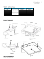
Model No. www.theiowafoilprinter.com Rev. A M100 & M100-HV M20 & M20-HV M24 & M24-HV The Iowa Foil Printer User’s Manual Contents: Safety Instructions …………………………….. 2 General Information ………..……………….. 2 System Components ……....................... 3 Technical Data ………………………….………. 3 Ground & Extension Cord Information . 4 System Setup….…………………………………… 4 Using Digital Controls.………………………… 5 Foil Roll Information ………………………….. 6 Printer Positions ………………………………… 6 Loading Printer dispenser ………………….. 7 Operating Printer & Hot Plate ……………. 8 Care & Maintenance ………………………….. 8 Printing with dispenser ……………………… 9 Trouble Shooting ……………………………….. 10 Warranty …………………………………………… 10 Model 100 wiring diagram ………………… 11 Model 20 & 24 wiring diagram ………….. 12 U.S. Patent No. 5,013,386 Listed No. 2S85 The Iowa Foil Printer 2 Foil Printer System User’s Manual Safety Instructions READ THIS MANUAL BEFORE USING THE IOWA FOIL PRINTER (IFP) FOIL PRINTER SYSTEM. This device is electrically powered and must be operated in a safe environment to avoid risk of fire, explosion, or electric shock. Statement s CAUTION! Statements that identify conditions or practices that could result in damage to the equipment or other property. WARNING! Statements that identify conditions or practices that could result in personal injuries or loss of life. Symbols HOT SURFACE Heating surfaces of foil printing system will be very hot during operation. SHARP EDGES Razor blades used on the foil cutter are extremely sharp. Serious injury can occur. General Information WARNING! NO USER SERVICEABLE COMPONENTS INSIDE The IFP model 100 hand roller contains no user-serviceable parts. Contact The Iowa Foil Printer sales and service representative for service. WARNING! DO NOT EXPOSE THE FOIL PRINTING EQUIPMENT TO MOISTURE. NOT ALL SYSTEM COMPONENTS ARE WATER RESISTANT. Product Covered IFP Printer Models 100 and IFP Hot Plate Model 20 and 24. Description of Use The Iowa Foil Printer (IFP) Printer is used in conjunction with the IFP Hot Plate to stamp foil onto another substrate such as paper. The Printer has a heated roller, foil dispenser, and foil cutter. The Hot Plate has a square heated aluminum plate, a printer resting pad, foil hold down strip, and large wood surface for additional substrate support. The Iowa Foil Printer Foil Printer System User’s Manual Table 1: Technical Data: Ordering Number M20 M24 M100 M20-HV M24-HV M100-HV Power Requirements 115 V (ac) +10%, - 15% 50/60 Hz +/- 5% 230 V (ac) +10%, -15% 50/60 Hz +/- 5% Maximum Power 600 Watts 900 Watts 200 Watts 800 Watts 1200 Watts 200 Watts Maximum Current 5.2 Amps 7.8 Amps 1.7 Amps 3.5 Amps 5.2 Amps 0.9 Amps System Components 4X Air Gap Hot Plate Printer Controls & Display Wood Frame Roller Spring Loaded Spindle Figure 1 Printer Rest Metal Strip Controls & Display Power Cord Figure 2 Spindle 2X Handle Power Inlet Module 3X Vent Cutter Figure 3 The Iowa Foil Printer Power Cord Cooling Fan Figure 4 3 4 Foil Printer System User’s Manual Ground and Extension Cord Information The foil printing system MUST be grounded against electrical shock. It is equipped with a three-wire conductor and three-prong plug to fit a grounded receptacle. NEVER CONNECT THE GREEN OR GRENN/YELLOW WIRE TO A LIVE TERMINAL! Use only three-wire extension cords that have three-prong, grounding-type plugs and three-pole receptacles. The extension cord wire size must meet be rated to handle the power requirements as given in the Table 1. System Setup WARNING! HOT SURFACE Surface of Hot Plate & Roller will be hot. Do not touch their surfaces. CAUTION! It is important for proper cooling to ensure that nothing blocks the air flow to the three vents, the Air Gap between the heated metal Hot Plate and Wood Frame, and the Fan on the underside of the Hot Plate. . 1. Select an appropriate location that is clean, well lit, well ventilated, and away from flammable fumes and materials. 2. Set the hot plate on a flat and stable surface. 3. Plug the un-pronged end of the power cored into the inlet power module on rear side of the hot plate. Plug the pronged end into a power source appropriate for the voltage of system. See Figure 4. 4. Turn on the system using switch on the inlet power module. See Figure 4. 5. Set the desired hot plate temperature on the control panel. How to use the operational controls are explained in Figures 5 & 6. 6. Set the printer on the printer rest of the hot plate in the printer rest position shown in Figure 7. 7. Plug the printer into a power source appropriate for the voltage of system. 8. Wait for the set temperature to be reached indicated by when the load light turns off. See Table 2 for approximate warm-up times. Table 2: Approximate heating times (min)* Set Temperature 110°F/43°C 140°F/60°C 170°F/77°C 200°F/93°C 230°F/110°C 160°F/127°C Model 100 1 2 3 4 5 6 Model 20 5 8 13 17 23 30 Model 24 5 9 15 20 27 35 * These guidelines are based on use of a thermal plate cover and a starting temperature of 70 deg F. Heating times will be longer without a thermal plate cover. ** Temperatures above 230 deg. F are depend on the operational variables and may require use of a insulating thermal plate cover. The Iowa Foil Printer Foil Printer System User’s Manual Using Digital Controls Figure 5 Figure 6 To set the temperature units on models with tactile keys, first hold down both the Increment and Decrement keys for ten seconds. The display will show “F C” for two seconds. Adjust the units with the Increment and Decrement keys. The new value will tank effect three seconds after the last key stroke. The display will blink, then return to the primary display after the five seconds. The set point value will automatically adjust to the new temperature scale. The units on models with a set point knob cannot be changed. See Figures 1 & 2. To adjust the Calibration Offset on models with tactile keys, first hold down both the Increment and Decrement keys for five seconds. The display will fist show “CAL” for five seconds, then it will display the Calibration Offset value. Adjust the value with the Increment and Decrement keys (range: -30 to 30). The new value will take effect three seconds after the last key stroke. The display will blink, then return to the primary display after five seconds. The Offset on models with a set point knob cannot be changed. See Figures 1 & 2. The Iowa Foil Printer 5 6 Foil Printer System User’s Manual SETUP Foil Roll Information The Iowa Foil Printer Model 100 has an integrated foil dispenser that is designed to hold a 6 inch wide roll of foil. To fit in the IFP M100 the rolls of foil must meet the following criteria: Maximum roll diameter: 2.0 inches (25 mm) equivalent to 100 to 200 feet (30 to 60 m) of foil depending on the type of foil. Different foils have a different thickness. Roll length specifications: 6.0 +/- 0.125 inches (152.4 +/- 3.2 mm) Printer Positions CAUTION! It is important to ensure that nothing is in contact with the roller during storage or else permanent damage to the roller surface could occur. Threading position: This position is best for loading the dispenser and threading the foil through dowel pins. Printing position: This position is used for printing where only the roller should be in contact with hot plate. Resting position: This position is the most commonly used operational resting position and can be placed on the Hot Plate Rest. Storage position: This position, where the digital readout faces up, has the maximum stability and should be used whenever the printer is not in use. (The printer may be positioned with the digital readout facing down for loading and threading the dispenser.) Threading Position Printing Position Resting Position Storage Position Figure 7 Note: Power cord side of the printer face shown in all positions. The Iowa Foil Printer Foil Printer System User’s Manual Loading Printer Dispenser Foil Color Side WARNING! HOT SURFACE Surface of Roller can be hot. Do not touch their surfaces. WARNING! SHARP EDGES Razor blade on cutter is extremely sharp. 1. Place IFP in Storage Position shown in Figure 7. Position roll so adhesive side will be facing up as shown in Figure 9. Place one end of roll on two spindles by first placing one end of roll on spring loaded spindle. While pushing in spindle inserting roll onto other spindle and release. Make sure roll leaf is centered on spindles by spinning it and gently trying to dislodge roll from spindles. 2. Place IFP in Threading Position shown in Figure 7. Place Floating Dowel in Threading Position as shown in Figure 10. 3. Thread Leaf over first two Fixed Dowels, under Floating Dowel, and over fourth Fixed Dowel as shown in Figure 9. Pull about 4 inches or 10cm of Leaf Beyond the last dowel. 4. Using two handles pick printer up and tip top back toward operator until floating pin drops down into Printing Position shown in Figure 7. Foil Adhesive Side 4X Fixed Dowel Cutter Heated Roller Adhesive Side Figure 9 Floating Dowel in Threading Position Razor Blade Floating Dowel Printing Position Figure 10 The Iowa Foil Printer 7 8 Foil Printer System User’s Manual Operating the Printer & Hot Plate: WARNING! HOT SURFACE Surface of Hot Plate & Roller will be hot. Do not touch their surfaces. 1. With the printer in the resting position, plug the power cord into an outlet, and set desired stamping temperature. 2. When the desired stamping temperature is reached on the Printer and the hot plate, place paper or other substrate on the hot plate and position the roll leaf to be stamped. Roll leaf may be arranged on paper before placing it on hot plate. 3. With the digital readout facing you lift the printer by both handles and set it down on the paper and foil in the upright Printing Position. While maintaining contact with the hot plate, carefully rock the printer back and forth to ensure the roller moves easily without dragging. Roller action should be very smooth. If any dragging is experienced, it indicates that printer is being tilted too far backward or forward. 4. Push the printer away from your body, bringing downward pressure to bear on the substrate. 5. Roll the printer slowly back and forth until roll leaf adheres firmly to the substrate. 6. Set the printer down in resting position on the rest plate. 7. Pick up the print off of the hot plate and cool it in air by gently waving it back and forth. 8. Lift and slowly peel the polyester film off the print. Switch (On Position) Power Cord Figure 8 Care & Maintenance: WARNING! HOT SURFACE Surface of Hot Plate & Roller will be hot. Do not attempt to clean the Hot Plate or Printer while they are hot or plugged into a power source. The Printer and Hot Plate are designed to be maintenance free for the life of the product. It is normal for adhesive residue to build up on the roller and hot plate heating surfaces. Both surfaces can be cleaned with Isopropyl Alcohol (Rubbing Alcohol) at a concentration of 91% or greater. The Iowa Foil Printer Foil Printer System User’s Manual 9 Printing With Dispenser WARNING! HOT SURFACE Surface of Hot Plate & Roller will be hot. Do not touch their surfaces. 1. Lift the printer up and all in one motion push printer forward in air to create enough draft to push Leaf under heated roller. Immediately set the printer down onto the work piece with the Leaf under the heated roller in the Printing Position as shown in Figure 3. 2. (Optional) Use the magnetic strip or magnetic pins to hold down the loose end of the Leaf to metal strip located near the edge of hot plate. See Figure 10. 3. Leaf will be dispensed and stamped onto work piece as printer is pushed forward. Perform a test sample before applying to an actual work piece. Magnet Strip Magnet Pin Metal Strip WARNING! SHARP EDGES Razor blade on cutter is extremely sharp. Figure 10 4. Cut the foil at the end of the dispensing motion. While keeping the foil taut pinch the white handle of cutter between your thumb and index finger and slide the cutter across to the opposite side of printer. See Figure 11. Replacing Cutter Blade Knob (Pinch) WARNING! SHARP EDGES Razor blade on cutter is extremely sharp. 1. 2. 3. 4. Place IFP in Service Position shown in Figure 7. Loosen the knob by turning it counter clockwise. See Figure 11. Using a small needle nose pliers pull the blade out from the mandrel. Using needle nose pliers push a new blade back into the mandrel. Be certain that it is fully seated. The tip of the blade should not stick much beyond the lower dowel shown in Figure 11. 5. Tighten the knob back to finger tight. Test that the cutter still slides smoothly and that it cuts correctly. Mandrel Blade (Pinch) Figure 11 The Iowa Foil Printer 10 Foil Printer System User’s Manual Troubleshooting Indication The display is not illuminated. Probable Cause(s) Corrective Action • Power supply switch off. • Power cord not plugged into outlet. • Turn switch on. • Replace fuse (check cause of failure). • Ensure cord end is pushed firmly into inlet module. • Verify input power. • Repair or replace controller. • Power supply cord on full plugged into inlet module. • Power supply voltage incorrect. • Defective controller. Foil from the dispenser has wrinkles after printing onto substrate. • Foil roll not centered on spindles. • Check to make sure core of foil roll is not damaged. • Center the roll on the spindles and revolve a few times to ensure it runs without wobbling. Cutter will not cut foil from dispenser • Blade is dull. • Blade is installed incorrectly. • Replace Blade. • Ensure blade is fully seated and the tip rests flat on dowel. Hot Plate will not hold temperature above 220°𝐹 (105°𝐶) • Thermal insulation cover is required in most cases to maintain higher temperatures. • Hot Plate overheated . • Use insulation blanket. • Wait for unit to cool down (check cause of failure). IFP Limited Lifetime Warranty IFP hereby warrants to the purchaser of this product that the nonelectrical components of the product shall be free from defects in material and workmanship for the life of the product. All electrical components installed in or on the product are warranted to be free from defects in material and workmanship for three years from the date of purchase. The purchaser’s remedies shall be limited to replacement and installation of any parts that fail through a defect in material or workmanship. IFP specifically disavows any other representation, express or implied, warranty, or liability relating to the condition of use of the product, and in no event shall IFP be liable to purchaser, or any third party, for any direct or indirect consequential or incidental damages. The Iowa Foil Printer Foil Printer System User’s Manual The Iowa Foil Printer 11 12 Foil Printer System User’s Manual The Iowa Foil Printer