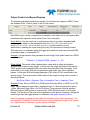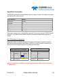
1
BOA
Smart Vision System
Version 06
teledynedalsa.com/ipd
INSTALLATION MANUAL
1
Version 06
Notice
BOA Vision System Installation Manual
Document Number 405-00025-00
Revision: 06
Copyright 2011 Teledyne DALSA Corporation.
All rights reserved.
All copyrights in this manual, and the hardware and software described in it, are the
exclusive property of Teledyne DALSA Corporation and its licensors.
Claim of copyright does not imply waiver of Teledyne DALSA Corporation or its
licensors other rights in the work. See the following Notice of Proprietary Rights.
NOTICE OF PROPRIETARY RIGHTS
This manual and the related hardware and software are confidential trade secrets
and the property of Teledyne DALSA Corporation and its licensors. Use,
examination, reproduction, copying, transfer and/or disclosure to others of all or
any part of this manual and the related documentation are prohibited except with
the express written consent of DALSA Corporation.
The information in this document is subject to change without notice. Teledyne
DALSA Corporation makes no representations or warranties with respect to the
contents of this manual and specifically disclaims any implied warranties of
merchantability or fitness for a particular purpose. Teledyne DALSA Corporation
assumes no responsibility for errors or omissions in this document.
iNspect, Sherlock, and the DALSA logo are trademarks of Teledyne DALSA
Corporation. All other trademarks are the property of their respective owners.
Teledyne DALSA Industrial Products
Information: [email protected]
Support: [email protected]
Web: http://www.teledynedalsa.com/ipd
700 Technology Park Drive
Billerica, MA, USA 01821
Tel 1.978.670.2002 Fax 1.978.670.2010
Version 06
teledynedalsa.com/ipd
2
Certifications
Declaration of Conformity
Manufacturer
Teledyne DALSA Corporation
605 McMurray Road
Waterloo N2V 2E9
Ontario, Canada
CE
We declare that this product has been tested to comply with the
EC Directive for a class A digital device in accordance with
EN55022/CISPR22
FCC
We declare that this product has been tested and found to
comply with the limits for a class A digital device, pursuant to
Part 15 of the FCC rules. These limits are designed to provide
reasonable protection against harmful interference in a
residential installation.
This equipment generates, uses and can radiate radio
frequency energy and may cause harmful interference to radio
communication.
Other
IP67
This product meets the requirements for industrial applications
that require IP67 wash down protection - requires fitted sealing
lens cover and sealing plugs on unused connectors
CFR 21 Part 11
This product provides the tools needed for users to implement
an auditing program that could be in compliance with CFR 21
Part 11. These tools include:
• System or software backup and restore
• System software security (password login and access limits)
• Protection of system backup files from modification.
• Record of actions by users with time stamp information
• Time stamp information on data output.
Version 06
teledynedalsa.com/ipd
3
Handling Precautions
Care should always be exercised when handling and operating your BOA Vision
System. Even though the system is encased within a rugged, industrial enclosure,
incorrect use or handling can result in damage to your investment. To prevent this, we
recommend you avoid the following:
•
Hot-plugging cables and devices. Be sure to shut the system down and remove
power before connecting or disconnecting anything to it.
•
Free-standing operation. It is advisable to mount the system properly to prevent it
from falling accidentally. Mounting holes are provided on each side of the system.
•
Operating the system in an environment outside of it’s recommended operating
conditions.
Electro Static Discharge
Avoid the damage that ESD can cause. Never expose the internal electronics to a
potentially hazardous environment by opening the enclosure. Doing so may cause
serious damage.
User Service Warning
This product has no field-replaceable components. Tampering with the unit will void the
product warranty.
Warranty
Teledyne DALSA warrants the BOA Vision System against defects in materials and
workmanship for a period of twenty four (24) months from the date of delivery. DALSA
and its representatives expressly disclaim any and all other warranties.
Your sole remedy shall be repair or replacement of the BOA Vision System product and
associated optional components, provided that the defective product is returned within
the warranty period.
If you need to return the BOA Vision System, you must contact the Teledyne DALSA
representative who sold you the product. Do not return your product to Teledyne DALSA
without prior authorization.
Teledyne DALSA assumes no liability for damages resulting from the use of this manual.
Version 06
teledynedalsa.com/ipd
4
Table Of Contents
Introduction
Installation
Software
Specifications
Version 06
BOA Vision System
……………………...............................
6
Product Support
……………………...............................
6
Components
……………………...............................
7
Connections
……………………...............................
8
Cable Pinouts
……………………...............................
9
Cable Configurations
……………………...............................
10
Panel Link Module
……………………...............................
10
Ethernet Only Setup
……………………...............................
11
Ethernet and I/O Setup
……………………...............................
12
Getting Started
……………………...............................
13
iDiscover Utility
……………………...............................
14
BOA Web Server
……………………...............................
15
Firmware Updating
……………………...............................
16
The BOA Emulator
…………………………………………..
17
General Specifications
……………………...............................
18
Input Specifications
……………………...............................
19
Output Specifications
……………………...............................
20
Output Control
…………………………………………..
21
Panel Link Specification
……………………………………….....
22
Panel link Wiring
…………………………………………..
23
Serial Port Connection
…………………………………………..
24
BOA Mechanicals
……………………...............................
25
PL-100 Mechanicals
……………………...............................
26
teledynedalsa.com/ipd
5
Introduction
BOA Vision System Overview
BOA is a fully integrated vision system in a compact “smart” camera format that has
been specifically designed for industrial use. Packaged complete with application
software embedded, BOA provides an easy-to-deploy automated inspection system for
the factory floor.
BOA vision systems are configured and monitored remotely using an Ethernet
connection to a PC or factory network. An inspection can be quickly setup using a web
browser portal into the resident iNspect application. The software interface is fully
equipped with a suite of vision tools and capabilities that satisfy a range of inspection
needs, from positioning, identification and measuring, to verification and flaw detection.
BOA vision systems are small, rugged devices that can be easily integrated into
existing production lines, machinery or moving equipment. They are supported by
standard industrial M12 cordsets to further simplify and reduce implementation costs.
Rated for IP67 deployment when fitted with a compatible lens cover, BOA systems can
be mounted in wash down factory environments without the need for additional
protective enclosures.
For a complete list of specifications, refer to “Specifications” on page 18.
Product Support
In addition to this installation manual, the following information ships with the product:
1.
2.
3.
4.
5.
Online help: Fingertip help is available on every screen (panel) of the iNspect User
Interface
The iNspect User Manual is included on the CD that ships with the product
Self help material and sample job files are included on the CD
Factory support is available at [email protected]
Call, fax or email your local representative who sold you the product
Version 06
teledynedalsa.com/ipd
6
BOA Vision System Components
BOA vision systems are shipped with the components listed below. Take a few
moments to verify that everything has arrived in good condition. If your product has
been visibly damaged during shipment or is missing parts, please contact your
Teledyne DALSA representative immediately.
Standard components (ship with every BOA Vision System):
Component
Description
BOA Vision System
BVS-0640M-INS OR
BVS-0640C-INS OR
BVS-1024M-INS OR
BVS-1280M-INS
BOA Vision System. Fully integrated vision system with
640x480 mono or color sensor, processing engine, iNspect
embedded software, communications and light control.
BVS-INS-CD
CD including PC emulation software and associated product
manuals.
Mounting Screw Kit
M4 screws for mounting the sensor (Qty 4)
Optional components (sold separately):
Component
Description
Cables
A-BVS-E8S-X
A-BVS-IO8S-X
A-BVS-L5S-X
M12-RJ45 Ethernet cordset (X; 5=5m, 10=10m)
M12 single-ended IO cordset (X ;5=5m, 10=10m)
M12 single-ended lamp cordset (X; 2=2m, 5=5m)
BVS-PL-100
Panel Link breakout module. Provides Ethernet power and
convenient panel access to BOA I/O
A-MB-BVS-0
Right Angle mounting block with 8 M4 screws
Lens
Various Lens options available from DALSA
A-BVS-LCG-X
Lens cover for BOA Vision System. Required for IP67
compliance. (x=35, 40 or 45 mm internal lens length)
A-BVS-LSS-F
A-BVS-M12-P
Set screws for Fujinon Lens
M12 plug for IP67 compliance
Lights
Various Lighting options available from DALSA
Version 06
teledynedalsa.com/ipd
7
Installation
Connecting the BOA Vision System
This section details how to connect the BOA vision system with its associated
components and factory environment.
Camera Connectors and Indicators
Designator
Definitions
LAN
10/100 BaseT Ethernet connection. Provides the primary
interface for configuring the camera, developing the application
and monitoring results.
NOTE: The camera can be powered from the Ethernet cable
directly (Passive Power over Ethernet)
I/O PWR
Provides access to the camera I/O – 2 IN, 2 OUT Opto. Also
provides PWR input (12-30V).
LAMP
Provides PWR and strobe control to a local LED light source.
NOTE: Lamp PWR is identical to BOA PWR input. The camera
should be powered from a 12V PWR source if the light requires
a 12V supply (Recommend 24V supply)
LAN LED
Red/Green/Yellow = Network activity
Blue = Warm Reset
LED2
Green = Inspection Pass (runtime)
Blue blink = Booting (should stop after 20 seconds)
Blue = Inspection Recycle (runtime);
Red = Inspection Fail (Runtime)
LED1
Blue Solid = Camera booted, not configured
Green blink = Solution loaded, acquisition in process
Green Solid = Solution loaded
Red = Camera Fault
Version 06
teledynedalsa.com/ipd
8
Cable Pinouts
The BOA vision system is compatible with M12 factory cordsets as show below:
LAN Connector Pinout and Cordset
Pin
Name
RJ45 Pin
1
PWR *
5
2
NC
7
3
GND *
8
4
TXD-
2
5
RXD+
3
6
TXD+
1
7
NC
4
8
RXD-
6
A-CAB-BVS-E8S-X
I/O-PWR Connector Pinout and Cordset
Pin
Name
Color
1
TRIG
White
2
PWR
Brown
3
IN0
Green
4
OUT1
Yellow
5
IN CMN
Grey
6
OUT0
Pink
7
GND
Blue
8
OUT CMN
Red
A-CAB-BVS-IO8S-X
LAMP Connector Pinout
Pin
Name
Color
1
PWR
Brown
2
RS232 RX
White
3
GND
Blue
4
STR
Black
5
RS232 TX
Yellow
A-CAB-BVS-L5S-X
* For Passive Power over Ethernet
Version 06
teledynedalsa.com/ipd
9
Cable Configurations
The BOA vision system offers flexible cabling options to suit a number of application
configurations:
1.
For single cable applications, the Ethernet cable can be used to supply power
(referred to as “Passive Power over Ethernet”) and communications between the
camera and the control environment. Power is supplied by connecting a DC voltage
source between 12-30V to conductors 4 (pwr) and 8 (gnd) on the Ethernet RJ45
connector. Note: The PL-100 module does this automatically. In this configuration,
the camera I/O is unavailable.
2.
For single cable applications that do not require a runtime Ethernet connection, the
I/O-PWR cable provides limited communications and power between the camera
and the control environment. Note: Ethernet is still required for setup.
3.
For typical applications, both the Ethernet and I/O-PWR cables are connected to
provide flexibility between the camera and the control environment. In this
configuration, either or both cables can supply power provided they come from the
same power source. Do not connect different power sources to the BOA camera
connectors.
4.
In all configurations, the Lamp cable can be connected between the camera and a
compatible LED light source. The BOA vision system supplies power and strobe
control to the external light. Power is routed from camera power input to the lamp.
BEWARE: Connecting a voltage on pin 1 of the lamp connector that is lower than
the input power voltage to BOA could result in damage to the camera!!
Panel Link Module (A-BVS-PL-100)
The PL-100 module is an optional module that provides a safe and convenient way to
interface BOA. It provides an isolation layer between the factory and the camera
(differential isolation), as well as supplying power via the Ethernet cable for single cable
applications. The PL-100 also provides a manual trigger button and status lights for
application debug.
A-BVS-PL-100
NOTE: The BOA vision system does not support the IEEE 802.3af standard Power over
Ethernet (PoE) and should not be directly connected to a PoE supported router.
Version 06
teledynedalsa.com/ipd
10
Ethernet Only Setup with Lamp
1.
Connect the M12-8 male end of the Ethernet cordset (A-BVS-E8S-X) to the M12-8
female connector labeled “LAN” on the camera.
2.
Connect the RJ45 end of the Ethernet cordset to the RJ45 connector labeled
“CAM LAN” on the Panel Link breakout module (A-BVS-PL-100)
3.
Connect the RJ45 labeled “LAN” on the breakout module to the controlling PC,
PLC or the factory LAN
4.
Connect camera PWR and GND to the breakout screw terminals labeled “PWR”
5.
Connect the Lamp via corset A-BVS-L5S-X between the camera (M12-5 and the
lamp)
Setup Computer,
PLC or Factory
Network
A-BVS-PL-100
A-BVS-E8S-X
Cat5 Cable
BOA System
LED Lamp
Version 06
A-BVS-L5S-X
teledynedalsa.com/ipd
11
Ethernet and I/O Setup with Lamp
1.
Connect the M12-8 male end of the Ethernet cordset (A-BVS-E8S-X) to the M12-8
female connector labeled “LAN” on the camera.
2.
Connect the RJ45 end of the Ethernet cordset to the RJ45 connector labeled
“CAM LAN” on the Panel Link breakout module (A-BVS-PL-100)
3.
Connect the RJ45 labeled “LAN” on the breakout module to the controlling PC,
PLC or the factory LAN
4.
Connect camera PWR, GND and I/O from the control panel to the breakout screw
terminals.
5.
Connect the M12-8 male end of the IO-PWR cordset (A-BVS-IO8S-X) to the M128 female connector on the camera labeled “I/O PWR”
6.
Connect the open-ended wires of the IO-PWR cordset to their respective
connections on the breakout module.
Setup Computer, PLC
or Factory Network
A-BVS-PL-100
A-BVS-E8S-X
A-BVS-IO8S-X
Cat5 Cable
BOA System
LED Lamp
A-BVS-L5S-X
Version 06
teledynedalsa.com/ipd
12
Software Interface
Getting Started
The BOA vision system is supplied with the iNspect vision application embedded. This
application offers a suite of vision capabilities to satisfy a diverse range of automated
inspection needs. The application interface is accessed through the Ethernet
connection using a PC with Microsoft Internet Explorer 6 or higher. You do not need to
install software on your host system to setup or operate the BOA system.
Take note of the following before attempting to access the application:
1.
BOA vision systems are preconfigured with a default static IP address of
192.168.0.100
2.
The PC used to access BOA initially will need to be configured on the same
network neighborhood, but with a different address (i.e. 192.168.0.101). Consult
your system administrator for instructions on how to do this. The subnet mask
should be set automatically to 255.255.255.0
3.
This static IP address can be changed at any time through the BOA web server
interface to match your Local Area Network. Click on the “Setup Device” hot link to
change the network address. Remember to keep a record of what the new
address is set to. BOA supports both DHCP and Static IP addressing (preferred
since the address does not change).
NOTE: A power cycle is required before the new address will take effect.
4.
If you incorrectly set, or forgot, the new address of your BOA, you can run the
“iDiscover” utility. This program is installed automatically when you click on the
“iNspect Express” or “upgrade” hot links in the web server interface. This program
is also on the iNspect emulator CD that ships with the system.
5.
In most cases you will need administrator privileges on your PC to access BOA. It
may be necessary to customize the security settings on your browser to download
and run ActiveX controls.
6.
If for any reason you can not access BOA from your internet browser, you can
install the emulator application from the shipping CD and connect to the camera
through this interface. This step is explained in more detail later in the manual.
7.
BOA is compatible with host computers running the Windows XP operating
system. BOA has also been verified on the new Windows 7 O/S.
NOTE: See document on CD “Configuring Windows for BOA”
Version 06
teledynedalsa.com/ipd
13
iDiscover Utility
The iDiscover utility is provided for discovering BOA cameras connected to the local PC
network. iDiscover is installed on the host system when a BOA camera is first
connected. It is also installed as part of the emulator installation.
The iDiscover program can be launched in one of two ways:
1.
If the connecting PC has previously been used to interface a BOA camera, then
the iDiscover program resides in the windows System32 directory. To invoke, open
the command prompt (“Start programs -> Run”), type “iDiscover” and click “OK”
2.
If the connecting PC has not previously been used to interface a BOA camera, you
must first install the iNspect software emulator. Once installed, the program can be
invoked from the iDiscover shortcut (“Start programs -> IPD iNspect -> Discover
BOA Cameras”).
Once launched the GUI below will be shown. The left panel shows the MAC addresses
of all reachable BOA cameras. Click on one of these to populate the associated
network configuration on the right. You can then modify the BOA IP address (click
“Apply”) or connect to the associated camera (click “Connect To Device”).
Version 06
teledynedalsa.com/ipd
14
BOA Web Server
The BOA web server is a portal through which the BOA system can be set up and
configured for an application. The web server is accessed from a host PC using
Microsoft Internet Explorer version 6 or higher as follows:
1.
Open Internet Explorer on the configured PC connected to the camera
2.
Enter the URL address of the camera: 192.168.0.100 and click “go”
3.
The camera web server interface will be displayed in the browser as follows:
4.
The web server provides a quick snapshot of the state of the camera and provides
controls for language selection, IP address setup, firmware upgrading and image
backup or restore. The web server is the portal into the inspect application and can
be set up to prevent unauthorized access.
5.
Click on the “iNspect Express” hot link to launch the application. The camera will
automatically install some software components on the host PC when it connects
for the first time. These components set up the remote access to the device.
6.
Using the iNspect software (refer to the iNspect Express users manual), set up
an application and store the solution on the camera. Exit the application and return
to the web server interface.
7.
The “History Log” hot link offers a quick and convenient way to view and store
inspection results to an Excel spreadsheet on your host PC. This feature is also
available from within the iNspect application using the scripting tool.
Version 06
teledynedalsa.com/ipd
15
When the application is set up and stored on the camera, the Ethernet connection can
be disconnected and the inspection will run autonomously.
The camera can easily store over 500 solutions in its flash storage memory. These
solutions can be switched through network commands, or through established PLC
register connections or through the iNspect application interface.
The camera administrator can setup user accounts with various levels of access
privilege. With password control enabled, the web server will prompt users for a valid
login and the application will only expose controls associated with that account.
Firmware Upgrading
BOA firmware may need to be updated occasionally to add new features or fix reported
problems. To do this, click on the “Upgrade Device” hotlink to launch the upgrade
control. To upgrade, simply browse to the location of the upgrade binary file (obtain
from your DALSA representative) on the connected PC and click the upgrade button.
Note: Export your saved solution files before upgrading the firmware.
The upgrade control also supports backup and restore of the entire camera image. This
is useful for safekeeping and camera replication. We highly recommend exporting
solutions after any modification.
After a firmware upgrade, it is recommended that the connecting PC be “cleaned” of old
or stale components associated with the previous firmware. To do this, go to the
windows command prompt and enter the “iAssistant” and click go. When the application
launches, click the “Clean” button.
Version 06
teledynedalsa.com/ipd
16
The BOA Emulator
BOA is shipped with a full-featured emulator that allows you to prepare or debug
solutions offline. The emulator is available on the CD that ships with the camera and is
very easy to install (load CD into your CD drive and follow the installation wizard). A
users manual for the emulator is included on the CD.
The emulator installation offers an alternate way to access the BOA camera for users
who do not wish to use the standard web browser interface. After the installation is
complete, the following related shortcuts will be available:
Windows Start -> All Programs -> DALSA-IPD iNspect Express ->
Emulator Access
BOA Access
Start output logging
Connect not using browser
Launch iDiscover program
Launch iDisplay App
Launch Online Help
Launch Emulator
Generate report on
selected solution (browse
to select)
Upgrade a single camera
Upgrade multiple cameras
Note 1: When you access BOA through this interface, it is important that you maintain
version compatibility between the camera and the emulator.
Note 2: Some shortcuts and programs are only available with versions 1700 or above
Version 06
teledynedalsa.com/ipd
17
Specifications
General Specifications
This following table lists the specifications of the BOA vision system:
Specification
Definition
Memory
Storage
256 MB Storage; 256MB Program
Image
Sensor
1/3 inch CCD; 7.4 μm pixel size
Resolution
640x480
Type
Mono or Color Progressive Scan
Exposure
22 us to 1000 ms
Acquisition
Async Reset, full-frame integration, 60f/s (application dependent)
Lens
C Mount
Trigger
1 opto-isolated hardware trigger input
I/O
Software trigger via Ethernet or internal timer
Inputs
1 General purpose opto-isolated.
Expandable via Ethernet I/O module
Outputs
2 General purpose opto-isolated
Expandable via Ethernet I/O module
Strobe
1 dedicated strobe output for LED light source
Status
Network + 2 application assigned LEDs
Network
Ethernet
10/100 BaseT
Serial
RS232
1 Port – flying leads on lamp connector
Power
12-30V
Via Ethernet or IO connectors (not PoE compliant)
Device
150 mA maximum @ 24V (3.6 Watts)
Lamp
1A maximum (BOA powering light source directly)
Material
Machined Aluminum with anodize/paint finish
Mounting
8 x M4 plus optional mounting block
Size
44mm x 44mm x 56mm (without lens cover)
Temp
-10°C (14°F) to 50°C (122°F) Operating (-60°C to 80°C) Storage
Protection
IP67 with cables attached
Shock
70 G
Mechanical
Environment
Certification
Version 06
FCC Class A and EU CE
teledynedalsa.com/ipd
18
Input Specifications
The BOA vision system provides two dedicated opto-isolated, polarity independent
inputs. One of the inputs provides the acquisition Trigger function, while the other is
general purpose.
Specification
Voltage
Definition
ON
12-30 V
OFF
0-3 V (12 V nominal threshold)
Current
ON
7.5 mA typ (24 V applied)
Protection
Resistance
3K Ohms
Isolation
4000 V RMS
Common pin
Input
PWR or GND
Switch Time
ON
10 Microsecond
OFF
50 Microseconds
Trigger
62 Microseconds from trigger input to start of acquisition
Latency
The active polarity of each input is configured in the iNspect application. The camera
includes a noise filter on the input which is also configurable.
To connect with an NPN source, connect the camera trigger input (pin 1) to the NPN
source output and the camera common input (pin 5) to PWR. When the source output
turns ON, the camera input will be pulled down turning the opto-coupler ON.
To connect with an PNP source, connect the camera trigger input (pin 1) to the PNP
source output and the camera common input (pin 5) to GND. When the source output
turns ON, the camera input will be pulled up turning the opto-coupler ON.
Input Diagram
NPN Wiring
Version 06
teledynedalsa.com/ipd
PNP Wiring
19
Output Specifications
The BOA vision system provides two dedicated opto-isolated, solid state relay outputs
and a separate dedicated light strobe (pin 2 of lamp connector).
Specification
Definition
Voltage (Vin)
Load
24V maximum
Current
GPO[0:1]
100mA max (drives to OCMN when active)
STRB
100mA max (drives to Vin when active)
NOTE: Strobe timing selected in iNspect Sensor Panel
Protection
Fuse
PTC fuses to 100mA (GPO) & 100mA (STRB)
Common pin
Out
PWR or GND
Switch Time
ON
10 Microsecond
OFF
50 Microseconds
The active polarity of each output is configured in the iNspect application as detailed on
the following page.
To connect with an NPN input source, connect the camera output (pin 4 or 6) to the
NPN source input and the camera common output (pin 8) to GND. When the camera
output turns ON, the opto switch closes and OUTX = 0 (current flows through load)
To connect with an PNP input source, connect the camera output (pin 4 or 6) to the
PNP source input and the camera common output (pin 8) to PWR. When the camera
output turns ON, the opto switch closes and OUTX = output common.
Output Diagram
Version 06
teledynedalsa.com/ipd
20
Output Control via iNspect Express
The iNspect application provides two options for controlling the outputs on BOA. These
are selected in the “Control” panel of the GUI as shown:
Each BOA output can be configured by an equation in the script tool or a programmable
pulse based the inspection result (either Pass, Fail or Recycle):
Script Setting: Use the script tool to configure an output to provide a programmable
level or a pulse based on the application need (Note: the GUI pulse settings are
disabled in this mode – shown as dark gray above). Script selection is nondeterministic, meaning the output timing may vary if the processor is heavily loaded.
This may occur, for example, when the trigger and inspection times are close and BOA
is serving images to a connected PC.
Example: A script equation that generates an active high 10ms pulse based on a PASS
result would be:
If (Result = 1) Global.GPO[0] = pulse( 1, 0 , 10)
Pulse Setting: This mode offers a deterministic output with an offset and duration
synchronized to the incoming trigger. In this mode, the output will pulse IF the result is
TRUE and the total inspection time is less than the pulse offset from the trigger. If the
pulse offset is too short, BOA will not generate a pass pulse even if the inspection
passes. In this case, BOA will always generate a FAIL pulse if FAIL is selected on the
second output. This would result in false rejects if the output is being used to control a
directional device.
Min Pulse Offset = Exposure Time + Acquisition Time + Inspection Time
Example: Pulse 10ms on GPO0 for a PASS result OR pulse 30ms on GPO1 for a FAIL
result. Sensor exposure time is 9ms, acquisition time is ~16ms and inspection time is
~35ms. Minimum Pulse Offset = 9+16+35=60ms. IF the minimum offset is satisfied,
BOA will output a PASS pulse on a good result, ELSE BOA will output a FAIL pulse
instead. The duration of the pulse is not significant in this decision. However, setting the
pulse longer than the trigger period is not advised. Max pulse duration is 64ms.
Note: Processing overhead can also affect the minimum pulse offset requirement. It is
good practice to calibrate this time based on your typical expected usage of the system
(i.e. inspection time overhead + system access overhead)
Version 06
teledynedalsa.com/ipd
21
Panel Link Specifications
The PL-100 module offers additional isolation for the BOA camera and simplifies wiring
at the control panel. The module also provides power over Ethernet for single cable
applications.
I/O connections to the BOA camera should be wired to the TOP connectors on the PL100 (J2 and J3) directly. NOTE: Avoid reversing PWR/GND on the I/O connector. Doing
so may make the PoE feature unusable. In this case power must always be supplied
through the IO cable.
I/O connections in the control panel (outside word) should be wired to the BOTTOM
connectors on the PL-100 (J5 and J6). Specification for these signals are as follows:
Specification
Definition
Voltage
Load
24V maximum
Current
GPO[0:1]
100mA max
Protection
Fuse
PTC fuses to 100mA (GPO)
Common
ICMN/OCMN
PWR or GND as wired on respective OPTOs
Switch Time
GPO[0:1]
100 Microsecond (ON or OFF)
PL-100 Connections
Ethernet
connection to BOA
I/O connections to
BOA (A-BVS-IO8)
Manual Trigger for
debugging
I/O connections to
control panel
Ethernet
connection to PC
Version 06
teledynedalsa.com/ipd
22
Panel Link Wiring Illustration
Note: BOA side is a 1:1 connection using A-BVS-IO8
24V
GND
TRG
ICMN
IN0
PL Ethernet ports not
shown
24V
GND
TRG
ICMN
IN0
ERTH
To BOA
24V
GND
NC
OUT0
OCMN OUT1
OUT1
OCMN
PL-100
OUT0
IN0TRGGND
24V
24V
To Control Panel
GND
OU0+
TRG+
OU0-
TRG-
OU1+
IN0+
OU1-
IN0-
NC
ERTH
OUT0OUT1Note: Cable color code on panel side is user defined.
Version 06
teledynedalsa.com/ipd
23
Serial Port Connection
The RS-232 serial port is accessible through the Lamp connector. By default, the serial
port settings are set as follows:
Port definition
Setting
Baud Rate
115200
Data Bits
8
Parity
None
Stop Bits
1
Flow Control
None
These port settings can be changed through the GUI by configuring the “RS232 Stream
Settings” in the Setup Control panel. Refer to the iNspect Express user manual for
details.
RS-232 Hardware Configuration
Electrically, three (3) signals are required to make a serial port connection between
BOA and another device as shown below. RS232 is a “point-to-point” connection, so
the Receive and Transmit lines must be crossed in the cable.
BOA LAMP M12-5 Connector
3rd Party DSUB-9 Connector
Pin
Name
Pin
Name
2
RS232 RX
White
3
TX
3
GND
Blue
5
GND
5
RS232 TX
Yellow
2
RX
1,4
Not required
1,4,6,7,8,9
Not required
Color
Note: It is important to establish a common ground between BOA and the connecting
3rd party device.
Version 06
teledynedalsa.com/ipd
24
BOA Mechanical Dimensions
Front View
Back View
Note: All dimensions in mm
Side View
Bottom View
Version 06
teledynedalsa.com/ipd
25
A-BVS-PL-100 Mechanical Dimensions
Top View
Note: All dimensions in mm
Side View
Version 06
teledynedalsa.com/ipd
26