1
RecoveryPump™
Massage System
Model 701RA
User Manual
Recovery Pump LLC
9 La Crue St. Suite 2
Concordville, PA 19331
Toll Free:
855-732-7867
L98101RA-A
RecoveryPump™ Model 701RA
Recovery Pump LLC
L98101RA-A
User Manual
RecoveryPump™ Model 701RA
Recovery Pump LLC
User Manual
Table of Contents
1. 2T
Important Safety Information ................................................................... 1 2T
2T
2. 2T
2T
RecoveryPump™ Specifications and Dimensions ................................... 3 2T
2T
3. 2T
2T
Key to Symbols ............................................................................................3 2T
2T
4. 2T
2T
Safety Features ............................................................................................4 2T
2T
5. 2T
2T
Indications for Use ......................................................................................4 2T
2T
6. 2T
2T
About RecoveryPump™.............................................................................5 2T
2T
7. 2T
2T
Components of the RecoveryPump™ System.......................................... 6 2T
2T
8. 2T
2T
How to Operate the RecoveryPump™ System ........................................ 8 2T
2T
2T
9. 2T
Maintenance and Storage.........................................................................18 2T
2T
2T
10. Troubleshooting ........................................................................................20 2T
2T
2T
2T
11. Warranty and Contact Information .......................................................21 2T
2T
2T
2T
12. EMC Manufacturer Declarations ...........................................................22 2T
2T
2T
2T
L98101RA-A
RecoveryPump™ Model 701RA
Recovery Pump LLC
User Manual
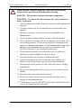
1. Important Safety Information
Read all instructions before using the RecoveryPump™ system for the first
time.
!
Warning:
! This device is intended for use by people in good health. This
device is not recommended for people who have heart problems, or
vascular problems, have a condition requiring the use of any
medical device, or have any condition that might affect their
normal well being.
! If you are, or may be, pregnant, consult with your physician before
use.
! Do not use this device over insensitive or numb areas, or in the
presence of poor circulation. Do not use if you have been
diagnosed with blood clots, deep vein thrombosis or phlebitis. This
device should not be used over swollen or inflamed areas or skin
eruptions. Do not use in the presence of unexplained calf pain.
! Consult your physician prior to use.
L98101RA-A
1
RecoveryPump™ Model 701RA
!
Recovery Pump LLC
User Manual
When using an electrical appliance, basic safety precautions
should always be followed, including the following:
DANGER - This product contains electronic components.
WARNING - To reduce the risk of burns, fire, electric shock, or
injury to persons:
1. Always unplug this product from the electrical outlet immediately
after use.
2. Use this product only for its intended use as described in this
manual.
3. Do not use with any accessories not recommended by the
Manufacturer.
4. Never use pins or other metallic fasteners with this product.
5. Never operate this product if it has a damaged cord or plug, if it is
not working properly, if it has been dropped or damaged in any
manner, or dropped into water, or if the product shows any sign of
damage or deterioration, such as cracks or worn parts. Call
Recovery Pump LLC for examination and repair.
6. Do not operate console on a soft surface such as a pillow or
mattress, or under a blanket or other covering.
7. Keep this product out of reach of children and pets.
8. Keep the equipment dry. Do not operate while bathing, in a
shower, in or around water, or in a wet or moist condition.
9. Do not reach for the product if it has fallen into water. Unplug
immediately.
10. Do not carry this product by the power cord or use the cord as a
handle.
11. Keep the cord away from heated surfaces.
12. Do not use where aerosol (spray) products are being used or
oxygen is being administered.
13. To disconnect, turn the ON/OFF switch to the OFF position, then
remove the plug from the wall outlet.
2
L98101RA-A
RecoveryPump™ Model 701RA
Recovery Pump LLC
User Manual
2. RecoveryPump™ Specifications and Dimensions
Specifications
Dimensions
Model
701RA
Height
3.9 inches
Catalog No.
L10000RA
Length
10.2 inches
Class
I
Width
5.1 inches
Pressure Range
20 - 80 mmHg
Net Weight
5.1 lb.
Voltage
115V~ 60 Hz
Power Consumption
22W
Fuses Rating
2x 2A
3. Key to Symbols
Symbol
Explanation
!
Caution! Read instructions carefully before use
On bottom of
console
Consult instructions before use
On garment label
Level of protection - type BF equipment
On bottom of
console
Temperature limitations for storage and/or
transport of the device
On carton box
Date of manufacture
On bottom of
console
2007
Accompanied by the name and the address of
the manufacturer
L98101RA-A
Location
On bottom of
console and on
garment label
3
RecoveryPump™ Model 701RA
Recovery Pump LLC
User Manual
4. Safety Features
In Case of Power Failure
If a power outage occurs during use, the RecoveryPump™ console
will deflate the air from the garments.
One-way Hose Connection
To ensure the air chambers will fill in the correct sequence, the
RecoveryPump™ has one-way connection features and color coded
connections.
The connector on the hose can be inserted into the console in one
orientation only: with the
logo facing up.
The hose end fittings (on the garment side of the hose bundle) are
color coded and are numbered from 1 to 4, indicating the order in
which they are to be connected to the matching, color coded and
numbered air inlets on the garment.
Overload Protection Fuses
The RecoveryPump™ is equipped with two overload fuses, on each
of the power lines ("~" and "0").
“Lock” Knob
The Lock knob locks the pressure adjustment knob in place,
preventing the pressure knob from being moved inadvertently.
5. Indications for Use
The RecoveryPump™ powered inflatable tube massager is indicated for
the temporary relief of minor muscle aches and pains, and for temporary
increase in circulation to the treated areas in people who are in good health.
The RecoveryPump™ simulates kneading and stroking of tissues by using
an inflatable garment.
4
L98101RA-A
RecoveryPump™ Model 701RA
Recovery Pump LLC
User Manual
6. About RecoveryPump™
RecoveryPump™ is a massage system intended for use by people in good
health. As noted above, RecoveryPump™ simulates the kneading and
stroking action of manual massage by use of an inflatable garment that fills
and deflates, applying a directional compress-and-release massage. This
soothing massage action temporarily increases circulation in the areas to
which the garment is applied, and temporarily relieves muscle aches and
pain caused by fatigue or overexertion.
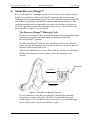
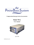
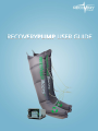
The RecoveryPump™ Massage Cycle
The RecoveryPump™ takes air from the room environment and sends
it through hoses into four individual air chambers inside the
RecoveryPump™ garment.
The RecoveryPump™ fills the four chambers with air, one after the
other, moving the massage wave up the treated area, from the base of
the leg or arm towards the torso.
After all the chambers have been filled with air, the RecoveryPump™
deflates the garment for a brief pause. Then the massage wave
repeats.
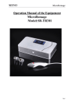
Room Air
Air cells
Room Air
Figure 1 - The RecoveryPump™ System
The air chambers in the RecoveryPump™ garment are specially
designed to overlap each other, for fluent, comfortable massage,
without gaps. You can adjust both the pressure level of the massage
and the pause time in between inflation cycles.
L98101RA-A
5
RecoveryPump™ Model 701RA
Recovery Pump LLC
User Manual
The RecoveryPump™ console can operate one or two garments
simultaneously, so you can use it on both your legs at the same time,
for a relaxing massage.
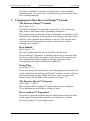
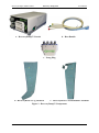
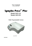
7. Components of the RecoveryPump™ System
The RecoveryPump™ Console
(See Figure 2 - a)
The RecoveryPump™ is powered by electricity. You will need to
plug it into a wall outlet with a grounding connection.
The console takes air from the room environment, and sends it to the
individual air chambers in the garment in a sequence that starts from
the base of the garment and continues to the top. The console then
vents the air from the garments, there is a brief pause, and the
massage cycle repeats.
Hose Bundle
(See Figure 2 - b)
The hose bundle transfers the air from the console to the
RecoveryBoots™ garments. It includes four hoses, a connector that
attaches to either of the air sockets on the front of the console, and
four numbered and color-coded end fittings that attach to the
corresponding air inlets on the RecoveryBoots™.
Prong Plug
(See Figure 2 - c)
If you are using only one garment, insert this plug into the unused air
outlet on the front of the RecoveryPump™ console, to seal it off and
prevent air from escaping. When not in use, store the plug in the
storage socket on the front of the console (see Figure 7).
The RecoveryBoots™ Garment
(See Figure 2 - d & e)
Each zippered RecoveryBoots™ garment has four air chambers.
These garments are available in a range of sizes.
RecoveryBoots™ Expanders
If needed, a zippered expander may be added between the two sides
of the zipper to increase the garment’s circumference. Contact
Recovery Pump LLC with requirements.
6
L98101RA-A
RecoveryPump™ Model 701RA
Recovery Pump LLC
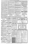
a. RecoveryPump™ Console
User Manual
b. Hose Bundle
c. Prong Plug
d. RecoveryBoots™ Leg Garment
e. RecoveryBoots™ Arm/Shoulder Garment
Figure 2 - RecoveryPump™ Components
L98101RA-A
7
RecoveryPump™ Model 701RA
Recovery Pump LLC
User Manual
8. How to Operate the RecoveryPump™ System
Step 1: Set up the RecoveryPump™ Console
a. Place the RecoveryPump™ on a flat table surface or suspend it on
the end of a bed with the attached hooks.
You should be able to reach it easily and operate all the controls
from your relaxed treatment position.
b. Make sure the console is securely positioned, so that it will not
slip or fall.
c. Connect the power cord to an electrical outlet.
Step 2: Attach the Air Hoses to the RecoveryBoots™
Garment
a. Attach the air hoses to the garment by inserting each hose into its
air inlet, matching the color and number on each end fitting of
each hose to the corresponding color and number on the air inlets
on the garment (see Figure 3).
Figure 3 - Attaching Hoses to Garment
b. Make sure the same color hose end fitting is inserted into the
same color air inlet. Air inlet number 1 is always the farthest one
from the body.
8
L98101RA-A
RecoveryPump™ Model 701RA
Recovery Pump LLC
User Manual
Step 3: Dress Appropriately
! Always wear light clothing underneath the RecoveryBoots™
garment, for hygienic reasons, to avoid irritation and to absorb
perspiration.
! Do not wear the RecoveryBoots™ garment directly over bare skin.
! Clothing should be unrestrictive and absorbent, and free of zippers,
buttons or other items that could rub and chafe under the massage.
! We recommend wearing cotton clothes such as sweat pants or
leggings, along with cotton socks, underneath the
RecoveryBoots™ leg garment, or a long sleeve t-shirt under the
RecoveryBoots™ arm garment.
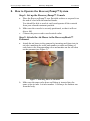
Step 4: Put on the RecoveryBoots™ Garment
For Leg Garment
a. Zip the leg garment closed at least part of the way up before
inserting your leg
b. Insert your foot into the garment (see Figure 4). Pull the top
of the garment towards your torso, extending the garment to
its maximum length.
c. Close the zipper all the way up.
d. Repeat for other leg, if desired. The RecoveryBoots™ leg
garment is designed to fit on either the right or left leg.
Figure 4 - Putting on the RecoveryPump™ Garment
L98101RA-A
9
RecoveryPump™ Model 701RA
Recovery Pump LLC
User Manual
For Arm/Shoulder Garment
a. Zip the arm garment closed at least part of the way up before
inserting your arm.
b. Insert your arm into the arm garment, pulling it over your
shoulder. Make sure the zipper is facing up, and that the cutout area is under your armpit.
c. Close the zipper all the way up. Support your arm on an
armrest or a pillow during the massage treatment. Supporting
the arm in a horizontal position allows the garment to cover
the shoulder area.
d. If the garment tends to slide down, use the optional belt. To
use the belt, attach one end of the belt to the snap closure at
the back of the garment, then pull on the sleeve, zip it closed,
pull the belt around your body under the opposite arm and
fasten it to the other snap closure at the front. When correctly
fastened, the belt should cross from the shoulder of the arm,
across the chest and under the opposite arm. Tighten the belt
just enough to keep the sleeve from slipping down.
For all Garments
The garment should not fit too tightly; you should be able to insert
three fingers into the garment when it is zipped closed before
inflation. If the garment is too tight, you will need a larger size.
Contact your RecoveryPump™ dealer.
Make sure the garment is zipped completely closed before turning
on the RecoveryPump™, and leave it closed for the duration of
the treatment. At the end of treatment, the garment will deflate
within a short time, allowing it to be removed easily. You should
be able to slip the garment off and pull it on again for each use
without completely unzipping the garment.
Note:
Do not use any garment other than the RecoveryBoots™ Garment
with the RecoveryPump™ console.
10
L98101RA-A
RecoveryPump™ Model 701RA
Recovery Pump LLC
User Manual
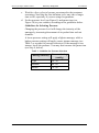
Step 5: Connect the Air Hoses to the RecoveryPump™
Console
a. Securely insert the hose bundle connector, with the logo facing
up, into one of the air sockets on the console (see Figure 5).
Figure 5 - Connecting the Air Hoses to the RecoveryPump™ Console
b. If you are using only one garment, insert the Prong Plug into the
unused air outlet This will prevent air from escaping through the
unused air outlet (see Figure 6).
Insert Prong Plug into
unused air outlet
Figure 6 - Inserting the Prong Plug to Block The Unused Air Outlet for Single Garment Use
L98101RA-A
11
RecoveryPump™ Model 701RA
Recovery Pump LLC
User Manual
c. Make sure the air hoses are not bent, kinked or pinched.
Note:
When only one garment is used, the second outlet must be plugged
with the Prong Plug. Otherwise the console will stop working and
the alarm buzzer will beep.
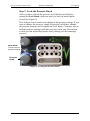
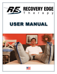
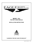
Step 6: Select Pressure Level
a. The first time you use the RecoveryPump™, set the Pressure Knob
and the Pause Knob to their minimum settings (see Figure 7).
Pause Knob
Lock Knob
Air Outlets
Prong Plug
Storage
Socket
Pressure
Knob
Figure 7 - General View of the RecoveryPump™ Front Panel
b. Turn On the RecoveryPump™ by pressing the ON/OFF switch at the
bottom right side of the console to the ON position (see Figure 8).
ON/OFF Switch
Figure 8 - The ON/OFF Switch
12
L98101RA-A
RecoveryPump™ Model 701RA
Recovery Pump LLC
User Manual
c. Wait for a few cycles to become accustomed to the treatment
sensations. Note that the first inflation cycle may take a longer
time to fill, especially if you are using two garments.
d. Set the pressure level (see Figure 9) and pause time (see
Figure 10) to your comfort, according to the guidelines below.
Guidelines for Selecting Pressure
Changing the pressure level will change the intensity of the
massage by increasing the amount of air pushed into each air
chamber.
A lower pressure setting will apply a lighter massage; while a
higher pressure setting will apply a more intense massage (see
Table 1 as a guide for pressure selection). If the massage is too
intense, lower the pressure. You may also increase the pause time
(see Step 8, below).
Table 1 - Guideline for Pressure Selection
Massage Intensity
L98101RA-A
Pressure Setting
(mmHg)
Light
20 - 30
Medium
40 - 60
Intense
70 - 80
13
RecoveryPump™ Model 701RA
Recovery Pump LLC
User Manual
Step 7: Lock the Pressure Knob
After you have selected the pressure, lock the Pressure Knob by
turning the Lock Knob clockwise until you feel the knob tighten
closed (see Figure 9).
This will prevent an inadvertent change in the pressure settings. If you
want to change the pressure, simply loosen the Lock Knob, change
the pressure settings, and re-tighten the Lock Knob. (You may wait to
lock the pressure settings until after you have tried your first session,
so that you can adjust the pressure easily during your first massage
session.)
Lock Knob
Turn this to lock
pressure setting
Pressure
Knob
Figure 9 - Locking the Pressure Knob
14
L98101RA-A
RecoveryPump™ Model 701RA
Recovery Pump LLC
User Manual
Step 8: Set the Pause Time
“Pause” is the time that the garments deflate and remain relaxed
between each massage cycle. Select this time by turning the Pause
Knob (see Figure 10).
Changing the pause time allows you to modify the massage by
increasing the pause interval in between massage waves.
Standard setting for pause time is 10 to 15 seconds.
Pause Knob:
Turn to select
Pause Time
Figure 10 - Setting the Pause Time
Considerations for Choosing Pause Time
Changing the pause time adjusts the length of the time the
garments are deflated in between each massage wave. If you
would like a more rapid massage pace, select a shorter pause
interval. If you want to slow down the massage pace, select a
longer pause interval (see Table 2).
Table 2 - Guideline for Pause Time Selection
Pause Duration
Pause Time
(seconds)
L98101RA-A
Short Pause Interval
10 - 20
Medium Pause Interval
30 - 50
Long Pause Interval
60 - 70
15
RecoveryPump™ Model 701RA
Recovery Pump LLC
User Manual
If you experience tingling or numbness during the massage
treatment anywhere in the treated area, increase the pause time to
30 to 45 seconds or more. If this sensation persists after increasing
the pause time, reduce the pressure. If this sensation continues,
stop using the system immediately and consult your physician.
When using two large garments, a longer pause time may be
necessary to ensure that all the air deflates from the garments in
between massage cycles. The RecoveryPump™ will not inflate
the garments if the air from the previous cycle has not adequately
emptied. If the pause time you selected is too short for adequate
deflation, the console will automatically double the pause time. If
this is bothersome, increase the pause time slightly and try again.
Step 9: Continue the Massage Session
Continue the massage session for the length of time you desire, for up
to 45 minutes per massage session.
Using RecoveryPump™ as a relaxing, invigorating massage before
you exercise will increase circulation and can help to get you into the
workout more quickly. Suggested treatment time is 15 to 30 minutes
before your workout. Or, use RecoveryPump™ for a relaxing
massage at the end of the day, or after exercise, to relax and soothe
tired, aching muscles. Generally, we recommend 30-45 minutes after
working out or in the evening after going about your daily activities.
!
16
Warning:
The massage sensation should be pleasant and comfortable.
If you experience pain or discomfort during or after the
massage treatment, discontinue use and consult your
physician.
L98101RA-A
RecoveryPump™ Model 701RA
Recovery Pump LLC
User Manual
Step 10: Ending the Massage Session
To end treatment, shut OFF the RecoveryPump™ using the ON/OFF
switch. Remove the garments. Unplug the console from the wall
socket.
We recommend that you do not disconnect the hoses from the
garment. If you need to disconnect the hoses from the garment, do
this by gently working the end fitting free from the air inlet using a
twisting/pulling motion.
Note:
If the RecoveryPump™ stops working and the warning signal
beeps, it means that the time needed to fill up the garment is too
long. Usually this is due to air leakage because the air hoses are not
properly connected, or because one of the air outlets on the console is
unplugged.
If this happens, turn Off the console at the ON/OFF switch, and then:
1. Check that all the hose ends are correctly inserted into the air
inlets.
2. Check that the hose connectors are properly connected to the air
outlets on the console.
3. If using only one garment, make sure that the unused outlet is
plugged with the Prong Plug.
If all the connections are OK and the problem persists, contact
Recovery Pump LLC.
In the case of a power failure or malfunction:
1. Turn Off the console at the ON/OFF switch.
2. Take off the garment(s)
3. Remove the electrical cord from the wall outlet.
4. If the system has malfunctioned, contact Recovery Pump LLC.
For more details, see Section 10 - Troubleshooting.
L98101RA-A
17
RecoveryPump™ Model 701RA
Recovery Pump LLC
User Manual
9. Maintenance and Storage
!
Warnings:
! Only an authorized technician may open the console.
! Before cleaning the console, disconnect the power cord from the
electrical wall outlet.
Cleaning the RecoveryPump™ Console
! Gently wipe the outside of the console using a nonabrasive cloth.
! Do not spill any liquids on the console.
Cleaning the RecoveryBoots™ Garments
Never submerge the garments in liquid. They are cleanable by surface
wiping only. Gently wipe the inner and outer surfaces of the garment
using a soft cloth moistened with warm water (not exceeding 100°F /
40°C) and a mild detergent. Do not allow water to enter the air inlets
of the garment at any time. If needed, a soft brush can be used to
remove stubborn dirt. Then towel dry and surface wipe again with a
soft cloth moistened in water to remove all detergent residue, again
taking care not to allow liquid to enter the air inlets. Towel dry and
then allow the garment to air dry completely before use.
If desired, the inner and outer surfaces of the garment may be wiped
down with a cloth or wipe moistened with a small quantity of
50% alcohol. Work in a well-ventilated area, and wear gloves. Allow
the garment to air dry completely before use.
!
18
Warnings:
! Clean only according to instructions.
! Do not hand or machine wash, dry clean, hand or power wring,
iron, tumble or force heat dry.
! Surface wipe only!
! Do not use bleach!
L98101RA-A
RecoveryPump™ Model 701RA
Recovery Pump LLC
User Manual
Storage
a. Store in a dry, shaded place at temperatures between -4°F to
158°F.
b. Roll up the power cord neatly before storing the console. Do not
bend or kink the cord.
c. Since the garment is inflated by air, it must remain airtight.
Therefore, avoid contact with pins, needles and any other sharp
objects or instruments. If one of the inflatable chambers is
damaged, the garment must be replaced.
d. The hoses should be kept untwisted and unfolded. Roll them up
neatly.
Transport
Transport in original packaging or in luggage with padding.
It is easier to check the console in baggage than to carry-on the
console for air travel.
L98101RA-A
19
RecoveryPump™ Model 701RA
Recovery Pump LLC
User Manual
10. Troubleshooting
Note:
Before continuing, check all accessories visually for any defects.
Table 3 - Troubleshooting Guide
Symptom
The console is not
working.
The console starts
working and stops
immediately.
Possible Cause
No electricity.
Check the electrical wall outlet.
Power cord.
Check the power cord visually for any
defects.
Fuses.
Check the fuses and replace if necessary.
If they burn out again, contact Recovery
Pump LLC.
The air cannot move
through the hose
bundle.
Check hose bundles for kinks, twists and
folds.
One garment inflates but The second garment
the second one does not. does not receive air.
The console stops
working and buzzer
beeps.
Hose bundle is not
connected properly to
garment or console, or
Prong Plug is not
inserted into unused
air outlet.
Defective garment
The console works at a
very low pressure,
An internal problem
regardless of the pressure
set by the user.
An irregular noise.
Check its hose bundle for kinks, twists
and folds.
Check and fasten all air connections. If
treating only one limb, make sure the
unused air outlet is plugged with the
prong plug provided with the console. If
all air connections are OK and problem
persists, contact Recovery Pump LLC.
Replace garment and check again.
Contact Recovery Pump LLC.
Console transferring Make sure the console is standing evenly
vibrations to a surface on all four of its bumpers, or is hung
properly on its hooks while supported by
the two rear bumpers.
An internal problem.
20
Corrective Action
Contact Recovery Pump LLC.
L98101RA-A
RecoveryPump™ Model 701RA
Recovery Pump LLC
User Manual
11. Warranty and Contact Information
Manufacturer Address
Mego Afek AC Ltd., Kibbutz Afek, 30042 Israel
Warranty
! Mego Afek AC Ltd. warrants the RecoveryPump™ Model 701RA
and RecoveryPump™ garments to be free of defects in materials
and workmanship.
! This warranty applies as follows:
! RecoveryPump™ console: for a period of twelve (12) months
from date of purchase.
! RecoveryPump™ garments: for a period of six (6) months
from date of purchase.
! This warranty does not include or cover malfunctions caused by
unreasonable use, noncompliance with user and maintenance
instructions, or damage caused by unauthorized or unqualified
repairs.
Imported to the USA by:
Lympha Press USA, Ltd. Manalapan, NJ 07726, USA
Distributor in the USA
Recovery Pump LLC
9 La Crue St. Suite 2
Concordville, PA 19331
Toll Free:
L98101RA-A
855-732-7867
21
RecoveryPump™ Model 701RA
Recovery Pump LLC
User Manual
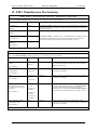
12. EMC Manufacturer Declarations
Model 701RA - electromagnetic emissions - manufacturer declaration
The Model 701RA is intended for use in the electromagnetic environment specified below. The customer or the
user of the M odel 7 01 RA should assure that it is used in such an environment.
Emissions Test
Compliance
Electromagnetic environment - guidance
RF emissions
Group 1
The M odel 701RA uses RF energy only for its internal function. Therefore, its
RF emissions are very low and are not likely to cause any interference in nearby
electronic equipment.
CISPR 11
RF emissions
Class B
CISPR 11
Harmonic emissions
Not applicable
IEC 61000-3-2
Voltage fluctuations/flicker
emissions
Not applicable
The M odel 701RA is suitable for use in all establishments, including domestic
establishments and those directly connected to the public low voltage power
supply network that supplies buildings used for domestic purposes.
IEC 61000-3-3
Model 701RA - electromagnetic immunity - manufacturer declaration
The Model 701RA is intended for use in the electromagnetic environment specified below. The customer or the
user of the Model 701RA should assure that it is used in such an environment.
Immunity Test
IEC 60601 test
level
Compliance level
Electromagnetic environment - guidance
Electrostatic discharge
(ESD)
±6 kV contact
Complies
Floors should be wood, concrete or ceramic tile. If floors
are covered with synthetic material, the relative humidity
should be at least 30%.
±2 kV for power
supply lines
Complies
Mains power quality should be that of a typical commercial
or hospital environment.
±1 kV line to
line
Complies
Mains power quality should be that of a typical commercial
or hospital environment.
Complies
Mains power quality should be that of a typical commercial
or hospital environment. If the user of the Model 701RA
requires continued operation during power mains
interruptions, it is recommended that the Model 701RA be
powered from an uninterruptible power supply or a UPS.
Complies
Power frequency magnetic fields should be at levels
characteristic of a typical location in a typical commercial
or hospital environment.
±8 kV air
IEC 61000-4-2
Electrical fast
transient/burst
IEC 61000-4-4
Surge
IEC 61000-4-5
±2 kV line to
erth
Voltage dips, short
interruptions and voltage
variations on power supply
input lines
IEC 61000-4-11
>95% dip in U T
for 10ms
60% dip in U T
for 100ms
30% dip in U T
for 500ms
>95% dip in U T
for 5000ms
Power frequency (50/60
Hz) magnetic field
3 A/m
IEC 61000-4-8
NOTE: U T is the a.c. mains voltage prior to application of the test level.!
R
22
R
L98101RA-A
RecoveryPump™ Model 701RA
Recovery Pump LLC
User Manual
Model 701RA - electromagnetic immunity - manufacturer's declaration
The Model 701RA is intended for use in the electromagnetic environment specified below. The customer or the user of the
Model 701RA should assure that it is used in such an environment.
Immunity test
IEC 60601 test level Compliance level
Electromagnetic environment - guidance
Portable and mobile RF communications equipment should be used no closer
to any part of the Model 701RA, including cables, than the recommended
separation distance calculated from the equation applicable to the frequency
of the transmitter.
Recommended separation distance
Conducted RF
IEC 61000-4-6
3 Vrms
150 kHz to 80 MHz
3 Vrms
d = 1,2 P
Radiated RF
IEC 61000-4-3
3 V/m
80 MHz to 2,5 GHz
3 V/m
d = 1,2 P 80 MHz to 800 MHz
d = 2,3 P 800 MHz to 2,5 GHz
Where P is the maximum output power rating of the transmitter in watts (W)
according to the transmitter manufacturer and d is the recommended
separation distance in meters (m).
Field strengths from fixed RF transmitters, as determined by an
electromagnetic site survey,a should be less than the compliance level in each
frequency range" b
P
P
P
Interference may occur in the vicinity of equipment marked with the
following symbol:
NOTE 1: At 80 MHz and 800 MHz, the higher frequency range applies"
NOTE 2: These guidelines may not apply in all situations. Electromagnetic propagation is affected by absorption and reflection from structures, objects
and people"
a
b
Field strengths from fixed transmitters, such as base stations for radio (cellular/cordless) telephones and land mobile radios, amateur radio, AM
and FM radio broadcast and TV broadcast cannot be predicted theoretically with accuracy. To assess the electromagnetic environment due to
fixed RF transmitters, an electromagnetic site survey should be considered. If the measured field strength in the location in which the Model
701RA is used exceeds the applicable RF compliance level above, the Model 701RA should be observed to verify normal operation. If
abnormal performance is observed, additional measures may be necessary, such as re-orienting or relocating the Model 701RA"
Over the frequency range 150 kHz to 80 MHz, field strengths should be less than 3 V/m"
Recommended separation distances between portable and mobile RF communications equipment
and the Model 701RA
The Model 701RA is intended for use in an electromagnetic environment in which radiated RF disturbances are controlled. The customer or the user of
the M o d e l 7 0 1 R A can help prevent electromagnetic interference by maintaining a minimum distance between portable and mobile RF
communications equipment (transmitters) and the M o d e l 7 0 1 R A as recommended below, according to the maximum output power of the
communications equipment.
Rated maximum output power
of transmitter
W
0,01
0,1
1
10
100
Separation distance according to frequency of transmitter
m
150 kHz to 80 MHz
d = 1,2 P
0,12
0,38
1,2
3,8
12
80 MHz to 800 MHz
d = 1,2 P
0,12
0,38
1,2
3,8
12
800 MHz to 2,5 GHz
d = 2,3 P
0,23
0,73
2,3
7,3
23
For transmitters rated at a maximum output power not listed above, the recommended separation distance d in meters (m) can be estimated using the
equation applicable to the frequency of the transmitter, where P is the maximum output power rating of the transmitter in watts (W) according to the
transmitter manufacturer"
NOTE 1: At 80 MHz and 800 MHz, the separation distance for the higher frequency range applies"
NOTE 2: These guidelines may not apply in all situations. Electromagnetic propagation is affected by absorption and reflection from structures, objects
and people.
L98101RA-A
23