1
GTC – SOFTWARE DEVELOPMENT GROUP
SIDEKICK PC
USER’S MANUAL
VERSION 2.02
© 2011 Electrolux Italia S.p.A., All rights reserved
File: SidekickPC Manual (EN).pdf - Date: 11/05/2011
1
GTC – SOFTWARE DEVELOPMENT GROUP
TABLE OF CONTENTS
1. INTRODUCTION ............................................................................................................... 3
1.1. ACRONYMS AND ABBREVIATIONS .................................................................... 4
1.2. SYSTEM REQUIREMENTS...................................................................................... 5
1.3. AUTOMATIC SOFTWARE INSTALLATION......................................................... 6
1.3.1. Overriding the default installation folder ................................................................. 7
1.3.2. Disabling Driver Signature Enforcement in Windows Vista 64-Bit Editions .......... 8
1.3.3. Setup of the USB drivers for the Appliance Connection Kit ................................. 10
1.3.4. Uninstalling SidekickPC......................................................................................... 11
1.4. SOFTWARE INITIALIZATION .............................................................................. 12
1.4.1. License Activation .................................................................................................. 12
1.4.2. Internet Settings ...................................................................................................... 14
1.4.3. Update Dialog ......................................................................................................... 15
1.4.4. Software Auto Update ............................................................................................ 20
1.4.5. Database Update ..................................................................................................... 21
2. HARDWARE CONNECTIONS...................................................................................... 23
2.1. CONNECTING THE APPLIANCE TO THE PC .................................................... 23
2.2. DISCONNECTING THE APPLIANCE FROM THE PC ........................................ 26
2.3. CONNECTING THE SPARE BOARD TO THE PC ............................................... 27
2.4. DISCONNECTING THE SPARE BOARD FROM THE PC................................... 29
3. SOFTWARE OPERATION............................................................................................. 30
3.1. SPARE BOARD INFORMATION FORM .............................................................. 33
3.2. STARTUP FORM ..................................................................................................... 36
3.3. CONFIGURATION FORM ...................................................................................... 38
3.3.1. Configuration Form Menu Commands................................................................... 43
3.3.2. Printing Extended Information in the label ............................................................ 47
3.4. IDENTIFICATION FORM ....................................................................................... 52
3.5. HISTORY FORM...................................................................................................... 54
3.6. MONITOR FORM .................................................................................................... 55
3.6.1. Troubleshooting Wizard ......................................................................................... 57
3.7. GRAPH FORM ......................................................................................................... 60
3.8. DIGITAL I/O FORM ................................................................................................ 61
3.9. APPLIANCE INFORMATION ................................................................................ 62
4. APPENDIX ........................................................................................................................ 66
4.1. MANUAL SOFTWARE INSTALLATION ............................................................. 66
4.1.1. SidekickPC Setup ................................................................................................... 66
4.1.2. SQL Server Management Studio Express Setup .................................................... 78
4.2. TROUBLESHOOTING SETUP PROBLEMS ......................................................... 81
4.2.1. Manual installation of prerequisites ....................................................................... 81
4.2.2. SQL Server installation problems........................................................................... 81
© 2011 Electrolux Italia S.p.A., All rights reserved
File: SidekickPC Manual (EN).pdf - Date: 11/05/2011
2
GTC – SOFTWARE DEVELOPMENT GROUP
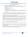
1. INTRODUCTION
Sidekick Enterprise Solution is a standard system designed by the Global Technology
Center (GTC) department of Electrolux for the after sales support organization. The main target of
this system is to provide field support engineers with a handy tool that, together with proper interface
modules, simplifies the execution of diagnostic procedures and that allows an easy way to configure
electronic boards.
Sidekick is an enterprise-wide system that integrates the most up-to-date information about Electrolux
products into a client software tool. The client software (SidekickPC) lets you quickly diagnose
appliances and create spare electronic boards. This is the User‟s Manual of this application.
Data integration between corporate databases and SidekickPC seamlessly occurs by means of web
services that exploit the latest technologies in order to minimize update time and improve user
experience and security.
There are many advantages in using a computer-aided service tool, for example:
1. the possibility to diagnose the appliances in less time and in a more precise way, thus reducing
the amount of spare components required to fix the problem and the time of intervention.
SidekickPC identifies if possible the appliance to test, gets and decodes the internal status of
the electronic controller, and it executes the diagnostic procedures and troubleshooting steps
you require;
2. the possibility to create spare electronic boards starting from “generic boards” with a
programming and configuration procedure. This function ensures that you create the spare part
in the same way as it was originally produced in the factory.
© 2011 Electrolux Italia S.p.A., All rights reserved
File: SidekickPC Manual (EN).pdf - Date: 11/05/2011
3
GTC – SOFTWARE DEVELOPMENT GROUP
1.1. ACRONYMS AND ABBREVIATIONS
AMI
ANC
ACK
BITS
BMP
CCF
CTI
DNS
ELC
ESD
GIF
HTML
IP
JPG
LBL
MCF
MDAC
MDI
MMC
PC
PNC
PNG
Prog
SKC
SP1
SSE
TCP
TDS
TIFF
URL
USB
WMI
WSE
Appliance Mini Interface
Article Number Code
Appliance Connection Kit
Background Intelligent Transfer Service
Bitmap File
Cycle Configuration File
Cross Technology and Innovation
Domain Name System
Engineering Level Code
Electrostatic Discharge
Graphic Interchange Format
Hyper Text Markup Language
Internet Protocol
Graphics file type developed by the Joint Photographic Experts Group
Label Definition File extension
Machine Configuration File
Microsoft Data Access Components
Multiple Document Interface
Microsoft Management Console
Personal Computer
Product Number Code
Portable Network Graphics
Progressive Insertion Number
Service Kit Code
Service Pack 1
Service Support Europe
Transmission Control Protocol
Technical Documentation System
Tagged Image File Format
Uniform Resource Locator
Universal Serial Bus
Windows Management Instrumentation
Web Services Enhancements
© 2011 Electrolux Italia S.p.A., All rights reserved
File: SidekickPC Manual (EN).pdf - Date: 11/05/2011
4
GTC – SOFTWARE DEVELOPMENT GROUP
1.2. SYSTEM REQUIREMENTS
Software prerequisites for SidekickPC are the following:
1. Microsoft Windows XP SP2, Vista (except the Starter Edition) and Windows 7. Both 32bit and 64-bit versions of Windows XP, Windows Vista and Windows 7 are supported.
2. Microsoft Windows Installer 3.1
3. MDAC 2.8
4. Microsoft .NET Framework 2.0
5. Microsoft WSE 3.0
6. Microsoft Internet Explorer 6.0 SP1 or later
7. Microsoft SQL Server 2005 Express Edition SP2 or SQL Server 2008 Express Edition. If
in your PC you have already installed another edition of SQL Server 2005/2008, this item is
not required.
Microsoft Internet Explorer 6.0 SP1 is software prerequisite for all installations of SQL Server 2005,
as it is required for Microsoft Management Console (MMC) and HTML Help. A minimal installation
of Internet Explorer is sufficient, and Internet Explorer is not required to be the default browser.
The automatic installation procedure of SidekickPC, installs all software pre-requisites and the
SidekickPC software using default settings in an unattended way.
The installation procedure automatically installs Microsoft SQL Server Express Edition 2005 SP2 only
if it does not detect the presence of an SQL Server 2005 or SQL Server 2008 instance in the local
computer.
The detection of the presence of SQL Server instances occurs by means of the Windows Management
Instrumentation (WMI) technology. In case the software installation procedure detects the presence of
more than one instance of SQL Server, the selected database instance will be the first Express Edition
that WMI enumerates or, if no Express Edition is present, the first enumerated instance.
If you want to override the default installation parameters of SidekickPC, you must install it manually.
Please refer to the appendix for further information on this matter.
If none of the software prerequisites is installed, the target PCs needs at least 15 GB of free hard disk
space.
The minimum RAM quantity required is 512 MB (1 GB highly recommended) while the minimum
processor speed required is 1 GHz. A CD or DVD drive, as appropriate, is required for installation
from CD or DVD media.
SidekickPC requires at least a monitor resolution of 1024x768 pixels for best usability. However it is
also possible to install it in PCs with a screen resolution of 1024x600 pixels. In this case, a vertical
scroll bar allows you accessing the entire contents of the user interface forms.
© 2011 Electrolux Italia S.p.A., All rights reserved
File: SidekickPC Manual (EN).pdf - Date: 11/05/2011
5
GTC – SOFTWARE DEVELOPMENT GROUP
1.3. AUTOMATIC SOFTWARE INSTALLATION
The automatic installation procedure consists in the AutoInstall.cmd command file. This is a
sequence of batch commands that install all software pre-requisites and the SidekickPC software using
default settings.
You must log on as full Administrator in order to make the installation of the software.
By default, the automatic software installation procedure installs SidekickPC in the
C:\Electrolux\SidekickPC folder.
You can however override this default and setup the software in a different directory. Please refer to the
next paragraph if you need to change the default installation directory.
The following recommendations apply:
1. Windows XP: simply double-click the AutoInstall.cmd file.
2. Windows VISTA and Windows 7: right-click the AutoInstall.cmd file and then select the "Run as
Administrator" option. Depending on your actual configuration, the operating system may ask you for
a further authorization. Please remember that, under Microsoft Vista, you must explicitly execute
AutoInstall.cmd as administrator even if you are already logged in with an administrative account.
If you are using a 64-bit edition of Windows Vista or Windows 7, please refer to paragraph 1.3.2 that
describes how you can disable Driver Signature Enforcement so that you can successfully install and
use the USB drivers for the appliance interface module.
Please remember that this setup procedure does not install the programs that are already installed in your
PC. In addition, the automatic setup procedure implements some workarounds to a few known setup
problems of the SQL Server 2005 software. One of these workarounds consists in temporarily disabling
network connectivity during the setup of this software. For this reason, please do not worry if you see a
warning that refers to a "limited network connectivity" issue during the setup.
Another workaround consists in uninstalling and re-installing the SQL Server 2005 Client Tools.
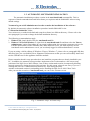
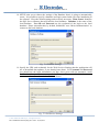
After you start the execution of AutoInstall.cmd, you can see the welcome screen:
Fig. 1. Automatic setup: welcome setup
© 2011 Electrolux Italia S.p.A., All rights reserved
File: SidekickPC Manual (EN).pdf - Date: 11/05/2011
6
GTC – SOFTWARE DEVELOPMENT GROUP
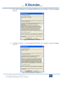
If you press CTRL+C you can abort the procedure.
If you press instead any other key combination, the automatic setup starts. Depending on your computer
configuration, the setup procedure may last several minutes.
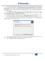
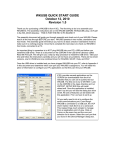
At the end of the automatic setup process, you can see the list of installed software packages:
Fig. 2. Automatic setup: end of procedure
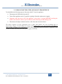
There is the possibility that during the setup sometimes goes wrong. In order to help you solve setup
problems Electrolux has documented all known setup issues and workarounds.
You can find the solution for these problems here:
http://sidekick.electrolux.com/SidekickPortal/UsersReservedArea/DownloadDetails.aspx?ContentID=
ApplicationNote3
In case you have problems with the automatic setup procedure, you should try installing SidekickPC in
a manual way. Please refer to the Appendix for information concerning the manual setup.
1.3.1. Overriding the default installation folder
If you want to install SidekickPC in an automatic way but not in the default folder
(C:\Electrolux\SidekickPC), you can open the AutoInstall.cmd file with any text editor (such as, for
example, Notepad) and change the following line:
SET SK_DIR=C:\Electrolux\SidekickPC
You should assign to the SK_DIR environment variable the full path of the target directory. For example,
if you want to install the software in the D:\ driver instead of the C:\ one you can change the line in the
following way:
SET SK_DIR=D:\Electrolux\SidekickPC
Then you should save the file and quit the editor. Finally run the modified AutoInstall.cmd command as
the previous paragraph describes.
Please ensure that SK_DIR is assigned a valid folder name.
© 2011 Electrolux Italia S.p.A., All rights reserved
File: SidekickPC Manual (EN).pdf - Date: 11/05/2011
7
GTC – SOFTWARE DEVELOPMENT GROUP
In addition, please remember that you cannot install SidekickPC within the following special directories:
1. Program Files: this is the folder that usually contains applications. In English versions of the
operating system this is the C:\Program Files folder;
2. Common Application Data: this is the common application data folder. In English versions
of the operating system this is the C:\Documents and Settings\All Users\Application Data
folder;
3. System: this is the folder that contains system files. In English versions of the operating
system this is the C:\Windows\System32 folder.
The setup process by design does not allow you installing SidekickPC in the Program Files folder, in
order to avoid functional problems under MS-Vista when you execute the program from a limited user
account. In this case, the “Virtual Store” feature in MS-Vista would prevent the proper operation of
the program.
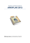
1.3.2. Disabling Driver Signature Enforcement in Windows Vista and Seven 64-Bit Editions
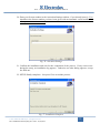
If you run the automatic setup procedure in a 64-bit edition of Windows Vista or Seven, you
get the following information message at the end of the installation:
Fig. 3. Automatic setup: end of procedure in Vista or Seven 64-bit
In 64-bit Windows Vista or Seven (x64 edition), Microsoft enforces requirement for loading of
kernel-mode software such as device drivers, filter drivers and services to have Kernel Mode Code
Signing (KMCS), especially driver binaries that load at boot time ("boot start drivers") which must
contain an embedded signature.
USB drivers for the Electrolux appliance interface modules do not contain a digital signature,
although they passed the tests for getting it. As a consequence, by default, you are not able to install
these drivers in all 64-bit versions of Windows Vista or Seven.
You must turn off Driver Signature Enforcement at boot time if you want to use unsigned
drivers.
© 2011 Electrolux Italia S.p.A., All rights reserved
File: SidekickPC Manual (EN).pdf - Date: 11/05/2011
8
GTC – SOFTWARE DEVELOPMENT GROUP
One way to disable Driver Signature Enforcement is by pressing F8 during initial boot of the
Windows Vista system, and then selecting Disable Driver Signature Enforcement in the “Advanced
Boot Options” menu. However this selection is only good for the session. In other words, you must
repetitively do the same thing (pressing F8 to disable signed driver enforcement) again and again on
every system reboot.
The “ReadyDriver Plus” utility allows you to automatically disable this feature at boot time.
You can install it with the "SetupReadyDriverPlus.exe" program that you can find in the “\USB
Drivers\ReadyDriver Plus” folder in the installation set.
You need to install this utility only once. In other words, if you install SidekickPC and then
you remove it and re-install it, you do not need to install ReadyDriver Plus the second time.
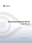
You should absolutely choose all default options in the setup program. The only option that
you may need to override is the number of keystrokes required to get to the Vista entry from the
default selection in the boot loader menu:
Fig. 4. ReadyDriver Plus setup: number of keystrokes
You should override the above default only if you have a multiboot configuration. In this case,
please refer to ReadyDriver Plus information that you can find in the internet.
After installing this utility, you must reboot the PC.
© 2011 Electrolux Italia S.p.A., All rights reserved
File: SidekickPC Manual (EN).pdf - Date: 11/05/2011
9
GTC – SOFTWARE DEVELOPMENT GROUP
1.3.3. Setup of the USB drivers for the Appliance Connection Kit
After completing the installation of SidekickPC, there is another important installation that you
must perform prior leaving the administrative mode in the PC: you must install the USB drivers for the
Appliance Connection Kit.
In order to perform this step you must have an Appliance Connection Kit (ACK) that Service Support
Europe (SSE) should have given you. You should connect the USB interface of the interface module
to the PC by means of the supplied cable. The operating system recognizes that this is the first time
that you connect the device to the PC and prompts you for the installation of the drivers.
The drivers are copied to the hard disk during the setup of SidekickPC in the USB Drivers directory
starting from the installation folder. The default driver directory is:
C:\Electrolux\SidekickPC\USB Drivers
You can find detailed instructions on how to setup the USB drivers in the “Appliance Interface
Modules USB Setup v 3.0” manual that is installed during the setup of SidekickPC.
Please remember that the sequence of operations that are required to install USB drivers varies a lot
depending on the actual operating system and configuration of your PC.
© 2011 Electrolux Italia S.p.A., All rights reserved
File: SidekickPC Manual (EN).pdf - Date: 11/05/2011
10
GTC – SOFTWARE DEVELOPMENT GROUP
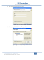
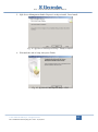
1.3.4. Uninstalling SidekickPC
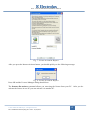
At a certain point you may want to remove the application from your PC. You can remove it as
any other Windows application by means of the Add/Remove Programs applet in the Control Panel.
Fig. 5. Removing the SidekickPC application
You must log on as full Administrator in order to remove the software.
When you remove SidekickPC, the uninstall procedure asks you if you want to delete also the local
SQL Server database. Please remember that, under Vista, the dialog box that asks you to remove or
not the database may be hidden by other windows: the uninstall procedure looks as if it is “frozen”. In
this case, you should just check for the presence of the dialog and choose “Yes” or “No” to continue.
© 2011 Electrolux Italia S.p.A., All rights reserved
File: SidekickPC Manual (EN).pdf - Date: 11/05/2011
11
GTC – SOFTWARE DEVELOPMENT GROUP
1.4. SOFTWARE INITIALIZATION
1.4.1. License Activation
After that you have successfully installed the program and the USB drivers you can log off as
Administrator and log on as a normal user. At any rate, the first thing that you are required to do the
first time you run SidekickPC is to activate the software license. Please remember that, in order to
activate the software license, your PC must be connected to the internet.
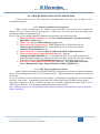
The first time you run the software, you can see this message:
Fig. 6. License Activation Request
After you press the OK button, you should execute a few initial configuration steps for your software:
Language (optional)
Internet Settings (mandatory when your PC is not directly connected to the internet)
License Activation (mandatory)
You may want to choose a display language other than English. In this case you must use the dialog
box that you can see if you select the Language command in the Options menu.
If your PC is not directly connected to the internet, you must select proper Internet Settings. You can
see the corresponding dialog if you select the Internet Settings command in the Commands menu.
For detailed information on this matter, please refer to the corresponding section later in this chapter.
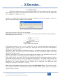
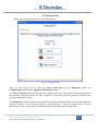
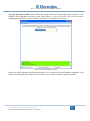
Finally, you must activate your software license by means of the License Manager dialog. You can
see this dialog if you select the License Manager command in the Commands menu. In most cases
you only need to specify the License Number (if you have not already specified it during manual
setup) and press the Internet Activate command:
© 2011 Electrolux Italia S.p.A., All rights reserved
File: SidekickPC Manual (EN).pdf - Date: 11/05/2011
12
GTC – SOFTWARE DEVELOPMENT GROUP
Fig. 7. License Activation Request
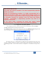
After you press the Internet Activate button, you should quickly see the following message:
Fig. 8. License Activation Request
Press OK and the License Manager dialog should close.
The Internet De-activate command allows you removing the license from your PC. After you deactivate the license in one PC you can activate it in another PC.
© 2011 Electrolux Italia S.p.A., All rights reserved
File: SidekickPC Manual (EN).pdf - Date: 11/05/2011
13
GTC – SOFTWARE DEVELOPMENT GROUP
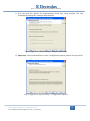
1.4.2. Internet Settings
If an internet connection error occurs, please verify that you are really connected to the network
and check your proxy settings in the dialog that you can activate in Commands >> Internet Settings:
Fig. 9. Internet Settings Dialog
Sometimes invalid proxy settings are the reason of internet license activation and local database update
failures. By default the setup program activates the option that uses “system default proxy settings”.
In some cases this option does not work and you must explicitly specify your proxy configuration.
The Connection Settings section lets you specify the way you are connected to the internet. The
following options are available:
1. Direct connection (don’t use proxy): use this option if your PC is directly connected to the
internet;
2. Use system default proxy settings: use the settings that you have specified in the Internet
Explorer web browser, if you have installed it in your PC. If the proxy you are using requires
explicit authentication (username and password), you cannot use this option but you must
explicitly specify credentials with the “Use the following proxy settings” option;
3. Use the following proxy settings: use this option to explicitly specify your proxy settings. If
you use this option you must fill-in the Proxy Settings section. The HTTP Proxy field allows
you to specify the DNS name or the IP address of your proxy. The default TCP port for the
proxy is 80. You can specify another port by separating the DNS name (or IP address) to the
port number by means of a colon. If your proxy requires authentication, you must specify also
the User Name, Password, and Domain fields.
© 2011 Electrolux Italia S.p.A., All rights reserved
File: SidekickPC Manual (EN).pdf - Date: 11/05/2011
14
GTC – SOFTWARE DEVELOPMENT GROUP
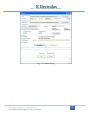
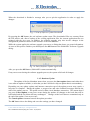
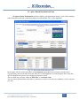
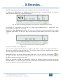
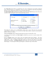
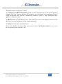
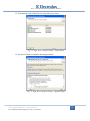
1.4.3. Update Dialog
The Update Dialog allows you to perform the update of the local database and the auto-update
of the software by means of a connection to the remote web server. You can activate this dialog with
the Commands >> Update menu item.
Opening the dialog, if the software loads from the configuration file wrong settings, a dialog box
advice you that all default parameters will be applied:
Fig. 10. Invalid Parameters Warning dialog
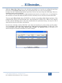
In this case all textbox in the form will be editable.
By default the content of all textbox is read-only; to edit the parameters, unlock the dialog clicking on
the bottom right side of the form.
Fig. 11. Lock/Unlock option
Local database updates occur in a very simple way and are executed through the interaction of
SidekickPC with a remote web service that copies information from the Electrolux central Sidekick
database to your local computer.
The software fully relies on the local database contents. You cannot operate the software if the local
database is empty. For this reason, you must perform the initial full database update, prior using
SidekickPC for the first time.
Software auto updates are instead executed through the interaction of the application with the web
portal which provides a dedicated section for the publication of update files.
Each update consists in a single ZIP file that contains all necessary information that you need to
perform the software update of your local installation of SidekickPC. The system first downloads this
file in your local PC, and then it extracts information and applies the software upgrade. For the
download of the software upgrade file, the software uses a technology from Microsoft called
Background Intelligent Transfer Service (BITS).
Both software and database updates start by clicking the Start update button. Every time you issue
this command, SidekickPC automatically checks for available software updates before executing the
database update procedure.
© 2011 Electrolux Italia S.p.A., All rights reserved
File: SidekickPC Manual (EN).pdf - Date: 11/05/2011
15
GTC – SOFTWARE DEVELOPMENT GROUP
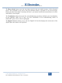
Fig. 12. Update Dialog
© 2011 Electrolux Italia S.p.A., All rights reserved
File: SidekickPC Manual (EN).pdf - Date: 11/05/2011
16
GTC – SOFTWARE DEVELOPMENT GROUP
The Remote Web Service section lets you specify the connection options for the web service:
1. Service URL: the intranet or internet address to reach the web service. Depending on the
different situations, you can use one of the following URLs:
a. http://sidekick.int.electrolux.com/SidekickService2/SidekickService.asmx
b. http://sidekick.electrolux.com/SidekickService2/SidekickService.asmx
Addresses containing the “int.electrolux” portion are only visible from inside the
Electrolux network or through the Access Manager application (intranet). Electrolux may
change or remove some of the above URLs in the future. For this reason, you should ask
Service Support Europe to know which address you should actually use in your case;
2. User Name and Password allow you to specify your personal credentials to access the web
service. You should use the User Name and Password that you receive by mail when your
license is activated. You can use the same credentials to enter also the reserved area in the
Sidekick web portal that, depending on the different situations, you can reach with one of
the following addresses:
a. http://sidekick.int.electrolux.com/SidekickPortal
b. http://sidekick.electrolux.com/SidekickPortal
Also for the URLs of the Sidekick web portal are valid the same remarks as the URLs for
the web service;
3. Connection Timeout: this option allows you to specify the maximum response time of the
web service in seconds. If your internet connection is very slow and you get a timeout error
during updates, you can increase this value and try again;
4. the Test connection command allows you to connect to the web service to verify if you
have specified the correct settings.
With the manual installation procedure, which this document describes in the appendix, you can
explicitly select the initial value for the options in this section. The automatic installation instead
defines default settings that you may need to override. For sure you must define at least your personal
credentials to access the web service: User Name and Password.
The Software Auto Update section lets you specify the internet address of the web portal section that
provides the auto update feature of the software:
1. Update URL: the intranet or internet address to reach the web portal. Depending on the
different situations, you can use one of the following URLs:
a. http://sidekick.int.electrolux.com/SidekickPortal/Media/SidekickPCUpgrade/manifest.xml
b. http://sidekick.electrolux.com/SidekickPortal/Media/SidekickPCUpgrade/manifest.xml
Addresses containing the “int.electrolux” portion are only visible from inside the
Electrolux network or through the Access Manager application (intranet). Electrolux may
© 2011 Electrolux Italia S.p.A., All rights reserved
File: SidekickPC Manual (EN).pdf - Date: 11/05/2011
17
GTC – SOFTWARE DEVELOPMENT GROUP
change or remove some of the above URLs in the future. For this reason, you should ask
Service Support Europe to know which address you should actually use in your case;
2. the Test connection command allows you to connect to the web portal to verify if you have
specified the correct internet address.
The Local Database section lets you specify the connection options for the local SQL Server
database:
1. Server: the name of the SQL Server instance that stores your local database. By default the
instance name is (local)\SQLEXPRESS. You select the server name at installation time
only if you perform the manual installation procedure as this document describes in the
appendix;
2. Database: the name of the local Sidekick database. By default the database name is
SidekickPC. You choose the database name at installation time only if you perform the
manual installation procedure as this document describes in the appendix;
3. the Use Windows NT Integrated Security option allows you to access the database
through the integrated security of the operating system;
4. the Use SQL Server user name and password option allows you to access the database
by means of explicit credentials. This is the default way to access to local database. The
User Name and Password fields allow you to specify your personal credentials to access
the database. You choose the user name and the password to access the local database at
installation time only if you perform the manual installation procedure as this document
describes in the appendix;
5. with the Connection Timeout and Command Timeout you can specify the connection
and command timeouts (in seconds) for the operations related to the local database.
Usually you do not need to alter these settings;
6. the Test Connection command allows you to connect to the database to verify if you have
specified the correct settings.
The Settings section lets you specify the type of the update and it shows the date and time of the last
update.
1. Full update: use this option if you want to perform a full update of the local database. In
this case all local data are removed (if any) prior executing a full copy of the remote
database contents to the local database. The full update involves all Electrolux appliance
models (PNCs) supported by SidekickPC. A full update is mandatory prior using the
software for the first time after the setup;
2. Incremental update: use this option if you want to download only the new records from
the remote database. This is the most common update after the initial setup. The
incremental update involves all Electrolux appliance models (PNCs) supported by
Sidekick;
© 2011 Electrolux Italia S.p.A., All rights reserved
File: SidekickPC Manual (EN).pdf - Date: 11/05/2011
18
GTC – SOFTWARE DEVELOPMENT GROUP
3. PNC update: use this option if you want to download only the new records related to a
certain set of PNCs from the remote database. The PNC List entry allows you to specify
the list of PNCs (one or more up to 20) that you are interested in. The PNC list is a
sequence of comma-separated PNCs. A PNC (Part Number Code) is a numeric code of 9
digits that identifies a certain appliance model from Electrolux. In the PNC List you
should not supply the ELC (Engineering Level Code): downloading data for a certain
PNC means getting the update for all related ELCs. Instead of commas you can also use
semicolons (;), hyphens (-), and forward slashes (/) as a separator. An example of a valid
PNC List the following one: 914791101,913101218,914521544;
4. Last update date (server date) displays the date and time of the last Full or Incremental
update. Keep in mind that this is the date of the server not the date of your local PC.
Please remember that the PNC update does not change this value;
5. the Enable log option creates a log file during the update process. This option is useful
for troubleshooting purposes.
The Start update command both starts the auto-update of the software and the update of the local
database.
If one of the URLs is a not allowed address an error dialog box is shown:
Fig. 13. Invalid URLs: error dialogs
© 2011 Electrolux Italia S.p.A., All rights reserved
File: SidekickPC Manual (EN).pdf - Date: 11/05/2011
19
GTC – SOFTWARE DEVELOPMENT GROUP
1.4.4. Software Auto Update
Every time you click on Start update button, the software checks if there is a software update
available.
If not, the process continues with the update of the local database. Instead, in case an update is
available, a dialog box that specifies a short description of the upgrade is shown:
Fig. 14. Optional Software Update Notification
If the update is mandatory, the software informs you that the update will be applied before proceeding
with the local database update. If the update is instead optional you can skip it and start immediately
the database update.
By clicking the Yes button the download of the upgrade files starts. During the download of the
software upgrade file, the Update dialog box shows you a progress bar and some messages that
indicate the state of the process.
© 2011 Electrolux Italia S.p.A., All rights reserved
File: SidekickPC Manual (EN).pdf - Date: 11/05/2011
20
GTC – SOFTWARE DEVELOPMENT GROUP
When the download is finished a message asks you to quit the application in order to apply the
changes.
Fig. 15. End of Software Update Download
By pressing the OK button, the real software update starts. The downloaded files are extracted from
the ZIP archive and, after a backup of the existing application files, the current application files are
replaced with the new ones. In addition, the software upgrade may also involve changes in the
configuration parameters and/or in the structure of the local database.
While the system applies the software upgrade you can see a dialog that shows you some information.
As soon as this process finishes you should press the OK button in the SidekickPC Software Upgrade
dialog:
Fig. 16. End of Software Update Application
After you press the OK button, SidekickPC restarts automatically.
If any errors occur during the software upgrade process, the system rolls-back all changes.
1.4.5. Database Update
The update of the local database starts when you press the Start update button and either there
is no software update available, or after that you have decided to skip an update that is not mandatory.
Depending on your update options and internet connection speed, the update process may require a
long time to complete. During the update, a progress bar and some feedback messages indicate the
state of the update process. The update occurs within a local database transaction. This means that if
you press Cancel update or any error occurs during the update, all changes to the local data will be
roll-backed and the local data will stay unchanged. Changes to the local data are committed only at
the end of the update, if no error occurs.
The Cancel update command cancels the update procedure.
The OK button closes the dialog and saves the settings you have changed.
© 2011 Electrolux Italia S.p.A., All rights reserved
File: SidekickPC Manual (EN).pdf - Date: 11/05/2011
21
GTC – SOFTWARE DEVELOPMENT GROUP
The Cancel button closes the dialog without saving the settings you have changed.
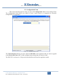
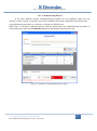
As previously specified, prior using SidekickPC for the fist time you must execute a Full update.
Please press the Test Connection buttons to check if the connections to the remote web service and to
the local database work. If necessary, select the Full Update option and then press the Start update
command. You should see feedback messages indicating the progress of the operation. The initial full
update may take several minutes or even hours to complete, please be patient. At the end you should
see the completion notification:
Fig. 17. Update Dialog: operation complete
Press OK and you are ready to start using the software.
© 2011 Electrolux Italia S.p.A., All rights reserved
File: SidekickPC Manual (EN).pdf - Date: 11/05/2011
22
GTC – SOFTWARE DEVELOPMENT GROUP
2. HARDWARE CONNECTIONS
This chapter provides information regarding the correct way to connect and disconnect the
Sidekick system to the appliance under test or to the electronic board to configure.
2.1. CONNECTING THE APPLIANCE TO THE PC
CAUTION!
In order to avoid the risk of electrical shock only skilled
personnel should use and install the Appliance Connection Kit.
The
connection of all items should occur only when the appliance is powered
off and, if possible, unplugged from the power supply. Also the adapter
module should be off.
If the Appliance Connection Kit uses the USB interface of your PC, please
remember that you should always employ a fully-shielded High-Speed
USB 2.0 cable. This type of USB cable provides a good level of reliability
for the communication between the PC and the appliance.
If you want to diagnose an appliance or update its electronic board configuration, you should connect
it to the PC. To connect the appliance to the PC you need to do the following steps:
Turn off the interface module (if it has a separate power supply).
If necessary, disconnect the interface module from the PC (disconnect the RS-232 cable or the
USB cable).
Turn off the appliance and, if possible, unplug it from the power supply.
Important: wait at least 5 seconds BEFORE touching the board or the interface cable to prevent
Electro Static Discharge (ESD) damage risk.
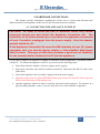
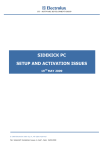
Open the appliance cabinet in order to reach the electronic board connector. For instance in a
typical washing-machine: remove 2 screws from the cover on the backside of appliance.
© 2011 Electrolux Italia S.p.A., All rights reserved
File: SidekickPC Manual (EN).pdf - Date: 11/05/2011
23
GTC – SOFTWARE DEVELOPMENT GROUP
Fig. 18. Appliance backside view
Typical washing-machine example: slide the top cover back and (if necessary) remove the
plastic shield from the electronic board using the plastic tips, which you find at each end. In
some types of appliance you only need to open the plastic tip that protects the interface
connector in the electronic board.
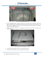
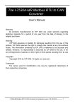
Connect the adapter module to the appliance using the interface cable as shown in the
following picture.
Fig. 19. Appliance with adapter connected
Connect back the appliance to the power supply and turn it on.
Turn on the adapter module (if it has a separate power supply).
© 2011 Electrolux Italia S.p.A., All rights reserved
File: SidekickPC Manual (EN).pdf - Date: 11/05/2011
24
GTC – SOFTWARE DEVELOPMENT GROUP
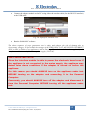
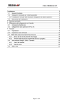
Connect the adapter module to the PC using either the modem cable (for the RS-232 interface)
or the USB cable.
USB
interf
ace
Fig. 20. Laptop PC backside view
Run the SidekickPC software.
The above sequence of steps guarantees user’s safety and reduces the risk of damage due to
electrostatic charges. It also avoids the storage of the FREQUENCY OF APPLIANCE INCORRECT
(EH1 or EB1 in Fabric Care appliances) alarm that is generated when the board is supplied by the
interface module instead of the mains power supply (230 VAC).
VERY IMPORTANT NOTE!
Since the interface module is able to power the electronic board even if
the appliance is not connected to the mains supply, the appliance may
detect false alarm conditions if the adapter is turned on before the
appliance.
For this reason you should ALWAYS turn on the appliance under test
BEFORE turning on the adapter and connecting it to the Personal
Computer.
Conversely, you should ALWAYS turn off the adapter and disconnect it
from the Personal Computer BEFORE turning off the appliance under
test.
© 2011 Electrolux Italia S.p.A., All rights reserved
File: SidekickPC Manual (EN).pdf - Date: 11/05/2011
25
GTC – SOFTWARE DEVELOPMENT GROUP
2.2. DISCONNECTING THE APPLIANCE FROM THE PC
You should do the following steps to disconnect the PC from the appliance:
Disconnect the USB cable from the PC.
Turn off the appliance and, if it possible, unplug it from the mains power supply.
Important: after the power off of the appliance, wait at least 5 seconds BEFORE touching the
board or the interface cable to prevent Electro Static Discharge (ESD) damage risk.
Disconnect the adapter module interface cable from the electronic board.
The above sequence of steps guarantees user’s safety and reduces the risk of damage due to
electrostatic charges. It also avoids the storage of the FREQUENCY OF APPLIANCE INCORRECT
(EH1 or EB1 in Fabric Care appliances) alarm that is generated when the board is supplied by the
interface module instead of the mains power supply (230 VAC).
© 2011 Electrolux Italia S.p.A., All rights reserved
File: SidekickPC Manual (EN).pdf - Date: 11/05/2011
26
GTC – SOFTWARE DEVELOPMENT GROUP
2.3. CONNECTING THE SPARE BOARD TO THE PC
CAUTION!
In order to avoid the risk of electrical shock only skilled personnel
should use and install the Appliance Connection Kit. You should NEVER
power on the spare board from the mains supply (230VAC) when it is not
installed in the appliance.
The adapter interface module provides the necessary power to the board
during the configuration procedure, without the need of connecting the
mains supply.
Before handling the electronic board, you should discharge your body
from possible electrostatic charges, by touching one conductive object
connected to earth.
In addition, you should never touch both neither the board nor the
adapter
module
interface
connector
during
configuration
program
download and, in general, when the board supply is present. These
precautions reduce the risk of damaging the electronic board because of
electrostatic discharges.
If you want to create a spare board for a specified appliance, you should connect the naked board to the
PC for the configuration. To connect the board to the PC you need to do the following steps:
Turn off the interface module (if it has a separate power supply).
© 2011 Electrolux Italia S.p.A., All rights reserved
File: SidekickPC Manual (EN).pdf - Date: 11/05/2011
27
GTC – SOFTWARE DEVELOPMENT GROUP
Connect the adapter module to the board using the interface cable as shown in the following
picture.
Fig. 21. Board with appliance cable connected
Connect the adapter module to the PC using either the modem cable (for the RS-232 interface)
or the USB cable and turn on the adapter module. This operation turns on the spare board as
well.
VERY IMPORTANT NOTES!
You may hear an intermittent beep when the spare board is powered on
by the adapter.
This beep is due to the fact that the board detects a
false alarm condition since it is not yet installed in the appliance.
When you turn on an appliance for the first time after you have
reconfigured it, or after you have replaced the electronic board, the
machine may automatically start the electric test (the electric test is
only used in the factory at the end of the assembly line).
appliance on and off to set it back in normal mode.
© 2011 Electrolux Italia S.p.A., All rights reserved
File: SidekickPC Manual (EN).pdf - Date: 11/05/2011
28
Turn the
GTC – SOFTWARE DEVELOPMENT GROUP
2.4. DISCONNECTING THE SPARE BOARD FROM THE PC
CAUTION!
In order to avoid the risk of electrical shock only skilled personnel
should use and install the Appliance Connection Kit. You should NEVER
power on the spare board from the mains supply (230VAC) when it is not
installed in the appliance.
The adapter interface module provides the necessary power to the board
during the configuration procedure, without the need of connecting the
mains supply.
Before handling the electronic board, you should discharge your body
from possible electrostatic charges, by touching one conductive object
connected to earth.
In addition, you should never touch both neither the board nor the
adapter
module
interface
connector
during
configuration
program
download and, in general, when the board supply is present. These
precautions reduce the risk of damaging the electronic board because of
electrostatic discharges.
You should do the following steps to disconnect the PC from the spare board:
Disconnect the USB cable from the PC.
Important: wait at least 5 seconds BEFORE touching the board or the interface cable to prevent
Electro Static Discharge (ESD) damage risk.
Disconnect the adapter module interface cable from the board.
© 2011 Electrolux Italia S.p.A., All rights reserved
File: SidekickPC Manual (EN).pdf - Date: 11/05/2011
29
GTC – SOFTWARE DEVELOPMENT GROUP
3. SOFTWARE OPERATION
This chapter deals with the SidekickPC utility functions. The program consists of a main
window that is a container of all other functional windows (forms). The main window follows the
Multiple Document Interface (MDI) approach. Using MDI allows you opening many forms at the
same time during the diagnostic procedure.
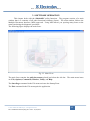
The following figure displays the main form:
Fig. 22. Main Form
The main form contains the pull-down menu placed just below the title bar. The main menu items
are: File, Options, Commands, Window, Utility, and Help.
The Start Page command in the File menu activates the Startup Form.
The Exit command in the File menu quits the application.
© 2011 Electrolux Italia S.p.A., All rights reserved
File: SidekickPC Manual (EN).pdf - Date: 11/05/2011
30
GTC – SOFTWARE DEVELOPMENT GROUP
The Communication command in the Options menu shows the Connection Settings dialog box
that allows specifying the maximum communication speed for connecting to the target appliance or to
the board:
Fig. 23. Connection Settings
You do not usually need to change any settings in this dialog box.
© 2011 Electrolux Italia S.p.A., All rights reserved
File: SidekickPC Manual (EN).pdf - Date: 11/05/2011
31
GTC – SOFTWARE DEVELOPMENT GROUP
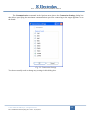
The Language command in the Options menu shows the Language dialog box that allows
choosing the display language:
Fig. 24. Language Selection
The Update command in the Commands menu shows the Update Dialog already described in Chapter
1.
The License Manager command in the Commands menu shows the License Manager Dialog already
described in Chapter 1.
The Internet Settings command in the Commands menu shows the Internet Settings Dialog already
described in Chapter 1.
The Windows menu contains various commands that simplify arrangement of forms in the workspace.
The Utility menu contains the Spare Board Information command that allows you to see all
information from TDS (Technical Documentation System) database about a spare board code, the
replacement history and the list of all PNC/ELC that are related to the selected board. The next
paragraph describes this function.
The Help menu contains only the command to display the About Dialog box.
© 2011 Electrolux Italia S.p.A., All rights reserved
File: SidekickPC Manual (EN).pdf - Date: 11/05/2011
32
GTC – SOFTWARE DEVELOPMENT GROUP
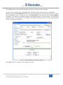
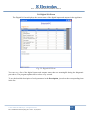
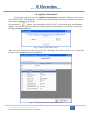
3.1. Spare Board Information Form
The Spare Board Information window displays all information about a spare board starting
either from the board code (with check digit) or from the PNC/ELC of the appliance.
Fig. 25. Spare Board Information Form
In the upper left side of this form there is the Selection group that lets you choose search criteria.
You can start your search either from the PNC/ELC of the appliance or from the Spare Part Code that
in TDS identifies the generic not configured electronic board.
The text field lets you enter either the PNC/ELC or the Board Code.
You can insert optional blank and slash (/) characters in order to increase the readability of the code that
you enter.
© 2011 Electrolux Italia S.p.A., All rights reserved
File: SidekickPC Manual (EN).pdf - Date: 11/05/2011
33
GTC – SOFTWARE DEVELOPMENT GROUP
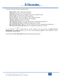
When you click the combo box, a drop-down list, containing the last 5 used codes appears.
If you press this button
, a list containing all the PNC/ELC Codes or Board Codes stored in the
database appears.
You can select one item from the generated list and you have the possibility to restrict the selection list by
filling the Starts with field.
Fig. 26. Board Code List and PNC/ELC List Forms
When you enter the code and press either the ENTER key or the OK button, SidekickPC searches for
matches with the specified code in the local database. If it finds the specified code, the software
automatically populates the form.
This form shows search results in 2 grids.
The upper grid provides the Board History that shows a list of spare board codes (with related Technical
Code) as well as additional information. In particular Replaced Spare Part Code shows the code of a
more recent board that replaces the board identified by the current record. If the value of this field is
(Empty) this board is the most recent one since it has not been replaced yet.
The software sorts the list so that the first record refers to the most recent board according to the
information from TDS.
The software highlights in red the board code used to populate the grid. At the upper right side of the form
the software also displays a picture of this board, if available.
© 2011 Electrolux Italia S.p.A., All rights reserved
File: SidekickPC Manual (EN).pdf - Date: 11/05/2011
34
GTC – SOFTWARE DEVELOPMENT GROUP
While the Spare Part Code refers to the code that you should use to buy the not configured board from
Electrolux, the Technical Code indicates the code that Electrolux uses to buy it from suppliers.
In many cases the Technical Code and the Spare Part Code are the same except the check digit. However,
sometimes, these codes are different.
The Technical Code is often printed in a label attached to the board or to its plastic case. As a consequence,
the code that you read in this label may differ from the code that you use to buy the part from Electrolux.
The lower grid, Where Used, shows all PNC/ELCs, with the corresponding Model, Brand, and date of first
production that employ the selected board code. This information is similar to the "Where Used" function
in TDS, with the advantage that it takes into consideration the replacement history, not only the bill of
material from factories at the date of production.
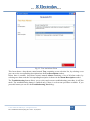
In some cases, selecting a code by PNC/ELC, more than one board may be present in that specific product.
As a consequence, more than one record may be found inside the local database. In this case a list
containing Spare Part Code, Plant, Board Name, Product, and Platform appears, allowing you to
choose the specific electronic board that you want to analyze.
Fig. 27. Board Selection Form
© 2011 Electrolux Italia S.p.A., All rights reserved
File: SidekickPC Manual (EN).pdf - Date: 11/05/2011
35
GTC – SOFTWARE DEVELOPMENT GROUP
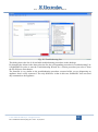
3.2. Startup Form
When you run the program you see the Startup form:
Fig. 28. Startup Form
There are four objects on the form: the Select COM port list, the Diagnostic button, the
Configuration button and the Appliance Information button.
The Select COM port list lets you choose the communication port. The software automatically detects
the available serial ports on the PC and, if possible, it selects the port that you have selected in the
previous SidekickPC session.
The Diagnostic button lets you start the appliance diagnostics function. When you press this button the
software connects to the appliance under test and identifies it. Then the program shows you the
Identification form with the main configuration parameters in the connected appliance.
© 2011 Electrolux Italia S.p.A., All rights reserved
File: SidekickPC Manual (EN).pdf - Date: 11/05/2011
36
GTC – SOFTWARE DEVELOPMENT GROUP
The Configuration button lets you enter to the board configuration function. When you press this
button, SidekickPC shows you the Board Configuration form.
The Appliance Information button lets you to get detailed information regarding test, alarms, and the
troubleshooting procedures of a specific appliance model that you identify by means of the PNC/ELC.
Please remember that this function only works for those appliances that SidekickPC is able to
diagnose.
© 2011 Electrolux Italia S.p.A., All rights reserved
File: SidekickPC Manual (EN).pdf - Date: 11/05/2011
37
GTC – SOFTWARE DEVELOPMENT GROUP
3.3. Configuration Form
This is the form that appears when you press the Configuration button in the Startup Form.
The Configuration form allows you either to create a spare board or to upgrade the electronic
configuration of an appliance.
Fig. 29. Configuration Form
The Code Selection field lets you enter either the PNC/ELC of the appliance that you want to upgrade
or the Service Kit Code (SKC) of the configured spare board that you want to create.
The PNC/ELC is always an 11-digit code that identifies the Electrolux appliance model.
© 2011 Electrolux Italia S.p.A., All rights reserved
File: SidekickPC Manual (EN).pdf - Date: 11/05/2011
38
GTC – SOFTWARE DEVELOPMENT GROUP
The SKC instead identifies the code of the configured spare board in the TDS system.
In Fabric Care, Dish Care, and Food Preservation product lines, configured boards are coded as
spare part for each PNC/ELC in the following way:
Fig. 30. SKC Convention for Fabric Care, Dish Care, and Food Preservation
As you can see, in the above case, the SKC a 15-digit code beginning with 973. A PNC/ELC code
corresponds to one SKC and vice versa.
Instead, the Food Preparation product line does not follow the previous convention for coding
configured spare boards. In this case, they use the factory Article Number Code (ANC) with a check
digit:
Fig. 31. SKC Convention for Food Preparation
In this case, the SKC is a 10-digit code.
You can insert optional blank characters, hyphens and slashes, between one digit and another, to
increase the readability of the inserted code. The software ignores all extra characters that you may
insert for improving the readability of the code.
SidekickPC keeps a list with the most recently used codes. You can click the select button (
) on
the right side of the Code Selection field and choose one of these items instead of manually entering
the digits each time you enter a new code.
When you press the ENTER key, SidekickPC searches for matches with the specified code in the
internal database. If it finds the specified code, SidekickPC automatically processes the information
for the configuration of the specified spare board.
© 2011 Electrolux Italia S.p.A., All rights reserved
File: SidekickPC Manual (EN).pdf - Date: 11/05/2011
39
GTC – SOFTWARE DEVELOPMENT GROUP
If the specified code does not exist in the database, the software just shows an error message.
If the specified code exists in the database, the corresponding Brand/Model and if available, two
images (photos of the naked board and the adapter) appear on the form.
You can then enter the number of identical boards to configure:
Fig. 32. Quantity Definition
© 2011 Electrolux Italia S.p.A., All rights reserved
File: SidekickPC Manual (EN).pdf - Date: 11/05/2011
40
GTC – SOFTWARE DEVELOPMENT GROUP
After the quantity definition, press the ENTER key again and you are ready to start the configuration.
This means that you can connect the appliance board to the PC and press OK to start the programming
procedure:
Fig. 33. Start Programming
When you press the OK button to start the configuration of the board, at first the program identifies the
naked board. If the naked board you are using is not suitable for the appliance model you have
selected, SidekickPC issues an error message and prevents you further actions with the board.
Otherwise it immediately starts the board configuration procedure.
The board configuration procedure occurs using the information contained in the local database.
During the execution of this command the target device goes into a special mode. After the
programming procedure, SidekickPC resets the board and it performs a check of the configuration.
© 2011 Electrolux Italia S.p.A., All rights reserved
File: SidekickPC Manual (EN).pdf - Date: 11/05/2011
41
GTC – SOFTWARE DEVELOPMENT GROUP
The Last operation results textbox shows the result of the last board programming operation. The
GREEN color highlights successful result, RED failure. In case of success, you can see statistics
regarding the operation. In case of failure you can see a description of the error:
Fig. 34. Last operation result
Please note that all board programming operations are recorded in the local database (Database Log)
and that are uploaded to the remote server whenever you execute a database update operation.
© 2011 Electrolux Italia S.p.A., All rights reserved
File: SidekickPC Manual (EN).pdf - Date: 11/05/2011
42
GTC – SOFTWARE DEVELOPMENT GROUP
VERY IMPORTANT NOTES!
The board may become unusable if the board programming operation
fails for any reason.
During the programming procedure it is highly recommended not to
detach the connection cables, not to switch off the interface module, not
to touch the board to prevent Electro Static Discharge (ESD) damage risk
or otherwise interrupt the operation since the board may become
unusable.
Interrupting a programming operation may lead to an
unusable naked board.
In
the
above
cases,
recovering
the
board
may
require
special
programming tools. This program does not provide this capability.
3.3.1. Configuration Form Menu Commands
The Configuration form has a pull-down menu with the following items: File and Options.
The Exit command in the File menu just closes the form.
The Additional Verify command in the Options menu shows the Additional Verify dialog box that
allows activating an extra configuration step after the board programming procedure:
Fig. 35. Additional Verify Dialog
This dialog allows you to enable/disable an additional board configuration check and set the
coverage of memory locations (in percent of whole memory space) that will be checked after the
programming procedure. Greater values mean more verifying time. The minimum coverage value is
5%.
© 2011 Electrolux Italia S.p.A., All rights reserved
File: SidekickPC Manual (EN).pdf - Date: 11/05/2011
43
GTC – SOFTWARE DEVELOPMENT GROUP
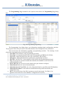
The Programming Log command in the Options menu shows the Programming Log dialog
box:
Fig. 36. Programming Log Dialog
The Programming Log dialog shows you information regarding board configuration activities.
The program is able to keep a track of all boards that have been configured in the workstation.
Each record stores the information regarding a programming operation. The meaning of each
field in the programming log record is the following:
Event Date: date and time of the programming operation;
Event Type: a string that identifies the result of programming (ERROR, SUCCESS);
Log Code: a short string that stores the code as inserted by the operator;
Description: additional information regarding the programming operation;
PNC/ELC: the PNC/ELC in the database record selected for programming the board;
Prog: the progressive insertion number that identifies the database record selected for
programming the board;
Service Kit Code: the service kit code related to the spare board to configure;
Naked Board Code: the code of the naked board;
Naked Board Code From TDS: the code of the naked board as specified in the TDS database;
Naked Board Firmware: is the firmware identification string in the board before the
configuration step;
MCF: code and revision of the PNC parameters stored in the board. For Fabric Care
appliances this field refers to the Machine Configuration File (MCF);
© 2011 Electrolux Italia S.p.A., All rights reserved
File: SidekickPC Manual (EN).pdf - Date: 11/05/2011
44
GTC – SOFTWARE DEVELOPMENT GROUP
CCF: code and revision of the base model parameters stored in the board. For Fabric Care
appliances it refers to the Cycle Configuration File (CCF);
Configured Board Firmware: firmware identification string in the board after the
configuration step;
Configured Board SN: serial number stored in the configured board, if any. The serial number
provides the date and time of the programming operation. It is a decimal number with the
following format:
YYMMDDHHmm
YY programming year modulus 40 (0..39 => 39=2039, 00=2040)
MM programming month (01..12 => 01= Janaury, 12=December)
DD programming day (01..31)
HH programming hour (00..23)
mm programming minute (00.59)
Example: 708081155 => this serial number indicates that the board has been programmed on
the 8th August 2007 at 11.55 AM.
Algorithm Name: the algorithm used for programming the board;
Communication Speed: the actual communication speed (baud rate) employed for board
programming;
Always Replace Firmware: when this flag is „true‟, the program always overwrites the
firmware even when the same firmware is already present in the target board;
Skip Verify After Programming: when this flag is „true‟, the program skips the check of the
operation after the board programming step.
Electrolux uses the programming log information both for collecting data that is useful for improving
the quality of products and for troubleshooting problems that you may experience while programming
electronic boards.
The software uploads the programming log to the central Sidekick server each time you execute an
Update operation. Programming log records are removed from your local PC after each update
operation if they are older than a specified period called “programming log retention time”. The
programming log retention time is typically 30 days.
© 2011 Electrolux Italia S.p.A., All rights reserved
File: SidekickPC Manual (EN).pdf - Date: 11/05/2011
45
GTC – SOFTWARE DEVELOPMENT GROUP
The Verify Only option allows you checking for the correct configuration of an already configured
board. When this option is set, SidekickPC verifies for proper configuration rather than programming
the board. This verification has 100% coverage of memory locations.
The Spare Board Label command in the Options menu shows the Label dialog box that allows the
activation of label printing after each board programming operation:
Fig. 37. Label Dialog
This dialog box allows you to enable/disable printing one or more labels after the successful
programming of each board. You can select how many identical labels to print for each board (the
number is limited to 10 labels).
With the Layout File field you define the label layout by means of external files (*.lbl).
According to the Print Options, the Print Sample command lets you preview or print a sample of the
selected label.
Press the Designer button if you want to enter the integrated label layout Designer. The Label
Designer enables you to modify an existing layout, to create a new one from the scratch, and to print
sample labels. This is a graphical editor that provides you with the full control over the label
appearance and contents. The Designer Metrics options allow you to specify the units of measure the
editor displays. The description of the layout Designer is outside the scope of this manual.
© 2011 Electrolux Italia S.p.A., All rights reserved
File: SidekickPC Manual (EN).pdf - Date: 11/05/2011
46
GTC – SOFTWARE DEVELOPMENT GROUP
The following is an example of label that you obtain:
Fig. 38. Label Example
As you can see, the label shows all identification data regarding the spare part, appliance model, and
database record used for the configuration:
973 914 791 101 00/4 is the Service Kit Code formatted for better readability;
00-01-132197270.000-132225610.000-W4A30111.000 indicates which database record has
been used for programming the spare part or upgrading the appliance configuration. Each
peace of information is separated from the following one by a hyphen. In the above example,
from left to right, the meaning of the various fields is the following one:
00: ELC field in the selected record. Sometimes the ELC field may be different from
the ELC that the Service Kit Code specifies;
01: Progressive Number field (Prog) in the selected record;
132197270.000: code and revision of the PNC parameters (machine configuration file
for Fabric Care appliances) programmed in the configured board;
132225610.000: code and revision of the base model parameters (cycle configuration
file for Fabric Care appliances) programmed in the configured board;
W4A30111.000: code and revision of the firmware programmed in the configured
board;
SN = 708081155 created with SidekickPC 1.0 shows the serial number stored in the
programmed board (if any). The meaning and format of the serial number has been previously
described in this chapter, in the section that deals with the programming log.
3.3.2. Printing Extended Information in the label
It is possible to print extended information in the label(s) that the software is able to print after each
board configuration.
Normally SidekickPC prints 3 lines of text.
By activating the Print Extended Information option in the Configuration Form, you can print
additional information that you can enter before programming each board. In this case, if you use the
proper label layout file (*.LBL), SidekickPC prints 4 lines of text.
This function is useful in all situations where the Service Kit Code is not used to identify the
configured spare board. This is true for some geographical areas outside Europe. In this case you can
manually specify the code to be printed on the label before programming each board.
© 2011 Electrolux Italia S.p.A., All rights reserved
File: SidekickPC Manual (EN).pdf - Date: 11/05/2011
47
GTC – SOFTWARE DEVELOPMENT GROUP
Fig. 39. Print Extended Information Option
If you quit SidekickPC and enter again, the software restores the state of the Print Extended Information
option from the previous session (this option is persistent).
Please remember to choose a proper label layout file. In order to print all information, it is necessary that
the selected label layout file refers to all 4 “Variables” that are available from within the Label Layout
Designer. The figure below highlights these variables:
Fig. 40. Label Layout Designer Variables
© 2011 Electrolux Italia S.p.A., All rights reserved
File: SidekickPC Manual (EN).pdf - Date: 11/05/2011
48
GTC – SOFTWARE DEVELOPMENT GROUP
The Part Number variable displays the part number as entered by the operator, as explained later in this
section.
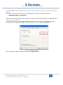
You can however start from one of the provided samples that support extended information:
1. SidekickPCExtInfo (77x20mm).lbl
2. SidekickPCExtInfo (77x25mm).lbl
Even if you start from one of the above samples, you must open the Layout Designer and adjust the label
settings to your actual printer.
You can do that by means of the Page Setup command that you can find in the Projects menu. This
command opens the Layout dialog box. This dialog box provides the Printer Selection tab:
Fig. 41. Printer Selection
Please remember to adjust margins and sizes in the Page Setup tab:
© 2011 Electrolux Italia S.p.A., All rights reserved
File: SidekickPC Manual (EN).pdf - Date: 11/05/2011
49
GTC – SOFTWARE DEVELOPMENT GROUP
Fig. 42. Page Setup
When this option is enabled, the board programming operation consists in one step more. This step occurs
just before the actual start of programming.
After you specify the quantity, you can enter also the name of the operator and the part number. This figure
shows the new text entry controls:
Fig. 43. Extended Information Controls
Both Operator’s Name and the Spare Part Code are options that are persistent between one session of
SidekickPC and the next one.
The software stores the last 5 settings of these options. You can choose the most recent values from the
corresponding list.
© 2011 Electrolux Italia S.p.A., All rights reserved
File: SidekickPC Manual (EN).pdf - Date: 11/05/2011
50
GTC – SOFTWARE DEVELOPMENT GROUP
The function is devised in order to minimize data insertion efforts for the operator. After you specify the
quantity, the focus moves automatically to the Spare Part Code, because it is more likely necessary to
change it with respect to the Operator‟s Name.
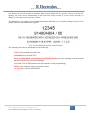
The following is an example of an extended information label that you can obtain starting from one of the
sample LBL files that SidekickPC supplies:
Fig. 44. Extended Information Label Example
The meaning of the above information is the following:
12345 is the manually inserted code;
914904904/00 is the PNC/ELC;
00-10-192560050.000-132535209.021-WBE20306.000 has the same meaning as in the normal
label described in the previous paragraph;
3/19/2009 5:10:43 PM indicates the date and time of the programming;
JOHN is the manually inserted operator‟s name;
1.1.2.0 is the version of SidekickPC.
© 2011 Electrolux Italia S.p.A., All rights reserved
File: SidekickPC Manual (EN).pdf - Date: 11/05/2011
51
GTC – SOFTWARE DEVELOPMENT GROUP
3.4. Identification Form
This is the form that appears you when press the Diagnostic button in the Startup form just
after the software successfully connects to the appliance and identifies it.
Fig. 45. Identification Form
The title bar of this form shows the Service Data set that has been selected for the appliance under test.
Service Data provide all information that is necessary for appliance diagnosis activities. Such
information is associated to families of products (platforms), not to single appliance models.
SidekickPC automatically associates the correct service data to use for diagnostic operations after it
properly identifies the appliance.
© 2011 Electrolux Italia S.p.A., All rights reserved
File: SidekickPC Manual (EN).pdf - Date: 11/05/2011
52
GTC – SOFTWARE DEVELOPMENT GROUP
This panel has three main groups of items.
The Appliance and Board Information group provides information about the current appliance
(platform, PNC/ELC if known, firmware ID, board type), its main features and configuration. Items in
orange background show appliance identification parameters. Items in white background show
appliance configuration data.
The History button opens the History Form. This button is not active if the database does not specify
any history reference information for the connected appliance.
The Monitor button opens the Monitor Form.
If you want a detailed description about each parameter in the Variable Description box, just select
the corresponding item in the above list.
© 2011 Electrolux Italia S.p.A., All rights reserved
File: SidekickPC Manual (EN).pdf - Date: 11/05/2011
53
GTC – SOFTWARE DEVELOPMENT GROUP
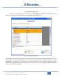
3.5. History Form
The History form provides information about the device usage history stored in the non-volatile
memory of the appliance.
Fig. 46. History Form
At the top of History form you can see a list that shows the history information. To see the detailed
description of each parameter in the Description textbox, just select the corresponding item in the
above list.
The actual items listed in the list depend on the appliance model and local database contents.
© 2011 Electrolux Italia S.p.A., All rights reserved
File: SidekickPC Manual (EN).pdf - Date: 11/05/2011
54
GTC – SOFTWARE DEVELOPMENT GROUP
3.6. Monitor Form
The Monitor form allows you watching appliance parameters and run the device tests.
Fig. 47. Monitor Form
At the top there is the Test selection list with all tests for the connected appliance. In order to start a
test, just select an item from the list and press the Start test button. When a test is in progress, the
same button becomes Stop test. In this case, you can use the button to stop the current test and,
usually, reset the appliance.
Test Description provides a short description about the selected test (if any).
In the middle of the Monitor form there is a list of input/output parameters that provide meaningful
information during the tests. In this list you can see the current values of the parameters. Please note
that SidekickPC displays all items whose values are outside the minimum/maximum limits in red. The
program usually updates these values every second. To see the detailed description of the variable in
the Variable Description field, just select it by clicking the corresponding item.
The Graph button allows you to enter the Graph form that shows you some parameters in graphical
form.
© 2011 Electrolux Italia S.p.A., All rights reserved
File: SidekickPC Manual (EN).pdf - Date: 11/05/2011
55
GTC – SOFTWARE DEVELOPMENT GROUP
The Reset Alarm button resets the last alarm stored in the non-volatile memory of the electronic
board. This command is only active if the local database defines a procedure to reset the last alarm.
Please note that if one alarm is currently still active, you cannot clear the last stored alarm as it will be
immediately set back again.
The Troubleshoot button shows the list of troubleshooting procedures defined by the local database
for the appliance under test (if any). For more information on the troubleshooting feature of
SidekickPC, please refer to the next paragraph.
The Digital I/O button allows you to enter the Digital I/O form that displays the current state of the
digital inputs and outputs in the appliance.
© 2011 Electrolux Italia S.p.A., All rights reserved
File: SidekickPC Manual (EN).pdf - Date: 11/05/2011
56
GTC – SOFTWARE DEVELOPMENT GROUP
3.6.1. Troubleshooting Wizard
If the local database defines troubleshooting procedures for the appliance under test, the
software is able to guide you step-by-step to the resolution of the fault, starting from the alarm code.
A troubleshooting procedure is a sequence of interactive dialog boxes.
When there is an alarm condition and the software detects that one troubleshooting procedure is
associated to that alarm, the Troubleshoot button in the Monitor form becomes red:
Fig. 48. Available Troubleshooting Procedure
© 2011 Electrolux Italia S.p.A., All rights reserved
File: SidekickPC Manual (EN).pdf - Date: 11/05/2011
57
GTC – SOFTWARE DEVELOPMENT GROUP
If you press the Troubleshoot button you can see the Troubleshooting List dialog:
Fig. 49. Troubleshooting List
This dialog shows the list of all available troubleshooting procedures in the database. All procedures
that are related to the current alarm condition (if any) are highlighted in red. In order to start the
Troubleshooting Wizard for a certain procedure, just select it from the list and press the Start
command.
© 2011 Electrolux Italia S.p.A., All rights reserved
File: SidekickPC Manual (EN).pdf - Date: 11/05/2011
58
GTC – SOFTWARE DEVELOPMENT GROUP
Each step consists in a dialog box that shows instructions and up to two images:
Fig. 50. Troubleshooting Wizard Step
The instructions provide information regarding the specific operation to execute. You should provide
a result to the wizard in terms of a Yes or No answer. The next step, if any, depends on the answer
you provide.
Troubleshooting steps either can be only manual or can involve the interaction with the electronic
board. The management of such interaction is completely automatic for the end user.
© 2011 Electrolux Italia S.p.A., All rights reserved
File: SidekickPC Manual (EN).pdf - Date: 11/05/2011
59
GTC – SOFTWARE DEVELOPMENT GROUP
3.7. Graph Form
The Graph form allows you to see the evolution of the appliance parameters in graphical form.
Fig. 51. Graph Form
To see the graphical representation of one appliance variable, you should choose it from the Variable
selection field at the top of Graph Form. Click with the mouse the selection button ( ) and choose
the variable name. The detailed description of the variable appears in the Variable description field.
In the Current Value field you can see the present value of the selected parameter.
The Maximum Display Interval (min) control allows you to select the display width of the graph.
The default interval is 1 min, but you can change it from 1 minute up to 5 hours. For each variable, the
program reads a new data sample from the appliance every 1 second.
The Print button allows you to create a hardcopy of the current graph.
The Export Graph button allows you to export the current graph in one of the following image
formats: BMP, GIF, JPG, PNG, and TIFF.
© 2011 Electrolux Italia S.p.A., All rights reserved
File: SidekickPC Manual (EN).pdf - Date: 11/05/2011
60
GTC – SOFTWARE DEVELOPMENT GROUP
3.8. Digital I/O Form
The Digital I/O form displays the current state of the digital inputs and outputs in the appliance.
Fig. 52. Digital I/O Form
You can see a list of the digital inputs and outputs states that are meaningful during the diagnostic
procedures. The program updates these values every second.
To see the detailed description of each parameter in the Description, just select the corresponding item
in the list.
© 2011 Electrolux Italia S.p.A., All rights reserved
File: SidekickPC Manual (EN).pdf - Date: 11/05/2011
61
GTC – SOFTWARE DEVELOPMENT GROUP
3.9. Appliance Information
If in the Start page you select the Appliance Information command, a dialog box asks you to
insert the PNC/ELC of the appliance. You can insert optional blank and slash (/) characters in order to
increase the readability of the string.
By pressing the
button, a list containing all the PNC/ELC Codes stored in the local database
appears. You can select one item from the list and you have the possibility to restrict the selection list
by filling the Starts with field.
Fig. 53. Specify PNC/ELC Form
After you have inserted the code and pressed the OK button, the software shows you a form that
provides some information about the appliance:
Fig. 54. Identification and Configuration Form
© 2011 Electrolux Italia S.p.A., All rights reserved
File: SidekickPC Manual (EN).pdf - Date: 11/05/2011
62
GTC – SOFTWARE DEVELOPMENT GROUP
This form provides the following information:
Board Name: name of the electronic board;
Platform: name of the electronic platform;
Spare Board Code: spare part number of the not configured board;
Factory Code: a code that identifies the factory;
Service Kit Code: spare part number of the configured board;
Firmware Code: a code that identifies the firmware;
Firmware Revision: firmware revision;
PNC Parameters Code: a code that identifies the configuration parameters;
PNC Parameter Revision: configuration parameters revision;
Base Model Parameters Code: a code that identifies the basic configuration parameters;
Base Model Parameters Revision: basic configuration parameters revision.
If you click the
button near the record related to the spare board, the Spare Board
Information form appears (please refer to the corresponding paragraph in this manual for more
information about this form).
If you click the Test And Alarms button the following form appears:
© 2011 Electrolux Italia S.p.A., All rights reserved
File: SidekickPC Manual (EN).pdf - Date: 11/05/2011
63
GTC – SOFTWARE DEVELOPMENT GROUP
Fig. 55. Test And Alarm Form
This form shows a drop-down control named Test containing a test selection list, by selecting a test
you can see the corresponding description into the Test Description textbox.
Below there is another drop-down control named Alarm containing a list of all alarm codes, by
selecting one alarm code the corresponding description is shown in the Alarm Description textbox.
The Troubleshooting button allows you to select and execute troubleshooting procedures in off-line
mode. The troubleshooting button is enabled only if there is at least one procedure available. If you
press this button you can see the Troubleshooting List dialog:
© 2011 Electrolux Italia S.p.A., All rights reserved
File: SidekickPC Manual (EN).pdf - Date: 11/05/2011
64
GTC – SOFTWARE DEVELOPMENT GROUP
Fig. 56. Troubleshooting List
This dialog shows the list of all available troubleshooting procedures in the database.
By changing the Alarm in the alarm selection list, the corresponding procedure in Troubleshooting List
is highlighted In order to start the Troubleshooting Wizard for a certain procedure just select it from
the list and press Start button.
The function is very similar to the troubleshooting procedure executed while you are diagnosing an
appliance that is really connected. The only difference is that in this case SidekickPC does not send
any commands to the appliance.
© 2011 Electrolux Italia S.p.A., All rights reserved
File: SidekickPC Manual (EN).pdf - Date: 11/05/2011
65
GTC – SOFTWARE DEVELOPMENT GROUP
4. APPENDIX
This appendix describes the manual software installation. Sometimes you may need to execute
a manual installation, for example in order to override default setup options or for investigating setup
problems.
4.1. MANUAL SOFTWARE INSTALLATION
This paragraph describes the sequence of steps in a typical setup procedure on a PC running
Windows XP without any additional installed software. Setup steps may however vary depending on
the actual operating system and software configuration of the PC.
You must log on as full Administrator in order to make the installation of the software.
4.1.1. SidekickPC Setup
1. Run the SETUP.EXE program that is present in the root folder of the distribution CD.
2. If the .NET Framework 2.0 is not installed, SETUP asks you to install it. Just press
Accept to go on:
Fig. 57. Install .NET Framework 2.0
© 2011 Electrolux Italia S.p.A., All rights reserved
File: SidekickPC Manual (EN).pdf - Date: 11/05/2011
66
GTC – SOFTWARE DEVELOPMENT GROUP
3. If the WSE 3.0 Runtime is not installed, SETUP asks you to install it. Just press Accept
to go on:
Fig. 58. Install WSE 3.0 Runtime
4. If Windows Installer 3.1 is not installed, SETUP asks you to install it. Just press Accept
to go on:
Fig. 59. Install Windows Installer 3.1
© 2011 Electrolux Italia S.p.A., All rights reserved
File: SidekickPC Manual (EN).pdf - Date: 11/05/2011
67
GTC – SOFTWARE DEVELOPMENT GROUP
5. After installing Windows Installer 3.1 prerequisites, you are asked to reboot your PC.
Fig. 60. Reboot the system
6. Reboot the PC, log on as full Administrator and, if necessary, run again SETUP.EXE. If
there is no SQL Server 2005 installed instance, you immediately get an error message like
the following one. Otherwise skip to step 17.
Fig. 61. SQL Server 2005 Required
© 2011 Electrolux Italia S.p.A., All rights reserved
File: SidekickPC Manual (EN).pdf - Date: 11/05/2011
68
GTC – SOFTWARE DEVELOPMENT GROUP
Press OK to quit SETUP without completing the installation:
Fig. 62. Installation Incomplete
7. Run the SQLEXPR.EXE program located in the SqlExpress folder in the distribution
CD and accept the license agreement. This program checks and installs prerequisites. At
the end press Next:
Fig. 63. SQL Server Express Setup – Prerequisites Installation
© 2011 Electrolux Italia S.p.A., All rights reserved
File: SidekickPC Manual (EN).pdf - Date: 11/05/2011
69
GTC – SOFTWARE DEVELOPMENT GROUP
8. After the System Configuration Check press Next:
Fig. 64. SQL Server Express Setup – System Configuration Check
© 2011 Electrolux Italia S.p.A., All rights reserved
File: SidekickPC Manual (EN).pdf - Date: 11/05/2011
70
GTC – SOFTWARE DEVELOPMENT GROUP
9. After entering registration data press Next:
Fig. 65. SQL Server Express Setup – Registration
10. You can keep the default features. Then press Next:
Fig. 66. SQL Server Express Setup – Feature Selection
© 2011 Electrolux Italia S.p.A., All rights reserved
File: SidekickPC Manual (EN).pdf - Date: 11/05/2011
71
GTC – SOFTWARE DEVELOPMENT GROUP
11. You can keep the default for Authentication Mode (the setup program will later
automatically change this setting to Mixed Mode):
Fig. 67. SQL Server Express Setup – Authentication Mode
12. Important: select both checkboxes in the Configuration Options window and press Next.
Fig. 68. SQL Server Express Setup – Configuration Options
© 2011 Electrolux Italia S.p.A., All rights reserved
File: SidekickPC Manual (EN).pdf - Date: 11/05/2011
72
GTC – SOFTWARE DEVELOPMENT GROUP
13. Keep the default options for Report Settings, then press Next:
Fig. 69. SQL Server Express Setup – Report Settings
14. SQL Server 2005 is ready to install. Press Install:
Fig. 70. SQL Server Express Setup – Ready to install
© 2011 Electrolux Italia S.p.A., All rights reserved
File: SidekickPC Manual (EN).pdf - Date: 11/05/2011
73
GTC – SOFTWARE DEVELOPMENT GROUP
15. Wait until the end of SQL Server setup, then press Next:
Fig. 71. SQL Server Express Setup – End of Setup
16. Just press Finish to complete the setup procedure:
Fig. 72. SQL Server Express Setup – Optional Steps
© 2011 Electrolux Italia S.p.A., All rights reserved
File: SidekickPC Manual (EN).pdf - Date: 11/05/2011
74
GTC – SOFTWARE DEVELOPMENT GROUP
17. If you have just installed SQL Server 2005 Express, run again SETUP.EXE. You are
now prompted to choose the installation folder. Keep the default settings unless strictly
necessary. Please remember that you cannot specify special folders like “C:\Program
Files”,
“C:\Documents
and
Settings\All
Users\Application
Data”,
or
“C:\Windows\System32”. If you do it, the setup will show you an error message and
rollback the entire process. This limitation is due to a compatibility issue related to the
Microsoft Vista operating system:
Fig. 73. Select Installation Folder
© 2011 Electrolux Italia S.p.A., All rights reserved
File: SidekickPC Manual (EN).pdf - Date: 11/05/2011
75
GTC – SOFTWARE DEVELOPMENT GROUP
18. SETUP asks you to choose the settings of the Database that it is going to automatically
create. It is possible to specify a database and login created with a previous installation of
the software. Keep the default settings unless strictly necessary. Data Source identifies
the SQL Server instance that will hold the local database. Database is the name of the
local database. User ID and Password are the credential of the login to the local
database. Please remember that, by default, SidekickPC uses “Mixed Authentication” to
connect to the local database:
Fig. 74. Database Settings
19. Specify the URL and credentials for the Web Services Settings that the application will
use to download data updates, if you already know them. For Username and Password
you should use the login information you have been given with an automatic e-mail
notification when your account was created. These are the same credentials that you use
to access to the reserved area in the Sidekick Portal:
Fig. 75. Web Service Settings
© 2011 Electrolux Italia S.p.A., All rights reserved
File: SidekickPC Manual (EN).pdf - Date: 11/05/2011
76
GTC – SOFTWARE DEVELOPMENT GROUP
20. Enter your license number in the Activation Settings window, if you already know it. You
should use the license number you have been given with an automatic e-mail notification
when your account was created:
Fig. 76. Activation Settings
21. Confirm the installation and wait for the completion of the process. If any errors occur
during the setup, an installation log appears. Otherwise no other dialog appears, except
the final one.
22. SETUP finally completes. Just press Close to end the process:
Fig. 77. Installation Complete
© 2011 Electrolux Italia S.p.A., All rights reserved
File: SidekickPC Manual (EN).pdf - Date: 11/05/2011
77
GTC – SOFTWARE DEVELOPMENT GROUP
4.1.2. SQL Server Management Studio Express Setup
This section describes the optional installation of SQL Server Management Studio Express.
The installation of this software is only necessary for software troubleshooting purposes. This is a tool
for the administration of the local database, only necessary for software support activities.
In most cases you can simply skip this section.
1. Run the SQLServer2005_SSMEE.msi installer located in the Extra\Microsoft SQL
Server Management Studio Express folder in the distribution CD. In the welcome
dialog press Next:
Fig. 78. SQL Server MS Express Setup - Welcome
2. Accept the license agreement, then press Next:
Fig. 79. SQL Server MS Express Setup – License Agreement
© 2011 Electrolux Italia S.p.A., All rights reserved
File: SidekickPC Manual (EN).pdf - Date: 11/05/2011
78
GTC – SOFTWARE DEVELOPMENT GROUP
3. Insert registration information, then press Next:
Fig. 80. SQL Server MS Express Setup – Registration
4. You can select the default features. Then press Next:
Fig. 81. SQL Server MS Express Setup – Feature Selection
© 2011 Electrolux Italia S.p.A., All rights reserved
File: SidekickPC Manual (EN).pdf - Date: 11/05/2011
79
GTC – SOFTWARE DEVELOPMENT GROUP
5. SQL Server Management Studio Express is ready to install. Press Install:
Fig. 82. SQL Server MS Express Setup – Ready to Install
6. Wait until the end of setup, then press Finish:
Fig. 83. SQL Server MS Express Setup – End
© 2011 Electrolux Italia S.p.A., All rights reserved
File: SidekickPC Manual (EN).pdf - Date: 11/05/2011
80
GTC – SOFTWARE DEVELOPMENT GROUP
4.2. TROUBLESHOOTING SETUP PROBLEMS
In this section you can find additional information that you may need in order to solve
installation problems.
4.2.1. Manual installation of prerequisites
Under certain circumstances, the Sidekick setup procedures may not be able to detect the
absence of one or more software prerequisites. In this case you can install them manually prior
running the manual or automatic setup.
In case of need, you should manually install the prerequisites in the following order:
1. Microsoft Windows Installer 3.1. Run the \WindowsInstaller3_1WindowsInstallerKB893803-v2-x86.exe file.
2. MDAC 2.8. Run the \MDAC28\mdac_typ.exe file.
3. Microsoft .NET Framework 2.0. Under Windows XP or Vista 64-bit run the
\dotnetfx\64-bit\NetFx64.exe file. Under Windows XP or Vista 32-bit run the
\dotnetfx\32-bit\dotnetfx.exe file.
4. Microsoft WSE 3.0. Run the \WSE3_0\Microsoft WSE 3.0 Runtime.msi file
5. Microsoft SQL Server Express Edition 2005 SP2. Run the
\SqlExpress\SQLEXPR.EXE file. At this point the SQL Server setup program may
detect that Microsoft Internet Explorer 6.0 SP1 is missing. In this case you must stop the
installation and run \Extra\IE6Setup\ie6setup.exe, prior installing SQL Server.
6. SQL Server Management Studio Express (optional). Run \Extra\Microsoft SQL
Server Management Studio Express\SQLServer2005_SSMSEE.msi.
4.2.2. SQL Server installation problems
Under certain circumstances, the SQLEXPR.EXE program may encounter problems depending
on the actual configuration of the PC and of the network. These problems are outside the control of
Electrolux.
In case of problems you can find in the internet plenty of information regarding tips and workarounds
related to setup issues. You should in particular refer to Microsoft forums dealing with the matter.
Experience collected so far by CTI has revealed a few problems regarding the setup of SQL Server
2005 Express Edition. You can find the solution for these problems here:
http://sidekick.electrolux.com/SidekickPortal/UsersReservedArea/DownloadDetails.aspx?ContentID=
ApplicationNote3
© 2011 Electrolux Italia S.p.A., All rights reserved
File: SidekickPC Manual (EN).pdf - Date: 11/05/2011
81