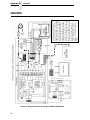
1
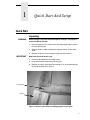
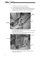
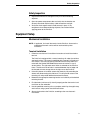
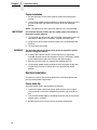
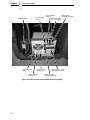
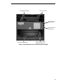
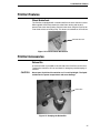
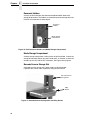
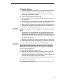
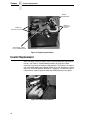
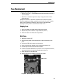
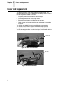
PrintCart
User’s Manual
PrintCart
User’s Manual
251755-001F
Trademarks
Printronix is a registered trademark of Printronix, Inc.
All other trademarks are the property of their respective owners.
Product Warranty
Printronix, Inc. makes no representations or warranties of any kind regarding
this material, including, but not limited to, implied warranties of
merchantability and fitness for a particular purpose. Printronix, Inc. shall not
be held responsible for errors contained herein or any omissions from this
material or for any damages, whether direct, indirect, incidental or
consequential, in connection with the furnishing, distribution, performance or
use of this material. The information in this manual is subject to change
without notice.
Communication Notices
This device complies with Part 15 of the FCC Rules. Operation is subject to
the following two conditions: (1) this device may not cause harmful
interference, and (2) This device must accept any interference received,
including interference that may cause undesired operation.
This Class A digital apparatus complies with Canadian ICES-003.
Cet appareil numérique de la Class A est conform à la norme NMB-003 du
Canada.
Emergency Disconnect Procedure
In an electrical emergency disconnect the AC input line cord from any
external power source and disconnect the AC output line cords from any
equipment powered by the cart.
Unterbrechung der Stromversorgung im Notfall
Bei einem Notfall im Bereich der Elektro-Installation die
Spannungsversorgungskabel von allen externen Spannungsquellen sowie
die Spannungsversorgungskabel von allen über das Cart mit Spannung
versorgten Geräten abziehen.
Notice of Copyright
This document contains proprietary information protected by copyright. No
part of this document may be reproduced, copied, translated or incorporated
in any other material in any form or by any means, whether manual, graphic,
electronic, mechanical or otherwise, without the prior written consent of
Printronix, Inc.
Copyright © 2007, 2010 Printronix, Inc. All rights reserved.
Specifications subject to change without notice.
Table of Contents
1 Quick Start And Setup .......................................... 7
Quick Start ............................................................................................. 7
Unpacking ....................................................................................... 7
Safety Inspection............................................................................. 9
Equipment Setup ................................................................................... 9
Mechanical Installation .................................................................... 9
Electrical Installation ..................................................................... 10
Startup ................................................................................................. 11
Operating Limitations........................................................................... 12
2 PrintCart.............................................................. 15
Overview.............................................................................................. 15
PrintCart Layout................................................................................... 16
3 Operation ............................................................ 21
Line Power Operation .......................................................................... 21
Battery Power Operation ..................................................................... 23
PrintCart Operating Duration......................................................... 23
Indicator Panel..................................................................................... 24
Gaining Access To The Printer............................................................ 26
Slide The Tray To Service Position ............................................... 26
Load Media Or Ribbon .................................................................. 26
PrintCart Features ............................................................................... 27
PrintCart Accessories .......................................................................... 27
4 Troubleshooting .................................................. 31
Safety................................................................................................... 31
PrintCart Safety Features .................................................................... 32
Troubleshooting Guide ........................................................................ 33
5 Maintenance........................................................ 37
Power Equipment Access.................................................................... 37
Serviceability Inspection ...................................................................... 40
Battery Replacement ........................................................................... 40
Inverter Replacement .......................................................................... 42
Fuse Replacement............................................................................... 43
Display Fuse ................................................................................. 43
Main Fuse ..................................................................................... 43
Power Cord Replacement.................................................................... 44
Wheel Replacement ............................................................................ 45
Caster Wheels............................................................................... 45
Fixed Wheels ................................................................................ 45
Hand Grip Replacement ...................................................................... 46
A Specifications ...................................................... 47
Physical Specifications ........................................................................ 47
Electrical Specifications ....................................................................... 48
B Wiring Schematics .............................................. 49
120V/60Hz ........................................................................................... 49
230V/50Hz ........................................................................................... 50
C Spare Parts ......................................................... 51
D Glossary .............................................................. 53
E Contact Information............................................. 55
Printronix Customer Support Center.................................................... 55
Printronix Supplies Department ........................................................... 55
Corporate Offices................................................................................. 56
1
Quick Start And Setup
Quick Start
Unpacking
WARNING
Dismounting the cart from the pallet requires strength. Two people is
recommended for the task.
1. Place the pallet on a flat, level surface, leaving enough room to roll the
PrintCart off the pallet.
2. Remove the two cardboard protective shipping sleeves and set them
aside.
3. Remove the plastic wrap and shipping bag from the PrintCart.
IMPORTANT
Make sure the caster brake is set.
4. Cut the bands holding the unloading ramps.
5. Lift and remove the ramps off the locating pins.
6. Reverse the ramps and engage the locating pin in the angled blocks on
the end of the pallet. See Figure 1.
Locating Pin
Ramp
Figure 1. Reversing the Ramps and Engaging the Locating Pin
7
Chapter
1
Quick Start
7. If necessary set the caster brake on the PrintCart.
8. Cut the shipping restraint tie wraps on all turnbuckles.
9. Insert a screwdriver through the center of each turnbuckle housing and
loosen the turnbuckle until you can remove the hook from the eyelet.
10. Unhook the opposite end from the PrintCart frame. See Figure 2.
Shipping
Restraint
Hook
Turnbuckle
Housing
Figure 2. Loosening the Turnbuckle from its Housing
11. On the opposite side of the PrintCart, repeat steps 9 and 10 to completely
disengage the shipping restraints.
12. Release the caster brake. Grasp the hand grips and pull the PrintCart
down the unload ramps to the work surface.
Hand Grip
PrintCart
Ramp
Figure 3. Moving the PrintCart to the Work Surface
13. Replace the unloading ramps on the pallet and store the pallet and
turnbuckles for future re-use.
8
Safety Inspection
Safety Inspection
1. Inspect the PrintCart for damage that may have occurred during
shipment.
2. Open the power compartment door and verify that the batteries are
securely restrained and the battery cable connections are tight.
3. Verify that the charger/inverter is held securely in place. If any
components have loosened during shipment, secure them before
applying power to the PrintCart.
Equipment Setup
Mechanical Installation
NOTE: If applicable, first install the terminal to the PrintCart. Access to the
underside of the work surface will be restricted after printer
installation.
Terminal Installation
1. Follow the manufacturer’s installation instructions to install the wireless
terminal.
The PrintCart is equipped with a central mounting rail under the stainless
steel work surface. This mount is predrilled with 2 rows of 5/16” holes on 1
inch centers. The size and spacing coincides with the hole pattern that
mates with the Symbol VRC 8900 series terminals bracket; it may fit
several others. The right-most row of holes is centered on the PrintCart
frame. The left-most row of holes is centered between the left edge and
the barcode scanner storage slot on the right rear of the PrintCart.
2. If the utility drawer is installed, remove the drawer by fully extending the
drawer and disconnecting the slide latch. This will provide access to the
mounting rail and provide additional overhead clearance.
3. Determine the appropriate mounting location and suitability of the desired
mounting bracket.
4. Find the holes (minimum of 2) that will properly position the terminal and
mark them on the underside.
5. Use the predrilled mounting rail as a template and drill up through the top
work surface using a power hand drill from below.
6. Secure the bracket to the PrintCart according to the manufacturer’s
instructions.
9
Chapter
1
Equipment Setup
Printer Installation
1. Set the wheel lock on the caster wheel to prevent the PrintCart from
moving.
2. Lift the spring loaded handle located on the side of the slide out tray and
pull the tray out over the side of the PrintCart to the fully extended
position.
NOTE: The slide out tray clicks into place when the tray is fully extended.
IMPORTANT
For Printronix thermal printers, the four rubber pads on the bottom of
the printer must be removed.
3. Tip the printer onto the left side (side with power compartment cover) and
unscrew the rubber pads. If necessary, use pliers to improve grip.
4. Install the four black rubber vibration mounts that are provided with the
PrintCart.
5. Tip the printer back upright.
WARNING
The next step requires two people; one person to support the printer,
the other to align the mounts.
6. Carefully lift the printer and set it on the slide out tray, aligning the
threaded vibration mounts with the holes in the tray. The printer’s control
panel should face the end of the PrintCart with the hand grips.
7. Secure the printer to the tray using the four supplied lock nuts.
8. Lift the spring loaded handle and slide the tray back under the top work
surface of the PrintCart. It should click into a retracted and locked
position.
Electrical Installation
The electrical cable for the PrintCart equipment is routed through the right
rear leg into the power compartment.
Printer Hook-Up
The printer power cable is preinstalled in the PrintCart.
1. Connect the power cable to the printer. Make sure the cord is slightly
slack to provide a small service loop during movement of the slide out
tray.
2. Test the service loop length by extending the printer shelf and verify that
enough slack is available.
3. Bundle and secure any excess cord in the power compartment.
10
Electrical Installation
Terminal Hook-Up
1. Install the power supply for the terminal in the pocket provided behind the
two slot notebook bin. See Figure 4.
Pocket
Two Slot
Notebook Bin
Figure 4. Installing Power to the Terminal
If this accessory is not included with the PrintCart:
2. Locate power supply in the power compartment to the left of the inverter.
3. Connect an AC power cord to the power supply and connect it to the
remaining receptacle by routing it down through the right rear leg into the
inverter compartment.
4. Bundle and secure any excess cord.
5. Route the DC power cable from the terminal to the power supply and
secure all excess cable length (terminal P/S pocket behind the letter bin).
Startup
Make sure all PrintCart equipment has been installed and power cords have
been routed and connected to the inverter.
1. Check that the equipment power switches are in the OFF (0) position.
The PrintCart is now prepared for start-up.
2. Open the power compartment front door (hand grip end) and connect the
main inverter power/battery cable to the connector on the battery
subpallet.
3. Open the power compartment rear door and locate the inverter operating
switch on the upper-right of the inverter.
4. Slide the switch left to the “AUTO/INVERT” position. The inverter will
begin producing power as indicated by the yellow mode indicator on the
inverter.
11
Chapter
1
Operating Limitations
5. Close and latch the rear door.
Inverter and battery status are indicated on the LED display panel located on
the front of the PrintCart adjacent to the hand grips. The batteries in a new
PrintCart arrives nearly fully charged. Battery state of charge “gas gauge”
shows all LED’s lit, (2 red, 2 yellow, and 2 green). If all of the battery status
LED’s are not lilt, charge the PrintCart prior to use.
Power is available when the inverter is in the auto position; the equipment
may now be switched on. If the connected equipment does not receive power,
perform the following:
•
120V units
Examine the GFCI duplex outlet to the left of the inverter. If the trip
indicator lamp located on the right side of the GFCI is illuminated, the
GFCI has faulted. Reset the GFCI by depressing the RESET button
between the two plugs.
•
230V units
Examine the “Load C/B” (load circuit breaker) located above the inverter
output receptacles. If it extends beyond the mounting more that a couple
of millimeters, it has faulted. Reset the load circuit breaker by pressing it
in.
Close and latch the power compartment door.
Operating Limitations
When the cart is not in service, leave it plugged in to maintain battery charge.
Otherwise, charge the cart battery every 90 days.
CAUTION
Recharge the batteries as soon as possible after use. Failure to quickly
recharge batteries can result in permanent battery damage. Batteries
left in a discharged state for extended periods may be so damaged that
they will not accept a charge and recharging them could be dangerous.
Any attempt to recharge partially discharged batteries left for an
extended time requires frequent supervision to ensure that venting or
excessive heating does not occur.
Do not charge a fully discharged battery at a rate greater than 1/10 of the
amp-hour capacity. This cart is equipped with fail safe controls to
prevent full discharge. If the batteries become fully discharged, possibly
due to long term inactivity, switch the inverter/charger to slow charging
mode to revive them. Slow charging prevents further damage to the
battery and reduces the risk of battery out-gassing or destructive
heating if the battery is damaged beyond recovery.
12
Electrical Installation
120V/60Hz Models
Eight switches are located on the top center of the RV750ULHW inverter/
charger front panel. The far left switch is for charge rate. The down (normal)
position is fast (45A) charge; the up position is slow (11A) charge. Use the UP
position to recharge fully discharged batteries. If the batteries accept a full
charge without excessive heating or out-gassing, the capacity selector can be
retuned to the full (down) setting.
230V/50Hz Models
A red button labeled “Sleeping Mode” is located on the right side of the
charger (blue device at the bottom of the power module). Depressing this
button reduces the charge rate to approximately 1/3 the normal rate. If the
batteries accept a full charge without excessive heating or out-gassing, the
sleep mode button can be retuned to the full or out position.
WARNING
If the batteries become excessively hot or emit a detectable odor, the
batteries are damaged beyond repair and are dangerous to use. Stop
charging immediately. Remove the batteries from service and dispose
of them according to local regulations.
Do not charge the batteries at a rate greater than 1/4 of the amp-hour
capacity. For example, a 100 amp-hour battery should be charged no faster
than 25 amps (or a pair of 100 amp-hour batteries no faster than 50A).
The charger on this cart provides the maximum recommended charge rate for
the batteries with which it is equipped.
CAUTION
Do not use additional or larger chargers to speed recharging.
Permanent battery damage will occur and the potential for catastrophic
failure is high.
Before connecting or disconnecting the batteries, turn off battery powered
electrical equipment and disconnect both the main DC disconnect and display
power cable.
Make sure that battery terminal covers are in place to prevent accidental
shorts between the battery and surrounding frame or equipment.
Use insulated tools to service any power connections that cannot be
disconnected from battery power.
13
Chapter
14
1
Operating Limitations
2
PrintCart
Overview
The PrintCart is a wireless, cordless work platform capable of transporting
several pieces of electrically powered equipment to a work site. On site, the
PrintCart can operate indefinitely on line power or for an extended period of
time (depending on equipment) on battery power. The PrintCart is designed to
support continuous operation of all connected equipment without shutting
down.
The PrintCart contains three separate levels:
Bottom Level
The bottom level is the power compartment, which houses the power storage,
power conversion equipment, and the electrical safety devices that ensure
safe PrintCart operation.
Middle Level
The middle level contains the printer and storage of materials and waste. The
printer shelf is mounted on slides that permit a thermal printer to extend out
the right side of the PrintCart for service. To the left of the printer shelf is a
refuse bin, document holders, and a media storage bin. Above the printer is a
utility drawer.
Top Level
The top level has a stainless steel work area which supports electronic
wireless terminal mounting and installation of a barcode scanner storage slot.
The power compartment is enclosed and latched with a mechanism that
requires a tool to open to prevent incidental access. It contains two sealed
lead acid batteries for electricity storage. Power is provided by a combination
device called an inverter/charger. Inversion is the process of using the 12 volt
direct current stored in the batteries and converting it to a suitable alternating
current at a voltage and frequency for operating equipment mounted on the
PrintCart. The PrintCart operating voltage can be 120 volts AC @ 60 Hertz
(North American standard) or 230 volts AC at 50 Hertz (European standard).
Operating voltage is specified at the time of order and can be changed by
swapping out the Power Equipment Subpallet (PESP).
15
Chapter
2
PrintCart Layout
The battery charge function is performed in the inverter/charger. When AC
line power is applied, the inverter charger automatically transfers (switches)
power directly to the PrintCart equipment and begins charging the batteries.
The charger provides power to the batteries in three separate stages to
optimize the storage capacity and battery life.
The PrintCart can support multiple pieces of electrical equipment. The
primary intent is to support one Printronix four inch or six inch thermal printer
on the printer shelf. The PrintCart includes an installation kit consisting of four
bolt-on shock mount isolators for securing the printer to the shelf.
The top work area can be used for any application but is intended for use with
a wireless terminal and barcode scanner. The barcode scanner storage bin
can be mounted on the right rear of the work surface. On the front left is a
display panel with integral controller. The display panel has a set of battery
charge status LEDs that report the battery state of charge. It also has a set of
stop light LEDs that display the inverter/charger mode status.
Additionally, there is an alarm to alert the user to recharge the batteries. The
built-in controller monitors power consumption and signals the user when the
batteries need recharging. The controller provides progressive alarms to the
user, indicating that there is a warning period to permit completion of the
current task, progressing to a shorter shutdown period. This indicates that the
PrintCart will soon enter automatic shutdown if not connected to line power for
recharging.
PrintCart Layout
Status Display
Barcode Scanner
Storage Slot
Hand Grip (2)
Stainless Steel
Work Surface
Printer (not included)
Battery Access Door
Brake/Locking
Caster
Figure 5. Front Right View of the PrintCart
16
Document Holder (2)
Refuse Bin
Rear Loop-Handle and
Terminal Protector
Printer (not included)
Power Equipment
Compartment
Media/Ribbon
Storage
Power Compartment
Latch
Power Cord
8” Fixed Wheel (2)
Figure 6. Rear Left View of the PrintCart
Power Status
Indicator
Battery Status
Indicator
Figure 7. Display Panel
17
Chapter
2
PrintCart Layout
Inverter Setup
Switches
AC Output GFCI
Grounding Lug
(AC)
Inverter Display
Main Inverter
Indicator
Power/Mode Switch
External Display
Panel Connector
Positive Battery
Cable Input
Negative Battery
Cable Input
Main AC Input Power
Circuit Breaker (15A)
Battery Charger
Circuit Breaker (8A)
Figure 8. Power Pallet Features and Safety Devices (120V)
18
Cart Equipment Outlet
AC Power Inverter
AC Input Circuit
Breaker (8A)
AC Output Circuit
Breaker (5A)
Battery Charger Module
Battery Charger Sleep
Mode Button Location
Figure 9. Power Module Features and Safety Devices (230V)
19
Chapter
20
2
PrintCart Layout
3
Operation
Line Power Operation
When the line cord is connected to a wall receptacle, AC line power is
transferred by an Automatic Transfer Switch (ATS) directly to the cart
equipment. There is a short delay in applying line power (approximately 20
seconds for the 120V and 8 seconds for the 230V) to permit the plug to be
secured in the receptacle. The transfer happens quickly so operation of the
connected equipment is not interrupted.
NOTE: There is no need to power the PrintCart equipment off when either
connecting or disconnecting from line power.
When operating on AC line power, the green mode indicator (line power) on
the display illuminates.
The charger begins to charge the batteries after the ATS transfers line power
to the PrintCart. The charger is a three stage device designed for optimal
battery charging.
•
Stage 1 – when the charging cycle starts, the charger provides maximum
rated charge until the battery reaches approximately 75% capacity.
Completely charging the battery before reusing the PrintCart provides
good PrintCart longevity.
•
Stage 2 – the charge rate is reduced from full capacity to 10% capacity to
charge the last 25% of the battery. Completion of second stage charging
only slightly improves short term operating longevity but greatly improves
long term battery life.
•
Stage 3 – when the battery is fully charged, a trickle charge is applied to
keep the battery at full capacity.
The time required for a recharge depends on the state of discharge, the size
of the battery bank, and the charger’s capacity. The PrintCart controller
prevents the batteries from discharging more than 70% of their energy (Depth
of Discharge or DoD); this reduces the rate of permanent battery damage.
Maximum recharge times for the PrintCart are listed in Table 1 on page 22.
When the charging begins, the charger will indicate battery state improvement
through the State of Charge (SoC) LEDs, but displays differently between the
120V and 230V carts.
21
Chapter
3
Line Power Operation
•
120V – as charging progresses, yelow and green bars illuminate
individually with each 10-15% increase in charge state.
•
230V – the two red bars light when the charger is in Stage 1 (30-75%
charge). When the charger enters Stage 2 (76-98% charge), the two
yellow lights also illuminate. The two green lights illuminate together when
the charger enters Stage 3 (greater than 98% charge). When all SoC
lamps are illuminated, the PrintCart is fully charged.
When battery power is available to the PrintCart, the Battery Powered
mode indicator (yellow) illuminates. When the PrintCart is connected via
line power, the Line Powered mode indicator (green) illuminates.
Make sure the source of AC power is through a modern 3-prong grounded
outlet and is a reliable service capable of delivering the required current.
Normal and maximum current specifications are listed in Appendix A on
page 47. Table 1 on page 22 shows the maximum recharge time.
Table 1. PrintCart Charge Time
Battery Type
2x100 Ah
Maximum (hrs)
Typical (hrs)
4.7
3.7
The line cord design uses a short PrintCart cord connected to an extension
cord. The two are connected together inside a cord wrapping device. This
method provides an easy, user level repair to encourage maintenance. The
cord can be replaced with a variety of cords as long as they meet the original
specification and are not longer than 25 feet. See “Spare Parts” on page 51
for cord requirements.
IMPORTANT
22
Using a cord or series of cords longer than 25 feet may result in power
loss. This could affect operation of either the PrintCart equipment or
power system.
PrintCart Operating Duration
Battery Power Operation
When the PrintCart is unplugged from the AC outlet, the power system
automatically switches equipment to inverter power via the automatic transfer
switch.
NOTE: The PrintCart equipment does not have to be turned off and there will
be no significant power interruption to the equipment.
The Battery Powered mode indicator (yellow) on the display indicates that the
battery is now providing power. When running in Battery Powered mode, the
battery system is no longer being charged.
PrintCart Operating Duration
1. Select a printer family (SL4M/T4M or SL5000r/T5000r). Other printer
models are categorized between the two printer families.
2. Within the printer family, select whether a notebook or wireless terminal
will be used.
NOTE: A desktop or compact PC is not the same as a notebook or terminal
due to higher power consumption.
3. Determine the minimum operating time (in hours) at the intersection of the
battery bank row and the equipment column.
Table 2. Minimum Hours of System Operation Before Automatic Shutdown
Battery Bank
Capacity
(Ah)
2x100
SL4M/T4M with
Wireless Terminal
SL5000r/T5000r with
Wireless Terminal
Printer Weight
Average
Printer with
Notebook
Weight Avearge
Printer Weight
Average
Printer with
Notebook
Weight Average
35.4
18.6
19.9
13.2
NOTE: The operating time span specified is the minimum available at the
end of battery life. This ensures that operational requirements will be
met as the battery capacity declines by approximately 30% as the
battery ages.
NOTE: Frequently charging the PrintCart prior to reaching maximum
allowable discharge will maintain battery life and delay declining
capacity.
23
Chapter
3
Indicator Panel
Indicator Panel
Colored LEDs on the indicator panel displays operational status. The display
is arranged in two sections: battery indicator (state of charge) on the left and
power status (operating mode) on the right.
Battery Indicator
(gas gauge)
Power Status
Mode Indicators
Figure 10. Display Panel Layout Indicator Colors
NOTE: All power status mode indicators will not display simultaneously.
Battery Indicator
(at full battery charge)
Battery Powered
Mode
Figure 11. Operating in Battery Powered Mode with a Full Battery Charge
NOTE: The yellow LED illuminates in Battery Powered mode with a full
battery charge.
Battery Indicator
(charging at stage 1,
gas gauge red)
Line Powered
Mode
Figure 12. Operating in Unrestricted, Line Powered Mode
NOTE: In unrestricted, Line Power mode, the green LED is illuminated.
Battery power is available if line power is disconnected.
24
PrintCart Operating Duration
Fault Mode
Battery Indicator
(discharged battery,
flashing red gas gauge)
Line Powered
Mode
Figure 13. Discharged Battery, Operating on Inverter
NOTE: When the battery is discharged, the alarm timer activates (flashing
red gas gauge) and the battery operates on inverter.
An illuminated Fault mode LED indicates that either the charger or the inverter
are not operating correctly. A fault will not prevent the cart from operating in
Line Power mode but the cart will not operate correctly on battery power. Stop
operation and report the problem to supervisors and maintenance personnel
for corrective action.
Implement the following restrictions to protect the batteries:
•
Battery discharge is limited to 70% (as low as 30% state of charge).
When the SoC reaches the discharge trigger at 40% (2 red) a
warning timer starts and the state of charge indicator flashes slowly.
The warning timer default is 60 minutes during which the cart will
operate.
When the warning timer expires, the shutdown timer starts. The state
of charge indicator begins flashing more rapidly and an audible beep
sounds. The shutdown timer default is 10 minutes during which the
cart should no longer be used and should be plugged in as soon as
possible. Failure to begin charging prior to expiration of the shutdown
timer will result in a cutoff of all power to the cart equipment.
•
A minimum amount of battery recharge must occur prior to permitting the
cart to return to cordless operation.
If the battery discharge trigger is activated, that is an indicator that the
discharge was significant. The recharge that follows must restore
approximately half the charge before the cart can be used in cordless
mode again.
Power shutdown control is achieved through the warning and
shutdown timers. Once activated, the timers can only be stopped by
plugging in the cart. A stopped timer will restart any time the cart is
unplugged provided that the charge level has not been raised enough
to be reset. The reset level for the 120V cart is 60% (2 red and 1
yellow). The reset level for the 230V cart is 75% (2 red and 2 yellow).
The SoC indicator continues to flash during charging to indicate that
the discharge floor was reached and the timers have yet to be reset.
25
Chapter
3
Gaining Access To The Printer
If the cart is unplugged prior to the reset, the timer controlled
shutdown will resume from its previous activation and shut down the
cart when the remaining time expires. If both timers have previously
expired, the cart will shut down immediately.
•
If the FAULT (red) mode LED illuminates, that indicates there is apower
irregularity.
120V: if lit, the inverter is providing power in excess of its continuous duty
rating and will overheat if maintained long enough (a safe operating
condition). If flashing, the inverter has shut down due to overheating.
230V: if lit, either the charger or the inverter is not outputting power when
it should. It is also possible for the fault light to illuminate for a sort time if
the charger is working but the batteries are very significantly discharged.
•
A fault does not prevent the cart equipment from operating in Line Power
Mode. However, the cart will not operate on battery power and should be
removed from operation and reported to supervisors and maintenance
personnel for corrective action.
Gaining Access To The Printer
The printer is mounted on a slide out shelf to provide quick access for
servicing or media and ribbon replacement.
Slide The Tray To Service Position
1. Locate the shelf lock handle located under the tray on the side of the
PrintCart.
2. Make sure there is enough slack in the printer power cord to permit 10
inches of sideways movement.
3. Pull up on the spring-loaded lock handle and slide the tray with the printer
out of the right side of the PrintCart until the tray locks in the full outboard
position.
You will hear a click when the tray reaches the full outboard position and
the printer will not be able to slide back in.
Load Media Or Ribbon
1. Open the printer side media cover and follow the loading instructions in
the printer’s user’s manual.
WARNING
The media cover will only open to approximately 90 degrees. Be careful
not to hit your head on it while working.
2. When printer servicing is completed, close the media cover, depress and
hold the lock handle and slide the printer back to its retracted position.
3. Make sure the power cord does not become tangled.
4. Place the printer back online.
26
Load Media Or Ribbon
PrintCart Features
Wheel Brake/Lock
The PrintCart is equipped with a wheel brake/lock on one of the front casters.
When applied, the brake prevents the wheel from rotating and the lock
prevents the caster from pivoting. Set this brake when using the PrintCart on
a non-level surface or loading ramp. This feature is standard on all PrintCarts.
Wheel Brake/Lock
Figure 14. PrintCart Wheel Break/Lock
PrintCart Accessories
Refuse Bin
A waste container is provided on the left side of the PrintCart near the front.
To dump the container, tilt it out and down far enough to permit dumping of
contents.
CAUTION
Do not pour liquid into this container as it is not liquid tight. The liquid
could enter the power compartment and cause damage.
Refuse Bin
Figure 15. Dumping the Refuse Bin
27
Chapter
3
PrintCart Accessories
Document Holders
A factory or field installable dual document/notebook holder allows local
storage of documents. The holders are recessed to prevent damage when the
PrintCart is moved close to other objects.
Document
Holders
Media Storage
Compartment
Figure 16. Dual Document Holders and Media Storage Compartment
Media Storage Compartment
A media storage compartment is either factory or field installable. It allows the
storage of one printer ribbon up to 6 3/4” wide and 4” in diameter, and one roll
of media up to 6 3/4” wide and 8” in diameter. See Figure 16 on page 28.
Barcode Scanner Storage Slot
A barcode scanner storage slot is either factory or field installable.
It prevents the scanner from accidentally falling off the PrintCart.
Barcode Scanner
Storage Slot
Utility
Drawer
Figure 17. Barcode Scanner Storage Slot and Utility Drawer
28
Load Media Or Ribbon
Utility Drawer
A utility drawer is available to store up to 8 1/2 x 11” size paper as well as
other small items. This allows the top work surface to be kept clutter free.
Power Cord
The power cord is wrapped on a hanger on the left side of the power
compartment (see Figure 18 on page 29). The line cord exits the power
compartment through a hole with a grommet around it, in the center of the
cord hanger. It is intentionally not long enough to reach either a wall
receptacle or the floor. PrintCarts can be rendered inoperative due to power
cord damage resulting from driving over the plug or pulling the cord to
disconnect it from a wall receptacle.
To operate the PrintCart, an external cord must be attached (one is supplied
and installed). The 120V PrintCart is supplied with a heavy gauge (14 awg)
cord approximately 10 feet long. The 230V PrintCart is supplied with a 4.3 m
(3 wire, 2mm) standard business machine power cable. An extension from the
inverter input provides an IEC 320 receptacle for connection of the business
machine cable. Choosing the appropriate business machine plug type at time
of order accommodates differing plug types.
The appropriate cord is attached to the PrintCart and secured with a
connector lock. The locked connectors are stored inside the cord hanger and
the extension cord exits the front of the hanger through a hole with a grommet
around it. When the AC extension cord is not being used, wind it around the
hanger. This prevents the cord from becoming a trip hazard or damaged by
getting stepped on or driven over. The cord hanger has extended flanges to
ensure the cord will not unwind during transport. The cord hanger is not
intended to carry more than 25 feet of cable.
Hanger
Hanger
120V NEMA 5-15 Plug and 10 ft.
Extension Cable
230V - 4.2M UK Business
Machine Cable
Figure 18. Power Cords
29
Chapter
30
3
PrintCart Accessories
4
Troubleshooting
Safety
During any troubleshooting activities that require access to the power
compartment, you must disconnect the input AC power cord from any external
AC outlet and set the inverter main switch to the OFF (center) position. This
removes the presence of any high voltage AC power. Always work on a level,
dry area with the caster brake set to prevent accidental PrintCart movement.
IMPORTANT
WARNING
WARNUNG
Allow only trained personnel access to the power compartment.
Gestatten Sie nur geschulten und befugten Mitarbeitern den Zugang
zum Stromversorgungsfach.
This product contains lead-acid batteries. Special care must be taken
when handling batteries.
•
•
•
Batteries contain toxic materials; handle batteries with care.
•
Prevent positive and negative terminals from contacting each other
(short circuit). Shorting terminals causes permanent battery damage
and can result in a fire or serious personal injury.
•
Do not remove or lift the battery by its output leads. Move or lift the
battery by picking up its case or by using the integrated handles.
•
Dispose of batteries in according to local regulations. Lead acid
batteries may not be disposed of in household or industrial waste
containers. Disposal through hazardous waste facilities/services is
required to avoid ecological harm from battery materials. Severe
penalties may result from improper or illegal disposal.
Do not puncture, disassemble or incinerate batteries.
Charge batteries in a well ventilated area away from ignition
sources.
Dieses Produkt enthält Bleiakkus. Beim Umgang mit Batterien ist
besondere Sorgfalt geboten.
•
Akkus enthalten Giftstoffe und sind daher besonders sorgfältig zu
handhaben.
•
•
Akkus keinesfalls zerstören, zerlegen oder verbrennen.
Akkus in einem gut belüfteten Raum und nicht in der Nähe von
Zündquellen laden.
31
Chapter
4
PrintCart Safety Features
•
Der Kontakt zwischen positiven und negativen Anschlüsse ist
unbedingt zu vermeiden (Kurzschluss). Kurzschlüsse können Akkus
dauerhaft schädigen und einen Brand oder Verletzungen
verursachen.
•
Den Akku keinesfalls an den Ausgangsleitungen fassen, um ihn zu
entfernen oder anzuheben. Fassen Sie den Akku stets am Gehäuse
oder an den integrierten Griffen.
•
Akkus den lokalen Vorschriften entsprechend entsorgen. Bleiakkus
keinesfalls im Hausmüll oder in Behältern für Industrieabfälle,
sondern zur Vermeidung von Umweltbelastungen als Sondermüll
entsorgen. Für unsachgemäße und illegale Entsorgung können
empfindliche Strafen verhängt werden.
California Proposition 65
WARNING
Battery posts, terminals, and related accessories contain lead and lead
compounds, chemicals known to the State of California to cause cancer
and reproductive harm. Wash your hands after handling batteries.
PrintCart Safety Features
The PrintCart is equipped with numerous electrical safety devices to interrupt
electrical power should electrical malfunctions or overloads occur. These
devices are designed to protect both the power equipment and the operator.
They are located in the power compartment and can be accessed through the
front and rear access doors using a screw driver or coin.
NOTE: Access to the power compartment should be limited to specifically
trained and authorized personnel.
The 12VDC battery input to the inverter is protected with a 100-amp flat lug
type input fuse. It is bolted to the battery subpallet on top of the batteries and
is covered by a snap-on plastic cover which must remain in place when the
service disconnect is connected. The fuse has no visible indicator of its
condition, and operability must be confirmed with an electronic meter.
The 12VDC power to the upper display/control is provided through a two wire,
16 gauge cable bolted directly to the front battery. This cable includes an
automotive type ATC blade fuse adjacent to the positive battery terminal to
protect the circuit.
CAUTION
Prior to accessing the display panel, unplug the quick disconnect to
prevent any electrical shorts during access.
The AC input is protected by two circuit breakers, both mounted on the
inverter. There is a breaker for the charger portion of the inverter/charger
subsystem located immediately to the right of the inverter fan shroud (same
for 120V and 230V models). It is 8 Amperes for 120V charger and 3/5
Amperes for the 230V charger. The second breaker differs in capacity,
location, and purpose between the 120V and 230V units, as follows:
32
•
For the 120V PrintCart input, there is a 15 ampere main circuit breaker
mounted on the inverter connector panel. It controls all input power to the
PrintCart and when tripped, interrupts both charger power and passthrough (ATS) power.
•
For the 230V PrintCart input, there is no main breaker. There are
separate breakers for the charger and transfer power. The transfer
breaker is 4/6 Amperes and is located to the right of the charger breaker.
In this case, if either breaker trips, the other branch remains powered.
Troubleshooting Guide
Table 3. Troubleshooting Problems
Symptom
Primary
No AC ouput
regardless of
presence or
absence of AC
input.
Possible Cause
Corrective Action
Secondary
All indicator lights
are off.
Main DC cable is
disconnected from
battery.
Connect main DC cable
to battery.
DC power cable is
unpluged from relay
PCBA.
Connect DC input to relay
PCBA.
Relay PCBA blad fuses
open.
Check and replace the
right most 1A blade fuses
on relay PCBA.
Batteries are completely
discharged or
unserviceable.
Charge batteries with an
external battery charger
for 20 minutes. Switch
onboard charger to sleep
mode by depressing the
red square button on the
right side of the charger
This lowers charging rate
to reduce the hazard of
charging unserviceable
batteries.
Reconnect to AC line
power. If a full recharge
solves the problem,
deactivate sleep mode.
Defective relay or display
PCBA.
Replace PCBA.
33
Chapter
4
Troubleshooting Guide
Table 3. Troubleshooting Problems
Symptom
No AC output in
battery mode.
AC input is not
present.
1. Battery mode
LED (yellow)
is off.
No AC output in
battery mode.
AC input is not
present.
(continued)
1. Battery mode
LED (yellow)
is off.
34
Possible Cause
Corrective Action
Battery is below
shutdown threshold and
has shut off inverter
power to prevent battery
damage.
Plug in and recharge until
battery meter no longer
flashes or until a full
charge is achieved
(preferred).
Inverter output is
unplugged.
2. Battery
charge is
greater than
2 red.
Plug output cord into
inverter (right side of top
equipment on power
module).
Inverter is switched off.
Switch inverter on (right
side of top equipment on
power module).
3. Fault mode
LED (red) is
flashing.
Inverter fuse is open or
inverter has failed.
Evaluate potential cause
of overload and remove.
Replace inverter (fuse not
replaceable).
1. Battery mode
LED (yellow)
is on.
Equipment power cords
are not connected to
power module outlet.
Connect power cords to
the power module outlets.
2. Battery
charge is ok.
Output circuit breaker is
tripped (bottom push
button breaker).
Disconnect load and
reset output circuit
breaker by pressing it
back in. Reconnect and
switch loads on one at a
time.
2. Battery
charge is red
and flashing.
Table 3. Troubleshooting Problems
Symptom
AC input is
connected but
not shown as
available.
AC input is
connected and
available but the
charger is not
charging.
1. Line mode
LED (green)
is off.
Possible Cause
Input circuit breaker is
tripped (top push button
breaker).
Disconnect load and
reset input circuit breaker
by pressing it back in.
If charger operates,
reconnect and switch
loads on one at a time.
Power is not present in
wall socket.
Test presence of power in
wall socket with another
piece of equipment or
meter.
Input extension cord has
broken internally.
Replace input extension
cord.
Input extension has
separated from cart input
cord inside the cord wrap.
Inspect cord coupling and
ensure securing clip is in
place and functional.
Relay or display PCBA is
defective.
Replace PCBA.
Charger is switched off.
Turn on the charger
switch on the left side of
the charger (lower piece
of equipment).
Charger fuse is open.
Replace charger fuse on
left of charger (round
black projection).
Charger is inoperative.
Replace charger.
2. Charger is
not
operating.
1. Line mode
LED (green)
is on.
2. Fault mode
LED (red) is
flashing.
3. Charger fan
is not
operating.
Corrective Action
35
Chapter
36
4
Troubleshooting Guide
5
Maintenance
Power Equipment Access
Gain access to the power equipment through tool latchable doors on the front
and rear of the PrintCart. Inside the power compartment, the power system is
divided into two separate replaceable subpallets. The battery subpallet (BSP)
contains the two batteries, the main fuse battery and the quick disconnect
battery. The power equipment subpallet (PESP) contains the inverter/charger,
a GFCI duplex outlet (120V version), and a power quick disconnect cable to
the BSP. These subpallets can be removed independently and are held in
place by a set of restraining bolts located on the outside of the PrintCart near
the bottom edge.
NOTE: It is not necessary to move the equipment subpallet inside the frame
to access the power equipment for inspecting or resetting safety
devices (breakers or GFCI). Simply open the door and all devices are
visible and readily accessible.
If greater access is required, such as for servicing equipment or replacing
batteries, the subpallets can be completely removed (see “Power Equipment
Subpallet (PESP) Removal” below).
Make sure that the screws joining the two subpallets are removed. Some
factory configurations are shipped with the PESP bolted to the BSP; they
must be removed as a single unit and the mating bolts removed before the
subpallets can be handled separately. To remove the pallet as a single unit,
disconnect the PESP side as indicated below but do not remove it. Prepare
the BSP and remove the entire unit as indicated in the BSP removal process
(see “Battery Subpallet (BSP) Removal” on page 39).
NOTE: It is not necessary for the subpallets to be joined for proper operation
and they may be replaced in the PrintCart as separate units.
Power Equipment Subpallet (PESP) Removal
1. Make sure the mating screws joining the two subpallets are removed.
2. If PrintCart is plugged into an AC outlet, disconnect the plug from the
outlet.
3. Open the rear access door on the inverter side.
4. Shut off the inverter/charger main switch located on the front of the
inverter.
5. Disconnect the PrintCart equipment power cords either in the
CFCI (120V) or in the face of the inverter (230V).
6. Disconnect the blue inverter display data cable from the inverter.
37
Chapter
5
Power Equipment Access
7. Loosen the AC grounding lug and remove the green grounding wire that
runs to the PrintCart frame.
8. Open the front door of the PrintCart and unplug the battery main quick
disconnect.
9. Disconnect the AC input cord according to the model you have.
120V PrintCart
a. Unwind the extension cord and expose the plug connector stored
inside the cord wrap.
b. Raise and disconnect the coupled plugs.
c.
Push the plug through the grommet hole, back into the power
compartment.
d. Pull the short input cord and wrap it over the inverter to make sure it
does not catch.
230V PrintCart
a. Unplug the IEC 320 input plug from the front of the inverter and hang
the cable out of the way over the door.
10. Remove the two restraining bolts located on each side of the PrintCart
that hold the equipment subpallet.
11. Slide the equipment pallet out the rear door far enough to get a good grip
on it. Be prepared to support 25 lbs of the subpallet.
12. Pull the subpallet out the remaining distance and lift the unit from the
PrintCart.
Power Equipment
Subpallet
Figure 19. Power Equipment Subpallet
38
Battery Subpallet (BSP) Removal
1. If the PrintCart is plugged into an AC outlet, disconnect the plug from the
outlet.
2. Open the rear access door.
3. Shut off the inverter/charger main switch located on the front of the
inverter.
4. Open the front door and disconnect the main battery quick disconnect
and hang it so it is out of the way.
5. Disconnect the display power cord quick disconnect and move it to the
side.
6. Remove the two side restraining bolts that hold the BSP in place. These
are located on the side of the PrintCart frame.
7. Obtain a pallet jack and center one leg of the jack approximately
18 inches under the BSP.
8. If using a pallet jack, lift the BSP about 1/4 inch and slowly pull back on
the jack to remove the pallet from the PrintCart frame. If the BSP gets
caught with the PrintCart, the lift may be either too little or too much.
WARNING
The BSP weighs between 150 and 230 lbs (depending on batteries
used). Be careful when removing the battery subpallet.
Battery Subpallet
Pallet Jack
Figure 20. Battery Subpallet
39
Chapter
5
Serviceability Inspection
Serviceability Inspection
NOTE: Only trained personnel should perform this inspection/maintenance.
Periodically open the power compartment and inspect the internal
components for signs of loose connections, excessive dirt and dust buildup,
or any other condition that is out of the ordinary. Clean the cooling fan intake
and exhaust ports on the inverter every six months. Other ventilation features
should also be serviced at that time.
Any time the power compartment is accessed, disconnect the AC line power
cord from AC power and set the inverter to the OFF position.
Battery Replacement
Battery replacement is only required when batteries fail to hold sufficient
charge to support PrintCart operational requirements. If operated in
accordance with these instructions, the batteries should perform well for a
minimum of 3 years (600 charge/discharge cycles of 70%). Batteries will
slowly lose some of their charging capacity over time. This should be
noticeable but will not affect operational requirements.
When the batteries begin to fail, both batteries will not necessarily fail together
but the failure of one battery will cause the failure of the other. By the time you
notice a significant degradation in performance, one battery has already failed
and has probably damaged the remaining battery enough that it cannot
recover. For this reason, both batteries must be replaced at the same time.
Both replacement batteries must also be identical in capacity, and preferably
be made by the same supplier. Replacement batteries must conform to the
standards established in the repair parts section for dimensions, battery type,
and terminal type (see “Electrical Specifications” on page 48). Adherence to
these requirements will ensure that you do not compromise safety and
performance standards.
WARNING
Because of the high electrical energy and potential for flammable gases
associated with lead acid batteries, use extreme care when servicing the
batteries. Maintenance must be done in a well-ventilated area by a
trained service technician. The service technician must wear safety
glasses, leather gloves, and steel-toed boots or shoes.
To easily and safely replace the battery, remove the BSP first (see page 39)
and place it on a suitable work surface.
WARNING
40
Do not work on the BSP while it is resting on the pallet jack fork.
To Replace Batteries
1. Lift the protective covers on the battery (-) terminals and remove the bolts
and washers holding the cables in place. See Figure 21 on page 42.
2. Perform the same operation on the battery (+) terminals. Be sure to save
all nuts, bolts and washers removed.
3. Loosen and remove the battery clamp knob.
4. Lift the clamp plate, cables, fuse and disconnects from the battery pallet
as a single unit.
5. Ensure the pallet is fully supported all around, then remove both batteries
from the subpallet one at a time and set them aside for disposal.
6. Obtain a new set of batteries to be installed and place them into the same
position on the subpallet as the old batteries. Be sure and observe that
the polarity of the battery terminals is correct.
WARNING
Exercise care in lifting. Use a second person if necessary to avoid back
strain.
If the batteries are a different length, adjust the bottom brackets to the
appropriate width to keep both batteries centered. If the batteries are a
different height, loosen the lock nut at the base of the thread rod and raise
or lower the thread rod to make the top approximately 1/2” to 3/4” higher
than the top of the battery.
7. Replace the clamp plate and secure the center knob so it is tightly snug.
8. Re-install the battery terminal wiring (red to (+) positive terminal and black
to (–) negative terminal) and secure the terminal hardware.
WARNING
Reversing battery polarity on the interconnect cables could result in
damage to the cables and batteries and can also cause an explosion.
Make sure that the terminal covers are also in place and adequately
cover the terminal hardware.
9. Re-install the BSP into the PrintCart frame.
10. Install the restraining bolts on both sides of the PrintCart to secure the
pallet in place if daily battery exchange is not practiced for PrintCart
operation. Before installing the screws, use the tip of the screwdriver to
insure the hole in the BSP is aligned with the hole.
11. Re-connect the LED display power cord and the main battery disconnect.
12. Close and latch the front door.
This completes the battery replacement procedure. Be sure to fully charge the
new batteries before using them.
41
Chapter
5
Inverter Replacement
Battery
Clamp Knob
Battery (-)
Protective
Covers
Battery (+)
Protective Covers
Clamp Plate, Cables,
Fuse, and Disconnects
Figure 21. Replacing the Battery
Inverter Replacement
Make sure other causes for power failure are eliminated before replacing the
inverter, (see Table 3, Troubleshooting Problems on page 33). Simple
inspection may prevent unnecessary replacements. The inverter is an integral
part of the power equipment subpallet (PESP) and is not available as a stand
alone unit. The PESP must be replaced as a single unit. The removal process
is described in “Power Equipment Subpallet (PESP) Removal” on page 37.
Figure 22. Inverter Replacement
42
Display Fuse
Fuse Replacement
There are two fuses on the PrintCart:
•
Display Panel Fuse – located between the front most battery terminals in
an in-line holder.
•
Main Fuse – located on top of the battery clamp plate inside a black
plastic housing.
An open fuse means an abnormal situation exists in the power system.
Excessive equipment loading or possible short circuits may exist. Carefully
examine all components and wiring in the system for damage before
replacing a fuse to prevent a re-occurrence of the failure.
Display Fuse
1. Open the rubber fuse holder and pull the blown fuse out.
2. Replace only with an identical 1 Amp blade fuse (ATO 1).
3. Close the rubber fuse holder after replacement.
Main Fuse
1. Switch the inverter OFF.
2. Unplug the DC power service disconnect on top of the battery clamp
plate.
3. Unplug the LED display power cord disconnect.
4. Using a pallet jack or subpallet carrier, remove the battery pack.
5. Lift the snap-on cover on the front until it opens.
6. Loosen and remove both M8 nuts (13 mm or 1/2 inch open end wrench)
and carefully lift the fuse from the threaded terminal posts.
7. Install the new fuse onto the studs.
8. Reverse the above procedure to reinstall connections.
M8 Nuts
Figure 23. Replacing the Main DC Power Fuse
43
Chapter
5
Power Cord Replacement
Power Cord Replacement
The AC line cord (power cord) is designed to be user replaceable. The
connection between the external cord and the inverter input cord is located in
the cord hanger on the side of the PrintCart.
1. Completely unwrap the cord from the storage hanger.
2. Lift the plug connector out of the hanger recess.
3. Remove the cord coupling and disconnect the two cords.
4. Obtain a proper replacement extension cord and reverse this procedure
to reinstall.
The 120VAC and 230VAC PrintCarts have different connector styles.
The 120VAC PrintCart uses a NEMA 5-15 connector (see Figure 24).
The 230VAC PrintCart uses an IEC-320 connector (see Figure 25).
The IEC 320 connector allows a variety of business machine power cables to
be used depending on the connector the user requires.
NEMA 5-15
Connector
Figure 24. NEMA 5-15 Connector
IEC-320
Connector
Figure 25. IEC-320 Connector
44
Caster Wheels
Wheel Replacement
Caster Wheels
Removal
Recommended replacement caster wheels are specified in the repair parts
section (see “Spare Parts” on page 51).
1. Prevent the PrintCart from rolling by placing a 3/4 inch (approximately
19 mm) thick board behind the fixed wheel.
2. Elevate and support the entire end of the PrintCart, lifting the caster end
approximately 1 inch off the ground.
3. Remove the three 5/16 Nylock retaining nuts (1/2 inch open end wrench).
4. Remove the caster wheel.
Installation
1. Install the new caster by reversing the above process.
2. Make sure the nuts are tight.
3. Replace any nylock nuts if the nylon locking element is too worn to
provide retention.
Casters are available in various brands and styles. If the replacement is a
different brand than the original, it may be necessary to replace both since
caster mount heights vary enough to cause the PrintCart to rock.
Fixed Wheels
Removal
Recommended replacement wheels are specified in the repair parts section
(see “Spare Parts” on page 51).
1. Engage the caster wheel lock.
2. Lift and support the entire end of the PrintCart so the wheel is raised
approximately 1 inch off the ground.
3. Remove the external snap ring and thrust washer from the end of the
axle.
4. Remove the wheel.
Installation
Install the new wheel by reversing the above process.
The wheel is a commonly available style using an 8 inch outer diameter and a
5/8 inch bore. The hub is offset. Local replacements may be available that fit
this requirement. If the replacement is not identical to the original, it may be
necessary to replace both to ensure that the PrintCart does not rock.
45
Chapter
5
Hand Grip Replacement
Hand Grip Replacement
1. Remove the hand grips by placing your fingertips on the innermost
shoulder of the grip and pulling it straight off the steel handle.
If that is too difficult, insert a small flat screwdriver blade under the grip to
loosen it and stretch the grip away from the steel handle.
2. Twist the grip while pulling it off.
3. Install the new grip onto the handle by pushing only on the end of the grip.
If it is too tight, apply a small amount of a mild solution of soap and water.
Replacement grips can be found from local sources and need to fit a 1 inch
outer diameter tube. Some are specified in the spare parts section
(see “Spare Parts” on page 51).
46
A
Specifications
Physical Specifications
Characteristic
North American
(120V/60 Hz)
European
(230V/50Hz)
Operating
Height (SS top/barcode storage)
40 in./47 in. (101.6 cm/119.4 cm)
Width (frame/wheels)
21 in./22 in. (53.3 cm/55.9 cm)
Length (SS top/handles)
25 in./36 in. (63.5 cm/91.5 cm)
Weight (without printer or terminal)
280 lbs (127 kg)
Printer Shelf Load Capacity
70 lbs (32 kg)
Work Surface
Stainless Steel
21 in. (53.3 cm) wide x 25 in. (63.5 cm) long
Printer Slide-Out Shelf
Painted Steel
14 in. (35.6 cm) wide x 20.25 in. (51.4 cm)
length with predrilled mounting for SL5000r/
T5000r printers. Includes shock mounts.
Printer Shelf Extension
11 in. (27.9 cm)
Wheels
2 - 5 in. (12.7 cm) caster, one locking (front)
2 - 8 in. (20.3 cm) fixed wheel (rear)
47
Appendix A
Electrical Specifications
Electrical Specifications
Characteristic
North American
(120V/60 Hz)
European
(230V/50Hz)
Battery Capacity
2 x 100 Amp-hour
Recharge time to recover 60+% charge
Battery Type
Sealed Lead Acid, Absorbed Glass Mat (AGM)
Charger/Inverter Type
RV750ULHW
APSX600
AC Inverter Output
120V/60 Hz/750 w
230V/50 Hz/600 w
12VDC Charger Capacity
45A
45A
Input Current (Maximum)
15A (@ 120VAC)
8A (@ 230VAC)
Input Plug
NEMA 5-15 male
3-prong plug (fixed)
User selectable
(IEC 320 male socket
connector)
Output Receptacle
2 - NEMA 5-15 on
GFCI
2 - IEC 320 female
Warning Alarm - working time prior to
shutdown alarm
60 minutes
Shutdown Alarm - delay prior to shutdown
10 minutes
48
3.2 hr
4.0 hr
B
Wiring Schematics
120V/60Hz
Figure 26. Wiring Schematic for North American Models (120V/60Hz)
49
This design concept consists of a 2 part
control system. A "relay" PCBA
manages AC power switching and a
display/control PCBA for control logic
and display functions. The relay PCBA
is located in the cart power module
interconnected compartment where
equipment and cabling can connect
directly. The display/control PCBA is
located in the top front left corner of the
cart where it is visible to the user. It is
linked to the relay PCBA with a 7 ft. Cat
5 network cable. The micro-controller
senses DC voltage separately for
charge and discharge cycles and
displays a relative battery state of
charge on the 6 segment LED bar
display.
Appendix B
50
230V/50Hz
230V/50Hz
Figure 27. Wiring Schematic for European Models (230V/50Hz)
C
Spare Parts
Description
Capacity
Style
Printronix PN
Battery, AGM
100 Amp Hr
NB Terminal
205235-001
Battery Charger (230VAC)
12v @ 45A
230V 50 Hz
205327-001
750 Watt-120V
120V 60 Hz
205394-001
600 Watt
12VDC Input
205334-001
100 A
Bolt through tab
205296-001
Display Fuse
2A
Std Blade
205297-001
Display Fuse
1A
ATC Blade
211014-001
Output Breaker
5A - 230V
Push to Reset
211040-001
Input Breaker
8A - 230V
Push to Reset
211041-001
5 inch Caster
300 lbs
Bolt on Plate
205300-001
5 inch Caster with Lock
300 lbs
Bolt on Plate
205299-001
8 inch Offset Wheel
400 lbs
5/8 inch ID with
Bearing
205301-001
14 ga./3 wire
NEMA 5-15 plug
205426-001
240V, 6A, UK, Detachable
6A
UK 3 Prong
102512-007
250V, 6A, Shuko Detachable
6A
UK 3 Prong
102512-004
Separable PCBAs
Version 3 only
253090-001
Fit 1 inch OD
Cushioned, Smooth
205339-001
Inverter (120VAC)
Mod. Sine Inverter (230VAC)
Main DC Fuse
Power Cord
Relay & Display PCBA
Rubber Hand Grip
51
Appendix C
52
D
Glossary
AC
Alternating Current, current that reverses direction
periodically. The output of the inverter system or a
wall receptacle is AC power.
AGM
Absorbed Glass Mat, the type of lead acid battery
used in the PrintCart. The electrolyte in the battery is
absorbed into a fiberglass sheet in proximity to the
lead plates.
Amp
Ampere, a measure of electrical current. One
coulomb of charge per second equals 1 Amp.
Amp-Hour
A term used to describe the charge storage capacity
of a battery. For example, a 100 amp-hour battery
should be able to deliver a current of 10 amps for 10
hours or 5 amps for 20 hours, etc.
Battery
An electro-chemical storage device that stores
electrical charge.
Charger
An electrical device that supplies electrical current,
used to replace the charge in batteries.
Circuit Breaker
An electronic device designed to open or break a
circuit when the current flowing through the device
exceeds a specified amount, and which can be reset
to allow current to flow.
Coulomb
A unit of electrical charge equal to the quantity of
electricity transferred by a current of 1 Amp in
1 second.
Current
The amount of electrical charge flowing through a
wire or circuit per unit time. It is measured in
Amperes.
DC
Direct Current, current that flows in a single direction.
Depth of Discharge
A term used to describe the percentage amount of
the total charge that has been drained from a battery.
For example, if the depth of discharge of a battery is
70%, that means that 70% of the total charge has
been drained leaving approx. 30% remaining in the
battery.
53
Appendix D
54
Electrolyte
An ionic solution, usually distilled water and sulphuric
acid, that enables the flow of electrons in a battery
from the negative plate to the positive plate.
Fuse
An electrical device designed to melt, break, or open
when electrical current flowing through it exceeds the
specified amount. Its purpose is to protect electrical
circuitry from damage caused by excessive current
flow.
Inverter
An electrical device that converts direct current (DC)
into alternating current (AC).
LED
Light Emitting Diode. Used in the PrintCart display.
Load
A descriptive term used to represent a piece of
equipment or anything that requires or draws
electrical power to operate.
OEM
Original Equipment Manufacturer.
Power
The mathematical product of Voltage x Current.
Expressed in the units of Watts.
State of Charge
A term used to describe the percentage of total
charge that remains in a battery. For example, if the
state of charge in a battery is 70%, it means that 70%
of the total charge capacity is still present in the
battery and roughly 30% has been drained.
Volt
A unit of electrical potential or electromotive force.
The PrintCart electrical system is based on 12-volt
batteries.
E
Contact Information
Printronix Customer Support Center
IMPORTANT
Please have the following information available prior to calling the
Printronix Customer Support Center:
•
•
•
•
Model number
Serial number (located on the back of the printer)
Installed options (i.e., interface and host type if applicable to the problem)
Configuration printout:
Thermal Printer
See “Printing A Configuration” in the Quick Setup Guide
Line Matrix Printer
Press PRT CONFIG on the control panel, then press Enter
•
•
•
Is the problem with a new install or an existing printer?
Description of the problem (be specific)
Good and bad samples that clearly show the problem (faxing of these
samples may be required)
Americas
(714) 368-2686
Europe, Middle East, and Africa
(31) 24 6489 311
Asia Pacific
(65) 6548 4114
China
(86) 800-999-6836
http://www.printronix.com/support.aspx
Printronix Supplies Department
Contact the Printronix Supplies Department for genuine Printronix supplies.
Americas
(800) 733-1900
Europe, Middle East, and Africa
33 (0) 1 46 25 19 07
Asia Pacific
(65) 6548 4116
or (65) 6548 4182
China
(86) 400-886-5598
http://www.printronix.com/supplies-parts.aspx
55
Appendix E
Corporate Offices
Corporate Offices
Printronix, Inc.
14600 Myford Road
P.O. Box 19559
Irvine, CA 92623-9559
Phone: (714) 368-2300
Fax: (714) 368-2600
Printronix, Inc.
Nederland BV
P.O. Box 163, Nieuweweg 283
NL-6600 Ad Wijchen
The Netherlands
Phone: (31) 24 6489489
Fax: (31) 24 6489499
Printronix Schweiz GmbH
42 Changi South Street 1
Changi South Industrial Estate
Singapore 486763
Phone: (65) 6542 0110
Fax: (65) 6546 1588
Printronix Commercial (Shanghai) Co. Ltd
22F, Eton Building East
No.555, Pudong Av.
Shanghai City, 200120, P R China
Phone: (86) 400 886 5598
Fax: (86-21) 5138 0564
Visit the Printronix web site at www.printronix.com
56
Index
Numerics
F
120V/60Hz Wiring Schematics, 49
Fixed Wheels, replacement, 45
230V/50Hz Wiring Schematics, 50
Fuse Replacement, 43
A
display fuse, 43
main fuse, 43
Accessories, 27
H
refuse bin, 27
B
Hand Grip, replacement, 46
I
Barcode Scanner Storage Slot, 28
Battery Power Operation, 23
PrintCart operating duration, 23
Indicator Panel, 24
Inverter Replacement, 42
L
Battery Replacement, 40
Battery Subpallet Removal, power equipment, 39
C
Layout, PrintCart, 16
Limitations, operating, 12
Caster Wheels, replacement, 45
Line Power Operation, 21
Contact information, 55
Load Media, 26
Customer Support Center, 55
Load Ribbon, 26
D
M
Display Fuse Replacement, 43
Main Fuse Replacement, 43
Document Holders, 28
Maintenance, 37
E
battery, 40
caster wheels, 45
Electrical Installation, 10
display fuse, 43
printer hook-up, 10
fixed wheels, 45
terminal hook-up, 11
fuse, 43
Electrical Specifications, 48
hand grip, 46
Equipment Setup, 9
inverter, 42
electrical, 10
main fuse, 43
mechanical, 9
power cord, 44
serviceability inspection, 40
57
Mechanical Installation, 9
operation, 21, 23
printer, 10
operation duration, 23
terminal, 9
overview, 15
Media Storage Compartment, 28
O
physical specifications, 47
power cord, 29
power cord replacement, 44
Operating Limitations, 12
power equipment access, 37
Operation
printer access, 26
battery power, 23
quick start, 7
line power, 21
safety, 31
PrintCart, 23
safety features, 32
Overview, PrintCart, 15
safety inspection, 9
P
Physical Specifications, 47
Power Cord, 29
replacement, 44
Power Equipment
access, 37
battery subpallet removal, 39
subpallet removal, 37
PrintCart
accessories, 27
barcode scanner storage slot, 28
battery power operation, 23
battery replacement, 40
bottom level, 15
caster wheels, 45
document holders, 28
electrical installation, 10
electrical specifications, 48
serviceability inspection, 40
spare parts, 51
startup, 11
top level, 15
troubleshooting, 31
troubleshooting guide, 33
unpacking, 7
utility drawer, 29
wheel brake, 27
wheel lock, 27
wheel replacement, 45
wiring schematics, 49
Printer
access, 26
hook-up, 10
installation, 10
load media, 26
load ribbon, 26
Q
equipment setup, 9
features, 27
Quick Start, 7
fixed wheels, 45
R
fuse replacement, 43
hand grip, 46
Refuse Bin, 27
S
indicator panel, 24
inverter replacement, 42
layout, 16
58
Safety, 31
line power operation, 21
features, 32
maintenance, 37
inspection, 9
mechanical installation, 9
Service Tray Positioning, 26
media storage compartment, 28
Setup, equipment, 9
middle level, 15
Spare Parts, 51
Specifications
electrical, 48
physical, 47
Startup, 11
Subpallet Removal, power equipment, 37
Supplies Department, 55
T
Terminal
hook-up, 11
installation, 9
Troubleshooting, 31
guide, 33
U
Unpacking, PrintCart, 7
Utility Drawer, 29
W
Wheel Brake, 27
Wheel Lock, 27
Wheel Replacement, 45
caster wheels, 45
fixed wheels, 45
Wiring Schematics, 49
120V/60Hz, 49
230V/50Hz, 50
59
60
*251755-001*
251755-001F