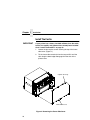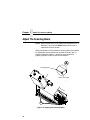
1
Online Data Validator User’s Manual
The Printronix T5000 e series of Thermal Printers
The Printronix T5000 e series of Thermal Printers
Online Data Validator User’s Manual
170895-001H
Software License Agreement
CAREFULLY READ THE FOLLOWING TERMS AND CONDITIONS BEFORE USING THIS PRINTER.
USING THIS PRINTER INDICATES YOUR ACCEPTANCE OF THESE TERMS AND CONDITIONS. IF YOU
DO NOT AGREE TO THESE TERMS AND CONDITIONS, PROMPTLY RETURN THE PRINTER AND ALL
ACCOMPANYING HARDWARE AND WRITTEN MATERIALS TO THE PLACE YOU OBTAINED THEM, AND
YOUR MONEY WILL BE REFUNDED.
Definitions.
“Software” shall mean the digitally encoded, machine-readable data and program. The term “Software
Product” includes the Software resident in the printer and its documentation. The Software Product is licensed
(not sold) to you, and Printronix, Inc. either owns or licenses from other vendors who own, all copyright, trade
secret, patent and other proprietary rights in the Software Product.
License.
1.
2.
3.
Authorized Use. You agree to accept a non-exclusive license to use the Software resident in the printer
solely for your own customary business or personal purposes.
Restrictions.
a.
To protect the proprietary rights of Printronix, Inc., you agree to maintain the Software Product and
other proprietary information concerning the typefaces in strict confidence.
b.
You agree not to duplicate or copy the Software Product.
c.
You shall not sublicense, sell, lease, or otherwise transfer all or any portion of the Software Product
separate from the printer, without the prior written consent of Printronix, Inc.
d.
You may not modify or prepare derivative works of the Software Product.
e.
You may not transmit the Software Product over a network, by telephone, or electronically using any
means; or reverse engineer, decompile or disassemble the Software.
f.
You agree to keep confidential and use your best efforts to prevent and protect the contents of the
Software Product from unauthorized disclosure or use.
Transfer. You may transfer the Software Product with the printer, but only if the recipient agrees to accept
the terms and conditions of this Agreement. Your license is automatically terminated if you transfer the
Software Product and printer.
Limited Software Product Warranty
Printronix, Inc. warrants that for ninety (90) days after delivery, the Software will perform in accordance with
specifications published by Printronix, Inc. Printronix, Inc. does not warrant that the Software is free from all
bugs, errors and omissions.
Remedy
Your exclusive remedy and the sole liability of Printronix, Inc. in connection with the Software is replacement
of defective software with a copy of the same version and revision level.
Disclaimer of Warranties and Limitation of Remedies
1.
THE PARTIES AGREE THAT ALL OTHER WARRANTIES, EXPRESS OR IMPLIED, INCLUDING
WARRANTIES OF FITNESS FOR A PARTICULAR PURPOSE AND MERCHANTABILITY ARE
EXCLUDED.
Printronix, Inc. does not warrant that the functions contained in the Software will meet your requirements
or that the operation of the Software will be uninterrupted or error free.
Printronix, Inc. reserves the right to make changes and/or improvements in the Software without notice at
any time.
2.
IN NO EVENT WILL PRINTRONIX, INC. BE LIABLE FOR LOST PROFITS, LOST DATA, BUSINESS
INTERRUPTIONS, OR ANY OTHER DIRECT, INDIRECT, INCIDENTAL OR CONSEQUENTIAL
DAMAGES ARISING OUT OF THE USE OF OR INABILITY TO USE THIS PRODUCT, EVEN IF
PRINTRONIX, INC. HAS BEEN ADVISED OF THE POSSIBILITY OF SUCH DAMAGES, OR ANY
DAMAGES CAUSED BY THE ABUSE OR MANIPULATION OF THE SOFTWARE. SOME STATES DO
NOT ALLOW THE EXCLUSION OR LIMITATION OF LIABILITY FOR CONSEQUENTIAL OR
INCIDENTAL DAMAGES, SO THE ABOVE LIMITATION MAY NOT APPLY TO YOU.
3.
Printronix, Inc. will not be liable for any loss or damage caused by delay in furnishing a Software Product
or any other performance under this Agreement.
4.
Our entire liability and your exclusive remedies for our liability of any kind (including liability for
negligence except liability for personal injury caused solely by our negligence) for the Software Product
covered by this Agreement and all other performance or nonperformance by us under or related to this
Agreement are limited to the remedies specified by this Agreement.
5.
California law governs this Agreement.
Termination of License Agreement
This License shall continue until terminated. This license may be terminated by agreement between you and
Printronix, Inc. or by Printronix, Inc. if you fail to comply with the terms of this License and such failure is not
corrected within thirty (30) days after notice. When this License is terminated, you shall return to the place you
obtained them, the printer and all copies of the Software and documentation.
U.S. Government Restricted Rights
Use, duplication or disclosure by the Government is subject to restrictions as set forth in the Rights in
Technical Data and Computer Software clause at FAR 242.227-7013, subdivision (b) (3) (ii) or subparagraph
(c) (1) (ii), as appropriate. Further use, duplication or disclosure is subject to restrictions applicable to
restricted rights software as set forth in FAR 52.227-19 (c) (2).
Acknowledgement of Terms and Conditions
YOU ACKNOWLEDGE THAT YOU HAVE READ THIS AGREEMENT, UNDERSTAND IT, AND AGREE TO
BE BOUND BY ITS TERMS AND CONDITIONS. NEITHER PARTY SHALL BE BOUND BY ANY
STATEMENT OR REPRESENTATION NOT CONTAINED IN THIS AGREEMENT. NO CHANGE IN THIS
AGREEMENT IS EFFECTIVE UNLESS WRITTEN AND SIGNED BY PROPERLY AUTHORIZED
REPRESENTATIVES OF EACH PARTY. BY USING THIS PRINTER, YOU AGREE TO ACCEPT THE
TERMS AND CONDITIONS OF THIS AGREEMENT.
Communication Notices
Federal Communications Commission (FCC) Statement: This equipment has been tested and found to
comply with the limits for a Class A digital device, pursuant to Part 15 of the FCC Rules. These limits are
designed to provided reasonable protection against harmful interference when the equipment is operated in a
commercial environment. This equipment generates, uses, and can radiate radio frequency energy and, if not
installed and used in accordance with the instruction manual, may cause harmful interference to radio
communications. Operation of this equipment in a residential area is likely to cause harmful interference, in
which case the user will be required to correct the interference at his own expense.
Properly shielded and grounded cables and connectors must be used in order to meet FCC emission limits.
Printronix is not responsible for any radio or television interference caused by using other than recommended
cables and connectors or by any unauthorized changes or modifications to this equipment. Unauthorized
changes or modifications could void the user’s authority to operate the equipment.
This device complies with Part 15 of the FCC Rules. Operation is subject to the following two conditions: (1)
this device may not cause harmful interference, and (2) this device must accept any interference received,
including interference that may cause undesired operation.
Canadian Department of Communications Compliance Statement: This Class A digital apparatus
complies with Canadian ICES-003.
Avis de conformite aux normes du ministere des Communcations du Canada: Cet appareil numerique
de la classe A est conform á norme NMB-003 du Canada.
European Community (EC) Conformity Statement:
This product is in conformity with the protection requirements of EC Council Directive 89/336/EEC on the
approximation of the laws of the Member States relating to electromagnetic compatibility. Printronix cannot
accept responsibility for any failure to satisfy the protection requirements resulting from a non-recommended
modification of the product, including the fitting of non-Printronix option cards.
German Conformity Statement:
Zulassungsbescheinigung Gesetz über die elektromagnetische Verträglichkeit von Geraten (EMVG) vom 30.
August 1995
Dieses Gerät ist berechtigt in Übereinstimmung mit dem deutschen das EG-Konformitätszelchen - CE - zu
führen.
Der Außteller der Konformitätserklärung ist die Printronix......(1)
Informationen in Hinsicht EMVG Paragraph 3 Abs. (2) 2:
Das Gerät erfüllt die Schutzanforderungen nach EN 55024 und
EN 55022 Klasse A.
EN 55022 Klasse A Geräte bedürfen folgender Hinweise:
Nach dem EMVG: “Geräte dürfen an Orten, für die sie nicht asreichend entstört sind, nur mit besonderer
Genehmigung des Bundesminesters für Post und Telekommunikation oder des Bundesamtes für Post und
Telekommunikation betrieben werden. Die Genehmigung wird erteilt, wenn keine elektromagnetischen
Störungen zu erwarten sind.” (Auszug aus dem EMVG, Paragraph 3, Abs. 4) Dieses Genehmigungsverfahren
ist nach Paragraph 9 EMVG in Verbindung mit der entsprechenden Kostenverordnung (Amtsblatt 14/93)
kostenpflichtig.
Nach der EN 55022: “Dies ist eine Einrichtung der Klasse A. Diese Einrichtung kann im Wohnbereich
Funkstörungen verursachen; in diesem Fall kann vom Betreiber verlangt werden, angemessene Maßnahmen
durchzuführen und dafür aufzkommen.”
Anmerkung: Um die Einhaltung des EMVG sicherzustellen sind die Geräte, wie in den Handbüchern
angegeben, zu installieren und zu betreiben.
This product has been tested and found to comply with the limits for Class A Information Technology
Equipment according to European Standard EN 55022. The limits for Class A equipment were derived for
commercial and industrial environments to provide reasonable protection against interference with licensed
communication equipment.
Warning
This is a Class A product. In a domestic environment
this product may cause radio interference in which
case the user may be required to take adequate
measures.
Printronix makes no representations or warranties of any kind regarding this material, including, but not limited
to, implied warranties of merchantability and fitness for a particular purpose. Printronix shall not be held
responsible for errors contained herein or any omissions from this material or for any damages, whether
direct, indirect, incidental or consequential, in connection with the furnishing, distribution, performance or use
of this material. The information in this manual is subject to change without notice.
This document contains proprietary information protected by copyright. No part of this document may be
reproduced, copied, translated or incorporated in any other material in any form or by any means, whether
manual, graphic, electronic, mechanical or otherwise, without the prior written consent of Printronix.
COPYRIGHT © 2000, 2003 PRINTRONIX, INC. All rights reserved.
Trademark Acknowledgements
Printronix, LinePrinter Plus, IGP, and PGL are registered trademarks of Printronix, Inc.
Code V is a trademark of Quality Micro Systems, Inc.
IPDS is a trademark of International Business Machines Corporation.
Table of Contents
1 Installation Instructions ........................... 11
Overview..............................................................................11
Safety Notices .....................................................................14
Installation ...........................................................................15
Prepare The Printer.......................................................15
Install The Ferrite ..........................................................16
Install The Brackets.......................................................23
Attach The Power/Data Cable To The Validator ...........25
Restore The Printer To Operation .......................................26
Enable The Validator ...........................................................27
Adjust The Scanning Beam .................................................28
Shifting The Scanning Beam.........................................33
Calibration ...........................................................................34
Bar Code Validation Demo Page ..................................36
2 Operation ................................................ 39
Basic Validator Setup ..........................................................39
Validator Menu Structure ..............................................41
Configuring The Validator ....................................................43
Enabling And Disabling The Validator...........................43
Validator Reporting .......................................................43
Validator Statistics.........................................................47
Defining Validator Options ............................................48
Advanced Validator Options..........................................53
Operation.............................................................................57
Print Speed Limits .........................................................57
Demand Printing Modes................................................60
9
Table of Contents
Bar Code Failures................................................................61
Bad Bar Code Error Detection ......................................61
Missing Bar Code Error Detection.................................61
Error Action ...................................................................62
Error Messages.............................................................64
Troubleshooting...................................................................69
Maintenance ........................................................................71
10
1
Installation
Instructions
Overview
The online data validator (validator) is an external bar code
scanning device attached above the paper exit of the printer. When
activated, it scans the printed output looking for bar codes. When it
finds a bar code, it determines what type of bar code it is and
monitors the bar code quality as it passes through the scan area.
After the entire bar code has passed under the scanning beam, the
validator grades the bar code and sends a report to the printer. How
the printer responds is determined by the validator settings,
explained in “Configuring The Validator” on page 43.
Operational Parameters
The design parameters of the validator are as follows:
•
The validator can track the performance of up to four horizontal
bar codes at one time.
•
The validator requires a minimum distance of 1/2 inch or 20
times the minimum element width (x-dimension), whichever is
greater, between bar codes.
•
The validator recognizes the following linear, picket fence bar
codes: Codabar, Code 39, Code 93, Code 128, Interleaved 2 of
5, and UPC/EAN + add-ons.
11
Chapter 1 Overview
•
The validator can also evaluate PDF 417 bar codes. For PDF
417 Limited, the validator works best with security level 5 or
higher, using the current default printer settings for Defects
Percentage, Percent Decode, and Decodeability. For lower
security levels, lower the Defects Percentage to 5% to enable
checking for bar code damage.
•
•
Stacked, 2D, and vertical (ladder) bar codes are not supported.
Bar codes must have a minimum x-dimension of 10 mil
(0.010 inch) to be recognized by the full width of the scanning
beam. The validator can recognize bar x-dimension as narrow
as 6.6 mil (0.0066 inch) for 300 dpi printers, and 10 mil
(0.010 inch) for 203 dpi printers. The validator cannot
recognize x-dimensions smaller than 6.6 mil (0.0066 inch) or
larger than 40 mil (0.040 inch).
Refer to Table 1 for the minimum x-dimension requirements for
each printer size of a 300 dpi printer.
Table 1: Minimum X-Dimension and Beam Width for
a 300 dpi Printer
12
Printer Size
Beam Width
Minimum
X-Dimension
4 inch
4.5 inches
6.6 mil
6 inch
6.5 inches
10 mil
8 inch
8.5 inches
13 mil
Tools And Materials You Will Need
•
•
•
•
Static Wrist Strap
3 mm Allen key
2.5 mm Allen key
T5000 User’s Manual
Parts List
•
•
•
•
•
•
•
•
Validator/Upper Bracket
Lower Bracket
Cable Assembly
Ferrite
Grommet
Wire Saddle
Overlays
Bar Code Calibration Card
13
Chapter 1 Safety Notices
Safety Notices
The validator is a Class 2 laser product. The following notices apply
at all times when the printer is powered on and the validator is
active:
WARNING
Class 2 laser light. Do not stare into the laser beam or a
reflected image of the laser beam.
WARNING
Using controls, making adjustments, or performing
procedures other than those specified herein may result in
hazardous radiation exposure.
Note: This is the laser exit window.
Figure 1. Safety Warnings
14
Prepare The Printer
Installation
Prepare The Printer
1. Set the printer power switch to O (Off).
WARNING
Always unplug the printer power cord from the printer or
power outlet before doing any installation procedure. Failure
to remove power could result in injury to you and damage the
equipment. You will be instructed when to apply power.
2. Unplug the printer power cord from the printer or the AC power
source.
15
Chapter 1 Installation
Install The Ferrite
IMPORTANT
If your printer has a factory installed validator, then the cable,
ferrite, wire saddle, and grommet have already been installed.
Go to “Install The Brackets” on page 23.
1. Loosen the two captive screws securing the top of the frame
side cover. (Figure 2.)
2. Tilt the frame side cover back from the top and lift it until the
tabs along the lower edge disengage from the slots in the
printer frame.
Captive Screw (2)
Frame Side Cover
Figure 2. Removing the Frame Side Cover
16
Install The Ferrite
3. If you have the expansion-CT option:
a. Loosen one screw and remove the other screw that
secures the expansion-CT subassembly to the rear of the
printer frame. (Figure 3.)
b. Carefully lift the expansion-CT subassembly and CT
adapter plate out of the frame cutout.
c.
Unplug the expansion-CT cable from the expansion-CT
port on the controller PCBA and set the expansion-CT
subassembly aside.
Expansion-CT Port
Controller PCBA
Screw (2)
Expansion-CT
Cable
CT Adapter Plate
Expansion-CT
Subassembly
Figure 3. Removing the Expansion-CT Subassembly
17
Chapter 1 Installation
Power/Data Cable
First Wrap
Ferrite
Long Connector
(To Validator)
20.0 ± 0.5
inches
Short Connector
(To Controller Board)
Power/Data Cable
Second Wrap
Figure 4. Wrapping the Power/Data Cable Around the Ferrite
4. Using the end of the power/data cable with the short connector,
insert the cable through the ferrite. (Figure 4.)
5. Wrap the power/data cable around the ferrite twice.
6. Adjust the position of the ferrite so that the length from the
ferrite to the long connector is 20 ± 0.5 inches.
18
Install The Ferrite
Frame Boss
Wire Saddle
Figure 5. Inserting the Wire Saddle Into the Frame Boss
7. Insert the wire saddle into the frame boss. (Figure 5.)
19
Chapter 1 Installation
Wire Saddle
Long Connector
(To Validator)
Ferrite
Hole in the
Frame Wall
Figure 6. Inserting the Power/Data Cable Through the Hole in the Frame Wall
8. Raise the media cover and remove the solid grommet from the
hole in the frame wall.
9. On the electronics side of the printer, insert the long connector
end of the power/data cable through the hole in the frame wall.
(Figure 6.)
10. Insert the power/data cable through the wire saddle.
20
Install The Ferrite
Grommet
Long
Connector
Inserted Grommet
(Media Side)
Power/Data Cable
(approximately
17 inches exposed)
Figure 7. Adding the Grommet to the Power/Data Cable
11. On the media side of the printer, slide the grommet onto the
power/data cable and insert it into the hole in the frame wall.
(Figure 7.)
12. Inspect the power/data cable to ensure approximately
17 inches of cable is exposed from the grommet to connect it to
the validator.
NOTE: You will plug the power/data cable into the validator later.
21
Chapter 1 Installation
J10
Wire Saddle
Ferrite
Upper
DC Motor
Power/Data Cable
Power Supply Cable
Figure 8. Position the Ferrite
13. On the electronics side of the printer, position the ferrite on top
of the upper DC motor. (Figure 8.)
14. Route the power/data cable through the wire saddle, then
under the power supply cable as shown in Figure 8.
15. Plug the power/data cable into the J10 receptacle on the
controller board.
16. Install the expansion-CT subassembly, if you removed it in
step 3, page 17.
22
Install The Brackets
Install The Brackets
Lower
Bracket
M4x10mm
Screw (4)
Figure 9. Installing the Lower Bracket
1. Using the four M4x10mm screws, install the lower bracket as
shown in Figure 9.
23
Chapter 1 Installation
A
Validator
(Rear View)
Hash
Marks
A
4 in. 6 in. 8 in.
Printer
Lower
Bracket
Validator
(Front View)
Upper
Bracket
Adjustment
Screw (2)
Figure 10. Installing the Validator/Upper Bracket Unit onto the Lower Bracket
2. Face the front of the printer while installing the validator/upper
bracket unit.
3. Loosen the two adjustment screws on the bottom of the
validator.
4. Slide the validator/upper bracket unit onto the lower bracket and
align the hash marks accordingly. Refer to Figure 10, Detail A for
location of the validator hash mark for each printer model size.
NOTE: The printer model size is also inscribed on the lower
bracket.
5. When the unit is positioned correctly, tighten the two
adjustment screws on the validator to lock the unit into place.
24
Attach The Power/Data Cable To The Validator
Attach The Power/Data Cable To The Validator
Power/Data Cable
(Long Connector)
Upper Bracket
Screw (3)
Cable
Channel
Bracket Tab
Grommet
Bracket Mounting Screw (4)
Figure 11. Attaching the Power/Data Cable
1. Loosen the three upper bracket screws and route the
power/data cable through the cable channel in the upper
bracket, as shown in Figure 11.
2. Plug the long connector end of the power/data cable into the
validator.
3. Route the power/data cable behind the bracket tab, as shown
in Figure 11.
NOTE: If necessary, loosen the bracket mounting screws enough
to slip the power/data cable behind the bracket tab, then
retighten the bracket mounting screws.
4. Pull the cable to minimize the slack behind the lower bracket.
Push any excess slack through the grommet.
5. Tighten the three upper bracket screws.
25
Chapter 1 Restore The Printer To Operation
Restore The Printer To Operation
1. Lower the media cover.
2. Engage the tabs on the bottom of the frame side cover in the
slots in the printer frame.
3. Rotate the cover into position.
4. Tighten the two captive screws. (Figure 2.)
5. Plug the AC power cord into the printer and the power source.
6. Set the printer power switch to | (On).
26
Attach The Power/Data Cable To The Validator
Enable The Validator
Later version software can automatically detect the validator. When
the printer is powered up with the validator installed, the
VALIDATOR menu appears and Validator Funct. is automatically
set to Enable in the QUICK SETUP and VALIDATOR menus.
NOTE: You may need to load the Factory Config. in the CONFIG
CTRL menu to allow the VALIDATOR menu to appear.
With earlier software that cannot automatically detect the validator,
the default value for Validator Funct. is Disable so that printers
without validators do not stop and wait for the validator at boot up.
These printers with validators installed need to have Validation
Funct. set to Enable. This is a one-time setting if the save
configuration command is issued.
1. Press ... to take the printer offline and place the printer in
Menu mode.
2. If necessary, press ↓ and ↵ at the same time to unlock the
↵ key. (This key combination can be changed by the user. Use
the customer’s key combination if necessary.)
3. If necessary, press
..
.
until “VALIDATOR” displays.
4. Press ↓ until “Validator Funct.” displays.
5. Press + or – until the “Enable” displays.
6. Press ↵ to enable the validator. An asterisk (*) should appear
after “Enable.” Once enabled, the printer will command the
validator to begin scanning and reporting errors, and the
counters will be incremented.
7. Press ↓ and ↵ at the same time to lock the ↵ key, then press
PAUSE to take the printer offline.
8. Press PAUSE again to put the printer online.
27
Chapter 1 Adjust The Scanning Beam
Adjust The Scanning Beam
NOTE: Make sure the printer is on and the scanning beam is on. If
the beam is off, press the RESET button for less than 2
seconds to turn on the beam.
When the validator is first installed, the scanning beam may need to
be aligned with the two notches on the sides of the tear bar, as
shown in Detail A of Figure 12. When the scanning beam is
properly aligned it will line up with the two notches.
A
Scanning Beam
Notch in Tear Bar
t 5lsrlc2
June19, 20 0
A
Figure 12. Aligning the Scanning Beam
28
Attach The Power/Data Cable To The Validator
If your printer is configured for Peel-Off Media Handling mode (use
of optional internal rewinder), you may need to align the beam
further behind the notches (0.20 to 0.30 inches [5.08 mm to
7.62 mm] from the front edge of the tear bar) so that the peeled
label remains on the tear bar and the trailing edge of the last bar
code can still pass completely under the scanning beam. See
Figure 13.
0.30 inches
7.62 mm
Figure 13. Aligning the Scanning Beam – Peel-Off Media Handling Mode
If your printer has a cutter installed, align the beam with the notches
at each side of the opening on the hinged upper lid, as shown in
Detail A of Figure 14.
A
Scanning Beam
A
Notch in Tear Bar/
Cutter
Figure 14. Aligning the Scanning Beam – Cutter Installed
29
Chapter 1 Adjust The Scanning Beam
Top Left Screw
Bottom Left Screw
Bottom Right Screw
Figure 15. Scanning Beam Adjustment Screws
Figure 15 shows the screws used to adjust the parallelism and
position of the scanning beam. The positions of the screws assume
that you are in front of the validator unit and facing the printer. The
following instructions and illustrations show how to adjust the
validator according to how the beam appears.
1. Power the printer on and make sure the scanning beam is on. If
the beam is off, press the RESET button for less than 2
seconds to turn on the scanning beam.
2. Use the Allen key provided to adjust the screws.
NOTE: You may have to loosen all three screws and allow the
rubber spacers to expand (relax) before making any
adjustments.
30
Attach The Power/Data Cable To The Validator
Correct alignment of the
scanning beam. The beam lines
up with the end notches and is
parallel to the long edge of the
tear bar.
Tighten the top left screw to
move the scanning beam
downward. If the screw is
already tight, loosen both bottom
screws to lower the beam.
Tighten both bottom screws to
move the scanning beam
upward. If they are already tight,
loosen the top left screw to move
the beam upward.
Loosen the bottom right screw to
rotate the scanning beam
clockwise. If it is already loose,
tighten the bottom left screw.
Loosen the bottom left screw to
rotate the scanning beam
counterclockwise. If it is already
loose, tighten the bottom right
screw.
31
Chapter 1 Adjust The Scanning Beam
Summary Of Scanning Beam Adjustment
To Move Beam
Down
To Move Beam
Up
To Rotate Beam
Clockwise
To Rotate Beam
Counterclockwise
Tighten top left
screw
Tighten both bottom
screws
Loosen bottom
right screw
Loosen bottom left
screw
or
or
or
or
Loosen both
bottom screws
Loosen top left screw
Tighten bottom
left screw
Tighten bottom
right screw
NOTE: If the printer does not have a tear bar with notches at the
ends, adjust the scanning beam so that the center of the
beam is approximately 0.06 inches (1.52 mm) from the
lower edge as shown in Figure 16.
0.06 inches
(1.52 mm)
Figure 16. Adjusting the Center of the Scanning Beam
32
Shifting The Scanning Beam
Shifting The Scanning Beam
This option enables you to shift the scanning beam horizontally to
the left or right. The left edge of the beam should be approximately
0.13 inches (3.3 mm) from the left edge of the tear bar. After you
set this value, save it as part of the configuration for future use.
The value range is from -99 to 99. The default is 0. Lower values
will move the beam to the left.
NOTE: You must set Admin User to Enable in the PRINTER
CONTROL menu to access the Beam Shift option.
(Refer to the User’s Manual.)
1. Press ... to take the printer offline and place the printer in
Menu mode.
2. If necessary, press ↓ and ↵ at the same time to unlock the
↵ key.
3. If necessary, press
..
.
until “VALIDATOR” displays.
4. Press ↓ until “Validator Funct.” displays.
5. Make sure the “Enable” option is selected.
6. Press ↓ until “Beam Shift” displays.
7. Press + or – to scroll through the values: -99 to 99. The default
is 0. Lower values will move the beam to the left. Press ↵ to
accept the shift value.
Keep selecting the new value until the beam width is at the
desired position. The left edge of beam should be
approximately 0.13 inches (3.3 mm) from the left edge of the
tear bar.
8. Save the configuration for future use.
33
Chapter 1 Calibration
Calibration
WARNING
Class 2 laser light. Do not stare into the laser beam or a
reflected image of the laser beam.
WARNING
Using controls, making adjustments, or performing
procedures other than those specified herein may result in
hazardous radiation exposure.
The validator should be calibrated when it is first installed or when
the printer displays the “Calibration warning” message. A special
calibration bar code card is included with the validator package.
1. Make sure the printer is on and the scanning beam is on. If the
beam is off, press the RESET button for less than 2 seconds to
turn on the beam.
Table 2. RESET Button Settings
Time RESET Button Is Depressed
Result
Less than 2 seconds
Turns on scanning beam
More than 4 but less than 6 seconds
Validator goes into calibration mode
More than 6 seconds
Resets validator to factory calibration and
turns off scanning beam
2. Raise the media cover. Open the pivoting deck by rotating the
deck lock lever fully clockwise. The pivoting deck will swing
upward, exposing the bottom of the printhead assembly.
3. If the printer has the cutter option, put the cutter in the open
(down) position.
4. Remove the calibration bar code card from its protective sleeve
and slide it into the open printhead and under the scanning
beam. (Figure 17.)
5. Make sure the bar code is under the scanning beam and the
CALIBRATION light is on.
6. Press and hold the RESET button on the validator until the
CALIBRATION light begins flashing.
34
Shifting The Scanning Beam
CALIBRATION Light
RESET Button
Deck Lock
Lever
Calibration Bar Code Card
Figure 17. Calibrating the Validator
7. The scanning beam should turn off for a few seconds then back
on, and the CALIBRATION light should turn off. This indicates
a successful calibration.
NOTE: If the scanning beam does not turn back on and/or the
calibration light is still on or flashing, the calibration has
failed. In this case, refer to Table 2 on page 34 to repeat
the calibration procedure or to reset the validator settings
back to factory default.
8. Once you have a successful calibration, remove the calibration
bar code card.
9. Close the pivoting deck and rotate the deck lock lever fully
counterclockwise.
10. Close the media cover.
35
Chapter 1 Calibration
11. Power the printer off, wait a few seconds, then power the
printer on.
If the calibration was successful, the scanning beam is on and
the CALIBRATION light is off.
If the calibration was not successful, the scanning beam
remains on and the CALIBRATION light stays lit without
flashing. Repeat the calibration procedure. If repeated attempts
fail, check the room for excessive ambient light, including direct
sunlight. You may need to move the printer to a darker area of
the room.
NOTE: In some cases the validator can detect and indicate to the
printer that calibration is required. See “Calibration
warning” in Table 4, page 64.
Bar Code Validation Demo Page
The bar code validation demo page allows you to test or
demonstrate the validator operation without a host computer. This
page contains some text and two good bar code symbologies: one
in Code 39, the other in Code 128.
To print and validate the bar code validation demo page:
1. Load the factory default configuration. (Refer to the User’s
Manual.)
2. In the VALIDATOR menu, set Validator Funct. to Enable.
3. In the CALIBRATE CTRL menu, set Gap/Mark Sensing to Gap.
4. Load media.
5. In the CALIBRATE CTRL menu, run Auto Calibrate for proper
gap sensing.
6. The printer must be offline. If the printer is in Menu mode, press
the PAUSE key to take the printer offline.
7. Press the TEST PRINT key to enter the Test Print menu.
Continue to press TEST PRINT until “Barcode Demo” displays.
8. Press the ↵ key to print and validate the demo page. (If the ↵
key is locked, unlock it by pressing ↓ and ↵ at the same time.)
36
Bar Code Validation Demo Page
9. The printer will print one demo page containing two good bar
codes.
NOTE: In the QUICK SETUP or MEDIA CONTROL menu, if Label
Length is set between 0.5 and 1.0 inches, only one good
bar code will print.
If Label Length is less than 0.5 inches and Label Width is
less than 2.0 inches, no demo page will print.
10. To demonstrate a bad bar code reading, block the scanning
beam with an opaque object while the bar code moves under
the beam. When you block the beam, the validator will
generate a reading error and will perform a default error action.
The default setting for the Validator Action in the VALIDATOR
menu is Retry Form.
11. Press PAUSE to take the printer offline.
12. Press ↓ and ↵ at the same time to lock the ↵ key, then press
PAUSE to put the printer back online.
37
Chapter 1 Calibration
38
2
Operation
Basic Validator Setup
Unit Positioning
The validator must be positioned so that the scanning beam covers
the entire area containing the bar codes, including the area
required for quiet zones. The validator can be moved along the
lower bracket and aligned with any of the inscribed hash marks,
depending on the size of the labels printed and the positioning of
the bar codes on those labels. In addition, the beam width can be
moved horizontally to the left or right. See “Summary Of Scanning
Beam Adjustment” on page 32.
If a bar code is completely outside of the scanning area, straddles
an edge, or does not pass completely under the scanning beam,
the validator interprets it as a missing bar code and generates error
conditions.
Validator Front Panel
The front panel of the validator has the following controls and
indicators:
•
POWER: Indicates the validator is at full power.
•
CALIBRATION: Flashes when the validator is in calibration
mode. See page 34 for calibration instructions.
•
READ: Flashes when the validator is reading a bar code.
•
1 and 2: Used for maintenance purposes only.
39
Chapter 2 Basic Validator Setup
•
RESET: This button is used in the calibration procedure and
possible troubleshooting situations. Except in these specific
circumstances, the RESET button should not be used.
Table 3. RESET Button Settings
Time RESET Button Is Depressed
Result
Less than 2 seconds
Turns on scanning beam
More than 4 but less than 6 seconds
Validator goes into calibration mode
More than 6 seconds
Resets validator to factory calibration and
turns off scanning beam
40
CAUTION
Do not lift the printer by the validator unit or by the lower
bracket.
CAUTION
The validator contains sensitive electronic equipment. Do not
jar or drop the unit.
Validator Menu Structure
Validator Menu Structure
VALIDATOR
Validator Report
page 44
Auto Report
page 44
Disable*
Enable
Clear Data
page 45
Good Barcodes
page 47
0
Good Forms
page 47
0
Overstrike Forms
page 47
0
Average BWD
page 47
0%
Last BWD
page 48
0%
Validator Funct.
page 43
Disable*
Enable
Telemetry Path
page 45
Disabled*
Serial Port
Network Port
Telemetry Data
page 46
Short Report*
Full Report
Validation Mode
Number of Codes
page 48
Validator Action
page 62
Auto*
Retry Form*
Continued at the top of next page
1 to 99
Stop
Overstrike
Notes:
* = Factory Default
Italicized items are available only when
you enable Advanced User (in the
PRINTER CONTROL menu).
41
Chapter 2 Basic Validator Setup
VALIDATOR
(cont. from previous page)
Symbol Contrast
page 49
Enable*
Disable
Quiet Zones
page 49
Enable*
Disable
Min. Code Height
page 57
0.25 inches*
0.13 to 1.00 inches
Min. Code Gap
page 59
0.25 inches*
0.15 to 1.00 inches
Skip Labels
page 51
F/W Revision
page 50
Minimum*
Maximum
Version: xxxx (1)
Overstrike Style
page 51
Grid*
I2of5 Checksum
page 52
Disable*
Grey
Checkerboard
Enable
Num Retry
page 52
5*
3
Decodeability
page 53
37%*
30% to 90%
Percent Decode
page 54
60%*
0% to 99%
Defects
page 54
20%*
0% to 100%
Scanner Settings
page 55
Error Type Msg
4
Infinite
Notes:
4xx, 6yy, 8zz* (2)
* = Factory Default
Italicized items are
available only when
you enable Advanced
User (in the
PRINTER CONTROL
menu).
1
Beam Shift
page 56
42
0*
-99 to 99
2
Display item only
Depends on printer
model and custom
files. xx, yy, zz = file
revision numbers.
Enabling And Disabling The Validator
Configuring The Validator
Setting validator options is done through the printer configuration
menu. The validator comes equipped with a default setting for each
configuration option, and it works without having to change any of
these options. However, in some cases it is necessary to adjust
these options, which are described below.
Enabling And Disabling The Validator
1. Press ... to take the printer offline and place the printer in
Menu mode.
2. If necessary, press ↓ and ↵ at the same time to unlock the
↵ key.
3. If necessary, press
..
.
until “VALIDATOR” displays.
4. Press ↓ until “Validator Funct.” displays.
5. Press + or – until “Enable” displays.
6. Press ↵ to enable the validator. An asterisk (*) should appear
after “Enable.” Once enabled, the printer will command the
validator to begin scanning and reporting errors, and the
counters will be incremented.
7. Press ↓ and ↵ at the same time to lock the ↵ key, then press
PAUSE to take the printer offline.
8. Press PAUSE again to put the printer online.
NOTE: To disable the validator once it has been enabled, repeat
steps 1–8 and select the “Disable” option in step 5.
Validator Reporting
After any completed print job, you can request a report from the
printer which describes the validation statistics since the printer
was turned on, or since the last data reset (for information on
resetting data, see page 45).
43
Chapter 2 Configuring The Validator
Requesting A Validator Report
This procedure prints a summarized validator report on the printer
itself.
1. Press ... to take the printer offline and place the printer in
Menu mode.
2. If necessary, press ↓ and ↵ at the same time to unlock the
↵ key.
3. If necessary, press
..
.
until “VALIDATOR” displays.
4. Press ↓ until “Validator Report” displays.
5. Press ↵ to print the report.
6. Press ↓ and ↵ at the same time to lock the ↵ key, then press
PAUSE to take the printer offline.
7. Press PAUSE again to put the printer online.
Setting Auto Report
This function allows you to disable or enable an automatic validator
report printout after a batch job. The factory default is Disable.
You can determine the end of a batch job in two ways:
•
by using an Execute command, or
•
a timeout of more than 10 seconds.
To enable Auto Report:
1. Press ... to take the printer offline and place the printer in
Menu mode.
2. If necessary, press ↓ and ↵ at the same time to unlock the
↵ key.
3. If necessary, press
..
.
until “VALIDATOR” displays.
4. Press ↓ until “Auto Report” displays.
5. Press + or – to scroll through the choices: Enable or Disable.
The default is Disable.
6. When Enable displays, press ↵ to activate Auto Report.
7. Press ↓ and ↵ at the same time to lock the ↵ key, then press
PAUSE to take the printer offline.
8. Press PAUSE again to put the printer online.
44
Validator Reporting
Resetting Validator Data
The validator reports on all bar codes it detects since the last data
reset. For example, you print a large batch of labels with bar codes
and then print a validator report. Then you print another batch of
labels with bar codes and print another report. The report will
contain information on both batch jobs. However, if you reset the
validator data between batch jobs, the second report will only
contain information on the second batch job.
To reset Validator Data:
1. Press ... to take the printer offline and place the printer in
Menu mode.
2. If necessary, press ↓ and ↵ at the same time to unlock the
↵ key.
3. If necessary, press
..
.
until “VALIDATOR” displays.
4. Press ↓ until “Clear Data” displays.
5. Press ↵ to clear validator data.
6. Press ↓ and ↵ at the same time to lock the ↵ key, then press
PAUSE to take the printer offline.
7. Press PAUSE again to put the printer online.
Defining The Data Output Destination (Telemetry
Path)
You may want to send a streaming flow of validation data to an
external device during the print job. Follow the procedure below to
select the data output destination.
1. Press ... to take the printer offline and place the printer in
Menu mode.
2. If necessary, press ↓ and ↵ at the same time to unlock the
↵ key.
3. If necessary, press
..
.
until “VALIDATOR” displays.
4. Press ↓ until “Telemetry Path” displays.
45
Chapter 2 Configuring The Validator
5. Press + or – to cycle through the choices:
•
Disabled. Default setting. The validator does not send any
data to an external device.
•
Serial Port. The printer outputs the bar code analysis and
underlying data from the validator to a device connected to
the serial port, so the validator data can be seen and
analyzed with the optional remote management software.
•
Network Port. The printer outputs the bar code analysis
and underlying data from the validator to a device
connected to the network port so the validator data can be
seen and analyzed with the optional remote management
software.
NOTE: Only one port can be used at a time. If you select Network
Port, the printer front panel will display “DEACTIVATING
HOST SERIAL.”
If you later change the setting to Serial Port, the printer
front panel will display “REACTIVATING HOST SERIAL.”
6. When your selection displays, press ↵ to activate it. All future
reports are output to your selection.
7. Press ↓ and ↵ at the same time to lock the ↵ key, then press
PAUSE to take the printer offline.
8. Press PAUSE again to put the printer online.
Selecting The Type Of Report For the
Data Output Destination (Telemetry Data)
By default, the validator sends the Short Report to the selected
data output destination, but there are two other report options
available: Full Report and Validation Mode.
1. Press ... to take the printer offline and place the printer in
Menu mode.
2. If necessary, press ↓ and ↵ at the same time to unlock the
↵ key.
3. If necessary, press
..
.
until “VALIDATOR” displays.
4. Press ↓ until “Telemetry Data” displays.
46
Validator Statistics
5. Press + or – to cycle through the choices:
•
Short Report. Default setting. Provides the encoded
failure cause or pass indication and the bar width deviation,
shown as a percentage.
•
Full Report. Provides a completed report of all the data
captured by the validator.
•
Validation Mode. Provides the same data as the Short
Report, but adds the actual bar code data read.
6. When your selection displays, press ↵ to activate it.
7. Press ↓ and ↵ at the same time to lock the ↵ key, then press
PAUSE to take the printer offline.
8. Press PAUSE again to put the printer online.
Validator Statistics
The validator displays a number of statistics directly on the printer
LCD, without having to print a report. To view any of the statistics:
1. Press ... to take the printer offline and place the printer in
Menu mode.
2. If necessary, press ↓ and ↵ at the same time to unlock the
↵ key.
3. If necessary, press
..
.
until “VALIDATOR” displays.
4. Press ↓ to scroll through the following statistics on the printer
display:
•
Good Barcodes: The number of bar code reports sent
from the validator since the last Clear Data command.
•
Good Forms: The number of forms printed since the last
Clear Data command.
•
Overstrike Forms: The number of forms containing a bar
code that fell below the minimum acceptable level since the
last Clear Data command.
•
Average BWD: The average of all Bar Width Deviations
reported since the last Clear Data command, shown as a
percentage.
47
Chapter 2 Configuring The Validator
•
Last BWD: The Bar Width Deviation included in the most
recent report received from the validator, shown as a
percentage.
NOTE: A bar code’s Bar Width Deviation is determined by
comparing the bar width the validator expects to the bar
width that is actually printed. For example, if the bar width is
printed exactly as the validator expects, the BWD is 0%.
However, if the bar width as printed is 25% wider or narrower
than the validator expects it to be, it reports a BWD of 25%.
5. Press ↓ and ↵ at the same time to lock the ↵ key, then press
PAUSE to take the printer offline.
6. Press PAUSE again to put the printer online.
Defining Validator Options
A number of validator options which define specific parameters for
certain print jobs can be set from the printer configuration menu.
Setting Number Of Bar Codes On A Form
You can define how many bar codes the validator should expect on
a form. This setting is required when bar codes are produced as a
part of a larger bitmapped image. When set to a specific number,
the printer checks after a form has printed and passed the validator
and determines if it has received an analysis report for each bar
code. If the printer does not have as many reports as it expects, it
can assume a gross bar code failure.
When Auto is selected, the printer only expects as many bar code
analyses as bar codes printed using printer bar code commands
defined by the host software.
1. Press ... to take the printer offline and place the printer in
Menu mode.
2. If necessary, press ↓ and ↵ at the same time to unlock the
↵ key.
3. If necessary, press
..
.
until “VALIDATOR” displays.
4. Press ↓ until “Number of Codes” displays.
5. Press + or – to scroll through the choices: Auto, 1 to 99. The
default is Auto.
48
Defining Validator Options
6. Press ↵ to select the desired value.
7. Press ↓ and ↵ at the same time to lock the ↵ key, then press
PAUSE to take the printer offline.
8. Press PAUSE again to put the printer online.
Setting The Symbol Contrast
Symbol Contrast represents the contrast between the bars and
spaces in the bar code. The bar code must have a certain level of
contrast to be recognized by the validator. When you enable the
Symbol Contrast parameter, the bar code contrast is included as
part of the pass/fail criteria.
1. Press ... to take the printer offline and place the printer in
Menu mode.
2. If necessary, press ↓ and ↵ at the same time to unlock the
↵ key.
3. If necessary, press
..
.
until “VALIDATOR” displays.
4. Press ↓ until “Symbol Contrast” displays.
5. Press + or – to scroll through the choices: Enable or Disable.
The default is Enable.
6. Press ↵ to select the desired value.
7. Press ↓ and ↵ at the same time to lock the ↵ key, then press
PAUSE to take the printer offline.
8. Press PAUSE again to put the printer online.
Checking Quiet Zones
Quiet zones are the white spaces surrounding the bar code. Each
bar code requires a minimum quiet zone distance in order for the
bar code to be scanned properly.
NOTE: The validator requires a minimum distance of 1/2” or 20
times the minimum element width (x-dimension), whichever
is greater, between bar codes.
When the Quiet Zones parameter is enabled, then the bar code
quiet zone is included as part of the pass/fail criteria.
1. Press ... to take the printer offline and place the printer in
Menu mode.
49
Chapter 2 Configuring The Validator
2. If necessary, press ↓ and ↵ at the same time to unlock the
↵ key.
3. If necessary, press
..
.
until “VALIDATOR” displays.
4. Press ↓ until “Quiet Zones” displays.
5. Press + or – to scroll through the choices: Enable or Disable.
The default is Enable.
6. Press ↵ to select the desired value.
7. Press ↓ and ↵ at the same time to lock the ↵ key, then press
PAUSE to take the printer offline.
8. Press PAUSE again to put the printer online.
NOTE: The validator does not recognize x-dimensions greater
than 40 mil with Quiet Zones enabled.
Checking The Firmware Revision Number
For troubleshooting purposes, you may need to reference the
firmware revision number.
1. Press ... to take the printer offline and place the printer in
Menu mode.
2. If necessary, press ↓ and ↵ at the same time to unlock the
↵ key.
3. If necessary, press
..
.
until “VALIDATOR” displays.
4. Press ↓ until “F/W Revision” displays. The firmware version
number displays.
5. Press ↓ and ↵ at the same time to lock the ↵ key, then press
PAUSE to take the printer offline.
6. Press PAUSE again to put the printer online.
50
Defining Validator Options
Setting For Skip Labels
This option is used for skipping blank labels after bad labels have
been marked. It is useful when you want to have extra blank labels
in between bad and good ones. The settings are Minimum (the
default) and Maximum. Minimum allows one blank label, and
Maximum allows two blank labels.
NOTE: Minimum and Maximum blank labels are only applicable for
forms 2 inches (5.08 cm) high or more. For labels less than
2 inches high, the minimum and maximum blank labels
may vary.
1. Press ... to take the printer offline and place the printer in
Menu mode.
2. If necessary, press ↓ and ↵ at the same time to unlock the
↵ key.
3. If necessary, press
..
.
until “VALIDATOR” displays.
4. Press ↓ until “Skip Labels” displays.
5. Press + or – to scroll through the choices: Minimum or
Maximum. The default is Minimum.
6. Press ↵ to select the desired value.
7. Press ↓ and ↵ at the same time to lock the ↵ key, then press
PAUSE to take the printer offline.
8. Press PAUSE again to put the printer online.
Setting Overstrike Style
This option is used for marking bad labels with different overstrike
styles: Grid, Grey, Checkerboard, or Error Type Msg.
1. Press ... to take the printer offline and place the printer in
Menu mode.
2. If necessary, press ↓ and ↵ at the same time to unlock the
↵ key.
3. If necessary, press
..
.
until “VALIDATOR” displays.
4. Press ↓ until “Overstrike Style” displays.
5. Press + or – to scroll through the choices: Grid, Grey,
Checkerboard, or Error Type Msg. The default is Grid.
51
Chapter 2 Configuring The Validator
6. Press ↵ to select the desired value.
7. Press ↓ and ↵ at the same time to lock the ↵ key, then press
PAUSE to take the printer offline.
8. Press PAUSE again to put the printer online.
Setting I2of5 Checksum
This option allows you to include or exclude the checksum option in
the Interleaved 2 of 5 code as part of the grading. For example, if
you enable this option, then any incoming bar code data without
checksum digits will be graded as a failure, and a Checksum
Failure error will display.
1. Press ... to take the printer offline and place the printer in
Menu mode.
2. If necessary, press ↓ and ↵ at the same time to unlock the
↵ key.
3. If necessary, press
..
.
until “VALIDATOR” displays.
4. Press ↓ until “I2of5 Checksum” displays.
5. Press + or – to scroll through the options: Enable or Disable.
The default is Disable.
6. Press ↵ to accept the desired value.
7. Press ↓ and ↵ at the same time to lock the ↵ key, then press
PAUSE to take the printer offline.
8. Press PAUSE again to put the printer online.
Num Retry
This option allows you to set a number of retries for overstrike
before the printer stops.
The options are 3, 4, 5, and Infinite. The factory default is 5.
NOTE: This setting is utilized only if Validator Action is set to Retry
Form. See “Error Action” on page 62.
For the 3, 4, and 5 options, the printer will stop after the specified
number of retry attempts. After you clear the error message, the
printer will print the next label.
52
Advanced Validator Options
For the Infinite option, the printer will stop every 5 retry attempts.
After you clear the error message, the printer will attempt to print
the same label. It will not attempt to print the next label until the
previous (problem) label has printed correctly.
Advanced Validator Options
The following items are considered advanced items and are only
visible if the Advanced menus are selected. Refer to the
configuration section of your User’s Manual for more information.
Decodeability
You can determine how strict the validator grades the wide/narrow
bars and spaces which compose the bar code by setting the
Decodeability parameter to a percentage value from 30% to 90%.
The higher the percentage value chosen, the stricter the validator
grades.
For example, if the Decodeability value is set to 37%, the validator
gives the bar code a failing grade if the decodeability of the bar
code is at or below 37%.
1. Press ... to take the printer offline and place the printer in
Menu mode.
2. If necessary, press ↓ and ↵ at the same time to unlock the
↵ key.
3. If necessary, press
..
.
until “VALIDATOR” displays.
4. Press ↓ until “Decodeability” displays.
5. Press + or – to scroll through the percentage values: 30% to
90%. The default is 37%.
6. Press ↵ to select the desired value.
7. Press ↓ and ↵ at the same time to lock the ↵ key, then press
PAUSE to take the printer offline.
8. Press PAUSE again to put the printer online.
53
Chapter 2 Configuring The Validator
Percent Decode
You can set how strict the validator grades each bar code. For
example, the Percent Decode default value is 60%. This means
that 60% of the scanned bar code must be readable for the
validator to give the bar code a passing grade. You can set the
Percent Decode parameter to a percentage value from 0% to 99%.
The higher the percentage value chosen, the stricter the validator
grades.
1. Press ... to take the printer offline and place the printer in
Menu mode.
2. If necessary, press ↓ and ↵ at the same time to unlock the
↵ key.
3. If necessary, press
..
.
until “VALIDATOR” displays.
4. Press ↓ until “Percent Decode” displays.
5. Press + or – to scroll through the percentage values: 0% to
90%. The default is 60%.
6. Press ↵ to select the desired value.
7. Press ↓ and ↵ at the same time to lock the ↵ key, then press
PAUSE to take the printer offline.
8. Press PAUSE again to put the printer online.
Defects
You can set how strict the validator grades the irregularities such as
voids and spots found within elements and quiet zones for each bar
code. For example, the default value for Defects is 20%. This
means that if the bar code and quiet zone defects exceed 20%, the
validator gives the bar code a failing grade. You can set the Defects
parameter to a percentage value from 0% to 100%. The lower the
percentage value chosen, the stricter the validator grades.
1. Press ... to take the printer offline and place the printer in
Menu mode.
2. If necessary, press ↓ and ↵ at the same time to unlock the
↵ key.
3. If necessary, press
..
.
until “VALIDATOR” displays.
4. Press ↓ until “Defects” displays.
54
Advanced Validator Options
5. Press + or – to scroll through the percentage values: 0% to
100%. The default is 20%.
6. Press ↵ to select the desired value.
7. Press ↓ and ↵ at the same time to lock the ↵ key, then press
PAUSE to take the printer offline.
8. Press PAUSE again to put the printer online.
Scanner Settings
This option has two purposes:
•
Allows the validator to upload an optimized setting for a
particular printer size at power up. This will use the full scanner
beam width and improve the performance and efficiency of the
validator.
•
Allows you to customize a special scanner setting for a specific
application. The file can then be downloaded to the printer by
using normal printer download procedures and must be saved
as part of the power up configuration. For more information,
contact the Printronix Customer Solutions Center at 714-3682686.
To set this option when a special setting has been downloaded:
1. Press ... to take the printer offline and place the printer in
Menu mode.
2. If necessary, press ↓ and ↵ at the same time to unlock the
↵ key.
3. If necessary, press
..
.
until “VALIDATOR” displays.
4. Press ↓ until “Scanner Settings” displays.
5. Press + or – to scroll through the options: Default or a special
file name. Default is the default.
6. Press ↵ to accept the desired value.
7. Save this configuration and set it as the Power-Up
configuration in the CONFIG CTRL menu.
8. Recycle power for the new setting to take effect.
9. The beam may need to be moved horizontally. See “Beam
Shift” on page 56.
55
Chapter 2 Configuring The Validator
Beam Shift
This option enables you to shift the scanning beam horizontally to
the left or right. The left edge of the beam should be approximately
0.13 inches (3.3 mm) from the left edge of the tear bar. After you
set this value, save it as part of the configuration for future use.
The value range is from -99 to 99. The default is 0. Lower values
will move the beam to the left.
NOTE: You must set Admin User to Enable in the PRINTER
CONTROL menu to access the Beam Shift option.
(Refer to the User’s Manual.)
1. Press ... to take the printer offline and place the printer in
Menu mode.
2. If necessary, press ↓ and ↵ at the same time to unlock the
↵ key.
3. If necessary, press
..
.
until “VALIDATOR” displays.
4. Press ↓ until “Validator Funct.” displays.
5. Make sure the “Enable” option is selected.
6. Press ↓ until “Beam Shift” displays.
7. Press + or – to scroll through the values: -99 to 99. The default
is 0. Lower values will move the beam to the left. Press ↵ to
accept the shift value.
Keep selecting the new value until the beam width is at the
desired position. The left edge of beam should be
approximately 0.13 inches (3.3 mm) from the left edge of the
tear bar.
8. Save the configuration for future use.
56
Print Speed Limits
Operation
There are a number of factors which contribute to successful bar
code validation, including printer speed, demand print settings,
calibration, and ambient light. The following sections describe how
to ensure your bar code validator is scanning and reporting
properly.
Print Speed Limits
Two factors in the validation process affect the printer’s speed limit:
bar code height and the validation report type selected.
Bar Code Height (Min. Code Height)
The validator cannot function at the highest speed possible by the
printer. It requires a minimum number of scans per bar code to
make a reliable assessment, so the speed of the printer is limited
by the height of the bar code. If the bar code is very short, printing
needs to be slowed down to allow sufficient scans to occur. If the
print speed exceeds this limit, the message, “Speed Exceeds
Validator Limit” will display. Print speed will be lowered
automatically if required, but will not automatically reset to a higher
speed.
The printer cannot predict how high all the bar codes in a given job
will be, so it cannot automatically limit or adjust the print speed to
insure the code height/speed requirement is being met. When the
bar code is too short for the selected speed, the printer produces a
missing bar code error condition. Therefore, printer speed must be
set manually to compensate for bar code height.
Use this formula to determine printer speed in relation to bar code
height:
Bar Code Height In Inches
0.04
=
Maximum Printer Speed In
Inches Per Second
57
Chapter 2 Operation
For example, a bar code 1 inch in height can scan successfully at a
printer speed of 25 inches per second; a bar code 1/8 inch in height
can scan successfully at no more than 3 inches per second.
By changing the Min. Code Height, the printer and slew speeds will
be changed automatically.
To change the Min. Code Height:
1. Press ... to take the printer offline and place the printer in
Menu mode.
2. If necessary, press ↓ and ↵ at the same time to unlock the
↵ key.
3. If necessary, press
..
.
until “VALIDATOR” displays.
4. Press ↓ until “Min. Code Height” displays.
5. Press + or – to scroll through the choices: 0.13 to 1.00 inches in
0.01 inch increments. The default is 0.25 inches.
6. Press ↵ to select the desired value. The printing and slew
speeds will be changed after ↵ is pressed.
7. Press ↓ and ↵ at the same time to lock the ↵ key, then press
PAUSE to take the printer offline.
8. Press PAUSE again to put the printer online.
To set the printer speed manually:
1. Press ... to take the printer offline and place the printer in
Menu mode.
2. If necessary, press ↓ and ↵ at the same time to unlock the
↵ key.
3. Press
..
.
until “MEDIA CONTROL” displays.
4. Press ↓ until “Print Speed” displays.
5. Press + or – to scroll through the choices.
6. Press ↵ to select the desired value.
7. Press ↓ and ↵ at the same time to lock the ↵ key, then press
PAUSE to take the printer offline.
8. Press PAUSE again to put the printer online.
58
Print Speed Limits
Validation Report Type
Another factor that limits print speed is the type of validation report
selected. The printer automatically examines the selected report
type and sets the defined maximum slew (vertical paper
movement) and print speeds to insure proper operation. If the
current speed selected in the menus is higher than the maximum,
the value is changed to equal the maximum. If the current menu
setting is lower than the newly set maximum, no change in speed
occurs.
Min. Code Gap
Bar code
Min. Code Gap
Distance from the
bottom of a bar code to the
top of the next bar code
Next bar code
Minimum Code Gap represents the distance between the closest
bar codes within a print job. The distance is measured from the
bottom of one bar code to the top of the next bar code. The closest
bar codes can be located on two separate labels or on the same
label.
This distance is important because it affects how fast the Print
Speed can be set. If the bottom-most bar code on one label is very
close to the top-most bar code on the next label, the printer could
have trouble distinguishing which bar code correlates with which
label. To avoid the risk of miscorrelation, the printer automatically
set its Print Speed.
Factory Default = 0.25 inches*
(Range = 0.15 to 1.00 inches in 0.01 inch increments.)
To change the Min. Code Gap:
1. Press ... to take the printer offline and place the printer in
Menu mode.
2. If necessary, press ↓ and ↵ at the same time to unlock the
↵ key.
59
Chapter 2 Operation
3. If necessary, press
..
.
until “VALIDATOR” displays.
4. Press ↓ until “Min. Code Gap” displays.
5. Press + or – to scroll through the choices: 0.15 to 1.00 inches in
0.01 inch increments. The default is 0.25 inches.
6. Press ↵ to select the desired value.
7. Press ↓ and ↵ at the same time to lock the ↵ key, then press
PAUSE to take the printer offline.
8. Press PAUSE again to put the printer online.
NOTE: To avoid the risk of miscorrelation, the printer automatically
sets its Print Speed based on the information that has been
selected to ensure validation results are accurate.
Demand Printing Modes
In order for each bar code to be successfully validated, the entire
bar code must pass completely under the scanning beam, even
when the printer is set up for demand printing mode. In cases
where the bar code is close to the bottom of a label and the printer
is in a demand print mode, the printer automatically pushes the
label past the scanning beam. Once the bar code is validated, the
printer retracts the label back to be cut or torn off.
Because the printer has to push out and then retract labels in
demand modes, the extra movements slow the printing process.
You can avoid this by adjusting the form so that the bar code
appears early enough on the form so that it will pass completely
under the scanning beam during normal printing. This may involve
rotating the form or moving the bar code to a different position on
the form.
60
Bad Bar Code Error Detection
Bar Code Failures
The validator tells the printer to announce a fault condition in two
situations:
•
if the validator detects a bad bar code
•
if the validator detects no bar code where it expects to find one.
How the printer reacts to these faults is determined by the printer’s
configuration settings, as described below.
Bad Bar Code Error Detection
The validator examines every bar code that passes under the
scanning beam and sends an analysis report to the printer. If a bar
code is reported to have failed to meet any of the acceptance
criteria, an error condition is reported. How the printer then reacts is
described in “Error Action” on page 62.
Missing Bar Code Error Detection
A bar code may print so poorly that the validator cannot detect it,
and the printer does not receive an analysis report for the code. To
catch this problem, the printer tracks the position of the last label
printed and knows when it should have completely passed the
scanning beam. It can then compare the number of bar code
analysis reports it expected to the number it received. If the printer
does not receive enough bar code reports, it enters an error
condition. How the printer then reacts is described in “Error Action”
on page 62.
The number of bar codes expected is determined one of two ways:
•
If “Auto” is selected for the “Number of Codes” parameter, and
you are using LinePrinter Plus®, IGP®/PGL®, IGP Code V™, or
IPDS™ graphics software, the printer compares the number of
bar code commands it receives from the software to the
number of analysis reports it receives from the validator.
61
Chapter 2 Bar Code Failures
•
You can set the number of bar codes generated by a
bitmapped image that the printer should expect per form by
selecting a value in the “Number of Codes” parameter.
For more information on choosing a value for the “Number of
Codes” parameter, see “Setting Number Of Bar Codes On A Form”
on page 48.
Error Action
Whether the error stems from a bad or missing bar code, the printer
response is the same. The printer response is determined by the
“Validator Action” setting in the VALIDATOR menu:
1. Press ... to take the printer offline and place the printer in
Menu mode.
2. If necessary, press ↓ and ↵ at the same time to unlock the
↵ key.
3. If necessary, press
..
.
until “VALIDATOR” displays.
4. Press ↓ until “Validator Action” displays.
5. Press + or – to scroll through the choices:
•
Stop
•
Overstrike
•
Retry Form (default)
These options are described in detail below.
6. Press ↵ to select the desired value.
7. Press ↓ and ↵ at the same time to lock the ↵ key, then press
PAUSE to take the printer offline.
8. Press PAUSE again to put the printer online.
Stop
If the system detects a bar code failure, the print job stops, the
printer status indicator lamp flashes, the alarm sounds, and the
appropriate error message displays.
62
Error Action
The printer remains in a fault condition until you press the PAUSE
key. This clears the error message and takes the printer offline.
You must correct any condition that may have caused the fault.
When ready, the printer can be put back online and it will resume
printing where it left off.
Overstrike
Use Overstrike mode when you want bad labels to be marked, but
not reprinted (i.e., when using pre-numbered labels).
If the system detects a bar code failure, the print job stops, the
printer status indicator lamp flashes, the alarm sounds, and the
appropriate error message displays.
Without pausing, the printer then automatically reverses to the top
of the form containing the failing bar code. It then prints an
obliterating pattern over the form and any other forms partially
printed prior to the physical stop. By default, the obliterating pattern
is a grid of fine lines which clearly marks the label as bad but allows
you to read what was originally printed.
In the VALIDATOR menu, the Overstrike Style options are: Grid,
Grey, Checkerboard, or Error Type Msg.
NOTE: To see the error message printed on the bad label as the
Overstrike Style, select the Error Type Msg option.
After the overstrike printing, the printer clears the error message
and stops the alarm, then resumes normal printing at the point the
job was stopped. The overprinted labels are lost and a separate
print command is required to resend them from the host, if needed.
Retry Form
This mode is similar to the Overstrike mode, however, instead of
resuming printing where the printer had left off, the printer will
attempt to reprint the bad form.
NOTE: The number of times the printer will attempt to reprint the
bad form is determined by the Num Retry setting. See
“Num Retry” on page 52.
63
Chapter 2 Bar Code Failures
The printer will stop, indicate an error, and overstrike as described
above. Then it will skip a number of blank labels, depending on the
setting for Skip Labels (see “Setting For Skip Labels” on page 51).
It will then slew to the next top of a blank form and reprint the entire
form that contained the bad bar code and any other forms that were
perhaps interrupted by the error.
NOTE: Because of physical differences between the location of the
print head and the scanning beam, it is likely that a second
form will be started before the first form has finished being
assessed. Therefore, the reprint operation will need to
reprint more than just the form with the error.
If the printer has to reprint the same form five times in a row, the
print job stops completely and behaves the same as in Stop mode.
Error Messages
The validator can detect a number of errors. When one of these
errors occurs, the validator alerts the printer to perform the currently
selected error action (see “Error Action” on page 62) and show the
appropriate error message on the printer display. Validator error
messages are explained in Table 4.
Table 4. Message List
Message
Bar Code Improper
Data Format
64
Explanation
Data validation error: the bar
code is not properly encoded.
For example, a check sum is
incorrect, a required number
of characters is not met, or
the required terminator
characters are not included.
This problem is almost
always caused by incorrect
form or host application
design.
Solution
Fix the application so it
sends data in the correct
bar code format.
Error Messages
Table 4. Message List
Message
Bar code quiet
zone too small
Explanation
Data validation error: the
blank zone(s) left or right of
the bar code is not big
enough to meet the minimum
requirement.
Solution
1. Fix the application.
2. Disable Quiet Zone in
the VALIDATOR menu.
Typically, this occurs in forms
where bar codes are placed
too close to other elements,
the bar code is too close to an
edge of the media, or the
media’s position is shifting.
The minimum quiet zone on
each end of the bar code
should be ten times the
minimum element width or 1/
4 inch, whichever is greater.
In addition, between bar
codes, the validator requires
a minimum distance of 20
times the minimum element
width or 1/2 inch, whichever is
greater.
Calibration
warning
The validator has detected
that it needs calibration. This
message is a reminder and
does not halt printing.
Press PAUSE to clear the
message. Calibrate the
validator. See “Calibration”
on page 34.
Checksum Failure
The bar code data fails the
checksum check or is missing
the checksum digit.
Verify that the checksum
digit exists in the bar code
and that it is the correct
value.
65
Chapter 2 Bar Code Failures
Table 4. Message List
Message
Explanation
Solution
Contrast too low
Check media
Data validation error: the
contrast between bars and
spaces is not sufficient. This
can be caused by too little
heat in the thermal transfer or
by use of colored media or
ribbons.
Increase Print Intensity or
reduce Print Speed in the
QUICK SETUP menu or via
host software, change
media, or disable Symbol
Contrast in the VALIDATOR
menu.
Poor scanning
Check heat&head
Data validation failure:
decodeability. The difference
between wide and narrow
elements is too close for the
validator to reliably discern.
This usually indicates an
improperly set heat/speed/
pressure combination or the
loss of a printhead element.
1. Adjust Print Intensity
and Print Speed in the
QUICK SETUP menu or
via host software.
Data validation failure:
percent decode. The validator
detected gross
inconsistencies within the
height of the bar code. These
types of failures are likely
attributed to large blemishes
within the bar code, caused
by ribbon wrinkle or debris on
media.
1. Check for a wrinkled
ribbon or debris on
media. Roll wrinkled
area onto take-up
spindle.
Poor scanning
Check media
66
2. Adjust the printhead
pressure. (Refer to the
Quick Setup Guide or
User’s Manual.)
2. Adjust the printhead
pressure blocks. (Refer
to the Quick Setup
Guide or User’s
Manual.)
Error Messages
Table 4. Message List
Message
Poor scanning
Inspect head
Speed Exceeds
Validator Limit
Explanation
Solution
Data validation failure:
hardware defect. The
validator detected
unexpected dark spots in
spaces or light spots in bars.
This usually indicates a poor
ribbon/media combination, a
dirty printhead, or a burned
pixel.
1. Check that paper and
ribbon are clean,
unwrinkled, and
installed correctly.
Print Speed is set above 6
IPS as the Power-Up
configuration with the
validator option installed. An
attempt was made to set Print
Speed above 6 IPS in the
QUICK SETUP menu or via
host software.
Change Print Speed in the
QUICK SETUP menu or via
host software to 6 IPS or
less when using the
validator option and save
the new value as the
Power-Up configuration in
the CONFIG CTRL menu.
2. Clean the printhead.
3. If message reappears,
replace the printhead.
67
Chapter 2 Bar Code Failures
Table 4. Message List
Message
Unscannable code
check media
Explanation
Data validation error: missing
bar code. An expected bar
code is missing or was
printed so poorly that the
validator cannot detect it.
Solution
1. Check that paper and
ribbon are clean,
unwrinkled, and
installed correctly.
2. Run a print job and
check that the validator
beam is not obstructed;
remove obstructions as
necessary.
3. Run a print job and
check that the READ
LED flashes as bar
codes exit the printer. If
the READ LED does not
flash, cycle power and
run the job again. If the
READ LED does not
flash, inspect the cables
and the cable
connections. If the
cables are undamaged
and the connections are
good, replace the
validator.
4. Press PAUSE to clear
the message.
5. In the VALIDATOR
menu, press ↓ until
“Clear Data” displays,
then press ↵.
Validator not
communicating
68
The Validator Funct. = Enable
in the VALIDATOR menu, but
when the printer was first
powered up it could not
communicate with it.
Check that the validator
signal cable is securely
connected to the validator
unit.
Error Messages
Troubleshooting
If you are having problems with the validator, consult Table 5 for a
list of symptoms and possible solutions.
Table 5. Troubleshooting the Validator
Symptom
The scanning beam does not
come on.
Solution
1. Make sure the power/data cable is plugged
into the validator and the controller board on
the printer. See “Installation” on page 15.
2. Make sure the validator has not been
disabled in the VALIDATOR menu. See
“Enabling And Disabling The Validator” on
page 43.
3. Print a bar code validation demo page
(page 36).
4. Call your service representative if the
problem persists.
The scanning beam does not
cover the entire width of the
labels being printed.
1. Adjust the validator along the length of the
lower bracket so that the scanning beam
covers the complete width of labels printed.
See “Installation” on page 15.
2. Use “Beam Shift” to move the beam
horizontally to cover the entire width of the
labels. See “Shifting The Scanning Beam”
on page 33.
Printing 3 mil or 5 mil x-dimension
width bar codes constantly
causes error messages.
The validator does not recognize x-dimensions
as small as 3 mil or 5 mil. If you have to print bar
codes this size, disable the validator to prevent
error reports. See “Enabling And Disabling The
Validator” on page 43.
69
Chapter 2 Troubleshooting
Table 5. Troubleshooting the Validator
Symptom
Solution
The printed labels look clean, but
the validator is still reporting an
error message.
The validator glass may be dirty, distorting the
report results. Power down the printer and clean
the glass using a household glass cleaner and a
dry, lint-free cloth.
The printed bar codes are
causing error conditions.
There are a number of factors which could be
causing validation errors:
70
•
The scanning beam is not properly aligned
with the two notches on the tear bar of the
printer. See “Adjust The Scanning Beam” on
page 28.
•
Make sure the entire bar code passes
completely under the scanning beam.
•
The validator and printer are not properly
communicating. Test the validator operation
without using a host. See “Bar Code
Validation Demo Page” on page 36.
•
Bar code width. The validator can recognize
x-dimensions as narrow as 6.6 mil for
300 dpi printers, and 10 mil for 203 dpi
printers. The validator cannot recognize
x-dimensions smaller than 6.6 mil or larger
than 40 mil.
•
Bar code size. A minimum height of 1/8 inch
is required for validation.
•
Bar code type. The validator only
recognizes the following linear, picket fence
bar codes: Codabar, Code 39, Code 93,
Code 128, Interleaved 2 of 5, and UPC/EAN
+ add-ons. Stacked, 2D, and vertical
(ladder) bar codes are not supported.
Error Messages
Table 5. Troubleshooting the Validator
Symptom
Solution
•
Bar code spacing.The validator requires a
minimum distance of 1/2 inch or 20 times
the minimum element width, whichever is
greater, between bar codes.
•
Printer speed. See “Print Speed Limits” on
page 57.
•
Be sure the bar code is not printing on the
extreme edges of the label.
•
Check the number of bar codes being
validated concurrently. The validator can
track the performance of up to four bar
codes at one time.
Maintenance
WARNING
Class 2 laser light. Do not stare into the laser beam or a
reflected image of the laser beam.
WARNING
Using controls, making adjustments, or performing
procedures other than those specified herein may result in
hazardous radiation exposure.
The validator is a self-contained unit that requires only periodic
cleaning. Every so often, power down the printer and use a
household glass cleaner and a dry, lint-free cloth to clean the glass.
If the problem with the printer is not fixed by one of these
troubleshooting methods, call your authorized service
representative or the Printronix Customer Solutions Center.
71
Chapter 2 Maintenance
72
Index
A
D
Auto detect bar codes, 48, 61
Decodeability, 53
Auto Report, 44
Defects, 54
Average BWD command, 47
Demand printing, 60
B
Demo Page, 36
Disabling validator, 43
Bad bar codes, 61
E
Bar Code Demo Page, 36
Bar code failure, 61
Enabling validator, 43
Bar Code Improper / Data Format, 64
Error action, 62
Bar code quiet / zone too small, 65
Overstrike Mode, 63
Bar codes supported, 11
Retry Form, 63
Bar width deviation, 47, 53
Stop Mode, 62
Beam Shift, 56
Error messages
BWD, 48
Bar Code Improper / Data Format, 64
C
Bar code quiet / zone too small, 65
Calibration / warning, 65
Calibration / warning, 65
Checksum Failure, 65
Calibration, setting, 34
Contrast too low / Check media, 66
Checksum Failure, 65
Poor scanning / Check heat&head, 66
Clear Data command, 45
Poor scanning / Check media, 66
Clear validator data, 45
Poor scanning / Inspect head, 67
Configuring, 43
Speed Exceeds / Validator Limit, 67
Contrast too low / Check media, 66
Unscannable code / check media, 68
Validator not / communicating, 68
External device reporting, 45
73
Index
F
O
Firmware revision, 50
Online Data Validator
Form correlation, 59
See Validator
Overstrike Forms command, 47
Overstrike Mode, 63
Overstrike Style, 51
Form parameters, 48
Full Report, 46
F/W Revision command, 50
G
P
Good Barcodes command, 47
Panel, 39
Good Forms command, 47
Parameters, 11
Grading, 54
Percent Decode, 54
I
Poor scanning / Check heat&head, 66
Poor scanning / Check media, 66
Installing the validator, 15
L
Last BWD command, 48
Poor scanning / Inspect head, 67
Print speed limits, 57
Printing reports, 44
Q
M
Quiet zone, 49
Maintenance, 71
R
Missing bar code, 61
N
Num Retry, 52
Number of Codes command, 48
Number of codes on a form, 48
Reports, 43
external device, 45
resetting data, 45
selecting type, 46
Requesting reports, 44
Resetting data, 45
Retry Form, 63
74
Index
S
V
Scanner Settings, 55
Validation Mode, 46
Setting Auto Report, 44
Validator
Setting calibration, 34
Bar Code Demo Page, 36
Short Report, 46
bar code failure, 61
Skip Labels command, 51
calibration, 34
Speed Exceeds / Validator Limit, 67
configuration, 43
Speed limits, 57
disabling, 43
Statistics
enabling, 43
Average BWD, 47
error action, 62
Good Barcodes, 47
installation, 15
Good Forms, 47
maintenance, 71
Last BWD, 48
options, 48, 53
Overstrike Forms, 47
panel, 39
Stop Mode, 62
parameters, 11
Symbol Contrast command, 49
reporting, 43
T
statistics, 47
Validator Funct. command, 27, 43
Telemetry Path, 45
Validator not / communicating, 68
Troubleshooting, 69
Validator Report command, 44
U
Unscannable code / check media, 68
75
Index
76
Printronix, Inc.
14600 Myford Road
Irvine, CA 92606-1005
Phone: (714) 368-2300
Fax: (714) 368-2600
Customer Solutions Center: (714) 368-2686
Printronix
Nederland BV
P.O. Box 163, Nieuweweg 283
NL-6600 Ad Wijchen
The Netherlands
Phone: (31) 24 6489489
Fax: (31) 24 6489499
Printronix Schweiz GmbH
42 Changi South Street 1
Changi South Industrial Estate
Singapore 486763
Phone: (65) 6542-0110
Fax: (65) 6543-0220
Visit our web site at:
www.printronix.com
*170895-001*
170895-001
Revision H