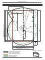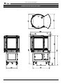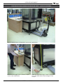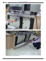
1
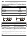
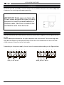
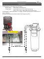
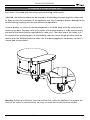
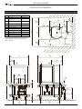
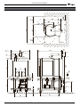
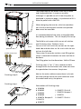
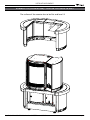
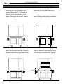
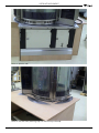
INSTALLATION
MANUAL
DELI MULTISSERIE
Stand alone
(Operator side)
Built in
(Customer side)
(Operator panel on left side)
- NOTICE This manual is prepared for the use of trained Service Technicians and should not be used by those not properly qualified. If
you have attended a trianing for this product, you may be qualified to perform all the procedures in this manual.
This manual is not intended to be all encompassing. If you have
not attended a training for this product, you should read, in its
entirety, the repair procedure you wish to perform to determine
if you have the necessary tools, instruments and skills required
to perform the procedure. Procedures for which you do not have
the necessary tools, instruments and skills should be performed
by a trained technician.
Reproduction or other use of this Manual, without the express
written consent of Fri-Jado, is prohibited.
WWW.FRIJADO.COM
Installation Manual Deli Multisserie form 9123551 rev. 02/2010
Page 2
Installation Manual Deli Multisserie form 9123551 rev. 02/2010
TABLE OF CONTENTS
Index
Index................................................................................................................................ 3
General technical data..................................................................................................... 4
Technical data..............................................................................................................................4
Water requirements......................................................................................................................4
Installation procedures..................................................................................................... 5
Unpacking the unit.......................................................................................................................5
Removal of pallet.........................................................................................................................5
Location......................................................................................................................................6
Electrical supply...........................................................................................................................6
Water supply................................................................................................................................7
Before first use.............................................................................................................................8
Ventilation of the multisserie.........................................................................................................8
Instructions for operators..............................................................................................................8
Tethering a stand alone unit..........................................................................................................9
Installation drawings...................................................................................................... 10
Stand alone unit . ......................................................................................................................10
Example of stand alone unit with exhaust pipe.............................................................................11
Description build - in unit ..........................................................................................................12
Example of (showroom) counter for build-in unit .......................................................................13
Method of installation build-in unit .............................................................................................14
“Footprint” sizes build-in unit ....................................................................................................15
Dimensions build-in unit . ..........................................................................................................16
Installation example build-in unit (photo show)..........................................................................17
Installation Manual Deli Multisserie form 9123551 rev. 02/2010
Page 3
GENERAL TECHNICAL DATA
General technical data
This manual covers the Fri-Jado Deli Multisserie ovens. All of the information, illustrations
and specifications contained in this manual are based on the latest product information available at the time of printing.
Technical data
Type
Deli Multisserie
Power
20.6 kW
Fuses needed with power connection
400V, 3N~50...60 Hz
3x32 A
Fuses needed with power connection
230V, 3~50...60 Hz
3x63A
Power connection
see figure below
Net weight
445 kg
Gross weight
548 kg
Height incl. underframe
1900 mm
Width
980 mm
Depth
1300 mm
Warning: all electrical connections must comply with local codes.
1
2
3
4 1
5 2 6 3 7 4
L1
L1 L3
L2
230V, 3~50...60 Hz
L2
5 1
L3L1
6 2
7 3
L2
L3
4 1
5 2
6 3
7 4
5
6
7
N L1 L2 L3 N
400V, 3N~50...60 Hz
Water requirements
Water hardness
pH
Chlorides
Water pressure at inlet point
less than 7° KH
7.0 - 8.0
less than 30 ppm
minimum 2 bar at 60 liter per minute
Use sediment pre-filter or a strainer for the reduction of silica and other non-dissolved sediments plus an active carbon pre-filter for the reduction of chlorine. In case of water hardness
of 4 grains per gallon or more, use a decalcifying filter for reducing calcium. Contact your
local water supplier for details regarding water quality.
Water pressure available to the Multisserie (after passing the filters) must be at a minimum
of 2 bar at 15 liter per minute flow.
Warning: all plumbing connections must comply with local sanitary, safety and plumbing
codes.
Page 4
Installation Manual Deli Multisserie form 9123551 rev. 02/2010
INSTALLATION PROCEDURES
Installation procedures
•
•
•
•
•
•
•
•
Unpacking of the unit.
Remove the pallet under the unit with the help of a fork lift.
Put the unit on his location.
Check if there is enough free space around the unit (see installation drawing).
Check the electrical supply.
Tethering the oven
Load a program in the memory and make a test run on 250°C.
Give instructions to the operator.
Unpacking the unit
Immediately after unpacking the oven, check for possible shipping damage. If the oven is
found to be damaged, save the packaging material and contact the carrier within 15 days of
delivery.
Removal of pallet
The standard way to remove the multisserie from
a pallet is with a fork lift. See picture. Lift the unit
from pallet and put the unit in its place.
Another possibility is to roll it from the pallet with
help of the wedges, supplied with the oven. See
“unpacking” drawing.
Warning: Do this with at least two persons. The
oven is top heavy. Remove obstacles from the
floor first.
Door
support
5
Only for transport,
remove after transport.
Installation Manual Deli Multisserie form 9123551 rev. 02/2010
Page 5
INSTALLATION PROCEDURES
Location
The oven must be installed on a level surface. The installation location must allow adequate
clearances for servicing and proper operation.
IMPORTANT: Make sure you leave sufficient space around the oven to easily
remove or insert the meat baskets or
chicken racks. The floor on which the
multisserie rests must be level.
Electrical supply
Prior to installation, test the electrical service to assure that it agrees with the specifications
on the
machine data plate located on the right side panel near the controls. The connecting cable
must be connected to a manual disconnect switch that is installed near the unit in a clear
visible manner. Also refer to the local codes.
Depending on the power supply, the unit must be connected according to the figure below.
1
2
3
4 1
5 2 6 3 7 4
L1
L1 L3
L2
230V, 3~50...60 Hz
Page 6
L2
5 1
L3L1
6 2
L2
7 3
L3
4 1
5 2
6 3
7 4
5
6
7
N L1 L2 L3 N
400V, 3N~50...60 Hz
Installation Manual Deli Multisserie form 9123551 rev. 02/2010
INSTALLATION PROCEDURES
Water supply
The Multisserie has two water inlet connections:
-
Normal water: used during the cleaning cycle
-
Filtered water: used during the final rinse of the cleaning cycle
used to make steam if required during the cooking cycle
See paragraph “water requirements” in chapter “General Technical Data” to determine if a
filter is necessary
Before connecting the water hoses remove the two gray caps first.
filtered water
Installation Manual Deli Multisserie form 9123551 rev. 02/2010
Page 7
INSTALLATION PROCEDURES
Before first use
The oven must be burned in to release any odours that might result from heating the new
oven surfaces. Operate the oven at maximum temperature setting of 250°C for 30 minutes.
Smoke with an unplaesant odour will normally be given off during this burn-in period.
Ventilation of the multisserie
- Ventilation is needed only if required by local codes
- The minimum capacity of the extraction hood has to be 1700 m3/h
- The extraction hood has to extend minimum by 200 mm on all sides of the oven
- The extraction hood has to have a free hight, above the rotisserie, of a minimum of 200 mm
- The rotisserie has to be accessible for service purposes
Instructions for operators
After installation of the oven, the operator of the unit has to be instructed.
The instruction has to cover the following subjects:
•
•
•
•
•
•
•
Page 8
Programming and options.
Working of the unit.
Free space of unit for cooling of drive motor and blowers.
Run through the user manual.
Refer to the storyboard, training guide and laminated sheet with pre-programmed programs.
Periodical maintenance.
How to react for information or service calls.
Installation Manual Deli Multisserie form 9123551 rev. 02/2010
INSTALLATION PROCEDURES
Tethering a stand alone unit
Each oven is furnished with two swivel and two locking swivel castors.
If desired, the Multisserie base can be secured to the building structure (typically either wall
or floor) to limit the movement of the appliance and, thus, helping to prevent damage to the
conduit during cleaning, maintenance and service operations.
A tether bracket, as shown on the drawing below, is installed along with the caster to one
corner of the base. The open hole in the center of the tether bracket is to be used to secure
one end of the tether (locally supplied chain, cable, etc.). The other end of the tether is to
be secured to an anchoring point in the building structure. Note: Length of tether must be
shorter than the flexible conduit to make sure that during appliance movement, no stress is
transmitted to the conduit.
Warning: Following installation, check to confirm that, when the appliance is moved to the
limits of the tether in each direction, no stress is transmitted to the electrical conduit.
Installation Manual Deli Multisserie form 9123551 rev. 02/2010
Page 9
INSTALLATION DRAWINGS
Installation drawings
Stand alone unit
Desciption of to the labels on the drawings
Label
Description
1
Power cable
length 2,6 m.*
2
Water supply “G” 3/4”
(see page 11)
hose length 1,2
m. *
3
Water drain Multisserie
35 mm stainless
steel
4
Exhaust pipe Multisserie
80 mm
5
Exhaust
5a
Condens drain pipe
6
Holes for forklift
7
Space between unit and wall
8
Location for wall socket
9
Location for tap
10
Location for drain pipe
7
7
7
7
9
2
4
9
2
3
8
4
10
3
8
10
* Length measured from the point at the rear
of the Multisserie where the hose and the
cable come out.
1
1
7
7
4
4
4
4
8
8
2
1
6
3
3
3
1
9
110
10
40
40
10
10
Page 10
110
3
3
10
9
3
10
2
6
10
Installation Manual Deli Multisserie form 9123551 rev. 02/2010
INSTALLATION DRAWINGS
Example of stand alone unit with exhaust pipe
7
7
9
2
4
3
8
10
1
7
5
100
100
100
5
70
40
4
40
4
4
5a
8
2
6
9
1 3
3
3
10
110
10
Installation Manual Deli Multisserie form 9123551 rev. 02/2010
40
10
Page 11
INSTALLATION DRAWINGS
Double
water
in
let
Description build - in unit
The underframe of the Build-in unit has 5 castors
and 4 adjustable feet. It comes on a pallet.
Although it is possible to roll it from the pallet as
explained in a previous page, it is preferred to lift it
from the pallet with a fork lift!
When designing the counter, take into consideration that the service panel and the two operator
doors must be accessible.
It is recommended to have acces to the adjustable
feet during installation. This wil simplify the set-up.
Service
panel
Operator doors
Double water inlet
Mains Cable entrance
c
la
te
e
ac
e
rp
679
10
44
b
d
sp
f
Finishing strip “c” (or “j”) has a knock-out hole
through which the two water inlet tubes can enter
the space below the counter. See picture.
g
a
Next to the mains cable entrance there is a knockout hole through which the mains cable can enter
the underframe cavity. See picture.
Finishing strips R
h
Finishing strips L
d
i
f
a
g
k
Page 12
The Build-in unit comes with two sets of stainless
steel finishing strips. Thickness 1mm.
One set is for a unit with the controls on the right
hand side and the other set for a unit with the controls on the left side.
These strips fit around a stainless steel filling plate
which is mounted in between the oven and the underframe.
The filling plate has the dimensions 1044 x 679 mm
j
b
Partnumbers of finishing strips
a 9194564
h 9194575 Plinth R
b 9194562
i 9194578 Bumper L
c 9194568
j 9194570
d 9194566
k 9194577 Plinth L
e 9194574 Bumper R
f 9194573
g 9194572
Installation Manual Deli Multisserie form 9123551 rev. 02/2010
INSTALLATION DRAWINGS
Example of (showroom) counter for build-in unit
The surface of the counter has to be flat and level !!!
1065
7
69
Installation Manual Deli Multisserie form 9123551 rev. 02/2010
Page 13
INSTALLATION DRAWINGS
Method of installation build-in unit
Wheel the unit into the gap in the
counter. When size “Z” is lower than
780 mm, this is possible on its own
wheels. Otherwise the help of a pallet
truck is necessary.
Screw out the feet and remove the
wheels.
Note: A pallet truck makes installation
more convenient in all cases.
Z
Adjust the feet untill the top of the underframe equals the top of the counter.
Slide the stainless steel finishing strips
into the slots and finish with sealant.
Finishing strips
Spacer plate
1 mm
Page 14
Installation Manual Deli Multisserie form 9123551 rev. 02/2010
INSTALLATION DRAWINGS
“Footprint” sizes build-in unit
497,6
384,9
776
504
1097
(lenght filling plate)
483
445
240
1044 ± 0,05
(outside underframe)
1060
1070 Maximum !!
(gap in counter)
619,6
794
Ø 60
A
128
679 ± 0,05
695
(width filling plate)
(outside underframe)
700 Maximum !!
Outlines from finishing strips
Outside from underframe.
Cut out from gap in counter
Footprint from oven
Outside from oven
Installation Manual Deli Multisserie form 9123551 rev. 02/2010
(gap in counter)
sideview A (bumper)
136
97
Page 15
INSTALLATION DRAWINGS
960
964
Dimensions build-in unit
1256
74
567
695
Page 16
150
863
1955
1876
1092
122
1060
Installation Manual Deli Multisserie form 9123551 rev. 02/2010
INSTALLATION DRAWINGS
Installation example build-in unit (photo show)
Wheel the Multisserie to the desired location with a pallet truck.
Determine the height of the counter for each
corner of the underframe.
Adjust the adjustable legs in order to align the
top of the underframe with the height of the
counter.
Installation Manual Deli Multisserie form 9123551 rev. 02/2010
Page 17
INSTALLATION DRAWINGS
Connect the bumper for the unit.
Connect the plinth for the under frame.
Page 18
Installation Manual Deli Multisserie form 9123551 rev. 02/2010
INSTALLATION DRAWINGS
View on operator side.
View on customer side. (finishing strips still need to be positioned).
Installation Manual Deli Multisserie form 9123551 rev. 02/2010
Page 19
Fri-Jado B.V. • P.O. Box 560 • 4870 AN • Etten-Leur • The Netherlands • tel +31 76 50 85 400 • fax +31 76 50 85 444 • [email protected] • www.frijado.com
Page 20
Installation Manual Deli Multisserie form 9123551 rev. 02/2010