1
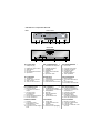
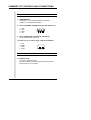
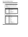
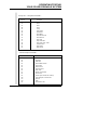
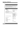
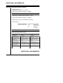
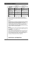
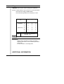
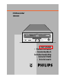
CD-Recorder
CDD2600
CDD 2600
Recordable
DISC IN
PHONES
WRITING
OPEN
CLOSE
ERROR
' User's manual
f Manuel d'utilisation
d Benutzerhandbuch
Gebruikershandleiding
i Guida dell'Utente
e Guia del usuario
CDD 2600 CD - Compact Disc Recorder
FRONT VIEW
FIG.1
Recordable
1
3
2
4
5
6
REAR VIEW
7
8
9
10
FIG.1 FRONT VIEW
'
1. Headphone plug
2. Headphone volume control
3. Write indicator
4. Disc Tray
5. Disc In/Read/Error indicator
6. Open/Close
ABB.1 VORDERANSICHT d
1. Anschlußbuchse Kopfhörer
2. Lautstärke Kopfhörer
3. Schreibanzeige
4. Schublade
5. Diskette ein/Lesen/Fehler
anzeige
6. Open/Close Taste
FIG.1 PARTE ANTERIORE i
1. Presa cuffie
2. Controllo volume cuffie
3. Indicatore di scrittura
4. Cassetto del disco
5. Indicatore disco
inserito/Leggi/Errore
6. Tasto Apri/Chiudi
FIG.1 REAR VIEW
7. Jumperblock
8. Host DC power connector
9. SCSI connector
10. Audio Line Out connector
RÜCKANSICHT
7. Jumperblock
8. Host Gleichstromnetzanschluß
9. SCSI Connector
10. Tonanschluß Aus-Connector
PARTE POSTERIORE
7. Blocco Jumpers
8. Connettore alimentazione
DC
9. Connettore SCSI
10. Connettore Line Out Audio
FIG.1 PANNEAU AVANT
f
1. Prise pour casque
2. Commande du volume du
casque
3. Témoin lumineux
d’enregistrement
4. Tiroir à disque
5. Témoin disque/lecture/erreur
6. Touche ouvrir/fermer
FIG.1 VOORKANT
æ
1. Hoofdtelefoonaansluiting
2. Volumeregeling hoofdtelefoon
3. Schrijfindicator
4. Disc-lade
5. Disc aanwezig/lezen/
foutindicator
6. Openen/sluiten-toets
FIG.1 VISTA FRONTAL e
1. Clavija de los auriculares
2. Control del volumen de los
auriculares C.D.
3. Indicador de escritura
4. Bandeja del Disco
5. Indicador de Disco
introducido/Lectura/Error
6. Botón de Apertura/Cierre
PANNEAU ARRIERE
7. Cavaliers
8. Connecteur au bloc
d'alimentation C.C.hôte
9. Connecteur SCSI
10. Connecteur de sortie de ligne
audio
ACHTERKANT
7. Jumper-blok
8. Voedingsconnector host
computer
9. SCSI connector
10. Audio-connector lijnuitgang
VISTA POSTERIOR
7. Bloque de conectores
8. Conector de alimentación
9. Conector SCSI
10. Conector de salida de Línea
de Audio
WARNING
This device complies with Part 15 of the FCC (U.S.A.) Rules.
Operation is subject to the following two conditions: (1) This
device may not cause harmful interference, and (2) this device
must accept any interference received, including interference that
may cause undesired operation.
NOTE
This equipment has been tested and found to comply with the
limits for a Class B digital device, pursuant to Part 15 of the FCC
Rules. These limits are designed to provide reasonable protection
against harmful interference in a residential installation. This
equipment generates, uses and can be used in accordance with
the instructions, may cause harmful interference to radio
communications. However, there is no guarantee that
interference will not occur in a particular installation. If this
equipment does cause harmful interference to radio or television
reception, which can be determined by turning this equipment off
and on, the user is encouraged to try to correct the interference
by one or more of the following measures:
- Reorient or relocate the receiving antenna.
- Increase the separation between the equipment and
receiver.
- Connect the equipment into an outlet on a circuit different
from that to which the receiver is connected.
- Consult the dealer or an experienced radio/TV technician
for help.
IMPORTANT
Any change or modifications to the equipment by the user not
expressly approved by the grantee or manufacturer could void
the user's authority to operate such equipment.
FOR EUROPE
“The CDD2600 is in conformity with the EMC
directive and low-voltage directive.”
CONTENTS
ENGLISH
Installation . . . . . . . . . . . . . . . . . . . . . . . . . . . . . . . . . . . . . . . . . . . . . . . . . . . . . . . . . . .
Summary of controls and connections . . . . . . . . . . . . . . . . . . . . . . . . . . . . . . . . . . . . .
Operating/testing your CD-Recordable system . . . . . . . . . . . . . . . . . . . . . . . . . . . . . .
Additional information . . . . . . . . . . . . . . . . . . . . . . . . . . . . . . . . . . . . . . . . . . . . . . . . . .
1
3
5
8
Installation . . . . . . . . . . . . . . . . . . . . . . . . . . . . . . . . . . . . . . . . . . . . . . . . . . . . . . . . . . .
Aperçu des commandes et des connexions . . . . . . . . . . . . . . . . . . . . . . . . . . . . . . . . .
Utilisation et test du système d'enregistrement de disque optique . . . . . . . . . . . . . . . .
Informations supplémentaires . . . . . . . . . . . . . . . . . . . . . . . . . . . . . . . . . . . . . . . . . . . .
15
17
19
22
Installation . . . . . . . . . . . . . . . . . . . . . . . . . . . . . . . . . . . . . . . . . . . . . . . . . . . . . . . . . . .
Zusammenfassung Steuereinrichtungen und Anschlüsse . . . . . . . . . . . . . . . . . . . . . .
Betrieb/Testen des CD-beschreibbaren Systems . . . . . . . . . . . . . . . . . . . . . . . . . . . . .
Zusatzinformationen . . . . . . . . . . . . . . . . . . . . . . . . . . . . . . . . . . . . . . . . . . . . . . . . . . .
29
31
33
36
FRANCAIS
DEUTSCH
NEDERLANDS
Installatie . . . . . . . . . . . . . . . . . . . . . . . . . . . . . . . . . . . . . . . . . . . . . . . . . . . . . . . . . . . .
Overzicht van bedieningsknoppen en aansluitingen . . . . . . . . . . . . . . . . . . . . . . . . . . .
Gebruiken/testen van uw ‘CD-Recordable’-systeem . . . . . . . . . . . . . . . . . . . . . . . . . .
Aanvullende informatie . . . . . . . . . . . . . . . . . . . . . . . . . . . . . . . . . . . . . . . . . . . . . . . . .
43
45
47
50
Installazione . . . . . . . . . . . . . . . . . . . . . . . . . . . . . . . . . . . . . . . . . . . . . . . . . . . . . . . . .
Sommario dei controlli e dei collegamenti . . . . . . . . . . . . . . . . . . . . . . . . . . . . . . . . . .
Funzionamento/test del vostro sistema di registrazione per CD . . . . . . . . . . . . . . . . . .
Informazioni aggiuntive . . . . . . . . . . . . . . . . . . . . . . . . . . . . . . . . . . . . . . . . . . . . . . . . .
57
59
61
64
Instalación . . . . . . . . . . . . . . . . . . . . . . . . . . . . . . . . . . . . . . . . . . . . . . . . . . . . . . . . . . .
Lista de controles y conexiores . . . . . . . . . . . . . . . . . . . . . . . . . . . . . . . . . . . . . . . . . . .
Manejo/verificación de su grabador de CD . . . . . . . . . . . . . . . . . . . . . . . . . . . . . . . . . .
Información adicional . . . . . . . . . . . . . . . . . . . . . . . . . . . . . . . . . . . . . . . . . . . . . . . . . .
71
73
75
78
ITALIANO
ESPANOL
LASER SAFETY
This unit employs a laser. Do not remove the cover or attempt to service
this device when connected due to the possibility of eye damage.
LASER-SICHERHEIT
In das Gerät ist ein Laser eingebaut. Nehmen Sie die Abdeckung nicht ab
und versuchen Sie nicht, das Gerät zu reparieren, solange es
angeschlossen ist. Es besteht die Gefahr einer Augenverletzung.
CAUTION
USE OF CONTROLS OR ADJUSTMENTS OR PERFORMANCE OF
PROCEDURES OTHER THAN THOSE SPECIFIED HEREIN MAY
RESULT IN HAZARDOUS LASER RADIATION EXPOSURE.
WARNUNG
DIE VORNAHME VON REGELUNGEN ODER EINSTELLUNGEN ODER
DIE DURCHFÜHRUNG VON VERFAHREN, DIE NICHT IN DIESEM
DOKUMENT (DIESER BESCHREIBUNG; IM NACHSTEHENDEN
TEXT) ANGEGEBEN SIND, KANN EINE GEFÄHRLICHE EINWIRKUNG
VON LASERSTRAHLUNG ZUR FOLGE HABEN.
CLASS 1
LASER PRODUCT
LUOKAN I
LASERLAITE
KLASS 1
LASERAPPARAT
KLASSE 1
LASER-PRODUKT
CAUTION
INVISIBLE LASER RADIATION WHEN OPEN AVOID EXPOSURE TO
BEAM
VARO!
AVATTAESSA OLET ALTIINA NÄKYMÄTTÖMÄLLE LASER SÄTTEILYLLE
ÄLÄ KATSO SÄTEESEN
VARNING
OSYNLIG LASERSTRÅLNING
BETRAKTA EJ STRÅLEN
ADVERSEL
USYNLIG LASERSTRÅLING VED ÅBNING. UNDGÅ UNSAETTELSE FOR
STRÅLING
DANGER
INVISIBLE LASER
EXPOSURE TO BEAM
VORSICHT
INSICHTBARE LASERSTRAHLUNG WENN ABDECKUNG GEÖFFNET
NICHT DEM STRAHL AUSSETSEN
NÄR
RADIATION
DENNA
WHEN
DEL
OPEN
AVOID
LASER
Type
Wave lenght
Output Power
Beam divergence
ÄR
Semiconductor laser GaAlAs
775~795 nm (at 25° C)
2,5 mW (Read)
35 mW (Write)
60 degree.
ÖPPNAD
DIRECT
INSTALLATION
Handling Static-Sensitive devices
This CD-Recorder drive, like all electronic equipment, is static
sensitive.
Please take the proper precautions when handling the drive.
Avoid touching the SCSI connector pins as well as the audio
connector pins and the jumper pins.
Keep the drive in its conductive wrapping until you are ready to
install the drive in your computer.
Installing the drive
- In order to mount the drive inside your PC (or other type of
computer), locate a free horizontal 5.25" bay and follow the
instructions, as provided with your computer systems, for
installing the drive.
- In order to prevent interference between the CD-Recorder
drive and the computer, please make sure to mount the drive
using all 4 mounting screws.
Safety Precautions
Europe: This drive shall be installed only with an EN60950
(IEC950) approved Power supply.
USA/Canada: This drive is for use only with IBM compatible
UL listed Personal Computers or Macintosh UL listed workstations weighing less than 18 kg.
INSTALLATION
Host interface connections
Connect the internal SCSI flatcable to the SCSI interface card of
your host. Connect the other end to one of the SCSI connectors
at the rear of the CD-Recorder drive.
Make sure to select a free SCSI address via the jumpers on the
back of the unit
Then connect the power cable in your PC to the plug on the
drive (see item 8 of the rear view, fig.1).
SUMMARY OF CONTROLS AND CONNECTIONS
Front view
(See flap Fig.1)
1. HEADPHONE PLUG
Connect your headphone to listen to CD-DA discs (or
tracks).
2. HEADPHONE VOLUME CONTROL
Turn the wheel to the right to increase the audio volume of
your headphone.
3. WRITE INDICATOR
Lights “orange” when writing of a disc occurs.
Flashes “orange” during write emulation.
4. DISC TRAY
5. DISC IN/READ/ERROR indicator (dual color LED)
Lights “green” when a disc is present. Flashes “green”
asymmetrically when data is being transferred from disc.
Flashes “green” symmetrically when starting up a disc.
Lights “red” upon error (e.g. after failed selftest).
6. OPEN/CLOSE KEY
Press the OPEN/CLOSE key to open the disc loading tray.
To close the disc loading tray, push gently at the front of the
tray or press the Open/Close key.
SUMMARY OF CONTROLS AND CONNECTIONS
Rear view
(See flap Fig.1)
7. JUMPERBLOCK
With jumpers 1 to 3 the SCSI address is selected.
Jumper 4 is for termination selection.
8. HOST DC POWER CONNECTOR (type AMP 00641737-1)
1:
2:
3:
4:
+12V
GND
GND
+5V
1
2
3
4
9. SCSI CONNECTOR (type MOLEX 70247-5005)
50 pin SCSI flatcable connector.
10. Audio line out connector (type: MOLEX 70555-0003)
1:
2:
3:
4:
Left
GND
GND
Right
4
3
2
1
Loader
11. SERVICE FLAP
For service applications only.
Not to be opened by unauthorised people without further
instructions from your supplier.
OPERATING/TESTING
YOUR CD-RECORDABLE SYSTEM
Copyright Statement
It is a criminal offence, under applicable copyrights laws, to make
unauthorised copies of copyright-protected material, including
computer programs, films, broadcasts and sound recordings.
This equipment should not be used for such purposes.
Switching on
When you have successfully installed the drive and established
all connections, it is now time to switch on the host.
Loading and unloading a disc
Follow the instructions below. (see Fig.1)
1. To open the tray: Press the Open/Close key (6).
2. Load a (CD-R) disc, with the label facing upwards.
The tray accommodates discs with 8 cm diameter
(CD-Single) or the more usual 12 cm discs.
3. To close the tray, either push gently at the front of
the tray or press the Open/Close key (6).
Note: for best results, use only empty discs qualified by Philips
(PDO 63CDR or PDO 74CDR).
Note: don’t use general purpose commercial head cleaning
discs.
Switching off
Do not switch off the drive via the host after a successful write :
either fixate the disc or eject it, else an incompatible disc is
made.
OPERATING/TESTING
YOUR CD-RECORDABLE SYSTEM
Operating the CD-Recorder on the computer
The following lists the supported SCSI commands. An extensive
description of the total command set is available on request.
MESSAGES
* Following messages are implemented in the CD-Recorder:
In = Target to initiator
Code
00h
02h
04h
06h
07h
08h
0Ch
80h+
Description Directions
command complete in
save data pointer in
disconnect in
abort out
message reject in out
no operation out
bus device reset out
identify in out
Out = Initiator to target
* The following SCSI commands are implemented in the CDRecorder: Group 0 commands:
Opcodea
00
01
03
08
0A
0B
12
15
16
17
18
1A
1B
1C
1D
1E
Command
Test Unit Ready
Rezero Unit
Request Sense
Read
Write
Seek
Inquiry
Mode Select
Reserve
Release
Copy
Mode Sense
Start / Stop Unit
Receive Diagnostic Results
Send Diagnostics
Prevent/Allow medium removal
a. Opcode in Hexadecimal format*
OPERATING/TESTING
YOUR CD-RECORDABLE SYSTEM
Group 1 & 2 - ten bytes commands :
Opcode1
Command
25
Read Capacity
28
Read
2A
Write
2B
Seek
2F
Verify
35
Flush Cache
3B
Write Buffer
3C
Read Buffer
42
Read Sub Channel
43
Read Disc info
45
Play Audio
47
Play Audio MSF
48
Play Audio Track / Index
4B
Pause Resume
55
Mode Select
5A
Mode Sense
* Vendor Unique commands :
Opcode1
Command
D1
Read Disc ID
D2
Read OPC
D3
Write OPC
E2
First Writable address
E3
Format track
E4
Reserve track
E5
Read Track Info
E6
Write Track
E7
Medium Load/Unload
E8
Finish Track
E9
Fixation (write Leadin and Leadout)
EB
Send Absorption Control Errors
EC
Recover
ED
Write
EE
Read Session Info
ADDITIONAL INFORMATION
Care of discs
Whenever a disc is not in the tray or the drive, protect it from
dust, ink, or other contaminant's. Handle discs only by the outer
and inner edges. When loading the disc, allow time for the door
to open and then gently insert the disc.
Empty discs are separately available through your dealer.
Technical data
Performance
Capacity
120mm disc
80mm disc
Access time average 1/3 data(1)
Access time max(1)
600 Mbytes/700 Mbytes
200 Mbytes
325 msec.
< 650 msec.
(1) After spin up, including latency and command overhead, at highest speed
(only valid for reading).
Data-transfer-rate (recording/reading)
352,8 Kbytes/sec
sustained (double speed,
mode 2 data)
176,3 Kbytes/sec
sustained (single speed,
mode 2 data)
Data-transfer-rate (read only)
Max. burst rate
1145 Kbytes/sec
(6x speed, mode 2
data)
>
_ 1,4 Mbytes/sec
Interface
SCSI 2
Form factor
5,25" Half Height
Data integrity from drive,
(new discs)
10-16
Data buffer
1Mb
Disc loading
Tray (motorised)
ADDITIONAL INFORMATION
Dimensions
Height
Width
Depth
41.5 mm
146 mm
206 mm
Weight max.
1 kg
Power dissipation
max. 8W
Environmental
Operating temp (1)
Non operating temp
5 to 40° C
-25 to 70° C
Reliability
MTBF (hours)
30.000 POH
Media
CD-R conf. “Orange Book”
part II
Certification
FCC Compliance: Class B.
UL, CSA,CEBEC.
FDA-CDRH.
(1) Specifications for the “under pressure” case (incomming air flow through the
front bezel) : A flow of at least 2 l/sec. of air at maximum 40°, must be realised.
This will be achieved by realising at least -180 Pascal of pressure difference
between inside the apparatus and outside.
Specifications for the “over pressure” case (outgoing air flow through the front
bezel) : A flow of at least 2 l/sec. of air at maximum 40°, must be realised. This will
be achieved by realising at least +180 Pascal of pressure difference between inside
the apparatus and outside. Additionally, the measured temperature of the bottom
plate of the drive must not exceed 50° C.
Remark: under an environmental temperature of the drive between 5° to 30° C no
airflow is necessary.
ADDITIONAL INFORMATION
Electrical interface (front of drive)
- Headphone Jack.
- RMS OUTPUT voltage: 3,1 V at 600 r .
- Signal-to-Noise Ratio: 80 dB typ. A weighted.
Electrical interface (rear of drive)
- Audio line out: RMS OUTPUT voltage 1V at 470 .
- Signal-to-Noise Ratio: 80 dB typ. A weighted.
- Data interface: 50 pin SCSI flatcable (see below).
- Power Supply:
- voltage requirements: +12V (± 5%) +5V (± 5%)
- current requirements: +12V
160 mA typ.
200 mA max.
+5V
1 A typ.
1,5 A max.
Audio performance
Audio specification for line out:
Output Voltage
Unbalance
Output Impedance
Amplitude Linearity
S/N-ratio
Total Harmonic
Distortion + Noise
Outband attenuation
Channel separation
Muting level during
random access
On pressed CD
1 V rms
max 0.25 dB
100 Ohm
1 dB (20 Hz - 20 kHz)
82 dB (87 dB A-wtg)
65 dB
(1kHz)
min. 50 dB above 25 kHz
min. 70 dB (20 kHz)
min. 90 dB (BW = 20 kHz)
On recordable CD
1 V rms
max 0.25 dB
100 Ohm
2 dB (20 Hz - 16 kHz)
80 dB (85 dB A-wtg)
55 dB
(1kHz)
min. 50 dB above 25 kHz
min. 65 dB (16 kHz)
min. 90 dB (BW = 20 kHz)
ADDITIONAL INFORMATION
Audio specification for headphone:
Output Voltage
(max volume)
Unbalance
Output Impedance
Amplitude Linearity
S/N-ratio
Total Harmonic
Distortion + Noise
Outband attenuation
Channel separation
Muting level during
random access
On pressed CD
3.1 V rms
On recordable CD
1 V rms
max 0.25 dB
120 Ohm
1.5 dB (20 Hz - 20 kHz)
86 dB (88 dB A-wtg)
60 dB
max 0.25 dB
120 Ohm
1.5 dB (20 Hz - 16 kHz)
80 dB (85 dB A-wtg)
45 dB
min. 50 dB above 25 kHz
min. 67 dB (20 kHz)
min. 90 dB (BW = 20 kHz)
min. 50 dB above 25 kHz
min. 65 dB (16 kHz)
min. 90 dB (BW = 20 kHz)
Note 1:
The somewhat reduced audio quality when playing back audio
tracks on CD-R discs has NO RELATION to the DIGITAL
QUALITY of the audio tracks as they have been recorded onto
the CD-R disc.
Note 2:
This phenomena is caused by the playback decoding electronics
inside the CD-R drive, when playing audio tracks on CD-R discs
(caused by different trackfollowing algorithm on the ATIP
Absolute Time in Pregroove as exists only on a CD-R disc): the
system will fall back to the lesser quality decoding known as
1-time oversampling. On pressed discs, the electronics uses the
standard 4-times oversampling algorithm.
Note 3:
The analog output volume as specified above applies if the electronic attenuation in the playback circuitry inside the drive is non
operational,
i.e. the electronic volumesetting is at
100%. However as is being recommended by the generic SCSI
standard, the electronic attenuation is set to a default value of
25% at startup, meaning that only 25% of the maximum analog
volume is supplied to the outputs. This attenuation can be
changed by the appropriate software application.
ADDITIONAL INFORMATION
Interface Pin Table
SIGNAL
-DB(O)
-DB(1)
-DB(2)
-DB(3)
-DB(4)
-DB(5)
-DB(6)
-DB(7)
-DB(P)
GROUND
GROUND
GROUND
49
1
50
2
PIN NUMBER
02
04
06
08
10
12
14
16
18
20
22
24
SIGNAL
PIN NUMBER
*TERMPWR
GROUND
GROUND
-ATN
GROUND
-BSY
-ACK
-RST
-MSG
-SEL
-C/D
-REQ
-I/O
26
28
30
32
34
36
38
40
42
44
46
48
50
* Note: This pin provides the terminator power (plus 5 volts).
Note: All odd pins except pin 25 shall be connected to ground.
Pin 25 should be left open but may be connected to ground.
ADDITIONAL INFORMATION
Jumper settings
JUMPERS 1 TO 3 can be used for setting SCSI addresses.
Remark: Jumper detection only by Power on or SCSI hand Reset.
Drive will always supply TERM POWER.
Drive will always generate and check parity on SCSI.
ID
ADDRESS
(DEFAULT)
TERM
1
0
0
1
2
3
4
5
6
7
0
1
2
0
1
0
1
0
1
0
1
0
0
1
1
0
0
1
1
0
0
0
0
1
1
1
1
= Termination ON (DEFAULT)
= Termination OFF
Auto
selftest
EXECUTION
- Selftest will be activated by pushing and holding
OPEN/CLOSE button for one complete Open/Close
cycle of tray.
- At Host command : Send diagnostics.
ADDITIONAL INFORMATION
VISIBLE EFFECTS
- At total selftest start:
Green, orange and red will respectively light up for
about 200 msec. this will be repeated 3 times.
- At start of each individual test:
The two LEDS will go on for 0.5 sec. and then the
test starts.
- During the test:
The two LEDS remain on.
- At the end of an individual test: if the test was
unsuccessful, the red error led will go on for 1 sec. If
the test was successful, the green led will go on.
- At the end of the selftest:
During 5 seconds, the orange and the green led will
flash if the whole test was OK. In case of an error,
the orange and the red light will flash during
5 seconds.
INDIVIDUAL TESTS
-
Test
Test
Test
Test
Test
Test
Test
Test
Test
internal processor RAM
external SRAM
EPROM
DSP interface
DRAM
SCSI interface
CDB2 interface
datapath
SRAM CDB2
You can reach Philips the following ways (in order of prefer-
The products and services described herein are not necessarily available in all contries. Due to continuous product improvements this document is subject to change without notice. Printed in Belgium.
© PHILIPS 1996
All trademarks acknowledged.
3104 125 2198.1