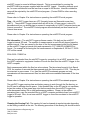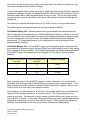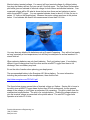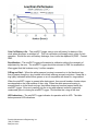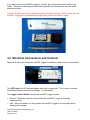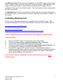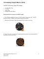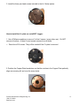
1
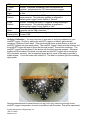
Precision Measurement Engineering, Inc. • www.pme.com
User’s Manual
2014
Precision Measurement Engineering, Inc.
(760) 727-0300
www.pme.com
1
Warranty
1-YEAR LIMITED WARRANTY ON miniDOT HARDWARE
Precision Measurement Engineering, Inc. (PME) warrant that the miniDOT Logger shall be
free of defects in workmanship and materials, under normal use, for a period of one year
from the date of shipment. This warranty is made only to the original purchaser. In the event
a miniDOT Logger covered by this warranty fails to operate according to our published
specifications, then return it freight pre-paid to PME or an authorized Service Provider. PME
will repair the unit at no charge to the customer and bear the cost of return shipment.
Carefully pack all components, as the customer is responsible for any freight damage.
This warranty does not apply to services or consumable / expendable items (such as
batteries, fuses and ropes) required for general maintenance. Equipment manufactured by
other companies (such as meteorology sensors, solar panels, etc) are warranted only to the
limit of the warranties provided by their original manufacturer.
PME makes no warranty, either expressed or implied, that the sensors will be operable after
they are exposed to adverse environmental conditions, such as bio-fouling, oil fouling,
freezing temperatures or others.
This warranty is void if, in our opinion, the miniDOT Logger has been damaged by accident,
mishandled, altered, or repaired by the customer, where such treatment has affected its
performance or reliability. In the event of such treatment by the customer, costs for repairs
plus two-way freight costs (no COD shipments will be accepted) will be borne by the
customer. In such cases, an estimate will be submitted for approval before repair work is
started. Items found to be defective should be returned to PME carefully packed, as the
customer will be responsible for freight damage.
Incidental or consequential damages or costs incurred as a result of the product malfunction
are not the responsibility of PME.
For all warranty or non-warranty returns please obtain, complete, and submit a RMA to PME.
This RMA form may be obtained at
http://www.pme.com/HTML%20Docs/RMAform.html.
After submission of this form, then PME will respond with a RMA number. Please place this
number on all shipments and related communications.
Precision Measurement Engineering, Inc.
(760) 727-0300
www.pme.com
2
Safety Information
BURSTING HAZARD
Should water enter the miniDOT Logger and come into contact with the enclosed batteries,
then the batteries may generate gas, causing the internal pressure to increase. This gas will
likely exit via the same location where the water entered, but not necessarily. The miniDOT
Logger is designed to release internal pressure, as the black end cap is unscrewed, prior to
the disengagement of the black end cap threads. If internal pressure is suspected, then treat
the miniDOT Logger with extreme caution.
Revision History
Date
2014JUN09
2014JUL01
2014JUL16
2014SEP24
2014NOV14
2014DEC17
2015JAN09
2015JAN23
2015FEB03
2015APR15
2015SEP11
2015SEP11
Revision Description
Initial Document, revised from 6881
Extensively Revised
Added Storage When Not in Use to sec 1.2
Added pictures, reworded. Removed wire mesh installation instructions
Added update Java instructions. Removed statement saying alkaline batteries
supplied.
Added 1 green flash for sample intervals of 1 minute or less
Minor revision
Added note about miniDOTPlot large sample sets
Modified battery endurance, modified wording, added # files warning
Added file upload to Android phone instructions
Added the Cu mesh / plate instructions
Updated wording to be consistent throughout manual
Precision Measurement Engineering, Inc.
(760) 727-0300
www.pme.com
3
CONTENTS
Chapter 1 Quick Start
1.1 The Quickest Start Possible
1.2 A Few Details
Chapter 2 Software
2.1
2.2
2.3
2.4
Overview and Software Installation
miniDOTControl
miniDOTPlot
miniDOTConcatenate
Chapter 3 miniDOT Logger
3.1 Overview
3.2 Opening and Closing the miniDOT
Logger
3.3 Electrical Connections and Controls
3.4 Battery Replacement
3.5 Installing Copper Mesh or Plate
Precision Measurement Engineering, Inc.
(760) 727-0300
www.pme.com
4
Chapter 1: Quick Start
1.1 The Quickest Start Possible
Your miniDOT Logger has arrived completely ready to go. It is set to measure and record
time, battery voltage, temperature, oxygen concentration, and measurement quality once
every 10 minutes and write one file of measurements daily. Open the miniDOT Logger and
move the Logger Control Switch to the “Record” position. In this condition, the miniDOT
Logger will record measurements for a year before the internal batteries are expended. You
must re-close the miniDOT Logger prior to deploying it.
At the end of the deployment period, open the miniDOT Logger and connect it to a HOST
computer via the USB connection. The miniDOT Logger will appear as a ‘thumb drive’. Your
temperature and oxygen concentration measurements, together with a time stamp indicating
the time the measurements were made, are recorded in text files in the folder having the
serial number of your miniDOT Logger. These files can be copied onto any Windows or Mac
HOST computer.
This Manual and other software programs are also recorded on the miniDOT Logger.
• miniDOTControl program allows you to see the state of the miniDOT Logger as well as
set the recording interval.
• miniDOTPlot program allows you to see the plots of the recorded measurements.
• miniDOTConcatenate program gathers all the daily files into one CAT.txt file.
Your miniDOT Logger will return to recording measurements after you disconnect the USB
connection. If you wish to stop recording, then move the Logger Control Switch to the “Halt”
position.
You may move the Logger Control Switch at any time.
Follow these steps to start the deployment, logging DO & T once each 10 minutes:
1) Open the miniDOT Logger by unscrewing the white pressure housing from the black end
cap. It opens like a flashlight. Remove the white pressure housing completely. Inside
you will see the circuit pictured below:
Precision Measurement Engineering, Inc.
(760) 727-0300
www.pme.com
5
2) Move the Logger Control Switch to the “Record” position. The LED will flash green 5
times. The miniDOT Logger will now record a measurement of time, battery voltage,
temperature, and dissolved oxygen every 10 minutes (or at some other interval you may
have set using the miniDOTControl program).
3) Inspect the o-ring seal for debris.
4) Close the miniDOT Logger by screwing the white pressure housing back onto the black
end cap.
5) Deploy the miniDOT Logger.
Follow these steps to end the deployment
1) Recover the miniDOT Logger
2) Clean and dry all accessible surfaces except the ‘sensing foil’.
3) Open the miniDOT Logger by unscrewing the white pressure housing from the black end
cap. Remove the white pressure housing completely, taking care that water does not drip
onto interior surfaces of circuits or other items inside the miniDOT Logger.
4) Connect to a Windows HOST computer via the USB connection. The miniDOT Logger
will appear as a ‘thumb drive’.
5) Copy the folder having the same serial number as the miniDOT Logger (example 73920001) to the HOST computer.
6) (Suggested, but optional) Delete the measurement folder, but NOT the miniDOTControl
program or the other .jar programs.
7) (Optional) Run the miniDOTControl program to see the state of the miniDOT Logger such
as battery voltage or to select a different recording interval.
8) (Optional) Run the miniDOTPLOT program to see a plot of measurements.
9) (Optional) Run the miniDOTConcatenate program to gather together all the daily files of
measurements into one CAT.txt file.
10) If no more recording is desired, then move the Logger Control Switch to “Halt”, otherwise
leave it set to “Record” to continue recording measurements.
11) Disconnect the miniDOT Logger from the USB connection.
12) Inspect the o-ring seal for debris.
13) Close the miniDOT Logger by screwing the white pressure housing back onto the black
end cap.
Remove the batteries if storing the miniDOT Logger for extended periods.
1.2 A Few Details
The previous section gives instructions for sampling at 10-minute intervals. However, there
are a few additional details that will enhance use of the miniDOT Logger.
Recording Interval – The miniDOT Logger measures and records time, battery voltage,
temperature, dissolved oxygen concentration and measurement quality at equal time
intervals. The default time interval is 10 minutes. However, it is also possible to instruct the
Precision Measurement Engineering, Inc.
(760) 727-0300
www.pme.com
6
miniDOT Logger to record at different intervals. This is accomplished by running the
miniDOTControl.jar program supplied with the miniDOT Logger. Recording intervals must
be 1 or more minutes and must be less than or equal to 60 minutes. Intervals outside this
range will be rejected by the miniDOTControl program. (Contact PME for other recording
intervals.)
Please refer to Chapter 2 for instructions on operating the miniDOTControl program.
Time – All miniDOT Logger times are UTC (formerly known as Greenwich mean time
(GMT)). The miniDOT Logger internal clock will drift in the <10 ppm range (< about 30
seconds/month) so you should plan to connect it occasionally to a HOST computer having an
Internet connection. The miniDOTControl program will automatically set time based on an
Internet time server.
Please refer to Chapter 2 for instructions on operating the miniDOTControl program.
File Information – The miniDOT Logger software creates 1 file daily on the miniDOT
Logger’s internal SD card. The number of measurements in each file will depend upon the
sample interval. Files are named by the time of the first measurement within the file based
on the miniDOT Logger’s internal clock and expressed in YYYY-MM-DD HHMMSSZ.txt
format. For example a file having the first measurement on September 9, 2014 at 17:39:00
UTC will be named
2014-09-09 173900Z.txt.
Files can be uploaded from the miniDOT Logger by connecting it to a HOST computer. Use
the HOST computer’s copy/paste functions to move the files from the miniDOT Logger to the
HOST computer.
Each measurement within the files has a time stamp. The time stamp format is Unix Epoch
1970, the number of seconds that have passed since the first moment of 1970. This may be
inconvenient in some cases. If so, then the miniDOTConcatenate program not only
concatenates all the measurement files, but also adds more readable statements of the time
stamp.
Please refer to Chapter 2 for instructions on operating the miniDOTConcatenate program.
The miniDOT Logger requires time and battery energy to work through the file directory on
the SD card to allocate new file space. A few hundred files on the SD card is not a problem,
but as the number of files grows large into the thousands then the miniDOT Logger may
suffer decreased battery life or other performance problems. Please, at the earliest
convenient time, copy the recorded files to a HOST computer and delete them from miniDOT
Logger’s SD card. Also, do not use miniDOT Logger to store files unrelated to the miniDOT
Logger’s operation.
Cleaning the Sensing Foil –The sensing foil can be cleaned at regular intervals depending
on the fouling condition at the site. The cleaning procedure of the sensing foil should be done
Precision Measurement Engineering, Inc.
(760) 727-0300
www.pme.com
7
with caution so that the protective coating is not removed. If the fouling is calcareous it can
normally be dissolved with household vinegar.
If the marine growth remains, then use Q-tips to gently wipe the sensing foil after it has been
softened by soaking in vinegar or perhaps diluted HCl. After cleaning the sensing foil, then it
should be rinsed well in clean tap water before storing or reuse. Do not use other organic
solvents such as acetone, chloroform, and toluene since these and others will damage the
sensing foil.
The sensing foil can also be cleaned using a 3% H2O2 solution or rinsing it with ethanol.
The white pressure housing and black end cap can be gently scrubbed.
AA Alkaline Battery Life – Alkaline batteries will give somewhat less performance than
lithium, especially at low temperatures. Alkaline batteries are superior to lithium in one way:
you can determine how much battery life remains by measuring the battery terminal voltage.
For short deployments of a month or two, then alkaline batteries will provide adequate
performance. For longer deployments, or for deployments in cold environments, then
substitute lithium batteries.
AA Lithium Battery Life – The miniDOT Logger consumes battery power mostly from the
measurement of dissolved oxygen, but also slightly from simply keeping track of time, writing
files, sleeping, and other activities. The following table shows the approximate endurance of
the miniDOT Logger when powered by the Energizer L91 AA lithium / ferrous disulfide
batteries:
SAMPLE INTERVAL
(minutes)
Main AA Battery Life
(months)
Number of Samples
1
12
500K
10
>12
>52,000
60
>12
>8,000
Keep a general record of the miniDOT Logger’s number of samples. It is not possible to
accurately tell the charge state of a lithium battery by measuring its terminal voltage. If you
have a general idea of the number of samples already obtained on a battery, then you can
make a guess as to how many more samples remain.
The numbers in the table above are, at the time of this writing, based upon extrapolations of
testing of 500K samples acquired at a 5-second interval. The 1-year performance at 1
minute is very likely. Performance at longer sample intervals will be much longer, but how
long is difficult to predict. In any event, these AA batteries are easily available and relatively
inexpensive compared to the cost of the miniDOT Logger. PME suggests you replace the
batteries often, especially before any long (months) measurement deployments.
Precision Measurement Engineering, Inc.
(760) 727-0300
www.pme.com
8
Monitor battery terminal voltage. You cannot tell from terminal voltage of a lithium battery
how long the battery will last, but you can tell if it will die soon. The Low Drain Performance
plot below gives an estimate of terminal voltage for both lithium and alkaline batteries. Your
measured voltage will be 2X what is shown below since there are two batteries in series
within the miniDOT Logger. You can operate batteries down to about 2.4 Volts (for two in
series, 1.2 Volts on the graph below). Measure the series voltage as shown in the picture
below. Your batteries are dead if this measurement is less than 2.4 Volts.
You may also use alkaline AA batteries such as Duracell Coppertop. They will not last nearly
as long, especially at low temperatures, but will likely be adequate for several weeks at 10minute interval.
When replacing batteries use only fresh batteries. Don’t mix battery types. If one battery
differs in type or charge level from the other and the miniDOT Logger runs them to full
discharge, then one battery may leak.
Err on the side of caution when planning your deployment.
The recommended battery is the Energizer L91 lithium battery. For more information
including the performance at low temperatures, then click the link:
http://data.energizer.com/PDFs/l91.pdf
The figure below gives a general idea of terminal voltage vs. lifetime. Service life in hours is
incorrect since miniDOT Logger draws far less than 50 mA continuously, but the general
shape of the voltage vs. time gives an estimate of life remaining. This plot is taken from the
manufacturer’s specification. The plot is for a single battery. Double the voltages shown to
give the terminal voltage as measured in the picture above. The miniDOT Logger halts
operation at a total of 2.4 Volts.
Precision Measurement Engineering, Inc.
(760) 727-0300
www.pme.com
9
Coin Cell Battery Life – The miniDOT Logger uses a coin cell battery for backup of the
clock when the power is switched off. This coin cell battery will supply many years of clock
operation. Should the coin cell battery discharge, then it must be replaced by PME. Contact
PME.
Recalibration – The miniDOT Logger will maintain its calibration without the necessity of
adjustment by the user. The miniDOT Logger should be returned to PME for recalibration.
We suggest that this be done every ½ million samples.
O-Ring and Seal – When the white pressure housing is screwed on to the black end cap,
then it passes along the o-ring located in the black end cap several revolutions. Keep this oring lightly lubricated with silicone grease or an oil compatible with buna-N o-ring material.
When the miniDOT Logger is opened after deployment, then a small number of water drops
are deposited on the inner surface of the o-ring. When the white pressure housing is
screwed back on to the black end cap, then these drops can become trapped inside the
miniDOT Logger. Be sure to carefully dry the o-ring and adjacent surfaces (especially
underneath) prior to closing the miniDOT Logger. Re-lubricate the o-ring at this time.
LED Indications – The miniDOT Logger indicates its operation with its LED. The table
below presents LED indications:
Precision Measurement Engineering, Inc.
(760) 727-0300
www.pme.com
10
LED
1 Green
Flash
1 Green
Flash
5 Green
Flashes
5 Red
Flashes
Continuously
Green
Continuously
Flashing Red
Reason
Normal. Presented immediately after new batteries are
installed. Indicates that the CPU has started its program.
Occurs at the time of sampling for sample intervals of 1 minute
or less.
Normal. Indicates that miniDOT Logger is beginning to record
measurements. This indication appears in response to
switching the Logger Control Switch to “Record.”
Normal. Indicates the miniDOT Logger is ending recording of
measurements. This indication appears in response to
switching the Logger Control Switch to “Halt.”
Normal. Indicates the miniDOT Logger is connected to a HOST
computer via the USB connection.
SD card write error. Try removing/reinstalling batteries.
Contact PME.
Verifying Calibration – You may from time to time want to verify the calibration of your
miniDOT Logger. Do this by placing the miniDOT Logger in a black 5-gallon bucket
containing 4 gallons of fresh water. (The picture below shows a white bucket so that the
miniDOT Loggers are more easily seen.) The miniDOT Logger’s black end cap is heavy and
the miniDOT Logger will tend to flip so that this end is down. Prevent this somehow. The
miniDOT Logger must be placed in the bucket with the black end cap upwards. Otherwise
bubbles will accumulate in the black end cap area and miniDOT Logger will not sense the
DO in the water correctly. Use an aquarium pump and air stone in the water to provide a
bubble stream. Cover the bucket with a black lid. The idea is to prevent light from enabling
algal growth.
Record measurements for several hours or a day, but in any event long enough for the
miniDOT Logger’s temperature to come to equilibrium with the water. During the experiment,
Precision Measurement Engineering, Inc.
(760) 727-0300
www.pme.com
11
find the local air pressure, either from measurements or from a local weather station. Watch
out... weather stations often report barometric pressure referenced to sea level. You must
determine the absolute barometric pressure at your elevation.
A more comprehensive experiment is to additionally place ice in the bucket and mix until the
water temperature is close to zero degrees. Next, remove the ice. Place the bucket on a
towel or piece of cardboard and cover the top of the bucket with a towel. Record for 24 hours
as the bucket temperature gradually returns to room temperature.
After recording the bubbled water, you may also remove the air stone and gently mix a
packet of baker’s yeast into the bucket together with a tablespoon of sugar. The water must
be only slightly warm to the touch but not more than 30 deg C. These organisms will deplete
all the dissolved oxygen in the water. Cut a disc of thin plastic film just large enough to lay
on top of the water. Place this on top of the water. Do not stir or bubble after placing the
film. Record measurements for at least an hour or more.
Use the miniDOT Logger’s miniDOTPlot program to examine the measurements. Saturation
values should be very close to 100%, depending upon the accuracy that you have
determined barometric pressure. If you placed ice in the bucket, then saturation values will
still be 100%. You will see the DO concentration and temperature change greatly as the
bucket warms.
The recorded data, when using yeast should show 0% saturation and 0 mg/l dissolved
oxygen concentration. In practice the miniDOT Logger often reports slightly positive values
of about 0.1 mg/l, but within the accuracy of the miniDOT Logger.
Closing and Opening – Close and open the miniDOT Logger like you would a flashlight;
open by unscrewing the white pressure housing from the black end cap. Close by screwing
the white pressuring housing on to the black end cap. When closing, do not tighten the
white pressure housing. Just screw it on until it makes contact with the black end cap. See
Chapter 3 for more instructions.
Caution: DO NOT remove the stainless steel screws in the black end cap. There are no
user serviceable parts here. If the screws are removed, then you will damage the miniDOT
Logger and it will have to be returned for repair.
Storage When Not in Use – Remove the batteries. Keep the black end covered with the
cap supplied by PME. If the cap is lost, then cover the black end cap with aluminum foil.
There may be a calibration effect of ambient lighting so attempt to keep ambient light from
reaching the sensing foil as much as possible.
Java – miniDOT programs depend on Java and require Java 1.7 or higher. Update Java at
https://java.com/en/download/index.jsp
Upload Files to an Android device – It is possible to transfer your measurement files from
the miniDOT Logger to your Android device. This operation has 3 prerequisites.
1. An Android device equipped with USB On-The-Go (OTG) feature. OTG is a feature for
most modern Android devices that allow them to act as a USB host. OTG was introduced
Precision Measurement Engineering, Inc.
(760) 727-0300
www.pme.com
12
with Android version 3.1 and should be a useable feature for most devices. It is still
possible that your device doesn't support OTG. Please test your device with a miniDOT
Logger prior to attempting to upload while in the field.
2. A USB OTG cable. This is essentially an adapter with a micro USB connector on one end
that connects to your Android device and a standard A type USB plug on the other. The
cable supplied with the miniDOT Logger connects to this end.
3. A "File Explorer" app downloaded on your Android device. These types of apps assist
with being able to view and move files from device to device. "ES File Explorer" is a free
app available on the Google app store and is recommended for use with the miniDOT
Logger.
If the 3 requirements are met, then connect the miniDOT Logger to your Android device. You
should see the miniDOT Logger’s green connection light come on and your Android device
will display a message about "preparing USB storage". When "USB storage ready" is shown,
then use your "file explorer" program to move your data from the miniDOT Logger onto your
Android device.
Again, it is highly recommended that you try this operation at your workstation prior to
depending upon this in the field.
Currently the associated miniDOT Logger programs: miniDOTControl, miniDOTPlot, and
miniDOTConcatenate are not supported by the Android devices.
Precision Measurement Engineering, Inc.
(760) 727-0300
www.pme.com
13
Chapter 2: Software
2.1 Overview and Software Installation
The miniDOT Logger arrives with these files on the SD card:
•
•
•
•
miniDOTControl.jar program allows you to see the state of the miniDOT Logger as well
as set the recording interval.
miniDOTPlot.jar program allows you to see the plots of the recorded measurements.
miniDOTConcatenate.jar program gathers all the daily files into one CAT.txt file.
Manual.pdf is the manual.
These files are located on the root directory of the miniDOT Logger.
PME suggests you leave these programs where they are on the miniDOT Logger, but you
may copy them to any folder on your HOST computer’s hard drive.
miniDOTControl, miniDOTPlot, and miniDOTConcatenate programs are Java language
programs that require the HOST computer to have the Java Runtime Engine V1.7 (JRE) or
later versions installed. This engine is commonly required for Internet applications and will
likely already be installed on the HOST computer. You can test this by running the
miniDOTPlot program. If this program displays its graphical user interface, then the JRE is
installed. If not, then the JRE can be downloaded via the Internet from
http://www.java.com/en/download/windows_xpi.jsp
At this time the miniDOT Logger is supported on the Windows operating systems, but may
also operate on Macintosh and perhaps Linux.
2.2 miniDOTControl
Begin program operation by clicking “miniDOTControl.jar”. The program presents the screen
shown below:
Precision Measurement Engineering, Inc.
(760) 727-0300
www.pme.com
14
The miniDOT Logger must be connected to the HOST computer via the USB connection at
this time. When correctly connected, the miniDOT Logger’s LED will display a constant
green light.
Click the “Connect” button. The program will contact the miniDOT Logger. If the connection
is successful, then the button will turn green and display “Connected”. The Serial Number
and other parameters will be filled in from the information taken from the miniDOT Logger.
If the HOST computer is connected to the Internet, then the current difference between an
Internet time server’s time and the miniDOT Logger’s internal clock will be displayed. If more
than a week has passed since time was last set, then the miniDOT Logger’s clock will be set
and the checkmark icon will appear. If the HOST computer is not connected to the Internet,
then no time services will occur.
The current miniDOT Logger’s sample interval will be displayed next to the “Set Sample
Interval” button.
Precision Measurement Engineering, Inc.
(760) 727-0300
www.pme.com
15
To set the interval, enter an interval not less than 1 minute and not greater than 60 minutes.
Click the “Set Sample Interval” button. Shorter and faster intervals are available. Contact
PME.
If this interval is acceptable, then the interval need not be set.
End the miniDOTControl program by closing the window. Disconnect the miniDOT Logger’s
USB cable.
Upon disconnection of the USB cable, the miniDOT Logger will begin logging or remain
halted as indicated by the position of the Logger Control Switch.
2.3 miniDOTPlot
Begin the program operation by clicking “miniDOTPlot.jar”. The program presents the screen
shown below.
The miniDOTPlot program plots the files recorded by the miniDOT Logger. The program
reads all the miniDOT Logger files in a folder, except the CAT.txt file. The program will also
compute oxygen saturation from the dissolved oxygen measurements. To do this, the
program must know the air pressure and salinity. It calculates air pressure based on
elevation of the water surface above sea level or uses the barometric pressure you enter if
Barometric Pressure is selected. If the Surface Elevation is entered, then no compensation
for weather-induced barometric pressure variation is made. Enter elevation or barometric
pressure. Enter water salinity.
Select the folder that contains the files recorded by the miniDOT Logger. If the miniDOTPlot
program is run directly from the miniDOT Logger, then the program will suggest the folder
that is located on the miniDOT Logger’s SD card. You may accept this by clicking “Plot”, or
you may click “Select DATA Folder” to browse to your HOST computer’s hard drive. If the
number of measurements recorded is small, for example a few thousand, then these can
conveniently be plotted directly from the miniDOT Logger’s storage. However, it is best to
copy large measurement sets to the HOST computer and select them there. The file access
to the miniDOT Logger is slow.
Precision Measurement Engineering, Inc.
(760) 727-0300
www.pme.com
16
The miniDOT Logger’s measurement folders must NOT contain any files besides those the
miniDOT Logger recorded and the CAT.txt file.
Click “Plot” to begin plotting.
The program reads all the miniDOT Logger’s data files in the selected folder. It concatenates
these and presents the plot shown below
You may zoom this plot by drawing a square from upper left to lower right (click and hold left
mouse button) that defines the zoom region. To zoom completely out, attempt to draw a
square from lower right to upper left. Right click on the plot for options such as copy and
print. The plot can be scrolled with the mouse while the Control key is held depressed.
Copies of the plot can be obtained by right clicking on the plot and selecting Copy from the
pop-up menu.
Different DATA Folders can be selected during one session of the program. In this case the
software produces multiple plots. Unfortunately, the plots are presented exactly on top of
one other and so when a new plot appears it is not obvious that the old plot is still there. It is.
Just move the new plot to see previous plots.
The program can be re-run at any time. If an already processed DATA Folder is selected,
then the progrm simply reads the miniDOT Logger’s measurement files again.
End the miniDOTPlot program by closing the window.
Special note: plotting of sample sets of more than 200K samples may consume all the
memory available to the JRE. The miniDOTPlot program will present a partial plot and
Precision Measurement Engineering, Inc.
(760) 727-0300
www.pme.com
17
freeze in this case. A simple solution is to separate the files into multiple folders and plot
each folder individually. A special miniDOTPlot that sub-samples can be provided by PME.
Please contact PME in this case.
2.4 miniDOTConcatenate
Begin the program operation by clicking “miniDOTConcatenate.jar”. The program presents
the screen shown below.
The miniDOTConcatenate program reads and concatenates the files recorded by the
miniDOT Logger. This program produces a CAT.txt file in the same folder as selected for the
data. The CAT.txt file contains all the original measurements and contains two additional
statements of time and oxygen saturation. To compute saturation, the program must know
the air pressure and salinity. It calculates air pressure based on elevation of the water
surface above sea level or uses the barometric pressure you entered if the Barometric
Pressure was selected. If Surface Elevation is entered, then no compensation for weatherinduced barometric pressure variation is made. Enter elevation or barometric pressure.
Enter water salinity.
Select the folder that contains the files recorded by the miniDOT Logger. If the miniDOTPlot
program is run directly from the miniDOT Logger, then the program will suggest the folder
located on the miniDOT Logger. You may accept this by clicking “Concatenate”, or you may
click “Select DATA Folder” to browse your HOST computer’s hard drive. If the number of
measurements recorded is small, for example a few thousand, then these can conveniently
be plotted directly from the miniDOT Logger’s storage. However it is best to copy large
measurement sets to the HOST computer and select them there. The file access to the
miniDOT Logger is slow.
The miniDOT Logger measurement folders must NOT contain any files besides those the
miniDOT Logger recorded and the CAT.txt file.
Click “Concatenate” to begin concatenating files and create the CAT.txt file.
The CAT.txt file will resemble the following:
Precision Measurement Engineering, Inc.
(760) 727-0300
www.pme.com
18
End the miniDOTConcatenate program by closing the window.
Chapter 3: miniDOT Logger
3.1 Overview
All miniDOT Logger measurements are saved in files on the SD card inside the miniDOT
Logger. The files are transferred to a HOST computer via a USB connection where the
miniDOT Logger appears as a “thumb drive”. Measurements may be plotted by the
miniDOTPlot program and files concatenated by the miniDOTConcatenate program. The
miniDOT Logger itself is controlled by the miniDOTControl program. Customers are
required to open the logger each time measurements are transferred to the HOST computer.
This chapter describes the miniDOT Logger’s internal features.
3.2 Opening and Closing the miniDOT Logger
The miniDOT Logger’s circuitry is contained in a waterproof housing that must be opened.
Unscrewing the white pressure housing from the black end cap opens the miniDOT Logger.
This is similar to opening a flashlight. Turn the white pressure housing counter clockwise
relative to the black end cap. Close the miniDOT Logger by reversing this procedure after
being sure that the o-ring is free from debris. Lubricate the o-ring occasionally with silicone
oil intended for buna-N o-ring material.
Please attempt to handle the miniDOT Logger by only touching the aluminum chassis. Try
not to touch the circuit board.
When closing the miniDOT Logger, inspect the o-ring and the interior of the white pressure
housing for debris. Lubricate the o-ring, and screw the white pressure housing onto the black
end cap until the white pressure housing just touches the black end cap. Do not tighten! The
miniDOT Logger tends to get a little tighter during deployment.
Precision Measurement Engineering, Inc.
(760) 727-0300
www.pme.com
19
If you cannot open the miniDOT Logger by yourself, then find another person with strong
hands. This person should grip the black end cap while the other person turns the white
pressure housing.
Caution: Do NOT remove the stainless screws in the black end cap. If this is done, then the
miniDOT Logger will be permanently damaged and must be returned for repair.
3.3 Electrical Connections and Controls
Removal of the cover reveals the miniDOT Logger’s connections and controls, shown below.
The LED Light is a LED that can display either red or green light. This is used to indicate
the different features described in Chapter 1 in this manual.
The Logger Control Switch controls the miniDOT Logger’s mode:
•
•
Record – When the switch is in this position the miniDOT Logger is recording
measurements.
Halt – When the switch is in this position the miniDOT Logger is not recording and is
sleeping at low power.
Precision Measurement Engineering, Inc.
(760) 727-0300
www.pme.com
20
The USB Connection allows communication between the miniDOT Logger and an external
HOST computer. When connected, the miniDOT Logger is in HALT mode regardless of the
Logger Control Switch position. When disconnected, the miniDOT Logger’s mode is
controlled by the Logger Control Switch position. The switch position may be changed while
the USB is connected.
The Main Batteries (2 X AA on side opposite to pictured side above) provide main power to
the miniDOT Logger. Note the positive (+) terminal. Batteries are described in Chapter 1 of
this manual.
3.4 Battery Replacement
Be sure that the replacement batteries are compatible with the miniDOT Logger. PME
recommends Energizer L91 AA size lithium batteries or Duracell AA size alkaline batteries.
http://data.energizer.com/PDFs/l91.pdf
http://ww2.duracell.com/media/enUS/pdf/gtcl/Product_Data_Sheet/NA_DATASHEETS/MN1500_US_CT.pdf
Caution: Improper replacement of the batteries will damage the miniDOT Logger.
Follow these steps:
1)
2)
3)
4)
5)
Move the miniDOT Logger’s Control Switch to the “Halt” position.
Remove the depleted batteries noting the position of the (+) terminal.
Use only new, fully charged batteries, both of the same type.
Install fresh batteries with the (+) position the same as the removed batteries. The
(+) position is also marked on the inside of the battery holder.
The miniDOT Logger’s LED Light should flash to indicate that the software is
beginning operation within a second or two after you complete the battery installation.
At this time the logger will enter the mode selected by the Logger Control Switch
(which should initially be “Halt” from Step 1).
If you install the batteries backwards, then you should plan to purchase a new
miniDOT Logger.
Precision Measurement Engineering, Inc.
(760) 727-0300
www.pme.com
21
3.5 Installing Copper Mesh or Plate
miniDOT Anti-Fouling Copper Kit includes:
•
•
•
•
1 Cu Wire Mesh Disc
1 Cu Plate
1 Nylon Ring
6 Phillips Pan Head Screws
How to install the Cu mesh on a miniDOT Logger:
1. Use a Phillips screwdriver to remove 3 of the 6 screws (every other one). Do NOT
remove all screws. At least 3 must remain screwed in at all times.
•
Save the ss316 screws. They will be needed if the Cu mesh is removed.
2. Position the nylon ring under the Cu mesh so that the notches in the nylon ring and Cu
mesh align over the screw holes.
Precision Measurement Engineering, Inc.
(760) 727-0300
www.pme.com
22
3. Install the three pan head screws included in the kit. Gently tighten.
How to install the Cu plate on a miniDOT Logger:
1. Use a Phillips screwdriver to remove 3 of the 6 screws (every other one). Do NOT
remove all screws. At least 3 must remain screwed in at all times.
•
Save the ss316 screws. They will be needed if the Cu plate is removed.
2. Position the Copper Plate faced down so that the notches in the Copper Plate perfectly
align over sensing foil and over the screw holes.
Precision Measurement Engineering, Inc.
(760) 727-0300
www.pme.com
23
4. Install the three pan head screws included in the kit. Gently tighten.
Enjoy your new miniDOT!
Precision Measurement Engineering, Inc.
(760) 727-0300
www.pme.com
24