1
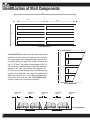
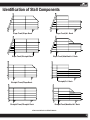
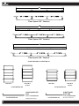
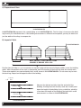
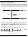
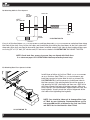
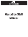
Gestation Stall
Manual
Identification of Stall Components
209’
3’
3’
100’
41’
50) 24” stalls
3’
100’
ILLUSTRATION 1A
Feeding Alley
3’
Feeding
alley
Our example building has eight rows of 50
3
stalls that are 24” wide. The length of the
ILLUSTRATION
1A is
planare
of three
a typical
building is 209’
IDfloor
and there
alley-gestation 7
building
that
serve
an example
of the
ways
36”will
wide.
Theas
width
of the building
is installaID. Therestalls
are two
36”feeding
lotion of41’
gestation
through
out alleys
this manual.
Our2
cated
along
the
outside
and
another
36”
alley
example building has eight rows of 50 stalls that are
down the middle. In addition there are two
7
24” x 24”
7’0”access
long.alleys
The length
ofthe
theback
building
located at
of the is 209’ ID
(ID stands
Dimension) and there are three3
stalls for
overInside
the slats.
alleyways 36” wide. The width of the building is 41’ 7
ID. There are two 36”feeding alleys located along the
2
outside and another 36” alley down the middle. In addition there are two 24” access alleys located at the
7
back of the stalls over the slats. ILLUSTRATION 1B
and 1C are close-ups of top and side views.
3
7’
2’
Access
alley
Access Alley
7’
Feeding
alley
Feeding Alley
3’
7’
Access
2’ alley
Access Alley
7’
Feeding alley
3’
Feeding Alley
ILLUSTRATION 1B
3’
Feeding
Alley
3’ Feeding
Alley
2’
Access
2’ Alley
Access
3’
Feeding
Alley
3’ Feeding
Alley
Alley
2’
Access
Alley
2’ Access
Alley
7’
7’
7’
7’
3’
Feeding
3’ Feeding
Alley
7’
Alley
7’
7’
7’
ILLUSTRATION 1C
Slats
Slats
1
Slats
Slats
Identification of Stall Components
Slope Front/A.I. Back
Slope Front/Slope Back
Slope Front/Straight Back
Slope Front/Modified A.I. Back
Straight/A.I. Back
Straight Front/Slope Back
Straight Front/Straight Back
Straight Front/Modified A.I. Back
STALLS SIDES ILLUSTRATION 2A
2
Floor Spacer (23” Centers)
Floor Spacer (24” Centers)
Floor Spacer (26” Centers)
FLOOR SPACER ILLUSTRATION 3A
Front Door
Front Door
Rear Door
Rear Door
(w/ pipe)
(w/ pipe)
ILLUSTRATION 3C
ILLUSTRATION 3B
SHORT DOOR
GATE ROD
LONG DOOR GATE
ROD
ILLUSTRATION 3D
3
PART # 5000100100
24 5/8” below bend
PART # 1000100100
ILLUSTRATION 3E
19 3/4” below bend
Top Spacer (23” Centers)
Top Spacer (24” Centers)
Top Spacer (26” Centers)
TOP SPACER ILLUSTRATION 4A
1/4” V-BOLT
PART # 60647
Gestation Top Spacer
Connectors
PART # 5000920100
ILLUSTRATION 4B
ILLUSTRATION 4C
CAST T-BOLT
PART # 309045100
1) 3090700000 CAST IRON TEE ONLY
1) 60831 SS BOLT 1/2” X 4 1/2”
1) 60583 1/2” SS FLAT WASHER
ILLUSTRATION 4E
1/4” locknut
PART # 60680
ILLUSTRATION 4D
STAINLESS STEEL
T-BOLT
PART # 3090100500 S.S. T-BOLT
1) 3090441500 1/2” x 5 1/2” Stainless STEEL T-BOLT
1) 60583 SS FLAT WASHER
1) 60693 ss LOCK NUT
ILLUSTRATION 4F
4
A) Preparation of Barn
ILLUSTRATION 5A
The is
first
is to measure
the building
to verify
its inside
dimensions.If the
If the
building
The first step
tostep
measure
the building
to verify
its inside
dimensions.
building
is the
different
expected,
may be able to
alleys to the buildILLUSTRATION measurement
5A represents
samethan
building
as in you
ILLUSTRATION
1Aadjust
. The the
firstwidth
step of
is the
measure
measurement is different than expected, you may be able to adjust the width of thetoalleys
to
compensate.
ing to verify its inside
dimensions. If the building measurement is different than expected, you may be able to ad-
compensate.
just the width of the alleys to compensate.
B) Layout of Stalls
The first step is to measure the building to verify its inside dimensions. If the building
measurement is different than expected, you may be able to adjust the width of the alleys to
compensate.
NOTE: CORRECT LOCATION OF FLOOR
SPACERS IS BEHIND STALL LEG
A
A
A
A
ILLUSTRATION 5B
B
B
in place laying out the correct alleyway widths across the building
Position two stall sides
width.. Position
After two
thestalls
position
of the
stalls
determined,
mark
the
location of the front legs from the outside walls.
sides in place
laying
out theis
correct
alleyway widths
across
the building
Position
two
stalls
sides
in
place
laying
out
the
correct
alleyway widths
thenecessary
building to mark
B
width.. After the position
the stalls is determined,
markAthe
location
of the front
from the
These measurements
areofrepresented
by the
and
B arrows
inlegs
ILLUSTRATION
5B.across
It is not
width..
After
position
ofbythe
stalls
determined,
mark
outside walls.
These measurements
are
represented
A and Bis
arrows
in the drawing.
It is the location of the front legs from the
the back
legs. Repeat
on
the the
opposite
side
ofthethe
building.
B
(see p.2 ILLUSTRATION
2A)
not necessaryoutside
to mark the
back legs.
Repeat
on the opposite sideare
of the
building.
walls.
These
measurements
represented
by the A and B arrows in the drawing. It is
Position two stalls sides in place laying out the correct alleyway widths across the building
not necessary to mark the back legs. Repeat on the opposite side of the building.
3’ end alley
width..
After the position of the stalls is determined, mark the location of the front legs from the
outside walls. These measurements are represented by the A and B arrows in the drawing. It is
3’ end alley
Measure the desired end alley
not necessary to mark the back legs. Repeat on
the opposite side of the building.
from the end wall of the buildA
ing. Starting from this location,
Chalk lines
3’ end alley
B
B
A
Chalk lines
A
A
5
B
Chalk lines
B
Chalk lines
ILLUSTRATION
5C
B
Chalk lines
A
Measure
theB point
desired
mark the A and
down end alley from the end wall of the
Measure the
desired
the length ofStarting
the building.from
Us- this location,
building.
mark
the Aend
andalley
B point
ing a chalk line, establish a line
from
the
end
wall
of
the
builddown
the
length
of the building. Using a chalk line, establish
down the
length
of the buildStarting
for down
both the the
A andlength
B meas- of theing.
aings
line
buildings
forfrom
boththis
thelocation,
A and B
urement.
mark
the
A
and
B
point
down
Measure
the
desired
end
alley
measurement as shown in ILLUSTRATION 5C.
length
theof
building.
Usfromthethe
end of
wall
the building a chalk line, establish a line
ing. Starting from this location,
down the length of the buildmark
thefor
A both
and the
B point
ings
A anddown
B measthe length
of
the
building.
Usurement.
ing a chalk line, establish a line
down the length of the build-
C) Layout of Floor spacers (see p.3 ILLUSTRATION 3A)
Using a 100’ tape, mark the chalk line every 8 feet. ILLUSTRATION 6A shows the marking sequence on the chalk
line at 8’, 16’, 24’, 32’, 40’, 48’, until we reach the 100’ mark which is the beginning of the center alleyway. NOTE:
DO NOT MARK THE LINES WITH A SHORT 8’ TAPE MULTIPLE TIMES BUT INSTEAD USE A LONG TAPE. If
you mark the 8’ distance using a short tape, a mistake in marking will mean you have the wrong measurement for
the rest of the line. NOTE: USE THE 8’ MARKING SEQUENCE FOR 24” STALLS ONLY. For 23” stalls mark the
chalk line every 92”, for 26” stalls mark the chalk line every 104”
8’ mark
Start alley mark
16’ mark, etc.
Chalk Line A
Chalk Lines C
Chalk Line B
TOP VIEW
6A have a mark at 8’, 16’,
Using a 100’ tape, mark the chalk
lineFLOOR
every SPACERS
8 feet. InILLUSTRATION
our example we
24’, 36’, 42’, 48’, etc. until we reach the 100’ mark which is the beginning of the center alleyway.be necessary
DO NOT to
MARK
THE LINES
WITH
SHORT
TAPE
MULTIPLE TIMES
BUT
IN-Line A
It will
snap additional
chalk
lines (A
shown
as C8’
lines
in ILLUSTRATION
6A) across
from
STEAD
USE
A
LONG
TAPE.
If
you
mark
the
8’
distance
using
a
short
tape,
a
mistake
in
markto Line B to mark the starting position of the rear floor spacers. Place floor spacers along the chalk line locatinging
them
at the
every
8’ mark. Fasten
concrete
floor
using
three
willfirst
mean
youbeginning
have the and
wrong
measurement
for all
thethe
restspacers
of theto
line.
NOTE
USE
THE
8’ 1/2” x 2
3/4”concrete
anchors
on solid floors.
T-bolts
if mounting
to slatted
floors.
Next92”,
bring
space and
MARK FOR
24” STALLS
ONLY.UseFor
23” stalls
mark the
chalk line
every
forrear
26”floor
stalls
place
against
cross
marked
chalk
line
in
the
general
position
they
will
be
used
at.
Another
view
of
the
floor spacmark the chalk line every 104”
ers layout is shown in ILLUSTRATION 6B.
24” to
center
24” to
center
24” to
center
24” to
center
24” to
center
24” to
center
24” to
center
24” to
center
Front view
Stalls legs
Floor spacers
74” Long
Start alley mark
21” between
spacers
22” between
ends of spacers
8’ mark
FRONT VIEW FLOOR
SPACERS ILLUSTRATION 6B
16’ mark
Chalk line
6
D) Attaching Stalls to Floor Spacers
60583
60583
1/2”
1/2”FLAT
FLAT
WASHER
WASHER
STALL LEG
STALL
LEG
60683
60683
1/2”
LOCK
1/2”
LOCKNUT
NUT
60536
60536
1/2”
1/2” xX 111/2”
1/2” BOLT
BOLT
FLOOR
SPACER
ILLUSTRATION
ILLUSTRATION
7A 7A
* GALVANIZED
FLOOR SPACER
Carry in all the front doors (see p.3 ILLUSTRATION 3B) and long drop rods (see p3 ILLUSTRATON 3D) and place them along
FASTEN
FLOOR
SPACER
TO CONCRETE
WITH 60656
- 1/2” X 2 3/4”the
ANCHOR
the front of the stalls. Carry in *the
stall
sides
and
stand them
up installing
front doors to the stalls sides with
TO SLAT WITH T-BOLTS (SEE PAGE 100)
drop rods. After stall are stood in place with front doors installed, connect stall sides to front and back floor spacers using 1/2” x 1 1/2” bolt, 1/2” washer and 1/2” lock nut as shown in ILLUSTRATION 7A. DO NOT TIGHTEN.
NOTE: Check back floor spacers to assure they are aligned with Chalk lines
C as shown on page 6 ILLUSTRATION 6A before proceeding to next step.
E) Attaching Rear Floor Spacers to Slats
Install three of either (a Cast Iron T-Bolt (see p4 ILLUSTRATION
or a Stainless Steel T-Bolt (see p4 ILLUSTRATION 4E) per
back floor spacers to fasten them to slats as shown in ILLUSTRATION 7B. It will be necessary to drill new holes in
the floor spacers if the existing holes do not line up over a
slat opening. Drill 1/4” pilot holes and then use a 5/8” bit to
drill holes towards the ends of the floor spacers. After rear
floors spacers are fastened down, tighten both the front and
back leg bolts. Visually check the vertical alignment of the
stall sides after tightening the leg bolts.
4D)
NOTE: Care should be taken not to damage either type
of T-Bolt by over tightening. Recommendations are to
not exceed 60 foot lbs. of torque for the Cast Iron T-Bolt
and 50 Ft lbs. for the Stainless Steel T-Bolt.
ILLUSTRATION 7B
7
F) Installing Top Spacers (see p3 ILLUSTRATION 3B)
27”
10”
Locate third top spacer to
front side of center upright
ILLUSTRATION 8A
From the back of the feed pipe ,chalk line at 10” and 27” and against the middle upright to mark
the location of the top spacers. The chalk line will mark the position of the V-bolt as shown below.
ILLUSTRATION 8B
Start the end of the each run of top
spacers with a top spacer connector (see p.4
ILLUSTRATION 4B). There are always six top
spacer connectors per row of stalls no matter
how the long the row is. Three on each end.
ILLUSTRATION 8C
Place top spacers under the stall top
angle and secure with a 1/4” V-bolt (see
p.4 ILLUSTRATION 4D) and two 1/4” lock
nuts (see p.4 ILLUSTRATION 4C).
G) Installing Rear Doors
Bring in rear doors (see p3 ILLUSTRATION 3C) and short gate rods (see p3 ILLUSTRATION 3E). Attached rear doors to
stalls sides with two gate rods.
8