1
US006741270B1
(12) United States Patent
(10) Patent No.:
Rzepkowski et al.
(54)
US 6,741,270 B1
(45) Date of Patent:
SYSTEMS AND METHODS SCALING A
CAPTURED IMAGE USING
May 25, 2004
Bill Camarda et al, “Using MICROSOFT Word 97”, 1997,
QUE Corporation, p. 98—99, 107, 348—351.*
PREDETERMINED SCALE INFORMATION
(75) Inventors: Kristinn R. Rzepkowski, Rochester,
cued by exammer
NY (US); Rudolph A. Rodrigues,
Rochester’ NY (Us)
Primary Examiner—John Cabeca
(73) Assignee: Xerox Corporation, Stamford, CT
(Us)
Assistant Examiner—x' L'_Bau?ste_l
_
(74) Attorney, Agent, or Fzrm—Ol1ff & Berr1dge, PLC
(*)
(57)
Notice:
Subject to any disclaimer, the term of this
patent is extended or adjusted under 35
U‘SC' 154(k)) by 0 days‘
ABSTRACT
Convent1onally, text boxes are used to inform an image
capture device of the siZe of an area to Which a captured
image Will need to be scaled, When ?tting the captured
image into that area of the composite document. In contrast,
siZe selection systems, methods and graphical user inter
(21) Appl' NO': 09/487’273
(22) Filed:
Jan. 19, 2000
(51)
Int Cl 7
'
'
G06F 3/00_ G06F 3/14
""""""""""""""" "
_
’
_
faces alloW the user to select one of a number of predeter
_
mined sets of scale dimensions that the captured image is to
(52)
US‘ Cl‘ """"
45
be scaled to. The siZe selection systems, methods and
(58)
Field of Search
’
’
345/’660 661
345/665 667 668 764 810 835 840
graphical user interfaces provide an alternative method for
specifying the dimensions that a captured image is to be
841 843’ 846’_ 35é/401’ 442’ 443’ 448’
scaled to. In various exemplary embodiments of the siZe
449, 451, 468; 715/517, 521, 526
selection systems, methods and graphical user interfaces, an
image siZe tab of a graphical user interface for an image
(56)
References Cited
capture driver includes a scale portion. The scale portion, in
us‘ PATENT DOCUMENTS
addition to having a number of dimension boxes that allow
the user to directly input the desired dimensions to Which the
4,837,635 A * 6/1989 Santos ...................... .. 358/401
5,053,885 A * 10/1991 Telle .......... ..
358/449
5,212,568 A * 5/1993 Graves et a1- 358/449 X
Captured image is to be Scaled, also includes a dimension list
box. The dimension list box includes predetermined sets of
dimensions to Which the captured image can be scaled. In
53017036 A * 4/1994 Barret} et al'
358/448
various exemplary embodiments, the dimensions list box
5502577 A *
358/468
5,963,216 A
3/1996 Milckmlay et a1‘ "
* 10/1999
6,215,487 B1 *
Ch1arab1n1 et al.
..
includes as the predetermined sets sets of dimensions for
345/660
’
4/2001 Barrett et al. ............. .. 345/840
.
’.
.
.
Common Paper was and Sets of dlmenslons for dlfferent
paper orientations. The predetermined sets of dimensions
OTHER PUBLICATIONS
can also include sets of user-de?ned dimensions. These
“User’s Guide_HP D esks can H Microsoft Windows Ver_
sion”, Sep 1997, HeW1ett_PaCkard Company, p_ 4_71_*
user-de?ned dimensions alloW the user to specify the dimen
sions of an image area of a document that is often used.
“Professional Desktop Scanner User’s Manual” (Mac ver
sion), 1999, MacIntosh, pp. 20—21.*
9 Claims, 14 Drawing Sheets
4'10 584 5,50
5,69
I /
_FireStarTWAlNDriI1er I
File View Opliun? Help I
I
500 \‘ asicFeatures Imag Quality mageSize
56'\~4:1 Copy/Frame
5110 —»
crop
563 _,--—'OFHITIB
/
Mirror si
2
...I...I...I...I.!.i...I...I...I ..
E
'2
‘E
dAll values equal
5;
,~-—E Reduce/Enlarge -=——'
‘E
572 __,-’E Proportional
E
573 7-“-
‘E
m574 ———>
I;;
575 '1‘:
9;
577 /’
m:
576 /
E
578 /'
I
_
ILKILL'HELJ
430 /
I
:
Bottom:
567
579 /'
@
I
I
IEIIIEII
/
l:I
566 \_ \FQIIE
Left
_/
‘Ii
/
—
_
FlreStor IWAI N
Original on: 851111 in. mg. on:
11.5111 in.
Flle 5|“:
zooua|
U.S. Patent
FIG.
1
U.S. Patent
May 25,2004
Sheet 2 0f 14
US 6,741,270 B1
55w2mH1ou:E<”m?.:=
2SE5Qa:
3
N.OE
2N\
=o
N
_
\
v2
2N
\3wownN3
8\_\.as:52
/
\
\
I
\
\
/H
_582 >:
E532:;
52:322%2
E352 :
_
l_|.
_
_
_5E2:S;N
/m
_:8=5:m2 0m54z\c:E6m35S<\.1H
>
lI -
53as:
"~5E2m.a58:w
U.S. Patent
260
\
May 25,2004
263
262
. i
Flle
(058w
mquiran
,v THE APPLICATION DISPLAYS n'sown GUI
/Select
Source...
can Set-Up...
x THE APPLICATION REQUESTS THAT THE souRcE
Exit
MANAGER'S sELEcr souRcE DIALOG BOX APPEAR
(0R 0 MAY DISPLAY n's own VERSION). AFTER
THE USER SELECTS THE souRcE THEY WANT TO
265
\
THE APPLICATION REOUESTSTHAT THE souRcE PREPARE
T0 TRANSFER IMAGES. THERE ARE3 POSSIBLE MODES:
THE souRcE DISPLAYS IT'S sun FOR SCAN SETUP ONLY
//print
264 / prim Setup,"
234
USE, (ONTROLRETURNS TO THEAPPLICATION.
Select Source
SOURCE
MANAGER
X
Source
XBFOX FIreStar TWAIN
220
SOURCE
US 6,741,270 B1
THE souRcE DISPLAYS IT‘S GUI
\S§$Q--APPLIQATION -
Sheet 3 0f 14
SOURCE‘S USER
INTERFACE
>
FIRESTAR TWAIN
DRIVER
/
232
FIG. 3
235
U.S. Patent
May 25,2004
Sheet 4 0f 14
US 6,741,270 B1
wE5mEEsumw
{Eo.9m2-il0é
2mE262%m22N5:3m:..Sg6%x2%um9E965Faaoa>526m mE.$5.:22;9ax856%.
SE:H296S2w;
:“2E8.@3E8mc o285ml.6g-$I m E6#5m28:,2.
.AIlI
Q
m.+i!
~
5“8650%$
Emg:96#5m"5@62m.:?50E65.
88$3mu2$953.p8.5%
w2a6ze:m9w5éo23a8q.zw“
00gE_QEQSEQm"386.329:85;5."8E263g.2,?mmncumoéemnc :0“¢6>m9=2m57
-lq1wm
U.S. Patent
May 25,2004
Sheet 5 0f 14
US 6,741,270 B1
I00
680
670
I I0
\
IMAGE
\
DISPLAY
\
INPUT
\
IMAGE
CAPTURE
DEVICE
DEVICE“)
DATA
_ DEYICE
102/
SINK
esz/I
I\672
\112
600
\
660
610
620
\
\
\
IMAGE CAPTuRE DEVICE
INPUT/OUTPUT
LAYER MANAGER
INTERFACE
EONTROLLER
690
\
650
\
640
\
63 T
\
PROTOCOL LAYER
APPLICATION LAYER
APPLICATION
MANAGER
MANAGER
PoRTIoN
632\
CAPTURED IMAGE
BUFFER
633\
IMAGE CAPTuRE
PRoEILEs PORTION
IMAGE CAPTURE
PARAMETERS
PORTION
IMAGE CAPTURE
635\
INTERFACE
PoRTIoN
63°\
IMAGE CAPTURE DEVICE CONTROL SYSTEM
FIG. 5
MEMoRY
U.S. Patent
May 25,2004
Sheet 8 0f 14
US 6,741,270 B1
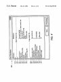
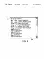
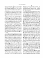
El
581/" User specified
35 X 11" Letter (portrait)
85 X 11" Letter (landscape)
11 X 14" Legal (portrait)
11 X 14" Legal (landscape)
11 X 17" Ledger (portrait)
11 X 17" Ledger (landscape)
A4 (portrait)
A4 (landscape)
A3 (portrait)
‘
A3 (landscape)
B4 (portrait)
B4 (landscape)
k
580
FIG. 8
v
U.S. Patent
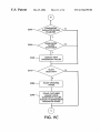
5100
May 25,2004
Sheet 9 0f 14
US 6,741,270 B1
“AD
\
STTO
IS
IMAGE SIZE
N
TAB ACTIVE?
5120
/
PERFORM OTHER
FUNCTION
5130
IS
FIT-IN BUTTON
N
ACTIVE?‘
$140
/
DISABLE DIMENSION
PARAMETER BOX AND
s15o\
5160
ENABLE FIT-IN
DIMENSION LTST BOX
DIMENSION EXPANSION
BUTTON SELECTED?
DISPLAY LIST OF
5170 \
PREDETERMINED SETS
0F DIMENSIONS
A.\\
u)
FIG. 9A
DIMENSION LIST BOX
N
U.S. Patent
May 25,2004
Sheet 10 0f 14
US 6,741,270 B1
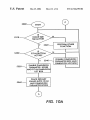
USER
SPECIFIED ENTRY
SELECTED?
SIBO
N
S2IO\
S220
ENABLE DIMENSION
PARAMETER BOXES
PLACE DEFAULT VALUES
\
INTO DIMENSION
PARAMETER BOXES
S190
OTHER
ENTRY
SELECTED?
PLACE DIMENSION
52°°\ VALUES OF SELECTED
ENTRY INTO
DIMENSION
PARAMETER BOXES
U.S. Patent
May 25,2004
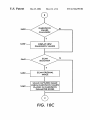
S240
Sheet 11 0f 14
DIMENSION
PARAMETER BOXES
ENABLED?
S250
S260 \
DIMENSION
VALUES
CHANGED?
DISPLAY NEW
DIMENSION VALUES
SCAN
S270
$280 \
SELECTED?
SCAN ORIGINAL
IMAGE
SCALE CAPTURED
$290 \
IMAGE USING
DIMENSION VALUES
PLACED IN DIMENSION
PARAMETER BOXES
FIG. 9C
US 6,741,270 B1
U.S. Patent
5300
May 25,2004
Sheet 12 0f 14
US 6,741,270 B1
START
_/
IS\
IMAGE sIzE
TAB ACTIVE?
$310
Y
N
5320
PERFORM OTHER
\
Is
S330
FUNCTION
N
FIT-IN BUTTON
ACTIVE?
5340
Y
DISABLE DIMENSION
\ PARAMETER BOX AND
DIMENSION LIST BOX
S350
ENABLE DIMENSION
\
PARAMETER BOXES
AND FIT-IN DIMENSION
LIST BOX
S360 \
PLACE DEFAULT
VALUES INTO FIT-IN
AND DIMENSION
PARAMETER BOXES
\A/
FIG. IOA
U.S. Patent
May 25,2004
Sheet 13 0f 14
FIT-IN
DIMENSION
EXPANSION
BUTTON
SELECTED?
$370
Y
S380
DISPLAY LIST OF
\
PREDETERMINED SETS
OF DIMENSIONS
NEW
ENTRY
SELECTED?
S400 \
PLACE NEW DIMENSION
VALUES OF SELECTED
ENTRY INTO DIMENSION
PARAMETER BOXES
$410\
CLOSED DIMENSION
LIST BOX
39
FIG. IOB
US 6,741,270 B1
U.S. Patent
May 25,2004
Sheet 14 0f 14
542°
DIMENSION
VALUES
CHANGED?
S430 \
DISPLAY NEW
DIMENSION VALUES
$440
$450
SCAN
\< SELECTED?
\
SCAN ORIGINAL
IMAGE
SCALE CAPTURED IMAGE
USING DIMENSION VALUES
PLACED IN DIMENSION
PARAMETER BOXES
/@
\)
FIG. IOC
US 6,741,270 B1
US 6,741,270 B1
1
2
SYSTEMS AND METHODS SCALING A
CAPTURED IMAGE USING
PREDETERMINED SCALE INFORMATION
dimension data into one or more text boxes of a graphical
user interface in order to inform the image capture device of
the ultimate area that the captured image Will need to be
scaled to ?t into.
BACKGROUND OF THE INVENTION
1. Field of Invention
This invention is directed to a graphical user interface for
an image capture device, such as a scanner.
10
2. Description of Related Art
Scanners and other types of image capture devices have
become ubiquitous of?ce productivity tools for generating
electronic images of physical original documents. Once an
electronic image of a physical original document has been
15
generated, the electronic image data can be used in an
in?nite variety of Ways to increase the productivity and the
product quality of an of?ce. Such image capture devices
include desktop scanners, other stand-alone scanners, digital
still cameras, digital video cameras, the scanning input
portions of digital copiers, facsimile machines and other
multi-function devices that are capable of generating elec
tronic image data from an original document, and the like.
These image capture devices can also include image data
bases that store previously captured electronic image data.
Which the captured image is to be scaled.
This invention separately provides systems, methods and
graphical user interfaces that provide an alternative method
for specifying the dimensions to Which a captured image is
to be scaled.
25
devices has dropped and the output quality of the captured
electronic image data has improved, scanners and other
image capture devices have been provided With an ever
increasing number of controllable features. Similarly, as
users have become comfortable With capturing and using
In various exemplary embodiments of the systems, meth
ods and graphical user interfaces of this invention, an image
siZe tab of a graphical user interface for an image capture
driver includes a scale portion. The scale portion, in addition
to having a number of dimension boxes that alloW the user
to directly input the desired dimensions that the captured
electronic image data obtained from original documents, the
uses to Which the electronic image data has been put, and
thus the needed control over the quality and appearance of
35
image is to be scaled to, also includes a dimension list box.
The dimension list box includes a plurality of predetermined
sets of dimensions to Which the captured image can be
scaled.
In various exemplary embodiments, the dimensions list
box includes, as the predetermined sets, one or more sets of
In response, standard interfaces betWeen such image
dimensions for common paper siZes and one or more sets of
dimensions for different paper orientations. The one or more
capture devices, including those indicated above, and the
various application programs that use such captured elec
tronic image data have been developed. These standard
predetermined sets of dimensions can also include one or
more sets of user-de?ned dimensions. These user-de?ned
dimensions alloW the user to specify the dimensions of an
interfaces alloW standard-compliant image capture devices
and standard-compliant applications to easily communicate.
image area of a document that is often used. For example, if
the user is preparing a school yearbook having a de?ned set
of dimensions to Which student photographs are to be scaled,
One exemplary embodiment of such a standard interface is
the TWAINTM interface. The TWAINTM interface alloWs any
TWAINTM-compliant application program to input and use
as Well as other commonly-used sets of dimensions to Which
electronic image data using any TWAINTM-compliant image
other types of photographs are to be scaled, each of these
commonly-used sets of dimensions can be prede?ned. Thus,
capture device.
the user does not have to continually re-enter the dimensions
for these areas by hand into the dimension boxes of the scale
SUMMARY OF THE INVENTION
The TWAINTM-compliant component protocol facilitates
portion of the graphical user interface.
These and other features and advantages of this invention
communication betWeen application programs and image
capture devices, such as those indicated above. One such
are described in or are apparent from the folloWing detailed
TWAINTM image capture device is the XEROX® Digi
description of various embodiments of the systems, methods
and graphical user interfaces according to this invention.
PathTM scanner.
The ever-increasing numbers of features provided by
images to be scaled signi?cantly reduces the user
friendliness of the graphical user interface and the produc
tivity of the user.
This invention thus provides systems, methods and
graphical user-interfaces that alloW the user to select one of
a number of predetermined sets of scale dimensions to
HoWever, as the cost of scanners and other image capture
the electronic image data, have expanded greatly.
In conventional image capture device graphical user
interfaces, the only Way to inform the image capture device
of the siZe of a region to Which the captured image Will need
to be scaled, in order to ?t the captured image into that
?xed-area region of the composite document, is via text
boxes. HoWever, When a large number of images need to be
scanned and scaled, having to continually type into the text
boxes the appropriate dimensions for each of the captured
55
image capturing devices such as the Xerox® DigiPathTM
BRIEF DESCRIPTION OF THE DRAWINGS
scanner cause users of these image capturing devices to ?nd
Various exemplary embodiments of this invention Will be
described in detail, With reference to the folloWing ?gures,
it increasingly difficult to obtain the desired scanning results.
In addition, image capture jobs are becoming longer and
Wherein:
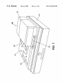
FIG. 1 is a perspective draWing of an exemplary elec
more complex.
For example, many images are captured and scaled so that
the captured image can be added into an existing electronic
document or combined With other electronic document
portions to form a composite image. In many cases, the
portion of the resulting electronic document that the cap
tured image Will be inserted into has a ?xed set of dimen
sions. In this case, the user is required to manually enter the
tronic image generating device;
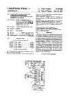
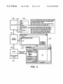
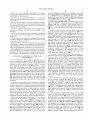
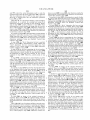
FIG. 2 is a block diagram illustrating a ?rst exemplary
embodiment of the structure of an image capture device
65
control system that incorporates the various exemplary
embodiments of the image previeWing systems, methods
and graphical user interfaces of this invention;
US 6,741,270 B1
4
3
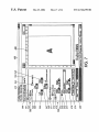
electronic image data capture devices indicated above. The
device layer 210 also includes a device interface portion 212
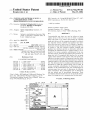
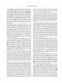
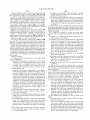
FIG. 3 is a second exemplary embodiment of an image
capturing and using system that incorporates the systems
of a TWAINTM driver, or TWAINTM data source, 250. In
and methods of this invention;
particular, as shoWn in FIG. 2, the TWAINTM driver (or data
FIG. 4 is an exemplary embodiment of a scan ticket
source) 250 bridges the device layer 210, the acquisition
layer 220 and the protocol layer 230.
illustrating various image scanning parameters according to
this invention;
The protocol layer 230 includes a TWAINTM code portion
232 of the TWAINTM driver (or data source) 250, a source
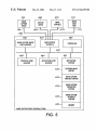
FIG. 5 is a block diagram of a second exemplary embodi
ment of the image capture control system that incorporates
the image previeWing systems, methods and graphical user
interfaces of this invention;
manager 234 and a TWAINTM code portion 236 of a
10
260.
As shoWn in FIG. 2, control and data signals are provided
from the electronic image data capture device 100 to the
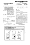
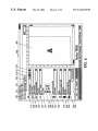
FIG. 6 is a graphical user interface incorporating the scan
previeW pane portion and visual cues according to this
invention;
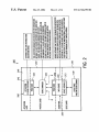
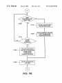
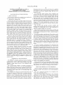
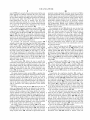
FIG. 7 shoWs in greater detail one exemplary embodiment
of the image siZe tab of the graphical user interface shoWn
in FIG. 6;
FIG. 8 shoWs one exemplary embodiment of the list box
accessible through the dimension list box portion of the
image siZe tab shoWn in FIG. 7;
15
TWAINTM driver (or data source) 250 through the device
interface portion 212 of the TWAINTM driver (or data
source) 250. Similarly, control and data signals betWeen the
TWAINTM driver (or data source) 250 and the source man
ager through the TWAINTM code portion 232 of the
TWAINTM driver (or data source) 250. The control and/or
data signals are also provided betWeen the source manager
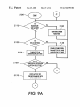
FIGS. 9A—9C are a ?oWchart outlining a ?rst exemplary
embodiment of a method for selecting a set of predetermined
234 and the application 260 through the TWAINTM code
portion 236. In various exemplary embodiments, the
TWAINTM driver (or data source) 250 controls the electronic
scale dimensions and for using the selected set of predeter
mined scale dimensions according to this invention; and
FIGS. 10A—10C are a ?oWchart outlining a second exem
TWAINTM-compliant application 260. The application layer
240 includes the application portion 242 of the application
25
plary embodiment of a method for selecting a set of prede
termined scale dimensions and for using the selected set of
image data capture device 100. In various ones of these
exemplary embodiments, the TWAINTM driver or data
source 250 is developed by the manufacturer of the elec
tronic image data capture device 100.
predetermined scale dimensions according to this invention.
The source manager 234 manages and facilitates the
interactions betWeen the application 260 and the TWAINTM
DETAILED DESCRIPTION OF EXEMPLARY
EMBODIMENTS
driver or data source 250. In various exemplary
embodiments, one or more of tWo distinct source managers
FIG. 1 illustrates a ?rst exemplary embodiment of an
electronic image data capturing device 100 usable With the
image previeWing systems, methods and graphical user
234 have been implemented. Both are compiled as dynamic
loading library modules. One exemplary dynamic load
35
interfaces of this invention. As shoWn in FIG. 1, the elec
tronic image data capture device 100 includes a control
panel 110, a document platen 120 on Which an original
document can be placed to generate corresponding elec
tronic image data and a document handler 130. In particular,
of the source manager 234 is a 32-bit program developed for
Windows@ 95/98 and Windows@ NT 4.0/5.0. In general,
these tWo dynamic load library modules are provided as part
of the TWAINTM developers tool kit and are shipped With
each TWAINTM-compliant application and at each
the document handler 130 includes a feed tray 131 on Which
the original document can be placed and a document feeder
132 Which moves each document in turn from the feed tray
131 and feeds the removed document to the document platen
120. Each document is then returned to an output tray 133
after electronic image data is generated from that original
library implementation of the source manager 234 is a 16-bit
program developed for, for example, Microsoft® Win
doWs® 3.1. The other dynamic load library implementation
TWAINTM-compliant electronic image data generating
device.
45
FIG. 3 illustrates one exemplary embodiment for access
ing the systems, methods and graphical user interfaces
document.
capture device can also be referred to as variously, a scanner,
according to this invention. As shoWn in FIG. 3, a FILE
menu 262 of a TWAINTM compliant application 260 Will
include a plurality of menu items that provide an interface to
an image capture device, an electronic image data generating
a TWAINTM compliant electronic image data capture device
device, or the like, and, regardless of the name, can be any
100, such as a TWAINTM-compliant scanner. These menu
items include various ones of at least an Acquire menu item
263, a Select Source menu item 264 or a Scan Set-Up menu
It should be appreciated that the electronic image data
one of a stand-alone scanner, a digital copier, a facsimile
machine, a multi-function device, a digital still camera, a
digital video camera, an electronic image database storing
previously generated electronic image data, or any other
knoWn or later device that is capable of generating (or
supplying) electronic image data from an original document.
FIG. 2 is a block diagram illustrating a ?rst exemplary
embodiment of the structural organiZation of an image
capture device control system 200 that incorporates the
image previeWing systems, methods and graphical user
interfaces according to this invention. As shoWn in FIG. 2,
the image capture device control system 200 includes a
device layer 210, an acquisition layer 220, a protocol layer
230, and an application layer 240. In particular, the device
layer 210 includes the image capture device 100, such as a
Xerox® DigiPathTM color scanner or any of the other
55
item 265.
As shoWn in FIG. 3, selecting the Acquire menu item 263
causes the application 260 to request that the electronic
image data capture device 100 prepare to capture electronic
image data from an original document and/or transfer cap
ture electronic image data to the image capture device
control system. In particular, in response to the selecting the
Acquire menu item 263, the application 260 can display its
oWn graphical user interface. Alternatively, the TWAINTM
driver (or data source) 250 for the selected electronic image
65
data capture device can display one of its graphical user
interfaces. Finally, if the Scan Set up menu item 265 Was
selected, the TWAINTM driver (or data source) 250 can
display a speci?c Scanner Set-Up graphical user interface.
US 6,741,270 B1
5
6
In particular, as shown in FIG. 3, When any of the menu
items 263—265 are selected, the application 260 calls the
be used. For example, the image of the original document
source manager 234. In response, the source manager
FIG. 4 or, as an 8-bit grayscale image, or as a color image
accesses each TWAINTM driver (or data source) 250 that is
present in the image capture device control system 200. The
having various color spaces and bit depths.
The resolution portion 325 indicates the resolution of the
could be captured as a binary bitmap image, as shoWn in
source manager 234 then displays, in a graphical user
generated electronic image data. The image optimiZation
interface 235, all of the different TWAINTM drivers (or data
sources) 250 present on the image capture device control
system 200. Once the user selects the particular TWAINTM
driver (or data source) 250 that the user Wishes to use, the
TWAINTM driver (or data source) 250 Will display a graphi
portion 326 indicates a particular output device, such as a
particular laser printer, a particular ink jet printer, a particu
10
cal user interface 400 that alloWs the user to select various
ones of the image capture parameters and scanning control
functions implemented in that TWAINTM driver (or data
source) 250.
captured.
15
FIG. 4 illustrates one eXemplary embodiment of a scan
ticket 300. Scan tickets contain all of the settings in the
TWAINTM graphical user interface 400, Which is discussed
than the images on the original document. Similarly, the
increase/decrease contrast parameter portion 333 indicates
or more sets of saved scan parameters, or “scan tickets” for
Whether the contrast of the electronic image data is to be
greater or less than the contrast of the images on the original
each language supported the TWAINTM driver (or data
source) 250 according to this invention. When the
TWAINTM graphical user interface 400 is displayed, only
document. The special tone adjustment parameter portion
334 is used to provide ?ner control over the tone reproduc
tion curve that is used to convert the continuous tone image
those sets of saved scan parameters, or “scan tickets” for the
25
When a set of saved scan parameters, i.e., a “scan ticket”, is
selected, all the settings contained Within that scan ticket are
used to populate the TWAINTM graphical user interface 400
according to this invention.
values of the original document to the multi-bit-depth image
values of the generated electronic image data. This is
described in greater detail in the incorporated (Attorney
Docket No. 104427) application.
The sharpen/soften parameter portion 335 used to indicate
Whether the edges Within the images in the original docu
As shoWn in FIG. 4, a scan ticket 300 includes at least a
?le name portion 310, a basic features portion 320, an image
ment should be sharpened or softened in the generated
quality portion 330 and an image siZe portion (not shoWn).
electronic image data. The background suppression param
The basic features portion 320 corresponds to the basic
features tab 500 of the TWAINTM graphical user interface
400 shoWn in FIG. 3. Similarly, the image quality portion
330 and the image siZe portion correspond to the image
quality tab 410 and the image siZe tab 550, respectively, of
The image quality pro?le parameter 331 of the image
quality portion 330 is the same as the image quality pro?le
parameter 323. The lighten/darken parameter 332 indicates
Whether the electronic image data is to be lighter or darker
in greater detail beloW. In general, there Will be a set of one
language the user is currently operating in are displayed.
lar digital copier, or the like, that Will be used to generate
hard copies of the generated electronic image data and thus
for Which the electronic image data should be optimiZed for
When the electronic image data of the original document is
35
eter portion 336 is used to indicate Whether background
suppression should be used, and if so, the color or other
quality of the background of the original document that is to
be suppressed. The negative image parameter portion 337
the graphical user interface 400 shoWn in FIG. 3. The image
quality tab 410 is described in greater detail in US. patent
application Ser. No. 09/487,271, ?led Jan. 19, 2000, and
indicates Whether the generated electronic image data should
be a negative image relative to the images on the original
document. Various other ones of the particular scanning
incorporated herein by reference in its entirety.
parameters discussed above are further disclosed in US.
As shoWn in FIG. 4, the basic features portion 320
includes a scan location parameter 321, an input original
patent application Ser. Nos. 09/487,274, 09/487,272, and
09/487,266, each ?led Jan. 19, 2000 and each incorporated
herein by reference in its entirety.
document siZe parameter 322, an original image quality
pro?le parameter 323, a mode parameter 324, a resolution
45
parameter 325, and image optimiZation parameter 326. The
image quality portion 330 includes an image quality pro?le
FIG. 5 is a block diagram illustrating a second eXemplary
embodiment of the structural organiZation of an image
captured device control system 600 that incorporates the
image previeWing systems methods and graphical user inter
parameter 331, a brightness parameter 332, an increase/
decrease parameter 333, a special tone adjustments param
eter 334, a sharpen/soften parameter 335, a background
suppression parameter 336 and a negative image parameter
faces according to this invention. As shoWn in FIG. 5, the
image capture device control system 600 includes an input/
output interface 610, a controller 620, a memory 630, an
337.
In particular, the scan location parameter 321 indicates the
application layer manager 640, a protocol layer manager
650, and an image capture device layer manager 600, each
particular electronic image capture device that is to be used
to capture electronic image data from a particular original
document. The page siZe parameter portion 322 indicates the
siZe of the input document, Whether the input document is
single-sided or double-sided, and, if the original document is
double-sided, hoW the tWo images on each side of the
original document are oriented relative to each other. The
55
interconnected by a data/control bus 690.
The image capture device 100 is connected to the input/
output interface 610 using a link 102. Similarly, an image
data sink 110 can be connected to the input/output interface
610 using a link 112. The links 102 and 112 can each be any
knoWn or later developed device or system for connecting
image quality pro?le portion 323 indicates image charac
the image capture device 100 and the image data sink 110,
respectively, to the image capture device control 600,
teristics of and enhancements to be applied to the original
document When it is made into its electronic form. Image
quality pro?les are described in greater detail in US. patent
Wide area netWork or a local area netWork, a connection over
an intranet, a connection over an eXtranet, a connection over
application Ser. No. 09/487,269, ?led Jan. 19, 2000, and
incorporated herein by reference in its entirety. The mode
portion 324 indicates the particular image capture mode to
including a direct cable connection, a connection over a
65 the Internet, or a connection over any other distributed
processing netWork or system. In general, the links 102 and
112 can each be any knoWn or later developed connection
US 6,741,270 B1
7
8
system or structure usable to respectively connect the image
application, as Well as job tickets 300, and the like. The
image capture parameters portion 634 stores a current set of
capture device 100 and the image data sink 110 to the image
capture device control system 600. It should also be appre
the image capture parameters to be used by the image
capture device 100 When capturing an image. The image
capture interface portion 635 stores the various graphical
ciated that the links 102 and 112 can be Wired or Wireless
links that use portions of the public sWitch telephone net
Work and/or portions of a cellular communication netWork.
user interfaces shoWn in FIGS. 3, 4, and 6 and as described
above and in detailed beloW.
It should also be appreciated that, in general, the image
data sink 110 can be any device that is capable of outputting
or storing electronic images generated using the image
capture device control system 600 using the systems, meth
ods and graphical user interfaces according to this invention,
such as a printer, a copier, any other image forming device,
10
The application layer manager 640 manages the applica
tion layer 240, and in particular, the application portions 242
of any executing applications 260.
The protocol layer manager 650 manages the protocol
the image capture device 100 and/or the image data sink 110,
layer 230, including the source manager 234. The protocol
layer manager 650 communications With the application
layer manager 640 using the TWAINTM application pro
gramming interfaces 236 of the executing applications 260.
The image capture device layer manager 660 manages
each of the TWAINTM drivers (or data sources) 250 that may
be implemented for different ones of the image capture
devices 100 that may be accessible by the image capture
such as, for example, in a digital copier. With such a
device control system 600 over various ones of the links
con?guration, for example, the image capture device 100,
the image data sink 110 and the image capture device control
102. In particular, the image capture device layer manager
660 communicates With the protocol layer manager 650
system 600 may be contained Within a single device.
using the acquisition layer application programming inter
The input device or devices 670 can include any one or
25
more of a mouse, a keyboard, a touch pad, a track ball, a
touch screen, or the like, or any other knoWn or later
face 232 of the particular TWAINTM driver (or data source)
250. Similarly, the image capture device layer manager 660
communicates With the image capture device 100 through
developed device that is capable of inputting data and
the input/output interface 610 and over the link 102 using the
device interface portion 212.
The image capture device layer manager 660 causes
various ones of the image capture graphical user interfaces,
a facsimile device, a display device, a storage device, or the
like.
While FIG. 5 shoWs the image capture device 100, the
image capture device control system 600 and the image data
sink 110 as separate devices, the image capture device
15
control system 600 may be integrated With either or both of
control signals over the link 672 to the input/output interface
610. Similarly, the display device 680 can be any knoWn or
later developed display device, including a cathode ray tube
type monitor, a ?at screen type monitor, an LCD monitor, or
any other knoWn or later developed device on Which the
graphical user interfaces according to this invention can be
displayed and interacted With using one or more of the input
such as the graphical user interface 400 shoWn in FIG. 3, to
be displayed on the display device 680. The user can then
change and/or input the various image capture parameters.
The various image capture parameters can be input through
the various graphical user interfaces that the image capture
device layer manager 660 displays on the display device
devices 670. The display device 680 is provided With control
and/or data signals from the input/output interface 610 over
the link 682.
Like the signal lines 102 and 112, the links 672 and 682
680. Then, after the user saves the various image capture
parameters or initiates the corresponding image capture
device, the image capture device layer manager 660 stores
the selected image capture parameters in the image capture
can be any knoWn or later developed device or system for
connecting the input devices 670 and the display device 680,
respectively, to the image capture device control system 600,
parameters portion 640. The image capture device layer
manager 660 then outputs the selected image capture param
including a direct cable connection, a connection over a
eters through the input/output interface 610 and over the link
Wide area netWork or local area netWork, a connection over
a intranet, a connection over an extranet, a connection over 45 102 to the image capture device 100. The image capture
device 100 then uses the various image capture parameters
received from the image capture device control system 600
When capturing electronic image data from an original
the Internet, a connection over the public sWitched telephone
netWork, a connection over a cellular netWork, or a connec
tion over any other distributed processing or communica
tions netWork or system, including both or either Wired and
document and When supplying that capture electronic image
Wireless systems. In general, the links 672 and 682 can each
be any knoWn or later developed connection system or
structure usable to connect the input devices 670 and the
system 600.
FIG. 6 shoWs one exemplary embodiment of the graphical
display device 680, respectively, to the image capture device
user interface 400. As shoWn in FIG. 6, the graphical user
control system 600.
The memory 630 includes an application portion 631 in
Which an application program and any application ?les used
by that application program can be stored. Similarly, the
captured image buffer 632 is used to store the captured
image data input from the image capture device 110 over the
signal line 102 and through the input/output interface 610. In
general, the captured electronic image data Will be stored in
the captured image buffer 632 under control of the controller
620 the image capture device layer manager 660, the pro
tocol layer manager 650 and/or the application layer man
ager 640.
The image capture pro?les portion 633 stores the image
capture pro?les, as set forth in the incorporated 269
data over the link 110 to the image capture device control
55
interface 400 includes the image quality tab 410 and the
image siZe tab 550 in addition to the basic features tab 500.
The basic features tab 500 includes a scan ticket portion 510,
an original document parameters portion 520, and an image
capture parameters portion 540. The basic features tab 500
also includes an instance of a “HoW Do I” button 430. The
“HoW Do I” button 430 is usable to access an operating
instructions help function, Which is disclosed in greater
detail in the incorporated 266 application.
In particular, the scan ticket portion 510 includes a status
icon 512 that indicates the saved status of the scan ticket
65 indicated in a scan ticket selection box 514. The current
image capture parameters input into each of the basic
features tab 500, the image quality tab 410 and the image
US 6,741,270 B1
10
particular modes displayed When the mode list boX 542 is
selected Will depend on the particular image capture device
size tab 550 can be saved to the scan ticket named in the scan
ticket dialogue boX 514 by selecting the save scan ticket
button 516. In contrast, the named scan ticket displayed in
the scan ticket dialogue boX 514 can be deleted by selecting
identi?ed in the scan location list boX 522 and the particular
modes available With that particular image capture device.
the delete scan ticket button 517. The shoW scan ticket
The possible modes, include, but are not limited to, 1-bit or
button 518 alloWs the user to quickly vieW all of the
currently loaded scan settings in a teXt list. This alloWs the
user to vieW the information on every setting Without having
black/White captured images, 8-bit or grayscale captured
to navigate all of the various dialogues in the various
portions of the graphical user interface 400.
The original document parameters portion 520 of the
images, or various types of 24-bit captured images, includ
ing red/green/blue (RGB) color, standard red/green/blue
(sRGB) color and Luminance/Blue Chromaticity/Red Chro
10
maticity (YCbCr) color.
15
output resolution of the captured image, in dots per inch
(dpi). The optimiZe image list boX 546 alloWs the user to
select the output device for Which the various captured
image quality parameters on the image quality tab 410
The resolution list boX 544 alloWs the user to select the
basic features tab 500 includes a scan location list boX 522,
a page siZe list boX 524, a double-sided check boX 526, and
an image quality pro?le list boX 528. The original document
portion 520 also includes a document orientation portion
530 that alloWs the user to specify hoW the document Will be
oriented on the platen 120 of the image capture device 100.
The document orientation portion 530 is described in greater
should be set to so that the captured image, When printed on
the selected output device, Will provide the highest quality
output image. In particular, in one eXemplary embodiment,
detail in the incorporated 272 application.
In particular, the document orientation portion 530
includes a short edge ?rst/long edge ?rst (SEF/LEF) toggle
When a printer is selected in the optimiZe image list boX 546,
the tone reproduction curve (TRC) for the 1-bit (black/
White) mode is selected as the tone reproduction curve for
button 532, a rotate button 534 and an input document
the indicated printer.
mimic portion 536. The SEF/LEF toggle button 532 alloWs
FIG. 7 shoWs the image siZe tab 550 in greater detail. As
shoWn in FIG. 7, the image siZe tab 550 includes a reset
values button 551, a crop/frame portion 560 and a reduced/
enlarge portion 570. When the reset values button 551 is
the user to indicate Whether the ?rst edge of the original
document to be introduced into the document handler 130 of
25
the image capture device 100 is the long edge, i.e., the 11
pressed, the various image capture parameters set forth in
inch edge of standard 81/z><11 inch paper, or the short edge,
i.e., 81/2 edge of standard 81/z><11 inch paper. In particular, the
user Will be eXpected to feed the original document into the
document handler 130 or place it on the platen 110 in the
same orientation as speci?ed in the graphic displayed on the
the crop/frame portion 560 and the reduce/enlarge portion
570 are reset to the selected default values. Additionally, the
image siZe tab 550 like the basic features tab 500, the image
siZe tab 550 also includes an instance of the “HoW Do I”
button 430.
SEF/LEF toggle button.
The rotate button 534 alloWs the user to specify the
The crop/frame portion 560 of the image siZe tab 550
orientation of the image on the input document. That is, the
user may be providing the original document to the docu
ment handler using the long edge ?rst orientation While the
image has been placed onto that original document in a
landscape orientation. In this case, by activating the rotate
includes a crop/frame checkboX 561, a crop radio button
562, a frame radio button 563, a mirror checkboX 564, and
35
a set of top, left, right, and bottom parameter entry boXes
564—568 that de?ne the location of the rectangle to be
cropped out of the capture electronic image data. Finally, the
crop/frame portion 560 includes an all values equal check
button 534, the image orientation of the captured image Will
be rotated 90° clockWise.
The input document mimic portion 530 is a graphic that
assists the operator in putting the document into the scanner
boX 569.
In particular, the crop/frame checkboX 561 enables or
disables all of the crop/frame feature parameters. When
checked, the crop/frame checkboX 561 enables all of the
correctly to receive the desired output. That is, the input
document mimic portion 536 can be used by the user to
45
precisely identify to the image capture device the paper siZe
the crop/frame checkboX 561 generates a crop/frame mar
quee selection control 484 in a previeW portion 480 of the
graphical user interface 400. The crop/frame marquee selec
tion control 484 is discussed in greater detail beloW. The
crop/frame checkboX 561 also alloWs the user to easily turn
and feed direction of the original document to be scanned as
Well as the image orientation, so that the captured images
Will be returned to the calling application in the desired
orientation.
The image quality pro?le list boX 528 alloWs the user to
select an image quality pro?le. As indicated in the incorpo
rated 269 application, each image quality pro?le is a col
lection of all the settings on the image quality tab and the
various dialogue boXes and other graphical user interface
Widgets that are accessed through the image quality tab. In
on or off the selected crop values on a scan-by-scan basis,
Without having to reset or clear the values entered into each
of the crop/frame control portions 562—569.
The top, left, right and bottom parameter boXes 565—568
55 alloW the user to de?ne a rectangular selection area of the
original document that Will be cropped or framed. The top,
left, right and bottom parameter boXes 565—568 alloW the
particular, the image quality pro?le list boX 528 Will include
user to specify the distances betWeen the corresponding
margin of the original document, based on the siZe of the
original document selected in the page siZe teXt boX 524, and
the corresponding edge of the rectangular selection area. The
“all values are equal” check boX 569, When checked, locks
the same image quality pro?les as Will be provided on the
image quality tab. When an image quality pro?le is selected
using the image quality pro?le list boX 528, the image
quality pro?le parameters displayed in the various portions
of the image quality tab Will be change accordingly.
The image capture parameters portion 540 of the basic
feature tab 500 includes a mode list boX 542, a resolution list
boX 544, and an optimiZe image list boX 546. The mode list
boX 542 alloWs the user to select the output mode of the
image capture device 100. It should be appreciated that the
crop/frame controls 562—569. Additionally, When checked,
65
all four of the parameters 565—568 together.
The crop radio button 562, When selected, indicates that
the portions of the scanned electronic image data outside of
the rectangular selection area de?ned by the values in the
dimension boXes 565—568 should be deleted. Thus, the


![[l] STORAGE](http://vs1.manualzilla.com/store/data/005949981_1-aa131963b29a7cfe7d43fe9de2ac578c-150x150.png)