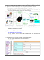
1
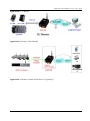
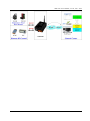
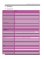
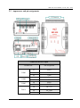
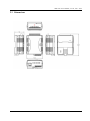
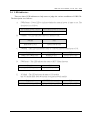
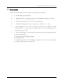
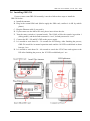
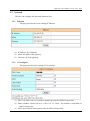
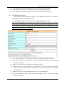
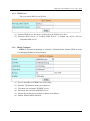
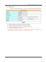
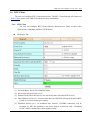
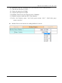
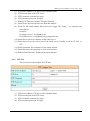
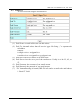
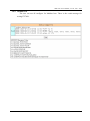
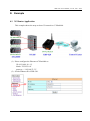
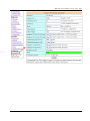
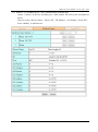
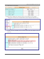
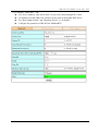
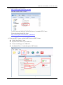
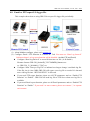
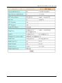
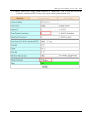
GRP-520 User Manual, V1.20, Aug. 2014 GRP-520 Series 3G Gateway User Manual v1.20 High Quality, Industrial Data Acquisition, and Control Products 1 GRP-520 User Manual, V1.20, Feb. 2014 Warranty All products manufactured by ICP DAS are warranted against defective materials for a period of one year from the date of delivery to the original purchaser. Warning ICP DAS assumes no liability for damages consequent to the use of this product. ICP DAS reserves the right to change this manual at any time without notice. The information furnished by ICP DAS is believed to be accurate and reliable. However, no responsibility is assumed by ICP DAS for its use, or for any infringements of patents or other rights of third parties resulting from its use. This is licensed under the terms of the GNU General Public License version 2. Copyright Copyright 2012 by ICP DAS CO., LTD. All rights reserved worldwide. Trademark The names used for identification only may be registered trademarks of their respective companies. Version Date Author Description 1.00 2013/03/20 Malo Release version 1.10 2014/02/05 Malo Add new feature 1.20 2014/08/05 Malo Add new feature: RTU Client 2 GRP-520 User Manual, V1.20, Aug. 2014 Table of Contents 1. Introduction ............................................................................................... 4 1.1 1.2 Features ............................................................................................................. 5 Applications ...................................................................................................... 5 2. Hardware ................................................................................................... 8 2.1 Specifications ................................................................................................... 8 2.2 2.3 2.4 2.5 Appearance and pin assignments ...................................................................... 9 Dimensions ..................................................................................................... 10 LED indicators ................................................................................................ 11 Rotary Switch .................................................................................................. 12 2.6 Installing GRP-520 ......................................................................................... 13 3. Web Utility .............................................................................................. 14 3.1 3.2 3.3 Login the Utility ............................................................................................. 14 Information ..................................................................................................... 15 Network .......................................................................................................... 18 3.4 3.5 3.6 System ............................................................................................................ 25 VxServer ......................................................................................................... 29 RTU Client...................................................................................................... 31 4. Example ................................................................................................... 38 4.1 4.2 4.3 4.4 3G Router Application .................................................................................... 38 Web Server and IP Camera Application ......................................................... 41 Remote I/O Control / Temperature Monitor ................................................... 46 Modbus/TCP to Modbus/RTU over 3G, and Card Reader Monitor ............... 51 4.5 4.6 4.7 4.8 RTU Client for Remote Control Application with RTU API.......................... 56 RTU Client for Remote Control Application with OPC DA Server. .............. 68 RTU Client for Remote Control Application with InduSoft........................... 71 Email or FTP report I/O logger file. ............................................................... 73 3 GRP-520 User Manual, V1.20, Aug. 2014 1. Introduction The GRP-520 provided by ICP DAS is a 3G gateway for Ethernet or serial port. With optional GPS model, the GRP-520 can also be a GPS tracking system. It can be used in M2M application fields to transfer the remote I/O, Modbus data or video of the camera via 3G/2G. Within the high performance CPU, the GRP-520 series can handle a large of data and are suit for the hard industrial environment. The GRP-520 series have 3G module, Ethernet interface, and optional GPS module. 4 GRP-520 User Manual, V1.20, Feb. 2014 1.1 Features Support Tri-band WCDMA 2100/1900/850 MHz and Quad-band GSM 850 / 900 / 1800 / 1900 MHz. 10/100 Base-TX compatible ethernet eontroller COM port: COM1 (3-wire RS232), COM2 (RS-485), COM3 (3-wire RS232) GPS : 32 channels with All-In-View tracking (option) Support Micro SD card. Provide 3G Router function. Support port mapping (port forward) function. Serial Port to 3G Gateway High reliability in harsh environments DIN-Rail mountable 1.2 Applications Signal Alarm Report System 3G Router Home/Factory security Remote Video Monitor Energy Management Temperature Monitoring 5 GRP-520 User Manual, V1.20, Feb. 2014 Application 1: 3G Router Application 2: Remote Video Monitor Application 3: Remote Control (Serial Port to 3G gateway) 6 GRP-520 User Manual, V1.20, Feb. 2014 7 GRP-520 User Manual, V1.20, Feb. 2014 2. Hardware 2.1 Specifications Item System / Software GRP-520 3G Gateway Ethernet and Serial port (1x RS-232, 1x RS-485) to 3G Embedded service Web Server, 3G router System CPU SRAM Flash EEPROM Expansion Flash Memory Expansion Disk RTC(Real Time Clock) 64-bit Hardware Serial Number Watchdog Timer LED Indicator Rotary Switch ARM CPU (312MHz) 64 MB 64 MB 16 KB (Data Retention: 40 years; 1,000,000 erase/write cycles) SD Card (Max. 32GB SDHC) USB disk (format : FAT32) Provide seconds, minutes, hours, day of week/month, month and year Yes Yes 3 LEDs (SYS/PWR, F.W., 3G) Yes (0~9) GSM System Frequency Band GPRS connectivity DATA GPRS GSM : 850/900/1800/1900 MHz GPRS class 12/10; GPRS station class B Downlink transfer: Max. 85.6 kbps; Uplink transfer: Max 42.8kbps 3G System Frequency Band Data Transmission WCDMA 2100/1900/850 MHz WCDMA / HSDPA / HSUPA Downlink transfer: Max. 7.2Mbps; Uplink transfer: Max 5.76Mbps GPS System (option) Support Channels Protocol Support 32 NMEA 0183 version 3.01 Comm. Interface Ethernet COM1 COM2 COM3 RJ-45, 10/100 Base-TX (Auto-negotiating, Auto MDI/MDI-X, LED indicators) RS-232 (RxD, TxD and GND); Non-isolated(Console, Debug) RS-485 (D2+, D2-); 3000 VDC isolated RS-232 (RxD, TxD and GND); Non-isolated Mechanism Casing Plastic Dimensions(W x L x H) 91 mm x 132 mm x 52 mm (W x L x H) Installation DIN-Rail Power Protection Frame Ground Protection Required Supply Voltage Power Consumption Power reverse polarity protection ESD, Surge, EFT, Hi-Pot +10 VDC ~ +30 VDC 4.8W ( 200 mA @ 24 VDC) Environment Operation Temp. Storage Temp. Humidity -25℃ to 75℃ -30℃ to 80℃ 5~95% non-condensing 8 GRP-520 User Manual, V1.20, Feb. 2014 2.2 Appearance and pin assignments COM Port & Power Input Terminal No. COM1 COM2 COM3 Power Pin Assignment 01 RxD1 02 TxD1 03 GND 04 D+ 05 D- 06 RxD3 07 TxD3 08 DC.+VS 09 DC.GND 10 F.G. 9 GRP-520 User Manual, V1.20, Feb. 2014 2.3 Dimensions 10 GRP-520 User Manual, V1.20, Feb. 2014 2.4 LED indicators There are three LED indicators to help users to judge the various conditions of GRP-520. The description is as follows: A. B. C. PWR(Green):Power LED to indicate whether the external power is input or not. The description is as follows: The external power is active The external power is not active on off OS(Red):OS LED indicates if the OS is normal or fail. Normal Fail Heart beat (1 sec.) Always ON or OFF FW(Red):This LED indicates the status of VxServer firmware (Serial port to 3G). Connected 500ms ON / 500ms OFF D. Fail Always ON or OFF FW(Green):This LED indicates the status of RTU Client firmware. Normal 500ms ON / 500ms OFF E. Connecting Blanking(4 sec) Fail Always ON or OFF 3G (Red):The LED indicates the status of 3G module. (the 3G module need about 60 seconds to register network usually) Registered 800ms ON / 800ms OFF 3G/GPRS data transmit 200ms ON, 200ms OFF 11 Fail Always ON or OFF GRP-520 User Manual, V1.20, Feb. 2014 2.5 Rotary Switch There are some functions of rotary switch. The description is as follows: A. 0:Normal mode, default position. B. 1 : Debug mode, this a engineering mode, we can communicate with the OS console. C. 2 : OS Update with MicroSD card. 2G SD card is supported. D. 4 : OS Update with Ethernet. It is used in the factory. Please don’t use it. E. 8 : Factory default IP. If you set as 8, and then reset the device, its Ethernet IP will be “192.168.255.1”. if you forgot your device IP, you can use this function to re-configure your device IP. F. 9 : Factory default setting. If you forgot your password, you can follow the steps below: (1) set rotary switch as 9 (2) and connect TxD3 and RxD3 together (3) reset your device (4) if the Red and Green FW Led blinking, it means restore as factory default setting successfully. Please turn rotary switch as 0. 12 GRP-520 User Manual, V1.20, Feb. 2014 2.6 Installing GRP-520 If users want to start GRP-520 normally, it needs to follow these steps to install the GRP-520 below: A. Install the antenna B. Plug in the normal SIM card (Before apply the SIM card, confirm it is OK by mobile phone.) C. Plug the Ethernet cable if you need it. D. If you want to use the Micro SD card, please insert it into the slot. E. Turn the rotary switch to 0 (normal mode). The COM1 will be the console in position 1 (debug mode), and the default username is “root”, default password is “root”. F. Connect the DC.+VS and DC.GND to the power supply. G. It is needed to wait about 20 ~ 30 seconds for OS booting. After finishing the process, GRP-520 would be in normal operation mode and the OS LED would blank as heart beat per 1 sec. H. It is needed to wait about 30 ~ 60 seconds to search the 3G/2G base and register to the ISP. After finishing the process, the 3G LED would blank per 1 sec. 13 GRP-520 User Manual, V1.20, Feb. 2014 3. Web Utility You must configure GRP-520 from web utility before using. 3.1 Login the Utility Please login before you use the web utility. The default username is “admin”, and the default password is “admin” Default IP = “192.168.255.1” Default Mask = “255.255.0.0” Default Gateway = “192.168.0.1” After login, the screenshot is showed as below: 14 GRP-520 User Manual, V1.20, Feb. 2014 3.2 Information You can get the basic information of the device here. 3.2.1 Device Information This page provides basic device information: (1) Product Name: the Name of your product (2) Serial Number: only one number of ICPDAS product (3) OS Kernel Version: linux kernel version. 15 GRP-520 User Manual, V1.20, Feb. 2014 3.2.2 Network Information This page provides basic network information: (1) Ethernet: Ethernet information .Mode: static IP or DHCP .MAC address: a unique identifier assigned to network interfaces. .IP Address: a computer's address under the Internet Protocol .Mask: Mask will be provided from Gateway provider. (2) 3G/GPRS Network information: the information will show out after dial up .Status: “connected” mean the modem dial-up success. .IP Address: the IP is provide by ISP provider. .P-t-P: provide by ISP provider .Mask: provide by ISP provider (3) Modem information: .PIN Code: the status of PIN Code. Please refer to below: READY: PIN Code is ready. SIM PIN: need PIN code of SIM card SIM PUK: need PUK code of SIM card SIM failure: Access SIM Card failure 16 GRP-520 User Manual, V1.20, Feb. 2014 .Register Status: Indicating GRP-520 connect to 3G base successful or not. .Signal Quality: the 3G signal quality. 3.2.3 Storage Information This page provides information about “Micro SD card”, “USB Disk”: (1) USB Disk / SD card: .Size: total size of storage .used: the size is used .Available: free space in the storage .Path: the mount point in file system. 17 GRP-520 User Manual, V1.20, Feb. 2014 3.3 Network The user can configure the Network functions here. 3.3.1 Ethernet This page provides the basic settings of Ethernet: (1) IP Address: IP of Ethernet. (2) Mask: the Mask of the gateway. (3) Gateway: IP of the gateway. 3.3.2 3G Configure This page provides basic settings of 3G network: (1) PIN Code: PIN Code are 4 character number provided by SIM Card provider (2) Phone Number: usually fill it as “*99***1#” or “*99#”. The number is depended on SIM Card provider (3) APN: Access Point Name, please ask your SIM Card provider. 18 GRP-520 User Manual, V1.20, Feb. 2014 (4) User Name: the username for dial-up. Please ask your SIM Card provider. (5) Password: the password for dial-up. Please ask your SIM Card provider. (6) Auto-Dialing: Enable this function to dial-up to 3G network after power on. 3.3.3 3G/GPRS Reconnection This function can keep the device always on 3G/GPRS network, but it will send the IMCP signals to check 3G/GPRS network. The default setting is “Disable” to prevent it from using extra packets. PS. Some ISP upgrades their system cause GRP-520 difficult to dial-up in Taiwan. Please enable this function to avoid this problem. When GRP-520 dial-up fails, it will try to solve this problem automatically. (It maybe take about 10 minutes, and this problem was solved in v1.1.1 and later). (1) Server IP: the target IP or URL that you want to send signal (ping the target IP). (2) Max. Retry: if the system retry time is over this number, it will reset 3G modem and dial-up to try again. (3) Interval Time: the interval time between this retry and last. (4) Timeout: the device will connect to 3G network for a period of 50 second (default value) after resetting the Modem, and then the system will start check the connection of 3G network. (5) Enable Function: if you enable this function, it will run immediately. (6) Alive: the firmware status. “true”(color green) means “alive”. “false”(color gray) means “not alive”.. 19 GRP-520 User Manual, V1.20, Feb. 2014 3.3.4 DNS Server The user can set DNS server IP here: (1) Primary DNS Server: the device will use it to get DNS service first. (2) Alternate DNS Server: if “Primary DNS Server” is invalid, the device will use “Alternate DNS Server”. 3.3.5 (1) (2) (3) (4) (5) (6) DDNS Configure DDNS is a method of updating, in real time, a Domain Name System (DNS) to point to a changing IP address on the Internet: Server: the address of DDNS service provider. Domain: The domains name you registered. Username: the username of DDNS service. Password: the password of DDNS service. Period: the period time (seconds) to update your address. Enable: Enable DDNS function. 20 GRP-520 User Manual, V1.20, Feb. 2014 3.3.6 DHCP Server The Device could be a DHCP Server. The user can set the IP range for DHCP client. (1) Subnet, Netmask, Lease-time: these items are read-only. (2) Routers: the router IP. It usually is set as your device IP. (3) Range: the IP range that DHCP server assign to DHCP client. (4) Enable: Enable DHCP Server service. * If your device need link to Internet via 3G/GPRS, please enable the “Routing rule” for “DHCP Range” here. About “routing rule”, please refer next section. 21 GRP-520 User Manual, V1.20, Feb. 2014 3.3.7 Routing This page provides routing rule configuration. (1) IP: IP address. (2) Mask: the mask will effect how many IP this rule manages. ”24” = 255 IPs, “28” = 16 IPs, “32” = 1 IPs. (3) Target: the target interface of the rule. For example: The Rule 0: This rule will push the socket packages from the address 192.168.27.0 ~ 192.168.27.255 forward to “ppp0” (3G network). The Rule 1: This rule will push the socket packages from the address 192.168.0.0 ~ 192.168.0.15 forward to “ppp0” (3G network). 22 GRP-520 User Manual, V1.20, Feb. 2014 3.3.8 Port Mapping (Port Forward) This page provides Port Mapping rule configuration. (1) Type: the protocol type. There are “TCP” and “UDP” (2) From: the interface that the socket comes from. ”ppp0” is 3G interface. (3) Port: the port that the socket comes from. (4) Target IP: the IP that the socket goes forward. (5) Target Port: the Port of the “Target IP”. For example: The Rule 0: This rule will bind the socket from the “ppp0” and Port=”10080” with 192.168.0.10:80. The Rule 1: This rule will bind the socket from the “ppp0” and Port=”10021” with 192.168.0.10:21. 23 GRP-520 User Manual, V1.20, Feb. 2014 3.3.9 Diagnostic This page provides the tools to check the problem of the network. (1) Ping Test: this tool will ping “Target IP”, and show result below. (2) Traceroute: this tool will trace routing path to “Target IP”, and show the result below. (3) Route Information:: this tool will show route setting below. 24 GRP-520 User Manual, V1.20, Feb. 2014 3.4 System The user can configure “password”, “system parameter”, reboot the device and restore factory settings here. 3.4.1 Password The user can change the password of the web utility here. (1) Password: new password. (2) Confirm: confirm the password again. 3.4.2 Reboot The user can reboot the device here. 25 GRP-520 User Manual, V1.20, Feb. 2014 3.4.3 Reboot Timer The user can use this function to reboot system automatically. (1) Interval Time: Interval Time to reboot system. (2) Enable: Enable Reboot Timer function. 3.4.4 Backup & Restore The user can backup the device settings and restore it here. (1) Backup: Press “Backup” button to backup settings into your PC. (2) Restore: Press “Browse” button to select file, and then press “Restore” button to store your settings. 3.4.5 Restore Factory The user can restore the device setting to factory default. 26 GRP-520 User Manual, V1.20, Feb. 2014 3.4.6 System Time This page provide information about the time of the device.: (1) Set Time: set the time of GRP-520 the same as your computer. (2) NTP Server: device will connect to the NTP Server to synchronize time. (3) Timezone: if you do not know your timezone, please click the link “check timezone” to find out. (4) Enable NTP Function: if you enable it, GRP-520 will update time automatically. 3.4.7 System Service This page indicates the status of system services. (1) Process Name: .pppd: this process will dial-up to 3G network. .dhcpd: DHCP Server. .ddns: ddns client process. It will auto update IP. (2) Alive: the process status. “true”(color green) means “alive”. “false”(color gray) means “not alive”. 27 GRP-520 User Manual, V1.20, Feb. 2014 (3) Start: click the button to start this process. (4) Stop: click the button to stop this process. 28 GRP-520 User Manual, V1.20, Feb. 2014 3.5 VxServer The user can configure VxServer firmware here. 3.5.1 VxServer The user can configure VxServer firmware here. (1) Server IP: Server IP or URL. (2) Server Port: the port of the server. (3) Heartbeat Time: if setting this value small, it is sensitive to detect network disconnected. (4) Device ID: ID of the device. If you set it as “1”, you will find that “visual IP” is “192.168.20.1” on the server side. (5) Alias: an alias of device. Max. length is 8 characters. 29 GRP-520 User Manual, V1.20, Feb. 2014 (6) Time Interval: if the Time Interval between the two serial port data is more than this value, the data will be sliced into two network packet. And if there is no enough time interval, but data length is over 1000 bytes (default value), the data still be sliced into two network packet. (7) Data Length: if serial port data length is over this value, the data will be sliced into two packets. Usually you just set this value as 1000 if you don’t need this function. (this value is limited by network protocol) (8) Modbus TCP to RTU: Modbus/TCP to Modbus/RTU gateway function. Port1 is COM2 of GRP-520 (RS-485); Port2 is COM3 of GRP-520 (RS-232). (9) Default Baudrate: this value is dependent on your Modbus RTU device. Please set this value is the same as your Modbus RTU device. (10) Default Format: configuration of “Data bits”, “Parity” and “Stop bit”. 8, 7 mean 8 or 7bits of Data bits N, O, E mean None, Odd, Even of Parity 1, 2 mean 1 or 2 bits of Stop bit (11) Enable Function: Enable the firmware immediately. (12) Alive: the firmware status. “true”(color green) means “alive”. “false”(color gray) means “not alive”. 30 GRP-520 User Manual, V1.20, Feb. 2014 3.6 RTU Client The user can configure RTU Client function here. The RTU Client function will connect to RTU Center, please refer GRP-520 website for more information. 3.6.1 (1) (2) (3) (4) RTU Client The user can configure RTU Client firmware function here. There are three tabs: (1)Main Info. (2)Modbus Number (3)FTP/Email Main Info. Tab: Server Address: Server IP or Domain Name. Server Port: the port of the server. Station ID: the ID for this device. (do not be the same with other RTU device) Data Update Period (sec.): set report time interval. GRP-520 will report all data to RTU Center every interval time your setting. (5) Heartbeat Period (sec.): set heartbeat time interval. 3G/GPRS connection will be terminate by ISP, this parameter can detect broken connection early. “Heartbeat Period” must be smaller than “Data Update Period”. 31 GRP-520 User Manual, V1.20, Feb. 2014 (6) (7) (8) (9) (10) (11) (12) Baud Rate (RS-485 for Modbus/RTU): the baud rate of the COM2 (RS-485). Data bit: the data bit of COM2. Parity: the parity bit of COM2. Stop bit: the stop bit of COM2. Modbus Timeout (ms): the Timeout value of Modbus. Enable Function: enable the RTU Client function. Alive: the firmware status. “true”(color green) means “alive”. “false”(color gray) means “not alive”. Modbus Device: the interface for adding Modbus I/O device. 32 GRP-520 User Manual, V1.20, Feb. 2014 (1) Modbus Device Number: display the modbus device number here. You can choose a model in the list, and then use the “Add” button to add a new modbus device. (2) Device Name: the Name of the modbus device. This Name will be showed in RTU Center. (3) Device ID: the modbus ID. (4) IP: the IP of modbus/TCP device. Keep it empty for Modbus/RTU device. (5) Port: the Port number of modbus/TCP device. (6) DI Number: the number of DI channel. (7) DO Number: the number of DO channel. (8) AI number: the number of AI channel. (9) AO number: the number of AO channel. (10) (11) (12) (13) DI Address: the start address for reading DI value. DO Address: the start address for reading DO value. AI Address: the start address for reading AI value. AO Address: the start address for reading AO value. 33 GRP-520 User Manual, V1.20, Feb. 2014 FTP / Email: this function will send back all I/O data log file automatically. The period time to send is depending on “Max. Time per Log File (hour)” parameter. (1) Data Log Interval (sec.): the time interval to record I/O data to logger file. Set as “0” to disable all function in this tab. (2) Max. Time per Log File (hour): the time interval to change log file and send log file via Email or FTP. GRP-520 will change logger file before the file be over 3 MB, and move old logger file into “LOGFILE” folder, and send out the file at the same time. If you enable FTP or Email function, GRP-520 will copy old logger file into “FTP_UPLOAD” and “MAIL_UPLOAD” for sending out files. If send FTP or Email logger file fails, GRP-520 will send files next time. 34 GRP-520 User Manual, V1.20, Feb. 2014 (3) (4) (5) (6) (7) (8) (9) FTP Server Address: FTP Server IP or Domain Name. FTP Port: the port of the FTP server. FTP Username: username for login FTP password: password for login Enable FTP Function: enable FTP report function. Email From: the email will be sent from this address. Email To: the email address that will receive logger file. Using “,” to separate each mail address Example: for single receiver: [email protected] for multi-receiver: [email protected],[email protected] (10) Email Server: the server address of the email server. (11) Email Server Port: the server port of the email server. Usually it will be 25, 465, or 587. (12) Email Username: the username of your email account. (13) Email Password: the password of your email account. (14) Enable Email Function: Enable email report function. 3.6.2 FTP Test The user can test all configure for FTP here. (1) FTP Server Address: FTP Server IP or Domain Name. (2) FTP Port: the port of the FTP server. (3) FTP Username: username for login (4) FTP password: password for login 35 GRP-520 User Manual, V1.20, Feb. 2014 3.6.3 Email Test The user can test all configure for Email here. (1) Email From: the email will be sent from this address. (2) Email To: the email address that will receive logger file. Using “,” to separate each (3) (4) (5) (6) mail address Example: for single receiver: [email protected] for multi-receiver: [email protected],[email protected] Email Server: the server address of the email server. Email Server Port: the server port of the email server. Usually it will be 25, 465, or 587. Email Username: the username of your email account. Email Password: the password of your email account. (7) “Test” button: Pressing this button, GRP-520 will send a test mail to the mail address in “Email To” field. 36 GRP-520 User Manual, V1.20, Feb. 2014 3.6.4 Modbus Test The user can test all configure for Modbus here. There is the result message for testing ET-7026. 37 GRP-520 User Manual, V1.20, Feb. 2014 4. Example 4.1 3G Router Application This example shows the steps to share 3G network to 3 XPac8000. (1) Please configure the Ethernet of XPac8000 as: IP=192.168.0.10 ~ 12 Mask=”255.255.0.0” gateway = “192.168.27.51”. (2) Set the Ethernet IP of GRP-520. 38 GRP-520 User Manual, V1.20, Feb. 2014 (3) Set Pin code of your SIM card, and Enable “Auto-Dialing” function. Set “User Name” and “Password” if your SIM card need it. Press “Modify” to save (4) Enable “3G/GPRS Reconnection” function to keep your 3G/GPRS network always online (usually, ISP will disconnect your connection once every 1~3 days). Generally, you can set the Server IP as your server’s IP or google’s DNS server IP (8.8.8.8). If you use MDVPN, please set the Server IP as your Server IP that doesn’t deny ICMP service (Ping). Press “Modify” after you finish all settings. 39 GRP-520 User Manual, V1.20, Feb. 2014 (5) Set routing rule to share 3G network. This setting will share 3G network to IP address from 192.168.0.0~192.168.0.255. Press “Modify” (6) Please reboot GRP-520 to enable settings. (you can reboot from the web or the power source) 40 GRP-520 User Manual, V1.20, Feb. 2014 4.2 Web Server and IP Camera Application This example shows the steps to share 3G network to ET-7044 and IP camera. (1) Please Set the Ethernet of ET-7044 and IP camera as: IP=192.168.0.20 ~ 22 Mask=”255.255.0.0” gateway = “192.168.27.51” (2) Set the IP of GRP-520 as below: IP=”192.168.27.51” Mask=”255.255.0.0” 41 GRP-520 User Manual, V1.20, Feb. 2014 (3) Set Pin code of your SIM card, and Enable “Auto-Dialing” function. Set “User Name” and “Password” if your SIM card need it. Press “Modify” (4) Enable “3G/GPRS Reconnection” function to keep your 3G/GPRS network always online (usually, ISP will disconnect your connection once every 1~3 days). Generally, you can set the Server IP as your server’s IP or google’s DNS server IP (8.8.8.8). If you use MDVPN, please set the Server IP as your Server IP that doesn’t deny ICMP service (Ping). Press “Modify” after you finish all settings. 42 GRP-520 User Manual, V1.20, Feb. 2014 (5) Set “DDNS” function. (Because the IP of 3G usually is not a fixed IP, we use DDNS to get a fixed domain name) (6) Set “Port Mapping Rule” to let user access the device behind GRP-520 via the internet. This setting will bind the port of 3G interface to “Target IP:Target Port”. Port 12080 of 3G interface 192.168.0.20:80 Port 12180 of 3G interface 192.168.0.21:80 Port 12280 of 3G interface 192.168.0.22:80 (7) Please reboot GRP-520 to enable settings. (you can reboot from the web or the power source) 43 GRP-520 User Manual, V1.20, Feb. 2014 (8) Please type the IP address or domain name of GRP-520 in 3G network. You will look as below. (It maybe like “mygrp5k.no-ip.org:12080”.) 44 GRP-520 User Manual, V1.20, Feb. 2014 (9) If you want to see the IP Camera image from web browser, please type the IP address or domain name of GRP-520 in 3G network. (It maybe like “mygrp5k.no-ip.org:12180”.) 45 GRP-520 User Manual, V1.20, Feb. 2014 4.3 Remote I/O Control / Temperature Monitor This example shows remote control application via “serial port to 3G gateway function”. (1) Please connect your device (DL-100 or PLC) to serial port of GRP-520.: (2) If you never use VxServer, please refer the link as below: http://m2m.icpdas.com/VxServer.html you need download VxServer software and VxComm software, and install it on your control center. (3) Set Pin code of your SIM card, and Enable “Auto-Dialing” function. Set “User Name” and “Password” if your SIM card needs it. Press “Modify” 46 GRP-520 User Manual, V1.20, Feb. 2014 (4) Enable “3G/GPRS Reconnection” function to keep your 3G/GPRS network always online (usually, ISP will disconnect your connection once every 1~3 days). Generally, you can set the Server IP as your server’s IP or google’s DNS server IP (8.8.8.8). If you use MDVPN, please set the Server IP as your Server IP that doesn’t deny ICMP service (Ping). Press “Modify” after you finish all settings. (5) Configure VxServer Function. Set “Server IP” and “Server Port”, the default port number is “11000”. Let other settings be default value. Click “Enable Function” to enable VxServer function. Press “Modify”, and GRP-520 will try to connect to server. if “Alive” field is not “True”(Green color), it mean VxServer function fail. Please check your settings again. 47 GRP-520 User Manual, V1.20, Feb. 2014 (6) Please reset your device and un-plug your Ethernet from GRP-520, it will dial-up in 60 seconds, and then it will connect to your control center. 48 GRP-520 User Manual, V1.20, Feb. 2014 (7) After GRP-520 connect to VxServer, please follow steps below: (a) Press “Search Servers” button, you will get a device list. (b) Click right button of the mouse on GRP-520 (c) Click “Add Server”. (d) choose the virtual com port number, and click “OK” 49 GRP-520 User Manual, V1.20, Feb. 2014 (8) You will see virtual com port: COM11, COM12, but it can’t be opened. Click “tool”/”Restart Driver” to restart VxComm driver. Open com port to connect your device. (In this case, COM11 is RS-485, COM12 is RS-232 of GRP-520.) 50 GRP-520 User Manual, V1.20, Feb. 2014 4.4 Modbus/TCP to Modbus/RTU over 3G, and Card Reader Monitor This example shows Modbus/TCP to Modbus/RTU over 3G function”. After steps below, please set “IP:Port” of Modbus/TCP program as “127.0.20.1:10001” on your control center (Port 10001 is RS485; Port 10002 is RS232) (1) Please connect your device (M-7017 or PLC) to RS-485 of GRP-520. Baudrate of Modbus device is 9600 bps, data format is 8N1 (Data bits, Parity, Stop bits). Baudrate of Card Reader is 115200 bps (2) If you never use VxServer, please refer the link as below: http://m2m.icpdas.com/VxServer.html you need download VxServer software and VxComm software, and install it on your control center. (3) Set Pin code of your SIM card, and Enable “Auto-Dialing” function. Set “User Name” and “Password” if your SIM card needs it. Press “Modify” 51 GRP-520 User Manual, V1.20, Feb. 2014 (4) Enable “3G/GPRS Reconnection” function to keep your 3G/GPRS network always online (usually, ISP will disconnect your connection once every 1~3 days). Generally, you can set the Server IP as your server’s IP or google’s DNS server IP (8.8.8.8). If you use MDVPN, please set the Server IP as your Server IP that doesn’t deny ICMP service (Ping). Press “Modify” after you finish all settings. (5) Configure VxServer Function. Set “Server IP” and “Server Port”, the default port number is “11000”. For Card Reader: Please just set Port2 (RS-232) as default value. For Modbus RTU device: Please configure as below Click “Enable Function” to enable VxServer function. Press “Modify”, and GRP-520 will try to connect to server. If “Alive” field is not “True”(Green color), it mean VxServer function fail. Please check your settings again. 52 GRP-520 User Manual, V1.20, Feb. 2014 53 GRP-520 User Manual, V1.20, Feb. 2014 (6) Please reset your device and un-plug your Ethernet from GRP-520, it will dial-up in 60 seconds, and then it will connect to your control center. (7) After GRP-520 connect to VxServer, please follow steps below: (a) Press “Search Servers” button, you will get a device list. (b) Click right button of the mouse on GRP-520 (c) Click “Add Server”. (d) choose the virtual com port number, and click “OK” 54 GRP-520 User Manual, V1.20, Feb. 2014 (8) You will see virtual com port: COM11, COM12, but it can’t be opened. Click “tool”/”Restart Driver” to restart VxComm driver. Open com port to connect your device. (In this case, COM11 is RS-485, COM12 is RS-232 of GRP-520. Please don’t open COM11, because it’s Modbus/TCP to Modbus/RTU mode) 55 GRP-520 User Manual, V1.20, Feb. 2014 4.5 RTU Client for Remote Control Application with RTU API. This example shows how to use RTU API to collect and control remote Modbus/RTU and Modbus/TCP I/O with RTU Client / Server. There are ET-7017, M-7045, and a PLC in this system. (1) Please connect your device (ET-7k or M-7k modules) to Ethernet or RS-485 of GRP-520.: (2) If you never use RTU Center, please refer the link as below: http://m2m.icpdas.com/m2m_rtu.html If you need OPC solution, please refer the link as below: http://m2m.icpdas.com/NAPOPC_M2M.html If you need RTU library to develop your own software, please refer the link as below: http://m2m.icpdas.com/m2m_rtu_api.html (3) Set Pin code of your SIM card, and Enable “Auto-Dialing” function. Set “User Name” and “Password” if your SIM card needs it. Press “Modify” 56 GRP-520 User Manual, V1.20, Feb. 2014 (4) Enable “3G/GPRS Reconnection” function to keep your 3G/GPRS network always online (usually, ISP will disconnect your connection once every 1~3 days). Generally, you can set the Server IP as your server’s IP or google’s DNS server IP (8.8.8.8). If you use MDVPN, please set the Server IP as your Server IP that doesn’t deny ICMP service (Ping). Press “Modify” after you finish all settings. 57 GRP-520 User Manual, V1.20, Feb. 2014 (5) Add ET-7017 in “Modbus Device” tab. choose ET-7017 in the list, and then press “Add” button. (6) The web will bring out all I/O number information as below. Please modify “Device Name”, “Device ID”, “IP” and “Port” for your ET-7017. (Device Name: an alias name of your device, you can modify as you need.) Press “Modify” to add a device. 58 GRP-520 User Manual, V1.20, Feb. 2014 (7) Add M-7022 in “Modbus Device” tab. choose M-7022 in the list, and then press “Add” button. We will see the screenshot as below. The web will bring out all I/O number information. Please modify “Device Name” and “Device ID” for your M-7022. (Don’t modify “IP” and “Port” settings). Press “Modify” to add a device. 59 GRP-520 User Manual, V1.20, Feb. 2014 (8) Add PLC in “Modbus Device” tab. (communication with RS-485) choose “Custom” in the list, and then press “Add” button. We will see the screenshot as below. Here we set the “Device Name”, “Device ID”, “DI Number”, “AI Number” for the PLC. Press “Modify” to add a device. 60 GRP-520 User Manual, V1.20, Feb. 2014 (9) Three devices we set as below: (10) Please choose “Modbus Test” function, and press “Test” button to test our settings. If the result is successful, the screenshot will be as below, and please follow next step. If result is fail, the screenshot will be as below. Please check your settings or the wire connection. 61 GRP-520 User Manual, V1.20, Feb. 2014 (11) Configure “Main Info.” Tab. Set “Server Address” and “Server Port” of your server that running RTU Center. Set Station ID of this GRP-520, and don’t be the same with another RTU device. Set “Data Update Period” and “Heartbeat Period”. (0 disable) Configure the parameters of RS-485 for Modbus/RTU. 62 GRP-520 User Manual, V1.20, Feb. 2014 (12) Download RTU Center from: http://m2m.icpdas.com/m2m_rtu.html and then extract “RTU Center”. Or you can install NAPOPC.M2M DA Server, it contains RTU Center. Please download install file from: http://m2m.icpdas.com/NAPOPC_M2M.html (13) Execute RTU Center, and add a RTU device in RTU Center. Click “New Device” icon. Input the alias name of your GRP-520 Choose module type as “GRP-520” Set Station ID as “1”, and then press “OK” button. 63 GRP-520 User Manual, V1.20, Feb. 2014 (14) GRP-520 will connect to RTU Center later, and screenshot as below. 64 GRP-520 User Manual, V1.20, Feb. 2014 (15) You can double click on “ET-7050” to bring out “Output control panel”, and press “DO1” to control remote DO. (16) Download RTU API from RTU Center web page, and extract it. There are RTU API library and some demo for C#, VB.Net, VC6 as below. 65 GRP-520 User Manual, V1.20, Feb. 2014 (17) Copy pre-building demo into folder of RTU Center. (demo must be in the same folder with RTU Center, because they use the same share memory in M2M_RTU.dll) Here we copy two file “RTU_CS_demo.exe” and “M2M_RTU_NET.dll” from C# demo. 66 GRP-520 User Manual, V1.20, Feb. 2014 (18) Execute “RTU_CS_Demo.exe”. Press “Get Information” to get all stations information. Set “Station ID” as 1 (because we set Station ID as 1 in GRP-520) Press “(2)ReadData” button to read Local IO data. Because GRP-520 don’t have local IO, we get the error code here Set “Modbus ID” as 1 and “Modbus Name” as “ET-7050”, and press “(3)ReadData” to get all IO data. Press “Write Dos (add 1)” button to control DO. 67 GRP-520 User Manual, V1.20, Feb. 2014 4.6 RTU Client for Remote Control Application with OPC DA Server. (1) Please refer last section for setting of “RTU Client”, “RTU Center”. (2) After install “NAPOPC.M2M DA Server”, please click the icon to launch NAPOPC.M2M DA Server from right-bottom toolbar of desktop. (3) Click “Search” to add all tags of GRP-520 automatically. 68 GRP-520 User Manual, V1.20, Feb. 2014 (4) You will get a tag list as below. (5) You can double click on device node to modify device name. 69 GRP-520 User Manual, V1.20, Feb. 2014 (6) Now you can use OPC Client to read I/O data from NAPOPC.M2M DA Server. Or you can client “Monitor” to monitor all I/O data. 70 GRP-520 User Manual, V1.20, Feb. 2014 4.7 RTU Client for Remote Control Application with InduSoft. This example shows how to using SCADA “InduSoft” to control/monitor remote I/O with GRP-520. (1) About RTU Client, RTU Center and OPC Server, please refer last section. (2) Right-click OPC DA 2.05 folder and insert a new worksheet. (3) Choice OPC Server from Server Identifier, and Select NAPOPC.M2M Item from combo box 71 GRP-520 User Manual, V1.20, Feb. 2014 (4) Configure Tag Name and Item Column Fill in your tag. Double-click Item column and select the point from pop-up window. 72 GRP-520 User Manual, V1.20, Feb. 2014 4.8 Email or FTP report I/O logger file. This example shows how to using GRP-520 to report I/O logger file periodically. (1) About Modbus configure, please refer section 4.5. (2) Configure Email / FTP function in “Email/FTP” Tab. You must set “Data Log Interval” field more than 0, or log report function will be disabled. (include FTP and Email) Configure “Data Log Interval” to record IO data into csv file. (0 disable) filename format: GRP-520_StationID_YYYYMMDD_hhmmss.csv ex: GRP-520_13_20140806_172347.csv Configure “Max. Time per Log File” to indicate how long to change / send back log file. If the file size is close 3MB, GRP-520 will create a new log file to recode I/O data and move old log file into “/RTU/LOGFILE/” in SD card. If you need FTP report function, please set all FTP parameters and set “Enable FTP Function” as “Enable”. GRP-520 will send log file to FTP Sever when new log file is available. If you need Email report function, please set all Email parameters and set “Enable FTP Function” as “Enable”. If you need 2 or more contact, please use comma “,” to separate each contact. 73 GRP-520 User Manual, V1.20, Feb. 2014 74 GRP-520 User Manual, V1.20, Feb. 2014 (3) Finally, please don’t forget enable firmware in “Main Info.” Tab. If you don’t need the firmware send data to RTU Center, you can set “Data Update Period” as 0. 75