1
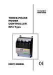
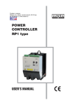
GTR-82 Generator Controller Owner’s Manual Web Site:http://www.monicon.com.tw E-mail:[email protected] 1 Table of contents 1 2 3 Introduction......................................................................................................................... 1 1.1 GTR-82 Panel .......................................................................................................... 1 1.1.1 Indicators....................................................................................................... 1 1.1.2 Rotary Switch Function ................................................................................. 1 1.1.3 Push-Button Function.................................................................................... 1 1.2 Wire Terminal ........................................................................................................... 1 1.3 CASE DIMENSIONS ............................................................................................... 3 1.4 Specifications ........................................................................................................... 3 1.4.1 General ......................................................................................................... 3 1.4.2 Controller Function ........................................................................................ 3 1.4.3 Network function: .......................................................................................... 4 1.4.4 Panel function: .............................................................................................. 4 1.4.5 Protection function: ....................................................................................... 4 1.5 Wiring....................................................................................................................... 4 1.5.1 Wiring example ............................................................................................. 4 1.5.2 Connection in short distance ......................................................................... 5 1.5.3 Connection with modem................................................................................ 5 1.5.4 Inside fuse and protecting value.................................................................... 5 1.5.5 Group connection .......................................................................................... 5 Communication protocol for user monitoring ...................................................................... 6 2.1 Communication Interface ......................................................................................... 6 2.1.1 Connect with GTR82 via RS-485 interface.................................................... 6 2.1.2 Transmit information via MTR-1 .................................................................... 7 2.1.3 C8 command description............................................................................... 8 2.1.4 Example for AC line voltage, phase voltage, and current readout ............... 10 Software manual............................................................................................................... 14 3.1 GTR82 software installation ................................................................................... 14 3.2 GTR82 software description................................................................................... 15 3.2.1 Button.......................................................................................................... 15 3.3 Parameters description .......................................................................................... 17 3.3.1 System page ............................................................................................... 17 3.3.2 Input page ................................................................................................... 23 3.3.3 Output page ................................................................................................ 26 3.3.4 Misc. page................................................................................................... 28 i 1 Introduction 1.1 GTR-82 Panel 1.1.1 Indicators Light Test Power Test lights for solid, clear and brightness. It also tests alarm. Run Stop Reset Trip 1. First time “Reset” shutdown the alarm. Second time “Reset” clears fault lights. Alarm Over Crank High Water Temp. 2. Holding down for a longer period will produce 1st and 2nd time “Reset” functions. Over Speed 3. Turn on the LCD backlight. Low Oil Pressure 1.1.2 Rotary Switch Function Network Allow online authorized user entry to perform monitoring and control. ATS The engine starts automatically, when shorted ATS1 and ATS2 terminal behind the controller under ATS mode. Manual User starts the engine directly. Off Shutdown the engine or forbid start function. 1.1.3 Push-Button Function PAGE Figure 1 – GTR82 Panel Change LCD display page for reading more information. 1.2 Wire Terminal Figure 2 – GTR82 wire terminal 1 Table 1 – GTR82 back description 1 2 3 4 5 6 7 8 9 10 11 Symbol ++ GND Motor Valve Output 3 Output 2 Alarm Trip 1 Trip 2 Input 2 Input 0 Continental terminal description Description Symbol DC power (Battery +) 21 R Ground (Battery -) 22 S Output, starter relay 23 T Output, fuel valve relay 24 N Output, Aux 3 relay 25 R.CT. L Output, Aux 2 relay 26 R.CT. S Output, alarm relay 27 S.CT. L Output, electrical trip relay 28 S.CT. S Output, electrical trip relay 29 T.CT. L Digital input, Aux 2 switch 30 T.CT. S Digital input, Aux 0 switch 31 F.L. Sen. 12 Input 3 Digital input, Aux 3 switch 32 W.T. Sen. 13 L.O.P. 33 O.P. Sen. 14 H.W.T. 34 Spare 15 16 17 ALT. Input 1 ATS 1 Digital input, Low oil press. switch Digital input, High water temp. switch Digital input, Alternator plus Digital input, Aux 1 switch Digital input, shorted with ATS2 18 ATS 2 19 F.D. 1 20 F.D. 2 Symbol 35 36 37 Spare Spare Output 0_2 Digital input, shorted with ATS1 38 Output 0_1 Analog input, Frequency detect 39 Output terminal 1_2 Analog input, Frequency detect 40 Output terminal 1_1 VARIABLE REGISTER DESCRITOPN Description Symbol AC voltage calibration AC Ampere calibration Water Temp. calibration Description Analog input, R phase volt Analog input, S phase volt Analog input, T phase volt Analog input, N phase volt Analog input, R line current (L) Analog input, R line current (S) Analog input, S line current (L) Analog input, S line current (S) Analog input, T line current (L) Analog input, T line current (S) Analog input, Fuel level sensor (option) Analog input, Water temp. sensor Analog input, Oil pressure sensor Spare Spare Spare Output, Aux. 0 relay Output, Aux. 0 relay Output, Aux. 1 relay Output, Aux. 1 relay Description Oil Pressure calibration Fuel Level calibration DC POWER STATUS DESCRIPTION Description Symbol OK: Solid “green” LED DC power polarity fault RS-485 COMMUNICATION PORT Description Symbol 1. Battery + 2. A 3. B 4. GND Note: 1. Output Relay function can be changed according users requirements. 2. Output Trip Relay is intended to be used to trip the Breaker or AVR filed current in order to cut off load to the generator. 3. VRs are adjustment for matching tolerance between external and internal measuring meter readout. 2 1.3 CASE DIMENSIONS Figure 3 – GTR82 side view Figure 4 – GTR82 back view 1.4 Specifications 1.4.1 Operating Temperature Range: General -30 ℃ ~ +70 ℃ DC Supply: 8 ~ 36 VDC Dimension (W x H x D): Power Consumption: 144 mm x 144 mm x 74 mm Max. 10 W Panel Cut-out (W x H): Measuring Voltage: 138 mm x 138 mm 10 ~ 300 VAC (Phase to Neutral, Accuracy 1.5 %) Weight: Measuring Current: 1.4 Kg (3.08 lb.) 1.4.2 ../5 A (secondary current readout below 0.15 A shows zero on LCD display. Accuracy 1.5 %) Controller Function LCD display: Measuring Frequency: 1. Three phase-phase voltage 0 ~ 80 Hz (Min AC Volt: 8 V) 2. Three line current Charger AC Output Voltage Sensitivity: 3. Three phase-neutral voltage 3 V ~ 70 V Peak to Peak 4. Frequency Charger AC Output Frequency Sensitivity: 5. RPM 62 Hz ~ 10,000 Hz 6. Battery Voltage Relay Output: 7. Run hours 10 A /30 VDC 8. Coolant Temperature Software Platforms: 9. Oil Pressure Windows 98, Windows ME, Windows 2000, Windows XP (recommend) 10. PF 11. KW Communication Protocol: 12. KWH RS-485 (Dynamic encryption by Monicon technology) 13. KVAR 3 14. KVA 1.4.3 4. Low water level protection 5. Over speed protection Network function: Remote start/stop the controller by two wires network circuitry Generator respect: 1. Over load protection Parameter setting and reading 2. Short circuit protection Input and output monitor 3. Over voltage protection Fault history readout 4. Under voltage protection Data acquisition can be done from a remote site 1.4.4 5. High frequency protection 6. Low frequency protection Panel function: Manual start / stop engine. Battery respect: Automatically start / stop engine by ATS. 1. Low battery indicator/ alarm Reset the controller. 2. High battery indicator/ alarm Light test. 3. Charge failure indicator 1.4.5 4. Start prohibit on weak battery power Protection function: Engine respect: Peripheral respect: 1. Over crank protection 1. Lower fuel level protection 2. Low oil pressure protection 2. Aux. 2 3. High water temperature protection 3. Aux. 3 1.5 Wiring 1.5.1 Wiring example Figure 5 – GTR82 wiring diagram 4 1.5.2 Connection in short distance Figure 6 – GTR82 local connection diagram 1.5.3 Connection with modem Figure 7 – GTR82 remote connection diagram 1.5.4 Inside fuse and protecting value Fuse1:100 mA Fuse2:750 mA Fuse3:6 A 1.5.5 Group connection 1. Every controller must be have its own identified number to support software recognition. Go to System / Misc. page, and change its id number. 2. Group wiring: The MTR-1 terminal pin 1 and pin 4 are the power supplied ports, so just one MTR-1 needs to be connected with pin 1,2,3,4, and others connect with pin 2, 3 only. 5 Figure 8 – Group connection diagram Note: It is strong suggestion that using another power source to power the communication card (MTR-1), If the wire length over 25 meters. This prevents the MTR-1 go in an unpredictable condition by voltage drop. 2 Communication protocol for user monitoring (start) 2.1 Communication Interface 2.1.1 Connect with GTR82 via RS-485 interface Connection method1 Master device (RS-485) Ù GTR82 as slave device (RS485) Master device UART configuration 9600 bps, no parity, 9 data bits, 1 stop bits The leading 8 bits information defines as “Address”, when the 9th bit sets to 1 (or logic high), and it defines as “Data” when the 9th bit sets to 0 (or logic low). Information transmitting format The master device transmitting information form includes three parts that are Address, Command as well as Data in three bytes. Address represents the GTR82’s identified number. Command represents with function group that master device invoke to be executed. Data represents which exactly command that master device invoke to be executed. Encryption processing Each byte of the transmitting information must be encrypted as follow; let’s say FID, the factory ID number, is 6 0x6F. Data processing Address = Address XOR FID Command = Command XOR FID Data = Data XOR FID Example Address = 0x41 XOR 0x6F = 0x2E Command = 0xC8 XOR 0x6F = 0xA7 Data = 0x05 XOR 0x6F = 0x6A For example, the master device transmits information to GTR82 controller via RS485 should be 0x2E then 0xA7 and then 0x6A as sequence. Information receiving format The master device receiving information form includes two parts Echo and Check. Echo represents the information that GTR82 responds to the master device transmitting information. Check is used for master device checks the accuracy of the receiving information. Receiving information processing Data processing Echo = Echo XOR FID Check = Check XOR FID Example Echo = 0x6F XOR 0x6F = 0x00 Check = 0x91 XOR 0x6F = 0xFE The master device receives information from GTR82 controller via RS485 should be 0x00 and then 0xFE. 2.1.2 Transmit information via MTR-1 Connection method 2 Master device (RS-232) Ù MTR-1 as interface (RS232 ÅÆ RS-485) Ù GTR82 controller as slave device (RS485) Device port configuration 19200 bps, no parity, 8 data bits, 2 stop bits Information transmitting format The master device transmitting information form includes four parts that are Start, Address, Command as well as Data in seven bytes. Format Example Transmitted information Start Address Command 4 1 C 8 | Function 0 5 The start byte, ‘|’ (0x7C in hexadecimal form), is the synchronous character of the MTR-1. The description of Address, Command and Data are the same as defined in section 2.1.1. All transmitting information should be transfer from hexadecimal to two ASCII characters, for example, if the Address is 0x41, then the transmitting data is ‘4’ ‘1’, or 0x34 0x31 in hexadecimal form. Encryption process Data processing Example Split into two ASCII characters Address = Address XOR FID Address = 0x41 XOR 0x6F = 0x2E 2E Command = Command XOR FID Command = 0xC8 XOR 0x6F = 0xA7 A7 Data = Data XOR FID Data = 0x05 XOR 0x6F = 0x6A 6A The master device transmits information to GTR82 controller via MTR-1 interface should be ‘|’ ‘2’ ‘E’ ‘A’ ‘7’ ‘6’ ‘A’ in character way, or 0x7C 0x32 0x69 0x65 0x67 0x66 0x65 in binary way. Information receiving format The format of receiving information form MTR-1 includes four bytes, and is combined with Echo and Check two parts. The descriptions of Echo and Check are the same as defined in section 2.1.1. Format Example Received information Echo Check 6 F 9 1 7 Receiving information processing 1. Transfer the two ASCII characters of the Echo part into one byte, for example ‘6’ ‘F’ Î 0x6F. 2. Transfer the two ASCII characters of the Check part to one byte, for example ‘9’ ‘1’ Î 0x91. 3. XOR process, Echo = Echo XOR FID, Check = Check XOR FID. 4. Check the accuracy of the receiving information. The receiving information is correct, only when the value of the de-encrypted information is equal to 0xFE. 2.1.3 C8 command description Code Description 17 Hundreds number of the KWH 00 Controller Type 18 Tens number of the KWH The readout value represents the type of the GTR controller. The value 0x80 represents the controller is GTR80, 0x82 represents the controller is GTR82, … etc. 19 Units number of the KWH 1B RPM high byte calculated from frequency 01 Current page of LCD 1C RPM low byte calculated from frequency 02 R-S voltage low byte 1D Battery voltage 03 S-T voltage low byte 04 T-R voltage low byte 05 R-S voltage high byte 06 S-T voltage high byte 07 T-R voltage high byte 08 Integral of frequency 09 Decimal of frequency 0A R-N voltage 0B S-N voltage 0C T-N voltage 0D Power factor 1A The battery voltage is calculated from the readout value divided 5. 1E 1F Each digit represents an output relay status, 0: off; 1: on. Bit 0: Aux. output 0 Bit 1: Aux. output 1 Bit 2: Aux output 2 Bit 3: Trip relay Bit 4: Alarm output Bit 5: Aux. output 3 Bit 6: Motor output Bit 7: Valve output The value 102 represents that wiring is wrong. 20 The value 101 represents that Power factor is lead. 21 22 The value between 100 and 55 represents current power factor, and the power factor is value / 100. Thousands number of the KW 0F Hundreds number of the KW 10 Tens number of the KW 11 Units number of the KW 12 Decimal point of the KW 13 Decimal of the KW 14 Hundred thousands number of the KWH 15 Ten thousands number of the KWH 16 Thousands number of the KWH Indicator status of group A Each bit represents a light on the penal, 0: off; 1: on. Bit 0: Run indicator Bit 1: Stop indicator Bit 2: Trip indicator Bit 3: Alarm indicator Bit 4: Over crank indicator Bit 5: High water temperature indicator Bit 6: Over speed indicator Bit 7: Low oil pressure indicator The value 55 represents power factor under 0.55. 0E Digital output status 23 24 25 8 26 Second number of run hour 27 Minute number of run hour 28 Hour number of run hour 29 100 hour number of run hour 37 Tens number of the KVA 2A R phase current low byte 38 Hundreds number of the KVA 2B S phase current low byte 39 Thousands number of the KVA 2C T phase current low byte 3A RPM low byte calculated by charger 2D R phase current high byte 3B RPM high byte calculated by charger 2E S phase current high byte 3C 2F T phase current high byte 3D 30 Value of coolant temperature 3E System information The value 0xFF (255) represents the coolant temperature sensor is open. 3F Value of lubricant temperature The value 0xFF (255) represents the lubricant temperature sensor is open. The value 0xFE (254) represents the coolant temperature is over 120 ℃. The value 0xFE (254) represents the lubricant temperature is over 120 ℃. The value 0xFD (253) represents the coolant temperature is below 40 ℃. The value 0xFD (253) represents the lubricant temperature is below 40 ℃. The value 0xFC (252) represents the coolant temperature sensor is short. The value 0xFC (253) represents the lubricant temperature sensor is short. The other value represents current coolant temperature, for example, the readout value is 0x55 (85) that represents 85 ℃. 31 The other value represents current lubricant temperature, for example, the value is 0x55 (85) that represents 85 ℃. Value of lubricant pressure The value 0xFF (255) represents the lubricant pressure sensor is open. 40 Trip code 41 Alarm code 42 U-V voltage low byte The value 0xFD (253) represents the lubricant pressure is 0 PSI. 43 V-W voltage low byte 44 W-U voltage low byte The value 0xFC (252) represents the lubricant pressure sensor is short. 45 U-V voltage high byte 46 V-W voltage high byte 47 W-U voltage high byte 48 Remote run down-count counter 49 Remote run down-count aide counter The value 0xFE (254) represents the lubricant pressure is over 150 PSI. The other value represents current lubricant pressure, for example, the readout value 0x55 (85) represents 85 PSI. 32 Value of fuel level The value 0xFF (255) represents the fuel level sensor is open. 4A 4B The value 0xFE (254) represents the fuel level is full. 4C The value 0xFD (253) represents the fuel level is empty. 4D The value 0xFC (252) represents the fuel level sensor is short. 4F 4E The other value represent current coolant level, for example, the readout value is 0x55 (85) that represents 85 %. 33 Maximum page of LCD 34 Decimal of the KVA 35 Decimal point of the KVA 36 Units number of the KVA 9 50 U-N voltage 51 V-N voltage 52 W-N voltage 53 Ratio of AC voltage Mask readout value with binary value 11111000B and right shift 3 digits to get the voltage ratio index. Ratio index = readout value >> 3 Ratio System index voltage Line voltage ratio 0 110V 0.01 1 120V 0.01 2 190V 0.01 3 208V 0.01 4 220V 0.01 5 380V 0.01 6 440V 0.02 7 480V 0.02 8 3300V 0.1 9 660V 0.03 Ratio of current transformer 54 Phase voltage ratio 1 1 1 1 1 1 2 2 10 3 Ratio index CT ratio 0 1 2 3 4 5 6 7 8 9 10 11 12 13 14 20:5 30:5 40:5 50:5 60:5 80:5 100:5 150:5 200:5 300:5 400:5 500:5 600:5 800:5 900:5 CT ratio 15 16 17 18 19 20 21 22 23 24 25 26 27 28 1000:5 1500:5 2000:5 3000:5 4000:5 5000:5 6000:5 10:5 15:5 75:5 250:5 750:5 1200:5 2500:5 Mask readout value with binary value 11111000B and right shift 3 digits to get the current ratio index. Ratio index = readout value >> 3 2.1.4 Example for AC line voltage, phase voltage, and current readout R-S voltage readout 1. Let’s say the GTR82 controller address is 0x41, the factory ID number (FID) is 0x6F, the RS voltage is 220V and the system voltage is 220V. 2. Get the voltage ratio: a. Master device should send 0x41 0xC8 0x53 as an original command and data. b. After encryption factory ID number 0x6F, the command should like 0x2E 0xA7 0x3C. c. Receiving information: i. Master device via MTR-1 connect to GTR82: The transmitting information should be “| 2 E A 7 3 C”. The receive Echo and Check are “4F91”. The receiving information is “20FE” after encrypt with factory ID number (FID, 0x6F). ii. Master device direct connect to GTR82: The command transmitting information should be 0x2E 0xA7 0x3C. The receive Echo and Check are 0x4F 0x91. The receiving information is 0x20 0xFE after encrypt with factory ID number, FID 0x6F. d. The readout of voltage ratio is 0x20 (32). e. Mask the Echo value with binary value 11111000B and right shift three digit, and the answer is 0x04. f. Check the look up table and get the ratio 0.01 and the system volt is 220V. 3. Get the R-S voltage low byte: a. Master device should send 0x41 0xC8 0x02 as an original command and data. b. After encryption factory ID number 0x6F, the command should like 0x2E 0xA7 0x6D. c. Receiving information: i. Master device via MTR-1 connect to GTR82: The transmitting information should be “| 2 E A 7 6 D”. The receive Echo and Check are “9F91”. The receiving information is “F0FE” after encrypt with factory ID number, FID 0x6F. ii. Master device direct connect to GTR82: The command transmitting information should be 0x2E 0xA7 0x6D. The receive Echo and Check are 0x9F 0x91. The receiving information is 0xF0 0xFE 10 after encrypt with factory ID number, FID 0x6F. d. The readout of R-S voltage low bye is 0xF0 (240). 4. Get R-S voltage high byte: a. Master device should send 0x41 0xC8 0x05 as an original command and data. b. After encryption factory ID number 0x6F, the command should like 0x2E 0xA7 0x6A. c. Receiving information: i. Master device via MTR-1 connect to GTR82: The transmitting information should be “| 2 E A 7 6 A”. The receive Echo and Check are “3A91”. The receiving information is “55FE” after encrypt with factory ID number, FID 0x6F. ii. Master device direct connect to GTR82: The command transmitting information should be 0x2E 0xA7 0x6A. The receive Echo and Check are 0x3A 0x91. The receiving information is 0x55 0xFE after encrypt with factory ID number, FID 0x6F. d. The readout of R-S voltage low bye is 0x55 (85). 5. Combine the voltage high and low byte to get the RS true value. a. High byte contribute value is 256 * 85 = 21760. b. Low byte contribute value is 240. c. The voltage ratio is 0.01. d. So the answer is (21760 + 240) * 0.01 = 220 V R-N voltage readout 1. Let’s say the GTR82 controller address is 0x41, the factory ID number, FID is 0x6F, the RN voltage is 127V and the voltage ratio is 220V. 2. Get the voltage ratio: a. Master device should send 0x41 0xC8 0x53 as an original command and data. b. After encryption factory ID number 0x6F, the command should like 0x2E 0xA7 0x3C. c. Receiving information: i. Master device via MTR-1 connect to GTR80: The transmitting information should be “| 2 E A 7 3 C”. The receive Echo and Check are “4F91”. The receiving information is “20FE” after encrypt with factory ID number, FID 0x6F. ii. Master device direct connect to GTR80: The command transmitting information should be 0x2E 0xA7 0x3C. The receive Echo and Check are 0x4F 0x91. The receiving information is 0x20 0xFE after encrypt with factory ID number, FID 0x6F. d. The readout of voltage ratio is 0x20 (32). e. Mask the Echo value with binary value 11111000B and right shift three digit, and the answer is 0x04. f. Check the look up table and get the ratio 1 and the system volt is 220V. 3. Get the R-N voltage: a. Master device should send 0x41 0xC8 0x0A as an original command and data. b. After encryption factory ID number 0x6F, the command should like 0x2E 0xA7 0x65. c. Receiving information: i. Master device via MTR-1 connect to GTR82: The transmitting information should be “| 2 E A 7 6 5”. The receive Echo and Check are “1091”. The receiving information is “7FFE” after encrypt with factory ID number, FID 0x6F. ii. Master device direct connect to GTR82: The command transmitting information should be 0x2E 0xA7 0x65. The receive Echo and Check are 0x10 0x91. The receiving information is 0x7F 0xFE after encrypt with factory ID number, FID 0x6F. d. The readout of R-N voltage is 0x7F (127) 4. The answer is 127 * 1 = 127V 11 R-phase current readout 1. Let’s say the GTR82 controller address is 0x41, the factory ID number, FID is 0x6F, the R-phase current is 365A and the current ratio is 400:5. 2. Get the current ratio: a. Master device should send 0x41 0xC8 0x54 as an original command and data. b. After encryption factory ID number 0x6F, the command should like 0x2E 0xA7 0x3B. c. Receiving information: i. Master device via MTR-1 connect to GTR82: The transmitting information should be “| 2 E A 7 3 B”. The receive Echo and Check are “3F91”. The receiving information is “50FE” after encrypt with factory ID number, FID 0x6F. ii. Master device direct connect to GTR82: The command transmitting information should be 0x2E 0xA7 0x3B. The receive Echo and Check are 0x3F 0x91. The receiving information is 0x50 0xFE after encrypt with factory ID number, FID 0x6F. d. The readout of current ratio is 0x50 (80). e. Mask the Echo value with binary value 11111000B and right shift three digit, and the answer is 0x0A. f. Check the look up table and get the ratio 400:5, and the full scale is 400. 3. Get the R-phase current low byte: a. Master device should send 0x41 0xC8 0x2A as an original command and data. b. After encryption factory ID number 0x6F, the command should like 0x2E 0xA7 0x45. c. Receiving information: i. Master device via MTR-1 connect to GTR82: The transmitting information should be “| 2 E A 7 4 5”. The receive Echo and Check are “2D91”. The receiving information is “42FE” after encrypt with factory ID number, FID 0x6F. ii. Master device direct connect to GTR82: The command transmitting information should be 0x2E 0xA7 0x45. The receive Echo and Check are 0x2D 0x91. The receiving information is 0x42 0xFE after encrypt with factory ID number, FID 0x6F. d. The readout of R-phase current low bye is 0x42 (66). 4. Get the R-phase current high byte: a. Master device should send 0x41 0xC8 0x2D as an original command and data. b. After encryption factory ID number 0x6F, the command should like 0x2E 0xA7 0x42. c. Receiving information: i. Master device via MTR-1 connect to GTR82: The transmitting information should be “| 2 E A 7 4 2”. The receive Echo and Check are “6191”. The receiving information is “0EFE” after encrypt with factory ID number, FID 0x6F. ii. Master device direct connect to GTR82: The command transmitting information should be 0x2E 0xA7 0x42. The receive Echo and Check are 0x61 0x91. The receiving information is 0x0E 0xFE after encrypt with factory ID number, FID 0x6F. d. The readout of R-phase current high bye is 0x0E (14). 5. Calculate the R-phase current by the following procedure: if (full scale <= 80) { R-phase current = (256 * current-high-byte + current-low-byte) / 100; Current display format is XX.X A } else if (full scale <= 200) { R-phase current = (256 * current-high-byte + current-low-byte) / 100; Current display format is XXX.X A } 12 else { R-phase current = (256 * current-high-byte + current-low-byte) / 10; Current display format is XXXX A } So, the answer is (256 * 14 + 66) / 10 = 3650 / 10 = 365 A. (end) 13 3 Software manual 3.1 GTR82 software installation 1. Step 1: open the GTR80 installation folder and double click the file “setup.exe”. The setup wizard will guide you to finish the whole installing process. 4. Step 4: 5. Step 5: restart computer. 2. Step 2: welcome screen. 3. Step 3: choose the destination folder. 14 3.2 GTR82 software description 3.2.1 Button Connection The connection config window will display after clicked this button. User need to be set comport, connection method and controller ID. Then click “Connect” button makes the communication working between controller and computer. Save file Save the configuration of GTR82 in to a file as a record or a configuration library. Remote start When the connection between GTR82 and software is setup, User can remote start engine by two ways: Local connection setting window 1. Enable the “Remote start run-time interval” item then click OK. The engine will be started at next second, and will be stopped until the timer is expired, or click the remote stop button. 2. Click OK directly, the engine will be started and will be stopped if the communication is failed or click the remote stop button. Note: Communication may fail by many reasons, so it is strong suggestion that using method 1 to remote start the engine. Remote connection window Disconnection Click this button cuts off connection between computer & controller Remote stop Open file Click this button shuts down the running engine that by network remote start. Open an existed configuration file of GTR82. It is convenience for configuring the GTR82 controller with the same requirement. Reset Click this button clears the fault indicate and set the whole system in a normal status. Panel Click this button shows the controller’s panel and all real time information. 15 read from the GTR82 controller. Set all parameters Click this button, all configuration settings will be written into the GTR82 controller. About Click this button shows the information of the Monicon instruments Co., Ltd. and the version of the GTR82 software. Read parameters Setting Click this button reads all the parameters in the current page that user selects. Click this button shows the configuration screen. Set parameters Click this button configures all the parameters in the current page that user selects. Refresh - After configuring settings to the GTR82 controller, the settings are in the un-working memory. Click this button lets the GTR82 controller to refresh its settings into the running procedure. Clear MSG Click this button clears the texts in the message box. Read all parameters Click this button, all configuration settings will be 16 3.3 Parameters description 3.3.1 System page Crank page Item 1 2 3 4 5 6 7 8 Name Default Range Cranking time 10 Sec. 3 ~ 20 Sec. Idle duration 10 Sec. 5 ~ 600 Sec. Crank disconnect 20 Hz 15 ~ 30 Hz beyond frequency Crank enable minimum 20 Hz 15 ~ 30 Hz frequency Crank attempt 3 1 ~ 10 Detect alternate Checked Checked / frequency Un-checked Detect Lubricant Un-checked Checked / pressures sw. Un-checked Lubricant pressures sw. 1.5 Sec. 0.5 ~ 6.25 Sec. escape starter Description Set the maximum limitation of the cranking time. The interval of the idle running. When frequency goes above this setting, the starter motor will escape. When frequency is below this setting the starter motor will be activated during cranking interval. Total cranking attempts. Checked means enable this function. Controller escapes starter motor refers to frequency value. Controller escapes starter motor refers to lubricant pressure built up. If the system’s setting “Detect Lubricant Pressure sw.” is enabled, when oil pressure switch is activated and the active period is longer than this setting, the controller will escape the starter motor during crank interval. This setting is nothing to do with low oil pressure delay. Freq. page Item Name Default Over frequency 1 Checked box Checked 2 3 Action mode Setting Stop 66 Hz 55 Hz Range Description Checked / Checked means enable this function. Un-checked Un-changeable 60 ~ 72 Hz 60 Hz system 50 ~ 60 Hz 50 Hz system 17 Item Name 4 Timer Low frequency 5 Checked box 6 Action mode 7 Setting Default Range 2 sec. 1 ~ 10 Sec. Checked Indicate 54 Hz 45 Hz 6 Sec. 8 Timer Minimum detect frequency 9 Checked box Checked 10 Setting 30 Hz 11 60 Hz System frequency Description Checked / Checked means enable this function. Un-checked There are four kind action mode can be selected. Stop*, Trip†, Alarm‡, Indicate§ 48 ~ 59 Hz 60 Hz system 40 ~ 50 Hz 50 Hz system 1 ~ 10 Sec. Checked / Checked means enable this function. Un-checked 10 ~ 45 Hz Low frequency protection will be disabled if frequency is under this setting. 50 / 60 Hz Rated frequency of the generator system. Sensor page Item Name Default 1 Low fuel level Checked box 2 Setting 3 Low lubricant pressure Checked box Un-Checked 4 Setting 5 High coolant temperature Checked box Un-Checked 6 Setting 7 8 Temperature unit Pressure unit Un-Checked 20 % 20 PSI 95 ℃ ℃ PSI Range Description Checked / Checked means enable this function. Un-checked 6 ~ 55 % Controller gives an alarm signal when this function is enabled and the fuel level is under this setting. Checked / Checked means enable this function. Un-checked 15 ~ 60 PSI Controller gives an alarm signal when this function is enabled and the value of the lubricant pressure sensor is under this setting. Checked / Checked means enable this function. Un-checked 85 ~ 110 ℃ Controller gives an alarm signal when this function is enabled and the value of the coolant temperature sensor is over this setting. ℃ / ℉ The unit of the temperature on the LCD display. PSI / BAR The unit of the pressure on the LCD display. * Stop means controller shuts down the engine when the function is activated. † Trip means controller gives an open signal via Trip output (Trip output is normal close relay) when the function is activated. ‡ Alarm means controller gives a warning signal via Alarm output when the function is activated. § Indicate means controller indicates the fault signal via the indicator of the panel when the function is activated. 18 Item 9 Name Escape lubricant pressure Checked box Un-Checked 10 Setting 11 Default F.L. input select 35 PSI Fuel level sensor 12 Brand of lubricant pressure sensor SUSUKI 13 Brand of coolant temperature sensor SUSUKI 14 Detect sensor status when power on 15 Display F.L. input Checked Checked Range Description Checked / Checked means enable this function. Un-checked 25 ~ 65 PSI Controller escapes the starter motor when the value of the lubricant pressure sensor is greater than this setting. Fuel level sensor Lubricant temp. sensor SUSUKI PRO VDO 10 BAR VDO 5 BAR SCD SUSUKI PRO VDO SCD Checked / Un-checked Use fuel level sensor as the F.L. input. Use lubricant temperature sensor as the F.L. input. GTR82 supports five brand of the lubricant pressure sensor. GTR82 supports four brand of the coolant temperature sensor. Checked means enable this function. Checked / Checked means display fuel level value or lubricant Un-checked temperature depends on selecting. AC volt page Item Name Default 1 3 Checked box Checked 2 3 Action mode Setting 4 Timer Trip 121 V 131 V 207 V 228 V 242 V 416 V 484 V 525 V 3632 V 726 V 2.5 Sec. Range Description Checked / Checked means enable this function. Un-checked Refer to the description in *, †, ‡, §. 110 ~ 128 V AC 110 V system 119 ~ 138 V AC 120 V system 190 ~ 219 V AC 190 V system 207 ~ 240 V AC 208 V system 219 ~ 254 V AC 220 V system 378 ~ 439 V AC 380 V system 439 ~ 512 V AC 440 V system 477 ~ 553 V AC 480 V system 2197 ~ 3823 V AC 3300 V system 659 ~ 762 V AC 660 V system 0.25 ~ 10 Sec. 19 Item Name 5 Under voltage Checked box 6 7 Action mode Setting 8 9 Checked Trip 98 V 107 V 171 V 186 V 197 V 340 V 394 V 432 V 2958 V 591 V Timer 2.5 Sec. Voltage detect minimum Checked box Checked 10 Setting 11 Default System voltage Escape voltage 12 Checked box 13 Setting 34 V 39 V 62 V 62 V 72 V 124 V 145 V 159 V 1089 V 217 V 220 V Un-checked 93 V 100 V 160 V 176 V 186 V 321 V 373 V 404 V 2802 V 560 V Range Description Checked / Checked means enable this function. Un-checked Refer to the description in *, †, ‡, §. 91 ~ 110 V AC 110 V system 100 ~ 119 V AC 120 V system 159 ~ 190 V AC 190V system 174 ~ 207 V AC 208 V system 185 ~ 219 V AC 220 V system 318 ~ 378 V AC 380 V system 370 ~ 439 V AC 440 V system 401 ~ 477 V AC 480 V system 1851 ~ 3304 V AC 3300 V system 555 ~ 659 V AC 660 V system 0.25 ~ 10 Sec. Checked / Un-checked 25 ~ 72 V 29 ~ 79 V 46 ~ 124 V 51 ~ 136 V 53 ~ 145 V 93 ~ 252 V 107 ~ 290 V 117 ~ 318 V 813 ~ 2197 V 160 ~ 435 V 110 V 120 V 190 V 208 V 220 V 380 V 440 V 480 V 3300 V 660 V Checked / Un-checked 53 ~ 108 V 58 ~ 119 V 93 ~ 188 V 103 ~ 207 V 108 ~ 219 V 188 ~ 378 V 217 ~ 439 V 238 ~ 477 V 1643 ~3286 V 326 ~ 659 V Checked means enable this function. AC 110 V system AC 120 V system AC 190V system AC 208 V system AC 220 V system AC 380 V system AC 440 V system AC 480 V system AC 3300 V system AC 660 V system Connect directly. Under voltage protection is disabled when the value of the AC voltage is under this setting. Connect with transformer (440V / 220 V) Connect with transformer (480V / 240 V) Connect with transformer (3300V / 330 V) Connect with transformer (660V / 330 V) Checked means enable this function. AC 110 V system AC 120 V system AC 190V system AC 208 V system AC 220 V system AC 380 V system AC 440 V system AC 480 V system AC 3300 V system AC 660 V system 20 Controller escapes the starter motor when the value of AC voltage is greater than this setting if the escape voltage function is enabled. AC current page Item Name Default Range 400:5 10:5 ~ 6000:5 1 CT ratio 2 Over load Checked box Checked 3 Action mode Trip 4 5 348 A 40 Sec. 6 Setting Timer Short circuit Checked box Checked 7 Action mode Trip 8 9 Setting Timer 376 A 0.2 Sec. Description Select system current transformer ratio. Checked / Checked means enable this function. Un-checked Stop Trip Alarm Indicate 1 ~ 400 A The value depends on CT ratio which user selects. 10 ~ 2550 Sec. Checked / Checked means enable this function. Un-checked Stop Trip Alarm Indicate 1 ~ 400 A The value depends on CT ratio which user selects. 0.1 ~ 2 Sec. Hours page Item 1 2 3 4 Name Second Minute Hour 100 Hour Default 0 0 0 0 Range 0 ~ 59 0 ~ 59 0 ~ 99 0 ~ 99 Description 21 Engine page Item Name 1 Pre-add fuel time 2 Engine halt period Default 0 Sec. 2 Sec. 3 Cooling time 1 Sec. 4 Energies to stop 10 Sec. 5 Pre-heat timer 0 Sec. 6 Shutdown After Trip Checked box Checked 7 Timer 30 Sec. Range 0 ~ 10 Sec. 1~ 30 Sec. Description The interval of pre-add fuel before start engine. Engine will be halt a period of time after system shut down by fault occurred. 1 ~ 240 Sec. After normal shut down the engine, the cooling procedure will be activated. Cooling time will be no used in fault shut down or by manual switch off. 1 ~ 20 Sec. The timer is setting how long the fuel solenoid should be energized to stop the engine completely 0 ~ 60 Sec. The Pre-Heat procedure will be activated and the AUX. relay outputs if signet. Checked / Checked means enable this function. Un-checked 30 ~ 900 Sec. When trip activated the Run light will flash and trip relay energized, the control will shut down the engine if fault not clear before the setting time is up. Battery page Item Name Default 1 Low battery volt 19.2 V setting 2 High Battery Volt. 30 V Setting 3 System DC Volt. 24 V 4 Charge Fail 25.2 DCV 5 Week battery power Checked box Checked Range 7.6 ~ 26 V 12 ~ 32 V 12V / 24V 11 ~ 26 V Description DC volts under this setting value will cause warning or alarm depends on setting. DC volts above this setting value will cause warning or alarm depends on setting. Sets the minimum charger output voltage while engine running. The action mode is Indicate. Checked / Checked means enable this function. Un-checked 22 Item Name 6 Setting 7 Battery fail Default 16.8 V Alarm Range Description 7.6 V ~ 23 V During the crank interval, if DC voltage drop below this setting exceeds cranking time minus one second then GTR82 will shut down the engine and display “DC weak power”. Indicate Controller gives an alarm or indicate signal when the low Alarm battery or high battery occurred. RPM page Item Name Default 1 Over Speed Checked box Checked 2 3 Action mode Setting 4 7 Timer RPM ratio Multiple factor Divider factor Escape RPM Checked box 8 Setting 600 RPM 9 RPM display By Freq. 5 6 3.3.2 Range Description Checked / Checked means enable this function. Un-checked Stop Un-changeable 1980 RPM 1350 ~ 2100 Over speed detecting method is sensed alternator charger RPM RPM. IF over this setting then will cause engine stop. 2 Sec. 1 ~ 10 Sec. 56 10 Checked 1 ~ 200 1 ~ 200 Checked / Un-checked 400 ~ 1000 RPM By Freq. / By Charger The ratio of rotation of main frame versus alternator chargers’ pulley. Checked means enable this function. Controller escapes the starter motor when engine speed is greater this setting. The engine speed can be calculated by the AC frequency or by the alternator charger frequency depends on setting. Input page Sensor switch page 23 Item 1 2 3 4 5 6 7 8 Name Default Range Description High coolant temperature switch Checked box Checked Checked / Checked means enable this function. Un-checked Action mode Stop Un-changeable Type N.O. N.O. N.O.:This switch returns a closed signal during high water N.C. temperature conditions, once the engine water temperature is cool down the switch will open. N.C.:This switch returns an open signal during high water temperature conditions, once the engine water temperature is cool down the switch will close. Timer 1 Sec. 0.5 ~ 10 Sec. Low lubricant pressure switch Checked box Checked Checked / Checked means enable this function. Un-checked Action mode Stop Un-changeable Type N.O. N.O. N.O.:This switch returns a closed signal during low oil N.C. pressure conditions, once oil pressure is established the switch will open. N.C.:This switch returns an open signal during low oil pressure conditions, once oil pressure is established the switch will close. Timer 1.5 Sec. 0.125 ~ 12.5 Sec. Aux. input page Item Name Default 1 Auxiliary input 0 Checked box Checked Range Description Checked / Checked means enable this function. Un-checked 24 Item Name 2 Function name Default Emergency stop 3 Action mode Stop 4 Type N.C. 5 6 Timer Auxiliary input 1 Checked box 7 Function name 8 Action mode 9 Type 10 Timer Auxiliary input 2 11 Checked box 12 Function name 0.2 Sec. Description GTR82 supports the following function input as auxiliary input 0: Emergency stop, Low Battery Volt, High Fuel Level, Pre-Alarm, Charge fail, Over Load, Low Water Temp., and Spare. The function name Emergency stop is the special function for the auxiliary input 0. Controller shuts down the engine immediately when the Emergency stop switch is activated. Refer to the description in *, †, ‡, §. When function name, Emergency stop, is selected, the action mode is set as Stop and is un-changeable. N.C. N.O. 0.1 ~ 10 Sec Checked Checked / Checked means enable this function. Un-checked Battle switch See GTR82 supports the following function input as auxiliary description input 1: Battle switch, Low Battery Volt, High Fuel Level, Pre-Alarm, Charge fail, Over Load, Low Water Temp., and Spare. The function name battle switch is the special function for the auxiliary input 1. Controller bypassed the fault signal except the emergency stop and over speed when the battle switch input is activated and function name is selected. Stop Refer to the description in *, †, ‡, §. When function name battle switch is selected, the action mode is un-changeable. N.O. N.O. N.C. 1 Sec. 0.25 ~ 5 Sec Checked Low water level 13 Action mode 14 Type Stop N.O. 15 Timer Auxiliary input 3 16 Checked box 5 Sec. 17 Function name Range See description Checked Low fuel level 18 Action mode 19 Type Stop N.O. 20 Timer 5 Sec. Checked / Checked means enable this function. Un-checked See GTR82 supports the following function input as auxiliary description input 2: Low water level, Low Battery Volt, High Fuel Level, Pre-Alarm, Charge fail, Over Load, Low Water Temp., and Spare. Refer to the description in *, †, ‡, §. N.O. N.C. 0.5 ~ 10 Sec Checked / Checked means enable this function. Un-checked See GTR82 supports the following function input as auxiliary description input 3: Low fuel level, Low Battery Volt, High Fuel Level, Pre-Alarm, Charge fail, Over Load, Low Water Temp., and Spare. Refer to the description in *, †, ‡, §. N.O. N.C. 0.5 ~ 10 Sec 25 Operational switch page Name Default 1 ATS switch Checked box Checked 2 Timer 3 Manual switch Checked box Item 4 1 Sec. Checked 5 Timer Reset switch Checked box Checked 6 Timer 0.25 Sec. 3.3.3 1 Sec. Range Description Checked / Checked means enable this function. Un-checked 0.25 ~ 63.75 Sec. Checked / Checked means enable this function. Un-checked 0.25 ~ 5 Sec. Checked / Checked means enable this function. Un-checked 0.25 ~ 2.5 Sec. Output page Item Name 1 Aux. output 0 Default Error occur Range See description 2 Aux. output 1 Pre-heat duration See description 3 Aux. output 2 Energized to stop See description Description GTR82 supports the following function output as auxiliary output: 1. Error Occur, 2. Standby, 3. Pre-heat, 4. Start Period, 5. Start Interval, 6. Run, 7. Stop, 8. Engine Halt, 9. Generator Working, 10. Reset Activate, 11. System Trip, 12. System Alarm, 13. Fire Charger, 14. High Coolant Temp. Value, 15. Low Fuel Level Value, 16. Low Lube Press. Value, 17. Under Frequency Active, 18. High Voltage Active, 19. Under Voltage Active, 20. Over Load Active, 21. Short Circuit Active, 22. Error Occur (B), 23. Reserve 2, 24. Spare, 25. Engine 26 Item Name 4 Aux. output 3 5 Trip output Default Fire changer Range See description System trip See description Description Running, 26. Low Water Level Active, 27. Low Bat. Volt Active, 28. Low Fuel Level Active, 29. Over Crank, 30. High Coolant Temp. Active, 31. Over Speed Active, 32. Low Lube Press. Active, 33. Emergency Stop Active, 34. Not Auto Position, 35. Manual Start, 36. Auto Start, 37. Remote Position, 38. Reserve 3, 39. Reserve 4 Auxiliary output function description Item Function name 1 2 Error Occur Standby 3 4 5 Pre-heat Start Period Start Interval 6 7 Run Stop 8 Engine Halt 9 10 11 12 13 Generator Working Reset Activate System Trip System Alarm Fire Charger 14 High Coolant Temp. Value 15 Low Fuel Level Value 16 Low Lube Press. Value 17 18 19 20 21 22 23 24 25 26 Under Frequency Active High Voltage Active Under Voltage Active Over Load Active Short Circuit Active Error Occur (B) Reserve 1 Engine Running Aux. In 2 Active 27 Low Bat. Volt Active 28 Aux. In 3 Active 29 Over Crank 30 High Coolant Temp. Active Description An aux. output relay will be energized when engine stop by fault occurred. When system is under standby status, the aux. output relay energized and will be de-energized when escape standby mode. An aux. output relay will be energized during the pre-heat procedure. An aux. output relay will be energized during the starter motor is activated. An aux. output relay will be energized between the periods of two continuous cranking attempts. The time period is decided by the setting of the Energies to stop. An aux. output relay will be energized during the system is in running mode. An aux. output relay will be energized when accepts the stop command or in start interval mode. The time period is decided by the setting of the Energies to stop. An aux. output relay will be energized during the engine halt mode. The time period is decided by the setting of Engine halt. An aux. output relay will be energized while the reset button is pressed. An aux. output relay will be energized during system in the trip mode. An aux. output relay will be energized during system in the alarm mode. An aux. output relay will be energized to fire the charger. The time period of the output signal is from start command accepts to the safety on timer expired. An aux. output relay will be energized when the vale of the coolant temperature sensor is greater than the setting of the high coolant temperature. An aux. output relay will be energized when the vale of the fuel level sensor is less than the setting of the low fuel level. An aux. output relay will be energized when the vale of the lubricant pressure sensor is less than the setting of the low lubricant pressure. An aux. output relay will be energized when under frequency is occurred. An aux. output relay will be energized when high voltage is occurred. An aux. output relay will be energized when under voltage is occurred. An aux. output relay will be energized when over load is occurred. An aux. output relay will be energized when short circuit is occurred. It is the same function of Error Occur but reverse action. Reserve for the function extension in the future. An aux. output relay will be energized when the auxiliary input 2 activated and caused engine stop. An aux. output relay will be energized when low battery is occurred. An aux. output relay will be energized when the auxiliary input 3 activated and caused engine stop. An aux. output relay will be energized when over crank is occurred. An aux. output relay will be energized if there is a stop fault occurred due to high coolant temperature detected by high coolant temperature switch. 27 Item Function name Description 31 Over Speed Active 32 Low Lube Press. Active An aux. output relay will be energized when over speed fault is occurred. An aux. output relay will be energized if there is a fault occurred due to the low oil pressure detected by low oil pressure switch. An aux. output relay will be energized when the auxiliary input 0 activated and cause engine stop. An aux. output relay will be energized when rotary switch is not in auto position. An aux. output relay will be energized while system is running by manual start command. An aux. output relay will be energized while system is running by auto start command. An aux. output relay will be energized when rotary switch is in network position. An aux. output relay will be energized when the DC voltage is greater than the setting of high battery volt. An aux. output relay will be energized when system is in idle procedure. 33 Aux. In 0 Active 34 Not Auto Position 35 Manual Start 36 Auto Start 37 Remote Position 38 High Battery Volt 39 Idle 3.3.4 Misc. page Item Name 1 Safety on timer Default 10 Sec. 2 De-bounce 50 3 4 Controller Address System not auto 5 Low speed engine Un-checked 6 Not cooling while manual stop 41 H Checked Checked Range 3 ~ 20 Sec. Description All alarms are ignored until safety on timer expired, except the emergency stop, over speed. 5 ~ 200 De bounce time can avoid the interference by Electronic or magnetic. 01 ~ FF H Controller address is for identification while multiple controllers connected in the same network. Checked / Checked means enable this function. Un-checked Controller gives an alarm signal when the position of rotary switch is not in auto position. Checked / Checked means enable this function. Un-checked The frequency vale multiple 20 as engine speed if checked otherwise multiple 30. For example, if the rated frequency is 60.0 Hz and the low speed engine is checked, then the engine speed is equal to 1200 rpm (60.0 * 20 = 1200 rpm). Checked / Checked means enable this function. Un-checked While manual stop, the controller will stop the engine immediately if this function is enable. Otherwise the controller will run in to cooling mode. 28