1
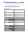
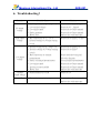
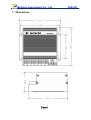
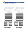
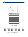
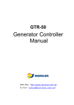
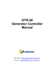
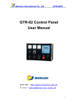
Monicon International Co., Ltd
AVR-051
AVR-051
User Manual
Web Site:http://www.monicon.com.tw E - m a i l :s a l e s @ m o n i c o n . c o m . t w
Monicon International Co., Ltd
AVR-051
1. Description:
The AVR-051 stabilizes the output voltage by detecting the phase output and make
necessary adjustments to the exciter accordingly. The AVR-051 is suitable for use on
brushless generator model.
2. Wiring:
:
The range of sensing the phase voltage (A, C) in the AVR-051 is AC 220 /380 /440
/480V. The input voltage for AVR-051 (B, C) is 100 ~ 300V AC, 50/60Hz. Please follow
the instructions and wiring diagram for the AVR-051 to prevent any malfunctions.
2.1. Input Terminals B、C are the power input for AVR-051. Terminals A、C are for
Genset voltage sensing and it can be wired independently (See figure 2) or in parallel if the
rated power output is AC 220V. (See figure 3 default setting)
※Note:
:Independent connection can reduce the adjustments
adjustments of voltage deficit
2.2. If the rated voltage output on the Genset is AC 380/440/480V,the voltage sensing
terminals must be wired independently as show on figure 4 and 5.
※Warning:
:The power input for AVRAVR-051
051 must not exceed 300V AC.
2.3. Connect output terminals(F+)、(F-) to the exciter on the generator (J, K)
2.4. External connector EXT.VR is for external potentiometer (1KΩ 1W VR) and must
be shorted when not in use.
※Warning:
:Please use AWG16 or 125mm 85℃
85℃ 600 V wire for connectors A、B、C、
F+、
F+、F-. For use on external potentiometer, please use insolated wires.
Monicon International Co., Ltd
AVR-051
3. Adjustments:
:
3.1 Frequency Setting:
:
Please switch PIN 1 on the frequency selector to “ON” position when rated
frequency is 50Hz (Please refer to Figure 8).
3.2 Voltage Setting:
:
Please switch pin 2 and pin 3 of the voltage selector to “ON” position when the rated
output phase voltage is 220V AC. (please refer to figure 2, 3, and 8)
Switch pin 2 to “ON” and pin 3 to “off” position on the voltage selector when rated
output phase voltage is 380V AC. (please refer to figure 4 and 8)
Switch pin2 and pin 3 to “OFF” position on the voltage selector when rated output
phase voltage is 440/480V AC. (please refer to figure 5 and 8)
※Warning:
Warning: Please pay extra attentions when setting
setting up the voltage and frequency
selectors;; incorrect settings could damage the AVR or the generator.
selectors
※Note:
Note:
Make sure all the wires, connections, and settings are all correct and turn
the VOLT and STAB fully
fully counterclockwise before starting the
generator.
3.3 Genset Voltage Fine Tune(VOLT):
:
After Genset has successfully started and in rated speed, slowly turn VOLT
clockwise to the rated voltage. (If EXT.VR is connected with a potentiometer, please
adjust the potentiometer to the center position)
3.4 Genset Stabilization Adjustment(STAB):
:
To adjust the feedback timing, slowly turn the STAB clockwise. We suggest using
analog DCV meter to monitor (F+) and (F-) then fine tune the meter until the movement
is at minimum. Over adjustment may cause unstable voltage output. Under adjustment
may have significant changes on the output voltage under heavy loads.
Monicon International Co., Ltd
AVR-051
3.5 Genset Low Frequency Setting(U/F):
:
Please do not adjust this setting, the U/F setting has been adjusted at the factory. Its
purpose is to activate the low frequency protection. When the output frequency of the
generator is lower than this setting, the AVR ceases the output automatically.
4. Excitation:
:
※ Warning:
Warning:Incorrect wiring of Genset or operation of the AVR for the first
(F--) is
time or the residual magnetism voltage is less than 5V or (F+) and (F
reversely;; the generator will not be able to build up voltage.
connected reversely
If the Genset can not build up the voltage, please shut down the generator and than
perform the following steps:
4.1. Please shut down the generator and check the wiring.
4.1.1 Incorrect wiring:Please rewire and than start the generator again.
4.1.2 If Genset still can not build up the voltage, please shut down the generator
and proceed to step 4.2.
4.1.3 If wiring is correct, please shut down the Genset and proceed to step 2.
4.2. Please shut down the generator before perform the following steps
4.2.1 Reverse (F+) and (F-) connections, than start the Genset again.
4.2.2 If Genset still can not build up the voltage, an external power source must be
used to excite the magnetism. Please make sure the generator has been
completely shut down before proceed to step 3.
4.3 . Please shut down the generator before perform the following steps
4.3.1 Disconnect AVR terminals (F+) and (F-), then use 3-12V DC (e.g. battery) as
power source and connect the positive terminal to a current limiting resistor
5~50Ω/30W, then connect to the positive terminal of the Genset and
negative to the negative terminal of the Genset. (Please refer to figure. 76)
Power up for 3 seconds and then disconnect the power source. Remove the
AVR power input and start the Genset. Wait until the rated idle speed, than
measure the residual magnetic voltage.
4.3.2 If the residual magnetic voltage is greater than 5V AC, please shut down the
Genset and reconnect the AVR than start the Genset again.
Monicon International Co., Ltd
AVR-051
4.3.3 If the residual magnetic voltage is less than 5V AC, please repeat step 3
again.
4.4. If the residual magnetic voltage is greater than 5V AC and the Genset still can not
build up the voltage, please replace with another AVR.
※Warning
Warning:
: Over excitation may damage the exciter or the AVR.
5. Specifications:
:
Voltage Detection Range(A、
、C) Voltage 220/380/440/480 VAC, single
phase 2 wires, Frequency 50/60 Hz
(Factory default setting: 220VAC, 60 Hz)
Input Voltage Range(B、
、C)
Voltage: 100~300 VAC single phase 2 wires
Frequency: 50/60 Hz
Voltage Adjustable Range
When External VR is 1KΩ and ±7%
Min. rated power is 1W
Voltage Adjustable Rate: < ±0.5 %
Min. Excitation Voltage: Residual voltage > 5 VAC
Magnetic Field
Field Output: Continuous current: 4.8A,intermittent: 5.2 A
Exciter Resistance: 15Ω(Min)
100Ω(Max)
Low Frequency Protection:
Protection Genset 60 Hz: Lower than 55Hz, AVR ceases
output (Default setting)
Genset 50 Hz: Lower than 45Hz, AVR ceases
output (Default setting)
EMI Protection: Build in EMI filter
Power Consumption: 8 Watt(Max)。
Fuse 6A / 250V / 20mm
Working Temperature: 0 ℃ ~ 65 ℃。
Storage Temperature: ﹣20 ℃ ~ 85 ℃。
Dimensions: W 93 * H 57 * D 110 mm。
Weight: 450g ± 15g
Monicon International Co., Ltd
AVR-051
6. Troubleshooting:
:
Scenario
Possible Cause
Solution
Bad connections on (B、C)(F+、F-)
Low residual voltage
Low engine speed
Faulty generator
Please refer to figure 2 and 5.
Please see 4.3、figure6
Please refer to Genset manual
Please refer to Genset manual
Blown Fuse
Replace fuse with same spec.
Bad connections on (A、C) or
incorrect settings on voltage sensing
switch.
Please refer to figure 2~5 and 8
Incorrect wiring on (A、C)(B、C)
Incorrect settings on Voltage sensing
switch
Please refer to figure 2~5
Please refer to figure 7
Bad connections on external
potentiometer
Faulty or damaged potentiometer
Low engine speed
Please check the wiring and
follow the diagram
Test and replace potentiometer
Please refer to Genset manual
Incorrect exciter installed
Blown Fuse
Please refer to Genset manual
Replace fuse with same spec
Unstable
output voltage
Misadjustment on STAB
Please see 3.4
Burned Fuse
Too much current on exciter
Please refer to Genset manual
Replace fuse with same spec
No output
voltage
High output
voltage
Low output
voltage
Monicon International Co., Ltd
7. Dimensions:
Figure 1
AVR-051
Monicon International Co., Ltd
AVR-051
8. Wiring Diagram and Settings:
:
Figure 2:
2:220V Setting
Figure 3:
3:220V Setting
Monicon International Co., Ltd
Figure
Figure 4:
4:380V Setting
AVR-051
Figure 5:
5:440V/480V Setting
Figure 6:
6:Fuse Location
Monicon International Co., Ltd
Figure 7:Excitation
Figure 8:Voltage / Frequency Selection
AVR-051