1
NMSBuilder User’s Manual v.2.0 1 NMSBuilder v.2.0
User’s Manual
1. Introduction ........................................................................................................................................... 3 2. Hardware requirements ........................................................................................................................ 4 3. Installation and software requirements ................................................................................................ 5 3.1. NMSBuilder installation .................................................................................................................. 5 3.2. OpenSIM API Integration requirements ......................................................................................... 5 3.3. Visual Studio 2010 Express ............................................................................................................. 5 3.4. CMake 2.8.3 .................................................................................................................................... 5 3.5. OpenSim 3.0 ................................................................................................................................... 5 4. MAF: the NMSBuilder Core ................................................................................................................... 7 4.1. VME ................................................................................................................................................ 7 4.2. Views .............................................................................................................................................. 8 4.3. Operations ...................................................................................................................................... 8 4.4. Interaction and Interface Elements ................................................................................................ 8 4.5. Integration with OpenSim APIs and specialised components ........................................................ 9 5. NMSBuilder application ....................................................................................................................... 10 5.1. Menu FILE ..................................................................................................................................... 12 5.1.1. Importers ................................................................................................................................... 13 5.1.2. Exporters ................................................................................................................................... 20 5.2. Menu VIEW ................................................................................................................................... 23 5.2.1. Arbitrary .................................................................................................................................... 23 5.2.2. DRR ............................................................................................................................................ 24 5.2.3. Analog Graph ............................................................................................................................. 25 5.2.4. Global Slice ................................................................................................................................ 25 5.2.5. Isosurface .................................................................................................................................. 25 5.2.6. OrthoSlice .................................................................................................................................. 26 5.2.7. RXCT ........................................................................................................................................... 27 5.2.8. Slicer .......................................................................................................................................... 27 5.2.9. Surface ....................................................................................................................................... 27 5.3. Menu OPERATIONS ...................................................................................................................... 30 5.3.1. Create sub-‐menu ....................................................................................................................... 30 5.3.2. Modify sub-‐menu ...................................................................................................................... 39 5.3.3. Measure sub-‐menu ................................................................................................................... 45 5.3.4. Manage sub-‐menu ..................................................................................................................... 46 5.4. How to customize NMSBuilder: Menu Tools ................................................................................ 46 5.5. Menu WINDOW and HELP ............................................................................................................ 47 2 NMSBuilder v.2.0
User’s Manual
1. Introduction NMSBuilder is the client application developed within the NMSPhysiome project to perform the musculoskeletal modelling pre-‐processing. This program executes on the user's PC and makes possible to import any kind of biomedical data, interactively visualise them, and fuse them into a coherent representation, which can then use to build the model and simulation files for the OpenSim1 software. The manual is divided into the following sections: •
Hardware requirements •
Installation and software requirements •
MAF: the NMSBuilder Core •
NMSBuilder application •
Menu FILE •
Menu VIEW •
Menu OPERATIONS •
How to customize NMSBuilder: Menu Tools •
Menu WINDOW and HELP 1
https://simtk.org/home/opensim 3 NMSBuilder v.2.0
User’s Manual
2. Hardware requirements These are the minimal hardware requirements to run the NMSBuilder software: •
Microsoft Windows XP/2000 •
1 GB of RAM •
Intel Pentium 4 Processor •
500 MB of available hard-‐disk space •
High End 3D Graphics Card (512MB VideoRam, 256Bit Memory/Bus Interface) 4 NMSBuilder v.2.0
User’s Manual
3. Installation and software requirements 3.1. NMSBuilder installation Installation is automatically handled by NMSBuilder installer, which is provided in a “fat” version, all-‐inclusive, with necessary integrated libraries included; the following information is provided in order to help trace installation issues. 3.2. OpenSIM API Integration requirements In order to use the NMSBuilder OpenSim API integration features you need to have installed: ⋅
Visual Studio 2010 Express (free of charge), ⋅
CMake 2.8.3 ⋅
OpenSim 3.0 As previously said, this should be handled by the installer itself but in case of problems you might read the next sections. 3.3. Visual Studio 2010 Express Express edition is free of charge and can be downloaded from: http://www.microsoft.com/visualstudio/eng/products/visual-‐studio-‐2010-‐express Download the visual C++ 2010 and install it in the default directory (it should be Program Files under XP or Program Files (x86) under Windows 7). Please, DO NOT CHANGE Visual Studio 2010 Express DEFAULT INSTALL DIR. 3.4. CMake 2.8.3 Download cmake-‐2.8.3-‐win32-‐x86.exe from: http://www.cmake.org/files/v2.8/cmake-‐2.8.3-‐win32-‐x86.exe Install it and when asked leave the default option “do not add to system path”. Select C:\ as installing directory and after Installation the following directories structure will be created: c:\CMake 2.8\bin\ c:\CMake 2.8\doc\ ... 3.5. OpenSim 3.0 Download OpenSim-‐3.0.1-‐win32VC10P.exe (132550 kB) from: https://simtk.org/frs/download.php?file_id=3683 Install it in C:/ and leave the default option for the system path during the installation. After the installation you should have the following directories structure: c:\OpenSim 3.0\bin\ 5 NMSBuilder v.2.0
User’s Manual
c:\OpenSim 3.0\doc\ Beware: c:\OpenSim 3.0\bin\ should be the only OpenSim in your PATH. In order to check how many OpenSim installations you have in your path, open the DOS command prompt and write echo %PATH% There should be …..some stuff.....; C:\OpenSim 3.0\bin ; … some more stuff ... only in your path. 6 NMSBuilder v.2.0
User’s Manual
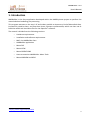
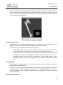
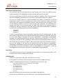
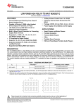
4. MAF: the NMSBuilder Core The Multimod Application Framework (MAF2) is an open source freely available framework for the rapid development of applications based on the Visualisation ToolKit3 and other specialised libraries. It provides high-‐level components that can be easily combined to develop a vertical application in different areas of scientific visualisation (see figure below). MAF has been further extended by an additional software layer, called MafMedical. MafMedical contains all MAF components that are specific to the biomedical application domain. A generic MAFMedical application, such as NMSBuilder, is defined by choosing from the framework the necessary components, and eventually specialising them. It is also possible to develop ad hoc components that are necessary only to the application itself, and plug additional 3rd parties libraries. There are four types of components that form any MAF application: Virtual Medical Entities (VMEs), which are the data objects; Views, that provide interactive visualisation of the VMEs; Operations, that create new VMEs or modify existing ones; and the Interface Elements, generic GUI components that define the user interface of the application. Special Operations are the Importers that let you import and convert into VME almost any biomedical dataset, and the Exporters that can convert the VME into files formatted according to the most common standards. 4.1. VME It provides the data Representation. Examples of VME are surfaces of muscle imported and segmented from DICOM images. A VME represents a data entity. VMEs are organised in a hierarchical tree (VME Tree or data tree) and they are all composed by a time-‐varying dataset, a time-‐varying matrix that defines the pose 2
3
http://www.openmaf.org http://www.vtk.org 7 NMSBuilder v.2.0
User’s Manual
of the VME with respect to its parent in the VME tree, and a set of metadata that provides all the textual attributes of the VME. 4.2. Views They allow the data Examination. There are various views that permit to analyse the Medical Data. A View provides an interactive representation of the VME Tree. For each view the system maintains a display list of the VMEs that must be rendered in that view, and a Compatibility list that specifies which types of VME can be rendered in a single instance, and which in multiple instances. The user can control certain properties and the behaviours of the view through the View Settings tab in the upper part of Control Bar. 4.3. Operations Operations create new VMEs or modify existing ones. At any time the user selects a VME and then chooses one of the available Operations. The Operation may accept only a particular type of VME, e.g. the Resample Volume Operation accepts only VMEVolumes. At any time, it is possible to run only those operations that accept the currently selected VME. Operations that need more than one input may request the additional VME to the user. The user can control certain properties and the behaviours of the operation through the Control Bar. Operations are modal: when an operation is running, it is not possible to run another operation and it is not possible to change the selected VME. Operations support the Undo/Redo feature. 4.4. Interaction and Interface Elements MAF framework supports the interaction within MAF applications. The features provided by this library include: ⋅
User re-‐configurable list of input and output devices to be used for interacting with the application. ⋅
Assignment of available devices for different "actions" to be performed inside the application. ⋅
Dynamic reconfiguration of the device assignment, on the basis of the current application state (running operation or application logic state). ⋅
I/O semantic abstraction layer, represented by "interactors" objects. Many off the shelf interactors for 2D and up to 6D interaction with 3D objects, support for haptic interaction (by means of the OpenHaptic extension library). 8 NMSBuilder v.2.0
User’s Manual
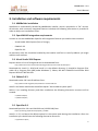
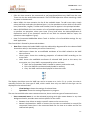
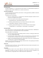
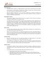
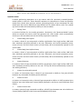
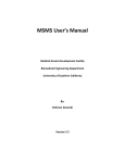
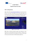
4.5. Integration with OpenSim APIs and specialised components In order to integrate the OpenSim APIs4 into the NMSBuilder application, a number of components were identified to be developed as specialisation of MAF basic features (VMEs, Views, and Operations). The scheme below presents the integration approach for MAF and OpenSim. Schematic representation of the components involved in the MAF-‐OpenSim integration. In black the components specialised from MAF and in red the communication flow. In particular, on the left side of the image the general components of the MAF framework (described in the previous sections) are presented, while on the right side the components of OpenSim involved in the integration are listed. In the central part of the scheme we represented the specialised components (that have been developed during the NMS Physiome project5) to achieve the integration. They consist in: -‐ a new VME type: which represents a general OpenSim model (C++ commands of the API) to be used as a template for the construction on the patient-‐specific OpenSim model and simulation; -‐ three specialised operations to edit the template model, define the simulation to be run, and compile the C++ commands of the API to generate the OpenSim model; -‐ specialised views for the post-‐processing and visualisation of the simulation results. The red arrows represent the flow of information among the modules. In summary, NMSBuilder provides a model template, which can be edited to include the patient specific information provided by the data in the NMSBuilder data tree. The model is composed by commands from the OpenSim API in C++. When completed, a specialised operation run the model by calling a compiler which generates the .osim model file to be then opened into the OpenSim user interface, or launch the OpenSim simulation which calls directly the SimBody Engine. The results can be then loaded back into NMSBuilder, which will provide specialised visualisation tools. 4
5
https://simtk.org/api_docs/opensim/api_docs/ http://www.nms-‐physiome.eu/ 9 NMSBuilder v.2.0
User’s Manual
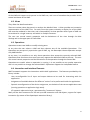
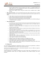
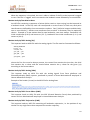
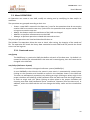
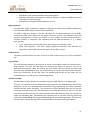
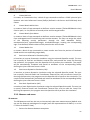
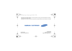
5. NMSBuilder application When launched the application interface looks like: In all visualisation windows the user can interact with the objects with the mouse in this way: • The left mouse button to rotate, • The central mouse button (or press down the scroll wheel) to translate/pan, • The right mouse button to zoom in/out. If a Laptop is used, please see in the computer manual on how to simulate the central button of the mouse from keyboard. There is a basic structure for any MAF application: it comprehends a well-‐defined GUI environment composed by a main Working Area, a lateral Control Bar showing the VME hierarchical structure, a Log Bar for the system messages, and the main menu (Menu Bar) with at least five items: •
Menu FILE: this item contains all the commands related to input/output operations; in the application skeleton the basic features are open/save/new commands to respectively load, store, or initialise a new msf (MAF Storage Format) session file. 10 NMSBuilder v.2.0
User’s Manual
•
Edit: this item contains the commands to cut/copy/paste/delete any VME from the tree. There are also the undo/redo commands. The Find VME operation allows searching a VME by name in the data tree. •
Menu VIEW: this item contains the list of the available views. To add a new view, simply select Add View and select the desired view. It is also possible to select which of the other bars (Control Bar, Log Bar, Tool Bar and Time Bar) have to appear in the principal window. •
Menu OPERATIONS: this item contains a list of available operations within the application; to perform an operation, select your input (if any) and select the desired Operation in Operations menu (if an operation cannot be run with the selected VME as input, the operation name appears in grey). •
How To Customize NMSBuilder Menu Tools: it defines a list of available settings for any MAF application. The Control Bar is formed by three sub-‐windows: •
Data Tree: shows the loaded VMEs with the relationship degree and for the selected VME three other tabs (in the bottom part of the Control bar): • VME output: shows the un-‐modifiable attributes of the VME related to the VME data structure. • Visual props: shows the rendering properties of selected VME according to the active view. • VME: shows the modifiable attributes of selected VME (such as the name, the encryption, etc.). Any VME is represented by colour and icon: § Blue: the correspondent VME is loaded in memory and can be used, § Pink: the VME has not been already loaded in memory, § Grey: the VME could not be displayed in the active view. The display check box near the VME icon can be a square or a circle. If it is a circle, the view is mutually exclusive for that type of VME, which means that only one VME of that type can be displayed in the selected view. •
•
View Settings: shows the settings of selected view. Operation: shows the setting of operation in progress. The user has available also some contextual menus; there are three types of contextual menu: •
View contextual menu: it can be activated pressing with right mouse button in any view background and it provides some actions specific for the views: • Rename view: allows to assign a specific name to the current view; • Normal size/maximize: allows to restore the size view to maximised or normal (for compound views there is the command both for the view as a whole and for the selected sub panel); 11 NMSBuilder v.2.0
User’s Manual
• Save as image: allows to save the content of the view in a standard image format (bmp, jpg, tiff, etc.); for compound views there is the command for the view as a whole or for the selected sub panel; • Export Scene (VRML): allows saving the content of the rendered view in VRML format. •
VME contextual menu: it can be activated pressing with right mouse button on any VME displayed in any view and it adds to the previous actions some others specific for the VMEs: •
•
•
•
•
Hide: allows to remove from the display list the selected VME; Delete: allows to delete from the Data Tree the selected VME; Move: launches the Move operation on the selected VME. Visual props: it opens a GUI exposing the visual properties of the VME according to the selected View or sub-‐panel. Tree contextual menu: • Save MSF layout: saves the layout of the current views with their display list into the msf; at the next opening of the msf it will be asked to the user if he/she wants to load also the corresponding layout; • Hide/show: it is present if the VME can be displayed in the active view and it allows to hide or show the VME; • Show sub-‐tree: it is present if a view is opened and it allows to display in the current view all the VMEs of a sub-‐tree; • Show same type: it is present if the selected VME can be displayed in the active view and it allows to display in the current view all the VMEs of the same type of the selected one present into the data tree; • Hide sub-‐tree: it allows to remove from visualisation in the active view all the VMEs of the sub-‐tree; • Hide same type: it allows to remove from visualisation in the current view all the VMEs of the same type of the selected one; • Crypt: applies encryption to the selected VME; • Enable crypt sub-‐tree: applies encryption to all VMEs of a sub-‐tree. • Disable crypt sub-‐tree: removes encryption from all VMEs of a sub-‐tree. • Sort children nodes: allows to sort children nodes in alphabetical order. • Keep tree nodes sorted: allows keeping the alphabetical sorting even when new VMEs are added to the data tree. 5.1. Menu FILE This menu allows managing the input/output of data to and from the application in different formats. The NMSBuilder files are stored in the internal msf format. Apart from the usual open, save, save as, close and quit operation, there are different importers and exporters for different data types. Importers/Exporters are grouped according to the type of data they are dealing with. In the current application version they are: Images, Geometries, Other, Motion Analysis, and Finite Element. 12 NMSBuilder v.2.0
User’s Manual
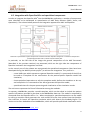
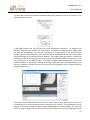
5.1.1. Importers Images/DICOM This importer loads medical images stored in DICOM format, and creates as output either a Volume, Mesh, or Image VME. The user has first to select from a standard window for folder selection the directory in which the DICOM files are stored. Once performed the folder selection, a new wizard window appears in which the user can subsequently: 1) see the images preview (with some options to interact: choose the number of study id if multiple ones are present in the folder and slide across the slices (or the time stamps if a time-‐varying dataset is being imported) with appropriate sliders, and perform windowing on the images); 2) proceed to the optional "Crop" stage, in which cropping is performed in the slices' plane by drawing with the mouse the crop area, and in the direction orthogonal to the slices by moving the "z-‐crop" slider. The in plane crop area can be changed by moving each side of the area and controlled over the different slices with the slice num. slider; 3) proceeding to the "Build" stage, only the cropped area is kept. The user can review the selected and cropped images, and choose among "Volume", "Mesh", and "Image" type, the type of VME resulting from the import, before completing the process by clicking "Finish". Images/Raw Volume This importer can load a raw binary volume file. A VMEVolume is created in the data tree. The user should choose the file name (browsing with the open button), should specify the endianity, the scalar type (char, short, int, float, double), the number of components (e.g. 3 in a RGB Volume) and specify if signed or not in the check-‐box. The user should also provide the dataset dimensions (number of pixels) and the spacing in mm/pixel in all directions. The import can be limited to a part of the whole, defining a volume of interest (VOI) through specifying the x, y and z pixel intervals to be considered (VOI x, VOI y, VOI z fields). If the spacing along Z is not uniform the user can specify a text file from which the Z-‐coordinates are 13 NMSBuilder v.2.0
User’s Manual
read (browsing with z-‐coord load button). The Z coordinates file should be a text file whose format is the following (the coordinates should be written in ascending order): Z coordinates: -‐109.1 -‐107.8 -‐106.5 -‐105.2 -‐103.9 Moreover, the user can set the header size to be skipped in the import process. The guess button makes the system to automatically evaluate the header size from the dataset dimensions inserted and the file size. Analogously to the DICOM importer, the user should define a memory limit beyond which the raw images will be stored as a VMEVolumeLarge. Finally, a VMEVolume (or a VMEVolumeLarge) is created in the tree upon pressing the ok button. Images/Images This importer can handle images in several standard imaging formats (jpg, png, bmp). A VMEImage is created in the data tree. Images/Raw Images This importer can load a stack of raw binary images and automatically creates a VMEVolume. The raw images should be stored in a single directory and should be named with the same prefix and a progressive number (e.g. RawImage_0006.raw, RawImage_0007.raw, etc.). The user should choose the name of single files in the folder through the prefix (e.g. RawImage_), the pattern (e.g. %s%04d) and the extension of the files (e.g. .raw). The user should also specify if the images are 8bits, 16 bits Little Endian, 16 bits Big Endian, 24 bits RGB, and whether they are signed or not. In case of 24 bits images also the presence of interleaving should be specified. The user should then set the overall dimensions of the volume in pixels and the spacing along the axes in mm/pixel. Ticking on a checkbox, a ROI can optionally be specified on the xy plane, drawing and adjusting a red box with left mouse button, whose real time dimensions are reported below. If the spacing of the images is non-‐uniform in the Z direction, the user can import a text file with the Z coordinates as in the Import Raw Volume. Moreover, the user can set the header size to be skipped in the import. In the file offset field the user can set an offset for the first slice number (e.g. 6) and in the file spc can set a spacing in the numbering of the images if different from unity. If the information provided are compatible with the files, a preview of the images appears in the window and the slices can be seen using the slice num. slider. Analogously to the DICOM importer, the user should define a memory limit beyond which the raw images will be stored as a VMEVolumeLarge. Finally, a VMEVolume (or a VMEVolumeLarge) is created in the tree upon pressing the ok button. Geometries/STL It loads a Stereo Lithography File, which contains a polygonal surface model. A VMESurface is created in the data tree. 14 NMSBuilder v.2.0
User’s Manual
Geometries/VTP It loads a 3D geometry in a .vtp file format, which contains a VTK XML-‐based description of a polygonal surface model. A VMESurface is created in the data tree. Geometries/INP/INP_AF It imports geometries from INP files. INP format is usually generated by AMIRA to describe geometries (triangle meshes). The INP format is the following: 1. Each line starting with # is a comment line; the future description assumes that all comments are skipped by the importer. 2. The first line contains three numbers separated by spaces: <NumberOfVertices> <NumberOfTriangles> 0 0 0 3. The following <NumberOfVertices> lines contain information about vertices: <VertexIndex> <XPosition> <YPosition> <ZPosition> 4. The following <NumberOfTriangles> lines contain information about triangles: <TriangleIndex> 0 tri <VertexIndex1> <VertexIndex2> <VertexIndex3> Geometries/MTR Files in MTR format are usually generated by FARO arm during measurements. NMSBuilder is able to import groups, containing landmark clouds from MTR files. Format description is the following: 1. First line contains names of the following columns, usually it is looking like Index Xmm Ymm Zmm A(deg) B(deg) C(deg); 2. Each following line contains landmark index in cloud and 6 values recorded from FARO. Currently only first coordinates are used, they are specifying landmark position; 3. Indexes in lines define grouping of points: when index in current line is not greater than in previous one, it means that new group begins. Importer is generating a VME group, containing Landmark clouds. Point grouping into clouds is based on grouping present in the MTR file. Other/VTK It loads data stored in vtk format. The type of VME created into the data tree depends on the information contained into the vtk file. Other/MSF It is possible to import in the current VME tree a MSF session file previously created with NMSBuilder. The data tree saved in the MSF file, the user wants to load, is imported in the current VME tree, and grouped under a VME Group called "imported from ". 15 NMSBuilder v.2.0
User’s Manual
Other/External data It loads a general file into the data tree (such as doc, xls, etc). When the msf is saved, the imported file is stored in the folder of the msf file. A VME is created which consists of a label that can be selected and opened with Open With External Program, if an appropriate application is properly installed on the user's computer for the specified type of file. In this case the standard application associated to the file extension is used to open the VME. Other/Matlab The operation allows importing a binary data container in the Matlab file format (i.e. a mat-‐
file), storing data representing a landmark cloud or a surface. Once imported, the file is added to the data tree as Surface VME or Landmark Cloud VME. •
Landmark Cloud file It must contain two matrices: the first [nx3] representing the coordinates of the n data points saved as 'filename_DataPoints', the second [4x4] representing the pose matrix of the cloud saved as 'filename_PoseMatrix'. Example: A mat-‐file named 'Landmarks.mat' representing a landmark cloud with n points must contain -‐ Landmarks_DataPoints [nx3] -‐ Landmarks_PoseMatrix [4x4] •
Surface file It must contain three matrices: the first [mx3] representing the coordinates of the m data points of the surface saved as 'filename_DataPoints', the second [kx3] representing the k faces (i.e. connections between vertices) of the triangularized surface saved as 'filename_Faces', the third [4x4] representing the global pose matrix of the surface saved as 'filename_PoseMatrix'. Example: A mat-‐file named Femur.mat representing a surface with m points and k faces must contain -‐ Femur_DataPoints [mx3] -‐ Femur_Faces [kx3] -‐ Femur_PoseMatrix [4x4] Motion Analysis/C3D-‐BTK It is able to read the following formats (Vicon Workstation© users refer to “User Preferences” in File menu): •
C3D data save format: Integer and Real •
C3D real data format: PC, DEC and MIPS •
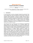
C3D analogue format: Unsigned and Signed In the Control Bar the user can select the various parameters that wants to import into NMSBuilder. 16 NMSBuilder v.2.0
User’s Manual
It is possible to import: •
Trajectories: it will create a landmark cloud containing all the landmark saved in the c3d file; •
Analogue Data as signals from force platforms and ElectroMyoGraphy systems; •
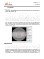
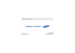
Force Plate Data as platform surface, Centre Of Pressure (COP), Ground Reaction Force (GRF) and Moments to the platform centre. Example after the import of a common C3D file (i.e. cnBC10b02.c3d) Also, a dictionary saved in the disk in an ASCII file can be specified to group the landmarks trajectories in different groups. The format of the dictionary is: LAND1 CLOUD1 LAND2 CLOUD2 … LANDn CLOUDn Where in the first column it is specified the landmark name and in the second column it is specified the cloud name. If no dictionary is input the landmarks trajectories will be loaded in a single landmark cloud (e.g. the group cnBC1b02_TRAJECTORIES in the second image above). Motion Analysis/Landmark The user is able to import a landmark cloud from an ASCII file. The imported landmarks are stored in the data tree in a VMElandmark cloud with the same name of the imported file. The imported file can represent a landmark cloud that is: •
Time-‐varying: the first row indicates the TimeStamp, the following rows contain the landmark name and the landmark coordinates at the given timestamp; •
Static: each row contains only the landmark coordinates. 17 NMSBuilder v.2.0
User’s Manual
When the operation is launched, the user is able to indicate if the file to be imported is tagged or not. If the file is "tagged" each row contains the landmark name followed by its coordinates. Motion Analysis/Raw Motion Data An ASCII file containing a sequence of points (either static or time-‐varying) can be imported as a landmark cloud. In the file, each row corresponds to a time frame. In each row, each point coordinates are defined by three consecutive numbers. Dot (.) delimits integers and decimals, one or more blanks ( ) delimits one coordinate from another. A dictionary may be optionally chosen. Example of a raw motion data for two landmarks, two time stamps. Landmark1 has initial coordinates (0 0 0) and moves to (2 2 2), Landmark2 has initial coordinates (1 1 1) and moves to (4 4 4). Motion Analysis/ASCII Analog (X,Y) This importer loads an ASCII file with the analog signals. The file must be formatted as follows: VPH2_ANALOG
t:t1,t2,...,tn
x:x1,x2,...xm y11,y12,...,y1n y21,y22,....,y2n ... ym1,ym2,...,ymn where the first line must be always present, the second line contains the time bar, the third line contains the x values and the matrix below contains the y values for the given (t,x) according to the format above. Motion Analysis/ASCII Analog (VWs) This importer loads an ASCII file with the analog signals from force platforms and ElectroMyoGraphy (EMG) systems, produced by means of Vicon Workstation© employed in Human Movement Analysis. Example of the header (4 rows) in the ASCII file for Analog Data. Motion Analysis/ASCII Forces Plates (VWS) This importer loads an ASCII file with the GRF (Ground Reaction Force) data produced by means of Vicon Workstation© employed in Human Movement Analysis. Motion Analysis/ASCII Trajectories (VWS) This importer loads an ASCII file containing all landmarks trajectories, i.e. the position of any marker for any single frame that composes the marker trajectory. 18 NMSBuilder v.2.0
User’s Manual
Particularly, this file is produced by means of Vicon Workstation© (www.vicon.com) employed in Human Movement Analysis. Example of the header (4 rows) in the ASCII file for landmark trajectories Finite Element/Generic mesh This importer allows the creation of a VMEmesh from an Ansys Text file. The user selects two text files, one for the nodes and other for the elements. Eventually the user can select a file with the material properties. The file defining the list of nodes should be a matrix, where: •
•
The first column indicates the node number Columns from second to fourth define the x,y,z, nodal coordinates. The file defining the list of elements and the connectivity should be a matrix, where: •
•
The first column indicates the ID of the element Columns from the second to the sixth indicate some properties that respectively define "associated material, element type, associated set of constants, element refsys, section properties". These columns are present because Ansys was taken at first instance as a reference program and this is how Ansys handles element properties. At the moment these columns have to be included also when creating a mesh from scratch and not deriving it from Ansys. However, they represent a quite straightforward way to group elements in certain subsets. The second column, in particular, can be very useful since it indicates which "material" the element is made of. This becomes meaningful if the user specifies also a "materials file" when importing. The optional file defining the list of materials should be formatted as follows: MATERIAL NUMBER = 1 EX = 20932. NUXY = 0.30000 DENS = 1.2508 MATERIAL NUMBER = 2 EX = 18456. NUXY = 0.33000 DENS = 1.1476 .......etc..... Each element having a "1" in the second column of the file defining the list of elements will be assigned properties of material number 1, and so on. Note: additional rows, defining more properties can be added (e.g. MU = 0.54000 to define a frictional coefficient). Once a mesh has been imported, the number of the "material card" as well as the material properties of each element can be visualised using the "visual props" panel (or right-‐clicking on the VME in the 19 NMSBuilder v.2.0
User’s Manual
compound views), by selecting "enable scalar field mapping" and browsing the desired field to be visualised among those available. Finite Element/Ansys Input file This importer creates a VMEmesh directly from an Ansys ASCII input file. The importer currently supports only the following entities: nodes, linear and quadratic solid elements (2D elements can be created as degenerated solid elements), and material cards. Finite Element/Ansys CDB file This importer creates a VMEmesh directly from an Ansys ASCII archive (.cdb file) which can be written directly by the Ansys program. The importer currently supports only the following entities: nodes, linear and quadratic solid elements, and material cards. OpenSim/ Inverse Kinematics simulation results It imports output file (*.mot) generated by Inverse Kinematics simulation in OpenSim. The values of the generalized coordinates will be automatically stored as vtk data ASCII format in the corresponding joint frame in child having the same name of the generalized coordinate. OpenSim/ Inverse Dynamics simulation results It imports output file (*.sto) generated by Inverse Dynamics simulation in OpenSim. The values of the joint moments will be automatically stored as vtk data ASCII format in the corresponding VME joint frame in child having the same name of the generalized coordinate. 5.1.2. Exporters All geometric format exporters (STL, INP, MTR), the VTK exporter, and the Ansys Input File exporter expose the “apply absolute matrix” option. This option let the user export the VME applying the current absolute pose matrix (that describes the position of the VME with respect to the global reference system) to the original data contained in the dataset. Images/Raw It stores a VMEVolume in raw binary format (both as single binary file or stack of binary images). 20 NMSBuilder v.2.0
User’s Manual
Images/BMP It stores a VMEVolume in a set of bmp files. Files can be saved in RGB or Grayscale format. It is also possible to set an offset different from zero for the first bmp file. Progressive numeration is used for the other image files. Geometries/STL It stores a VMESurface in STL format (both binary and ASCII). Geometries/INP Exporter operation for the INP format described in the importers section. Geometries/MTR It is exporting single landmark cloud (in case input node has Landmark cloud type) or all children of input node having Landmark cloud type (in the other case). MTR file, that contains data for one or several landmarks, is generated as result. Other/Matlab This operation allows exporting Surface VMEs and Landmark Cloud VMEs as binary data containers in the Matlab file format (i.e. a mat-‐file). Once exported, the mat-‐file can be loaded into the Matlab workspace. •
Landmark Cloud file It is exported as 'filename.mat' and contains two matrices: the first [nx3] representing the coordinates of the n data points as 'filename_DataPoints', the second [4x4] representing the pose matrix of the cloud as 'filename_PoseMatrix'. •
Surface file It is exported as 'filename.mat' and contains three matrices: the first [mx3] representing the coordinates of the m data points of the surface as 'filename_DataPoints', the second [kx3] representing the k faces (i.e. connections between vertices) of the triangularized surface as 'filename_Faces', the third [4x4] representing the global pose matrix of the surface as 'filename_PoseMatrix'. Other/VTK It stores a VMESurface or a VMEVolume in vtk format. Other/Action Line It exports a txt file of the action line information. The first rows of the txt file contain the name of the action line, the second row the data headers. Data contain the timestamps and the trajectories of all points that define the action line. Other/Meter It exports a txt file of the meter information. The first row contains the timestamp while the other rows contain the information of the meters group selected for the export operation. 21 NMSBuilder v.2.0
User’s Manual
Each meter is characterised by a set of 9 rows where the first row contains the meter name and the other 8 rows are as follow: one row named "Origin" followed by 3 rows containing the coordinates (x,y,z) of the meter starting point and a row named "Insertion" followed by other 3 rows containing the coordinates (x,y,z) of the meter ending point. Motion Analysis/Landmark It stores a VMELandmarkCloud in ASCII file. The output format is structured in blocks where the first row correspond to the time frame and the rows below contains the location of each landmark for the given time frame. For each landmark it is given in sequence the label and the x,y and z locations. An example of the output format is reported here below: Time 0 C7 0 RA 0 … LS4 0 Time 1 C7 0 RA 0 … LS4 0 Time 2 C7 0 RA 0 … etc … 0 0 0 0 0 0 0 0 0 0 0 0 0 0 0 0 0 0 0 0 0 0 Finite Element/Ansys Input File This exporter creates an ASCII input file (.inp) that can be directly read by Ansys program. The exporter can deal with the basic finite element entities supported by the NMSBuilder application: nodes, linear and quadratic solid elements, and material cards usually containing Young's modulus, density, and Poisson's ratio values. In the exported file, elements are grouped according to either element type and material properties. Finite Element/Generic Mesh This exporter allows the creation of three separate files, one containing the nodes coordinates, one containing the elements description and the other containing the material cards. The node file contains a matrix, where: •
The first column indicates the node number •
Columns from second to fourth define the x,y,z, nodal coordinates. The file defining the list of elements and the connectivity contains a matrix where: •
The first column indicates the ID of the element •
Columns from the second to the sixth indicate some properties that respectively define "associated material, element type, associated set of constants, element refsys, section properties". 22 NMSBuilder v.2.0
User’s Manual
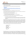
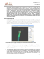
The last 4 columns contain the element properties according to the ANSYS standards. Particularly, the second column indicates the "material" cards contained in the "materials file". This file contains the list of materials in the following format: MATERIAL NUMBER = 1 EX = 20932. NUXY = 0.30000 DENS = 1.2508 MATERIAL NUMBER = 2 EX = 18456. NUXY = 0.33000 DENS = 1.1476 .......etc..... Note: additional rows, defining more properties can be found (e.g. MU = 0.54000 defining the frictional coefficient). 5.2. Menu VIEW Every VME can be analysed and managed through a combination of views and operations. Many instances of the same view with different VMEs displayed and/or different views can be opened at the same time according to the user’s needs. The views available in the current release of NMSBuilder are described further on. 5.2.1. Arbitrary The Arbitrary View is a compound view made of two panels. In the left panel, the user can change using gizmos the position and the orientation of an arbitrary plane; in the right panel the corresponding volume section is showed in a 2D parallel view. 23 NMSBuilder v.2.0
User’s Manual
The view properties can be changed from the View Settings panel, where the user can change the slice visualised in two ways: •
Gizmo Interaction: It is possible to translate or rotate the slice with three arrows (for the translation) or three rings (for the rotations). By selecting the desired gizmo and holding pressed the left button of mouse, the gizmo moves and the plane is updated accordingly. •
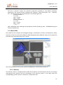
Text Interaction: The user can write the value in the corresponding text box. The user can also change the LUT of the VMEVolume and with the reset button restore the initial plane position. 5.2.2. DRR The DRR View is a special volume renderer window that displays a VMEVolume as the result of a digitally reconstructed radiography (DRR) algorithm, while a VMESurface is rendered with a 3D representation. In the visual props panel, the DRR settings can be used to change the generated DRR (e.g.. colour, or the level of the project with the gamma value). The camera settings can be used to modify the position of the projection instead of using the mouse interaction. 24 NMSBuilder v.2.0
User’s Manual
5.2.3. Analog Graph The view called Analog Graph shows the scalar value of the analog signals (i.e. EMG signals of the muscle electric activity). The user can select one or more signals among those imported. It is possible to visualise one or more signals in different windows. In order to plot a signal, this must be selected in the visual props tab and the Plot button must be used. The signal name can be modified and visualized by flagging the button Legend and each signal can be assigned a specific Colour. The user can also modify the axes range deselecting the Autofit plot checkbox and then defining into the text boxes the axes ranges. X Title and Y Title text boxes allow assigning user defined label to the axes. 5.2.4. Global Slice The Global Slice View shows a slice obtained from the intersection of one or more volumes with a user selectable coordinate plane. In the View Settings it is possible to choose the orientation of the plane with respect to the coordinate system, select the position of the plane in the chosen direction, change the transparency with the opacity slider or the LUT of the selected volume. An indication of the slicing plane position (origin and director cosines) is reported in the bottom left corner of the view. 5.2.5. Isosurface In the View Isosurface a VMEVolume is displayed as a surface extracted with an iso-‐density contour filter. The user can interactively change the density threshold (contour) and the transparency threshold (alpha) in the visual props panel. 25 NMSBuilder v.2.0
User’s Manual
5.2.6. OrthoSlice The OrthoSlice View is a compound view made of four panels and three gizmos. A perspective panel shows a volume intersected by the three orthogonal planes and the other three panels show a parallel view of each other slice. As for the RXCT view, a VMESurface is represented with a 3D rendering in the perspective panel and as contours in the other three. The user can modify the LookUpTable for displaying the VMEVolume. When the Snap on checkbox is activated the slices are blocked to move on the slices of original CT dataset. When this checkbox is deactivated, the user can see slices created with the interpolation technique. The border slider also activates when a surface is selected and it allows setting the thickness of the contour representing the surface into the slices panels. 26 NMSBuilder v.2.0
User’s Manual
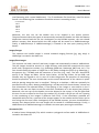
5.2.7. RXCT The RXCT View is a compound view made of eight panels and six gizmos. A gizmo is a particular handle that is instantiated by a View or an Operation to allow direct interaction with the mouse. A VMEVolume is displayed in this View as a digitally reconstructed radiograph on the Anterior/Posterior plane and on the Medial/Lateral plane. The other six panels show six CT slices that can be moved arbitrarily using the six gizmos. If a VMESurface is displayed in the same window it will appear as a 3D surface in the projection panel and as the contour coming out from the section in the slices. In the RXCT view the View settings panel reports the properties of the view. It is possible to choose the side to view for the medio-‐lateral projection and to move all slices at the same time. When the Snap on checkbox is activated the slices are forced to move on the slices of original CT dataset. When this checkbox is deactivated, the user can see the slices created with the interpolation technique. The move all checkbox allows to move all slices together. The adjust slices button activates when a VMESurface is selected and it allows to automatically set all the six slices within the surface bounding box. The border slider also activates when a surface is selected and it allows setting the thickness of the contour representing the surface into the slices panels. 5.2.8. Slicer The Slicer View is a compound view made of two panels: the left one is a perspective one, while the right one is a 2D parallel view. When a VME slicer is displayed in this view, in the right panel the section of the slicer is visualised and all other VMEs into the view are sliced in correspondence of the slicer. The slicer can be moved using the standard Move operation. 5.2.9. Surface The Surface View displays VMESurfaces and landmarks in a three-‐dimensional perspective render window. VMEVolumes are displayed only with their bounding box. 27 NMSBuilder v.2.0
User’s Manual
The control bar tabs for this view and for a VMESurface are: •
Visual Props: o
Display List: This checkbox allows to speed up the rendering of VMESurface. o
Scalar Vis.: The user can visualise with different colours possible scalar values associated to the VMESurface. o
Norm Vis.: The user can visualise the normal to the cells on the VMESurface. o
Edge Vis.: The user can visualise the surface free edges (i.e. border of a hole). The edge is visualised with a colour complementary to that of the surface. o
Property: This checkbox applies the Material properties to the VMESurface: §
Material: Opens a window for creating or modifying the visualisation properties of the VMESurface. The user can choose among several pre-‐
defined materials that have different rendering characteristics, or define a new one. The user can specify the colour and intensity of the ambient, diffuse, and specular setting. A preview is shown on the top of the window. In addition the user can set a transparency level (opacity) and the wire frame representation. The new material can be saved with a custom name in the material library to recover it when necessary. §
LUT: The user can modify the LookUpTable for displaying the scalars associated to the VMESurface. §
LOD: This is a multiscale option. If activated, it modifies the visualisation of a VME in relationship with its dimensions with respect to the camera position (e.g. if a VME is zoomed in it becomes first transparent then it disappears, while it is zoomed out, below a certain dimensions the VME is substituted with a glyph). 28 NMSBuilder v.2.0
User’s Manual
•
View Settings: This tab shows the properties of the View. It is possible visualise the grid or the axes and modify their colours. The user can create new camera positions. The control bar tabs for this view and for a VMELandmarkCloud are a subset of those available for the VMESurface, namely: o
Display List: This checkbox allows speeding up the rendering of VMELandmarkCloud. o
Scalar Vis.: The user can visualise with different colours possible scalar values associated to the VMELandmarkCloud. o
Material: Opens a window for creating or modifying the visualisation properties of the VMELandmarkCloud, with the same options described above for VMESurface and shown below In the Surface view, it is possible to visualize the Landmark trajectories. The user must set the interval that you wants visualise (default = 0) in the visual props of a single landmark. In the Surface view, it is possible to visualise the Ground Reaction Force (GRF). The platforms and the vectors are visualized singularly. In the visual props tab of a single vector the user can select the visualisation of the vector arrow, the Centre Of Pressure (COP) and the Vectogram. 29 NMSBuilder v.2.0
User’s Manual
5.3. Menu OPERATIONS An Operation can create a new VME, modify an existing one by modifying its data and/or its attributes. The operations are grouped according to their aim: •
•
•
•
Create: a new VME is created in the data tree; i) new for the operations that do not require another VME to create the new one; ii) derive for the operations that require another VME as input to create the new one. Modify: the dataset and/or the attributes of the VME are changed Measure: to perform measurements on the VME Manage: to perform operations related with external services The principal operations are listed and described further on. The Validate Tree operation allows the user to check, after saving, the integrity of the saved msf file. The operation will check the binary data associated to each VME and will provide the found errors into the log area. 5.3.1. Create sub-‐menu new/group The VMEGroup is a particular VME that defines a branch of the data tree. By default it is created as child of the selected VME in the tree and is named group, then the name can be changed in the VME tab. new/refsys (Reference System) It is possible to create an orthogonal reference system (VMERefSys). A new VMERefSys that inherits the parent’s pose matrix is automatically created when clicking on the operation and checked as normal in the checkbox shown in the VME tab. The user can subsequently reposition it by defining an origin (clicking on select origin in the proper checkbox and selecting a VME Landmark from the data tree with the Origin button) or both an origin and a XY plane (clicking on select plane in the proper checkbox and choosing two other VME Landmarks (Point 1 and Point 2 buttons) from the data tree). In addition, within the VME tab the user can change the RefSys name and the visualisation scale. 30 NMSBuilder v.2.0
User’s Manual
new/parametric surface It creates a Parametric Surface VME. This kind of VME is a run-‐time modifiable implicit surface. The user can choose the form of the new surface (sphere, cone, cylinder, cube and plane) and set the corresponding parameters. For example, if the user creates a sphere surface, the parameters to set are radius and the number of triangles that are generated by the curvature resolution. new/add landmark With this operation the user creates a VMELandmark Cloud (child of the VME selected when the operation is launched). The user can either choose a dictionary to firstly select a landmark name (using the load dictionary button then the list of available names appears in the upper side of the tab) or can assign a name to each landmark writing in the landmark name text box. The landmark is created either picking on the selected VME or directly writing the landmark coordinates in the Position text boxes. An example of dictionary is the file called dictionary.dic located in the subfolder NMSBuilder\Config\Dictionary. In this file the anatomical landmarks of the femur described in Kepple TM et al., "A three-‐dimensional musculoskeletal database for the lower extremities", J Biomech. 1998 Jan;31(1):77-‐80, can be found. Once created the landmark cloud, the user can add other landmarks by performing the Add landmark operation having selected the landmark cloud VME. To perform the last action, the landmark cloud has to be exploded. The user can change the cloud status using the Explode checkbox in the VME tab. In the VME tab, also the radius and the resolution of the landmarks may be changed. new/OpenSim Model The operation allows creating a cpp source code of an empty OpenSim model. It is possible to edit this source code using the Editing Tools facilities. new/OpenSim Model from wizard The operation allows creating the cpp source code of an OpenSim model definable by the user, through a step-‐by-‐step guided procedure from GUI. The source code will be automatically updated at each procedure step, and can be edited and compiled later using the Editing Tools facilities. 1. Create Bodies from Surfaces It adds rigid bodies to the model. It is possible to select single-‐surface or multi-‐surface bodies with their attributes previously defined in the tree. Geometric and inertial properties (mass, center of mass and 3x3 inertial tensor) of each body will be automatically passed to the source code. 2. Create Joints It adds joints to the model. Joint positions and orientations will be automatically passed to the source code. The range of generalized coordinates will be set by default to [-‐10 10] for 31 NMSBuilder v.2.0
User’s Manual
translational DOF and [-‐π π] for rotational DOF. Available types of joint (CustomJoint class), selectable from the drop-‐down menu, are: -‐
Free joint with ground: 6-‐DOF joint between a Parent Body and a Child Body. Further information to specify is Child Body. Ground will be used as Parent Body. -‐
Ball Joint: 3-‐DOF spherical joint between two Joint Reference Frames (RefSys) defined in the Parent and Child Body local frames. Further information to specify is Parent and Child Bodies and the two RefSys identifying the joint. -‐
Pin Joint: 1-‐DOF rotational joint between two Joint Reference Frames (RefSys) defined in the Parent and Child Body local frames. Further information to specify is Parent and Child Bodies and the two RefSys identifying the joint. The rotational axis will be the common z-‐axis (blue axis). -‐
Custom Joint: 6-‐DOF joint between two Joint Reference Frames (RefSys) defined in the Parent and Child Body local frames. Further information to specify is Parent and Child Bodies and the two RefSys identifying the joint. 3. Create Marker Sets It adds markers to bodies. It is possible to select the source landmark cloud, previously defined in the tree, and the corresponding target body. Marker positions and target bodies will be automatically passed to the source code. 4. Add muscles It adds muscle actuators (Thelen2003Muscle class) to the model. It is possible to select a Wrapped Action Line defining each muscle actuator. The user can assign the values of the following muscle parameters through the VME Metadata facility: maxIsometricForce, optimalFiberLength, tendonSlackLength, creating the corresponding tags. If not defined, default values will be assumed. Actuator paths (i.e. position of muscle points and target bodies) and muscle parameters will be automatically passed to the source code. derive/slicer When the user wants to create a customized slice of a VMEVolume, he/she can use a Slicer. When launched, the operation asks which VMEVolume has to be used for the slicing. For changing later on the volume to be sectioned, use the button Volume in VME tab. derive/freeze vme This operation allows the user to freeze a procedural VME by fixing once for all VME parameters, such as position and displayed dimension of a reference system, or the type and parameters of a parametric surface. The type of VME created from the operation depends on the input VME, i.e. a parametric surface gives as output a VME surface, a meter a polyline, etc. derive/distance meter The Distance Meter is a particular VME which takes as input two or three VMEs and gives as output the distance or the angles between them. 32 NMSBuilder v.2.0
User’s Manual
It is possible to measure a distance between two points, between a point and a line, or the angle between two lines. In the VME tab the user can find all the meter parameters definition. To measure the distance between two VMEs, the user selects line distance mode and the VMEs with the start and end buttons. To measure a distance of a point from a line (line distance mode), the user selects the point with the start button and defines the line with two VMEs selected through the end and 2nd point buttons. The angle (line angle mode) is measured between the two lines that origin at the start point and are defined by the other two. If the user moves one of the Meter origins, the meter updates itself automatically. If the plot profile checkbox is activated, a histogram dialog is opened. With the Probed button the user can selected a volume from the tree and see the histogram of the volume densities along the meter line. The meter can be visualized with a thin line or with a tube of user defined radius, that can be capped or not (visual props tab when a Surface view is active). The visualisation of the meter can be set to change the meter colour depending on its actual length. The user can define a range of length so that if the meter is shorter than the minimum length (that is its 33 NMSBuilder v.2.0
User’s Manual
initial length defined as follows) then its colour is set to blue, if it is longer than the maximum length (calculated as follows) its colour is set to red, and it is changed from blue to red in the range in between. The range can be defined directly typing in the values in the boxes, or calculating the values from the initial meter length. If the absolute mode is chosen, then the initial length of the meter (set by the user in the init field) is an absolute value expressed in the same units of the meter length (e.g. mm) and the delta% field sets the upper boundary of the range as a percentage of the initial length. If the relative mode is chosen, then the init field indicates the lengthening (always in mm for example) of the actual meter with respect to the initial one. The percentage field works in the same way as explained above. derive/wrapped action line The Wrapped Action Line is a particular VME which takes as input two VMEs as starting and ending points and gives as output the length of the curved path, plus the current position of a number of intermediate via-‐points, when present. If the user moves a VME, the meter updates itself automatically. The two groups of methods currently implemented are the "Geodesic method" and the "Pivot-‐set method" (see the image below). The Wrapped Action Line VME tab exposes the following parameters and sub-‐panels: •
•
•
Name: to assign the VME name in the data tree. Geodesic method: it computes an action line wrapping around one (sphere or cylinder) or two (sphere-‐cylinder) parametric surfaces. The method assumes that the action line lies on a plane and, among all planes containing the origin and insertion of the action line, the shortest one is chosen. Pivot-‐set method: it allows the user to define the action line through ploy-‐lines by defining a series of intermediate via-‐points (or by wrapping the action line around a parametric surface (sphere, cone, cylinder, cube, plane or an ellipsoid). This method assumes that the action line lies on the plane identified by the origin, the insertion and the origin of the parametric surface the action line is wrapping on. 34 NMSBuilder v.2.0
User’s Manual
The two panels expose the following parameters: The Geodesic method: •
o
o
o
o
o
Wrap: it defines the method used to compute the meter curved path. It can be set through a popup window as single_sphere, single_cylinder or sphere_cylinder. Start: it defines the landmark taken as starting point of the wrapping action line End: it defines the landmark taken as ending point of the wrapping action line PathNum: it defines the accuracy of the identification of the shortest geodesic path. Higher it is more accurate and slower is the computation of the shortest path. Sphere/cylinder: it defines the wrapping surface/s the algorithm uses to wrap the action line The Pivot-‐set method: •
•
Wrap: it defines the method used to compute the meter curved path. It can be set through a popup window as manual, automated or IOR_automated. Manual: additional inputs (intermediate points) are chosen from a list of the VMEs in the tree. The outputs are the sum distance of all point-‐to-‐point segments and the current locations of all VMEs composing the meter. o Automated: the additional input to define the meter path is a Parametric Surface to be used as wrapping surface. Outputs are the length of the meter curved path and the current locations of the two tangent points used to compute the overall distance. To predict wrapping, it is necessary that, assumed the origin as a light source, the insertion point lies in the parametric surface shadow. o IOR_automated: the additional input to define the meter path is a Parametric Surface to be used as wrapping surface. Outputs are the length of the meter curved path and the current locations of the two tangent points used to compute the overall distance. This method allows the action line to wrap around the parametric surface for up to 270°, depending on the orientation of the coordinate system of the parametric surface. o
•
Reverse direction checkbox: this option is active if the selected wrap method is automated. It switches the meter path from a side to the other of the parametric surface. •
MidPoints: this option is active if the selected wrap method is manual. The list of VMEs selected as meter mid-‐points appears in the window below. It is possible to add, remove, or modify the VMEs sequence using the Add, Remove, Up and Down buttons respectively. The visualisation of the meter is similar to that of the distance meter and changeable in the visual props tab. derive/muscle wrapper The Muscle Wrapper is a particular VME which takes as input the following VME's: 35 NMSBuilder v.2.0
User’s Manual
• Muscle surface: VME representing the muscle to be wrapped • Wrappers: wrapped action lines in the Rest Pose and the Current Pose • Origin and Insertion areas: single landmark or landmark cloud The operation gives as output a VME representing the deformed muscle surface based on the VME's defined in the rest and the current pose. The deformation is governed by the difference between the output from wrappers in the rest and the current pose. The information regarding the origin and insertion areas is used to compute the fibres direction. In the Muscle Wrapper 'VME tab' the user will find the following parameters: In the Muscle Wrapper VME tab the user will find the following parameters: • Name: to assign the VME name in the data tree • Operational Mode: specify the mode that will be used for the wrapping. o Simple: the input muscle VME at the time 0 is deformed according to the differences between outputs from wrappers at the time 0 and outputs at the current time o Advanced: the user needs to specify different wrappers (they may not change in time) for the rest and current pose • Use RS: if checked the deformation algorithm will use the origin of Reference System VME specified for wrappers whenever it is available • Generate fibres: if checked the outputs are muscle fibres instead of deformed muscle • Muscle Surface: Selects the VME to be wrapped • Wrappers: Shows the wrappers added in the next box • Add new wrappers: Selects VME's with the wrapper o RP, CP: Rest Pose, Current Pose 36 NMSBuilder v.2.0
User’s Manual
o RP RS, CP RS: [optional] selects a VME that serves as a coordinate system for deformation • Fibres options: defines the fibres settings o O: selects the VME representing the origin area (single landmark or landmark cloud) o I: selects the VME representing the insertion area (single landmark or landmark cloud) o Type: selects the geometry type of fibres through a popup window o Num: specifies the number of fibres to be created within the muscle volume o Res: specifies the resolution of the fibber o Thick: specifies the thickness of the fibber • Smooth fibres: if checked a smoothing process is applied on the generated fibres • Smoothing options: specifies the number of smoothing iterations in terms of steps and weight It is possible to show, checking the options, the template (the output is a set of fibres with a target cube), the fitting process and the fitting result. derive/extract isosurface With the Extract Isosurface operation the user can extract a VMESurface from a given VMEVolume by selecting an iso-‐density threshold. The user can change the threshold grey level to define the iso-‐density surface (called contour value). It is possible to navigate the volume to check the surface contour and to pick a new threshold value on the volume slice. The volume slice can be removed 37 NMSBuilder v.2.0
User’s Manual
from the visualisation (slice checkbox) or changed of position with the corresponding slice position slider. The optimize option (activated by default) automatically applies a filter to the surface before creating the VME in the data tree which deletes the closed surfaces internal to the extracted surface. derive/decompose time Decompose time is an operation which takes as input a time varying VME and gives as output a desired number of static VMEs following a user defined mode. The Decompose Time panel shows the following options: • Timestamps mode: The user specifies a list of timestamps. The operation creates a static VME freezing the input time varying VME at the specified time stamps. • Interval mode: The user specifies a time interval. The operation creates a static VME freezing the input time varying VME for all frames within a specified time interval. • Periodicity mode: The user specifies a periodicity. The operation creates a static VME freezing the input time varying VME at the periodicity indicated in the time bar. derive/AFRefsys This operation is designed to create anatomical reference systems for different segments, following ISB recommendations. Currently, it is using some hardcoded landmarks names for calculating reference system for lower limb bones and PNT1, PNT2, PNT3 landmarks for generating reference system for arbitrary segment. 6-‐DOF placement modification of final result is possible, using vme tab for RefSys VME. derive/average landmark 38 NMSBuilder v.2.0
User’s Manual
Operation is applicable to any landmark cloud. It appends to the cloud a new landmark, that has position (positions in case of animated cloud) averaged from positions of landmarks initially present into the cloud. derive/extract label Extract label can be launched when a Volume or a Labeled Volume is selected. It enables the user to identify portions of the volume that have a defined value or label and creates a VME Surface that includes these regions. In the operation tab the user can define the value or label name to extract, and select whether a smoothing has to be performed (default setting: off) on the resulting surface. In case the smooth checkbox is activated, the user is allowed to modify the parameters of the surface smoothing algorithm. 5.3.2. Modify sub-‐menu fuse/register landmark cloud The operation Register Landmarks Cloud allows the user to register a source Landmarks Cloud onto a target Landmarks Cloud by the Single Value Decomposition (SVD) method. This registration provides as output a new Landmark Cloud (if the apply registration matrix to landmarks option is not selected) generated from a rigid, affine and similar transformation that, applied to the source cloud, best fits the landmarks coordinates with respect to the target ones. The registration is performed by matching landmarks that have the same name in the two landmark clouds. This implies that the two landmark clouds must have a sub-‐set of landmarks with common names. This operation is enabled only if the two landmark clouds are collapsed (see Add Landmark to know how to explode/collapse a cloud). It is possible to make spatial registration with three different types of registration: rigid, similarity, or affine (with the reg. type box). Moreover, it is possible to carry out registration for a single or more frames. In the last case, the user must flag the option multi-‐time. The follower surface button allows to select a VME surface that will get applied the same transformation of the registered cloud. The weighted registration button allows assigning weights to the landmarks to be used in calculating the registration. 39 NMSBuilder v.2.0
User’s Manual
fuse/reparent to The VME absolute position in a MAF application is given by the concatenation of the VMEs pose matrices in a given branch of a data tree. If a VME is moved from a branch to another one in the hierarchy, its absolute position can change. With the Reparent Operation a user can move a VME from a branch to another one without changing its absolute pose. When launched the operation opens a window to select the VME to be reparented to. fuse/register surfaces The operation Register Surface allows the user to register a source surface or landmark cloud onto a target surface or landmark cloud. The operation uses the ICP (Iterative Closest Point) technique for surface registration. The registration operation output is a new VME generated from an affine transformation that, if applied to the source VME, makes the points of the source fit the target ones. If the source or target is a landmark cloud, this operation is enabled only if the two landmark clouds are collapsed. The user can set the iteration number of the algorithm (in conv. step inside the operation tab). filter surface The Filter Surface operation takes as input a VME Surface and applies to it a combination of vtk surface filters (smooth, decimation, etc.). When the user applies a filter to a surface the program alerts that a new VME Surface (if you try to act on an imported surface) will be created. The user can use many type of filters and set the parameters for each one. For example, with the smooth filter it is possible to define the iterations number. volume density With this operation the user can modify the density of a VME volume (i.e. the scalar attribute, e.g. Hounsfield Units in volumes derived from a CT scan) The modification is applied over a volume of interest specified by a surface (VOI surface). The user is asked to choose a VME surface from the tree that defines the volume of interest, and the scalar value with which the VOI will be filled. deform surface The operation "Deform surface" deforms the surfaces accordingly to differences between two polylines and a chosen deformation method. It takes as input a VME surface and two polylines. The operation opens a pop-‐up window where the GUI allows the user to: • Automatically create a base curve to deform • Selecting from the three two curves (the original curve and the deformed curve) • Edit both the original and the deformed cure by adding, moving, deleting and other editing options on curve points 40 NMSBuilder v.2.0
User’s Manual
• Sow/Hide in the preview window curves and surfaces • Selecting alternative deformation methods (Blanco's method, Modified Blanco's method and simple warping) • Saving both the original and the deformed curve apply trajectory The operation "Apply Trajectories" applies a trajectory to a static (only) VME by loading the instantaneous VME's poses from an external ASCII file. The VME's trajectory, written in the file, describes the instantaneous pose of the VME's coordinate system with respect to the global reference system. The trajectory input file must be formatted as a matrix nx7 where n is the number of time stamps and the 7 columns contains, in sequence, the timestamp and the pose parameters: x, y, z, alpha, beta, gamma. • x,y,z = displacement of the VME refsys with respect to the father refsys • alpha, beta, gamma = the Euler angles (sequence Euler213) that describe the orientation of the VME refsys with respect to the father refsys. surface mirror The Mirror surface allows the user to mirror a static surface along any of the coordinate axis. crop volume The Crop Volume Operation lets the user to select a rectangular volume of interest from a given volume. The user has two ways for selecting the region of interest. The first is with interactive gizmos. With the mouse the user select the face handle to move and generate a parallelepiped to crop. The second way is to use the text boxes where the user writes the dimensions of the ROI. Both the handles and the ROI can be taken off the visualisation by un-‐checking the corresponding boxes. volume resample The Resample Volume Operation resamples the given VME Volume on a regular grid. The user can remove from the display both the gizmos for the bounding box dimensions definition and for the bounding box orientation using respectively the check box Show handle and show gizmo transform. The dimensions of the bounding box can be also set inserting numerical values into the text boxes in the ROI selection part, while in the ROI orientation part the user can first select from the combo box if he/she wants to translate or rotate the bounding box. Translations and rotations can be set also inserting numerical values into the Bounding Box Origin and Bounding box orientation text boxes. The user can set the output volume spacing and it is also possible set the auto-‐spacing of volume. 41 NMSBuilder v.2.0
User’s Manual
scale dataset The scale transform lets the user to scale (isotropic scaling) an input VME. This can be done using gizmos, with the mouse by clicking on a rectangle of the reference system axis. By keeping pressed the mouse button and moving the cursor, the user can set the dimension along the chosen direction. It is also possible to enter directly the values in the corresponding text boxes. The user can save intermediate scaling configurations and restore them at need. move The Move Operation modifies the pose matrix of a given VME. The user can apply a transform by direct interaction through mouse, by interaction through gizmos or by editing the desired values in edit boxes. Steps for the translations and rotations can be set in the step parameters section. Constrains can be defined for the transformation if the gizmos are used to perform the operation. An auxiliary reference system can be chosen with the choose button (the reference system can be that of any VME into the data tree). 42 NMSBuilder v.2.0
User’s Manual
VME dataset attributes adder This operation lets the user add static or time-‐varying scalar fields to a VME (currently implemented only for a VMEMesh) so that it can be subsequently visualised. The user should specify to which entity of the VME the attributes have to be associated (currently the option is between cells and nodes of the unstructured grid of a Mesh). The user can browse the file in which attributes are written. It should be a .txt file organised as a matrix. The first row defines the name of the entity (first column) and of the scalar fields to be imported (subsequent columns, note that more than one field at a time can be imported, while only one at a time can be then visualised). The following rows indicate the entity ID (first column) and the scalar field value to be associated with it (subsequent columns). Example of a file from which a scalar field called EPTO1 is attributed to element #1 and element #2 of the selected VMEMesh. ELEM EPTO1 0.26600E-‐04 0.52000E-‐02 In case the attributes are time-‐varying, they should be stored in different files for each time-‐stamp, having the same prefix (to be declared) and consecutive numbered suffix (e.g. for three time stamps, attributes file will be namefile001, namefile002, namefile003). Attributes are associated by default to the first consecutive time stamps (1, 2, 3 etc). The association of attributes files to different time-‐stamps can be optionally obtained from a time-‐stamp file (e.g. suppose a VME is made of 100 time stamps but attributes are given only for time stamps 1, 30, and 60: the attributes file will be stored as namefile001, namefile002, namefile003, but the time-‐stamp file containing the numbers [1 30 60] should be specified to associate attributes stored in namefile001 to time-‐stamp 1, those in namefile002 to time-‐stamp 30, and those in namefile003 to time-‐stamp 60. time reduce This operation allows the user to subsample the time-‐stamps of a time-‐varying VME. It can be chosen the number of frames to be deleted. VME Metadata It adds a new tag to the VME, type can be numeric or string. It is possible to use tab key for fast navigation of text entries, editing and saving. Example: Create a tag named 'Vector3' corresponding to vector [1, 5, 25]: Press Add: A new attribute named "New Tag" will be added Rename "New Tag" to "Vector3" Set molteplicity to 3 Set component 0 to 1 Set component 1 to 5 Set component 2 to 25 Press OK Now the attribute will be persisted for selected VME inside MSF tree. You can press the VME button in the VME panel to see the attribute ASCII dump 43 NMSBuilder v.2.0
User’s Manual
Name: "Vector3" Type: NUMERIC (1) Components: ("1","5","25") NumComp: 3 OpenSim model It allows performing operations on a cpp source code of a previously created OpenSim model visible in the tree. These features represent an alternative to create an OpenSim model from wizard (see previous section), generating blocks of cpp commands for each model part that can be edited and copy-‐pasted into the model source code. The created cpp source codes will automatically show up in the text editor. 1. Editing Tools It contains facilities for the model generation. Particularly, the 'Generate Model' option allows to compile the source code and generate the .osim model, which automatically shows up in the text editor and can be directly imported in OpenSim. 2. Create Body from Surface It creates a block of cpp commands to define rigid bodies from single-‐surface VME with their attributes previously defined in the tree. Geometric and inertial properties (mass, center of mass and 3x3 inertial tensor) of each body will be automatically passed to the source code. 3. Create Body from Surface Group It creates a block of cpp commands to define rigid bodies from multi-‐surface VME with their attributes previously defined in the tree. Geometric and inertial properties (mass, center of mass and 3x3 inertial tensor) of each body will be automatically passed to the source code. 4. Create Geometry It creates a block of cpp commands to define vtp geometry from single-‐surface VME with their attributes previously defined in the tree. The vtp file will be automatically created in the working directory. 5. Create Free Joint with ground It creates, as CustomJoint class, a block of cpp commands to define a free joint (6 DOF) between any selectable Child Body and the Ground. 6. Create Pin Joint It creates, as CustomJoint class, a block of cpp commands to define a 1-‐DOF rotational joint between two Joint Reference Frames (RefSys) defined in the Parent and Child Body local frames. 7. Create Custom Joint It creates a block of cpp commands to define a 6-‐DOF joint between two Joint Reference Frames (RefSys) defined in the Parent and Child Body local frames. 44 NMSBuilder v.2.0
User’s Manual
8. Create Ball Joint It creates, as CustomJoint class, a block of cpp commands to define a 3-‐DOF spherical joint between two Joint Reference Frames (RefSys) defined in the Parent and Child Body local frames 9. Create Muscle Multi-‐Point It creates a block of cpp commands to define a muscle actuator (Thelen2003Muscle class) from its path, i.e. the position of muscle points and the target bodies. 10. Create Muscle from Meter It creates a block of cpp commands to define a muscle actuator (Thelen2003Muscle class) from a Wrapped Action Line defining each muscle actuator. The user can assign the values of the following muscle parameters through the VME Metadata facility: maxIsometricForce, optimalFiberLength, tendonSlackLength, creating the corresponding tags. If not defined, default values will be passed to the source code. 11. Create Marker Set It creates a block of cpp commands to create marker sets from the position of landmark clouds and the corresponding target body. 12. Run Inverse Kinematics Simulation (API) It launches an Inverse Kinematics simulation using the selected OpenSim model. The user has to specify 'IK Task Set' and 'Marker' external files, and can edit the 'setup' file. Running the operation, the program uses the OpenSim API to perform the simulation. The results will be automatically visualized and stored as attributes of the corresponding RefSys defining the joint reference frame in Child. 13. Run Inverse Dynamics Simulation (API) It launches an Inverse Dynamics simulation using the selected OpenSim model. The user has to specify 'External Loads' and 'Coordinates' external files, and can edit the 'setup' file. Running the operation, the program uses the OpenSim API to perform the simulation. The results will be automatically visualized and stored as attributes of the corresponding RefSys defining the joint reference frame in Child. 14. Run Static Optimization (API) Launches a Static Optimization simulation using the selected OpenSim model. The user has to specify 'External Loads' and 'Coordinates' external files, and can edit the 'setup' file. Running the operation, the program uses the OpenSim API to perform the simulation 5.3.3. Measure sub-‐menu 2D measure The 2D Measures tool lets the user to interactively take some measurements (default units are mm for distances and degrees for angles) onto 2D representations of VMEs (i.e. on the CT Slices of the RXCT View). • Points: the distance between two points 45 NMSBuilder v.2.0
User’s Manual
•
•
•
•
Lines: the distance between two parallel lines Angle by lines: the angle between two independent lines Angle by points: the angle between two lines with a common point Indicator: creates an arrow with a label Any measurement can be stored in the .msf file with a description. VOI density The VOI Density operation takes as input a VMEVolume and a VMESurface. The operation can compute the volume and the average volume density in the region defined by the surface. Compute Inertial Tensor The operation allows calculating mass, center of mass, 3x3 inertial tensor (moments of inertia) and the principal inertial tensor (with respect to the principal inertial axes) of a closed single-‐surface or multi-‐surface VME. The user can assign a density to each surface through the VME Metadata facility, creating a 'DENSITY' tag. The bodies are assumed to be homogenous. To calculate the properties, pick the single-‐surface VME or the multi-‐surface group VME and proceed with the operation. The results will be stored as attributes of the corresponding VME and displayed in the VME Metadata attributes. 5.3.4. Manage sub-‐menu open with external program This operation lets the user open a VME previously imported with import as External Data (Menu FILE), with the default application associated by the OS to the specific file extension. To avoid problems with the Microsoft office versions, it is advised to use OpenOffice to open excel or word files. 5.4. How to customize NMSBuilder: Menu Tools Options From this menu the user can modify the settings of the application. It is possible to change the program language, the measure unit and other. The user can choose the layout of windows at program opening and can set the parameters for the remote storage. The user can modify the interaction device (like mouse, haptic, etc). It is possible to customize the user interface preferences. <img src="tools_menu.jpg" /> It is also possible to customize the Storage Settings. The changes will take effect when the application restart. The Network Connection options allow the user to set proxy name and port in case of access to the LHDL repository using a firewall/proxy connection. 46 NMSBuilder v.2.0
User’s Manual
It is also possible to customize the Time Bar. In the options there is the possibility of real time (being able to act on the time scale) or to select the number of frames for second to display. The user can also select the loop playback to see video nonstop. 5.5. Menu WINDOW and HELP Window When the user opens many views, he/she can use the standard command of Windows OS for order the windows. Cascade It allows to order all windows at minimise dimensions in cascade. Tile Horizontally It sorts all open view windows in the work area in horizontally order of opening. Tile Vertically It sorts all open view windows in the work area in vertically order of opening. Arrange Icons 47 NMSBuilder v.2.0
User’s Manual
If the windows are minimized this command orders the windows down in the work area. Next It activates the next view window in opening order. Previous It activates the previous view window in opening order. Help About It opens a dialog window with the version information. 48