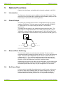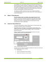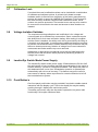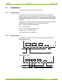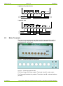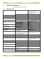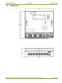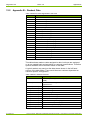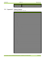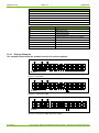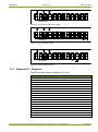
1
Electricity Meters
Residential BS / IEC
British Standard
5219 Polyphase, Multi-Rate
TOU Credit Meter
User Manual & Technical Specification
Date: 20/11/09
Filename: 5219 User Manual Version 4.0.doc
Q Pulse Number:IB048
© Landis+Gyr
Page 2 of 32
Issue: 4.0
Revision History
Revision History
Index
Date
Comments
4
18.11.2008
Revised manual to new branding guidelines and layout
Copyright notice
The material in this document is the property of Landis+Gyr. Our products are under continual
improvement and we reserve the right to make changes without prior notice.
Landis+Gyr
1 Lysander Drive,
Northfields Industrial Estate,
Market Deeping,
Peterborough
PE6 8FB
www.landisgyr.com
© Landis+Gyr
5219 Polyphase, Multi-Rate Credit Meter Externally Switched – User Manual & Technical Specification
Table of Contents
Issue: 4.0
Page 3 of 32
Table of Contents
1
Introduction____________________________________________________________ 5
1.1
Purpose _________________________________________________________________ 5
1.2
Meter Overview ___________________________________________________________ 5
1.3
Reference Standards _______________________________________________________ 5
2
Safety _________________________________________________________________ 6
2.1
Safety Information ________________________________________________________ 6
2.2
Responsibilities ___________________________________________________________ 6
2.3
Safety Regulations _________________________________________________________ 7
3
Operational Functions ___________________________________________________ 8
3.1
Measurement _____________________________________________________________ 8
3.2
Registers ________________________________________________________________ 8
3.3
Reverse / Export Energy Registration __________________________________________ 8
3.3.1
Reverse Energy Detection ___________________________________________________ 8
3.3.2
Import Energy Registration __________________________________________________ 9
3.3.3
Export Energy Registration __________________________________________________ 9
3.3.4
Unidirectional Registration __________________________________________________ 9
3.4
Reactive Energy ___________________________________________________________ 9
3.5
Maximum Demand_________________________________________________________ 9
3.5.1
Rolling Maximum Demand__________________________________________________ 10
3.5.2
Slab Maximum Demand____________________________________________________ 10
3.5.3
Quality of Supply _________________________________________________________ 11
3.6
Phase Indication _________________________________________________________ 11
3.7
Factory / Meter Serial Number ______________________________________________ 11
3.8
Meter Memory ___________________________________________________________ 11
3.9
Anti-creep ______________________________________________________________ 11
3.10
Temperature Range_______________________________________________________ 11
3.11
Power Supply ____________________________________________________________ 12
3.12
Influence of Supply Voltage ________________________________________________ 12
4
Core User Interfaces ___________________________________________________ 13
4.1
Display _________________________________________________________________ 13
4.2
Energy Registration _______________________________________________________ 13
4.3
Optical Interface _________________________________________________________ 13
5
Optional Functions _____________________________________________________ 14
5.1
Introduction _____________________________________________________________ 14
5.2
Pulsed Output ___________________________________________________________ 14
5.3
External Rate Switching ___________________________________________________ 14
5219 Polyphase, Multi-Rate Credit Meter Externally Switched- User Manual & Technical Specification
© Landis+Gyr
Page 4 of 32
Issue: 4.0
Table of Contents
5.4
No-Power Read _________________________________________________________ 14
5.5
Mode-C Data Readout ____________________________________________________ 15
5.6
Inductive Serial Data Port _________________________________________________ 15
5.7
Calibration Lock _________________________________________________________ 16
5.8
Voltage Isolation Switches _________________________________________________ 16
5.9
Landis+Gyr Switch Mode Power Supply ______________________________________ 16
5.10
Push Button’s ___________________________________________________________ 16
6
Installation ____________________________________________________________ 17
6.1
Construction ____________________________________________________________ 17
6.2
Connections ____________________________________________________________ 17
6.3
Meter Terminals _________________________________________________________ 18
6.4
Sealing Arrangement _____________________________________________________ 19
7
Technical Summary ____________________________________________________ 20
7.1
Technical Facts __________________________________________________________ 20
7.2
Dimensions _____________________________________________________________ 21
8
Maintenance and Service ________________________________________________ 22
8.1
Meter Check ____________________________________________________________ 22
8.2
Meter Testing ___________________________________________________________ 22
8.3
Post Installation Configuration Changes ______________________________________ 22
9
Measures in the Event of Faults __________________________________________ 23
9.1
Operating Faults _________________________________________________________ 23
9.2
Disconnecting the Meter __________________________________________________ 23
9.3
Repairing the Meter ______________________________________________________ 23
10
Decommissioning and Disposal __________________________________________ 25
11
Glossary of Terms and Standards_________________________________________ 26
11.1
Acronyms ______________________________________________________________ 26
11.2
Measurement Units ______________________________________________________ 26
12
Appendices ___________________________________________________________ 27
12.1
Appendix A – Inductive Serial Data Port ______________________________________ 27
12.2
Appendix B – Readout Data ________________________________________________ 28
12.3
Appendix C – Display Options ______________________________________________ 29
12.3.1
Display Examples ________________________________________________________ 30
12.4
Appendix D – Registers ___________________________________________________ 31
© Landis+Gyr
5219 Polyphase, Multi-Rate Credit Meter Externally Switched – User Manual & Technical Specification
Introduction
1
Issue: 4.0
Page 5 of 32
Introduction
Introducing the 5219 Polyphase meter
1.1
Purpose
This manual covers the operation, installation instructions and technical
specifications of the 5219 Polyphase credit meter. The 5219 range includes
single rate, externally switched multirate, and single or multirate pulse
output variants.
1.2
Meter Overview
The meter is a whole current credit meter, capable of measuring Active
(kWh) (class 1.0) and Reactive energy (KVArh) (class 2.0).
The Meter has 3 measuring elements capable of being configured as
•
3 phase, 4 wire.
•
3 phase, 3 wire.
•
2 phases of 3 phase, 4 wire.
•
Single phase, 2 wire.
•
Single phase, 3 wire.
In some of the above configurations the meters is able to act as a true
multi- voltage measurement device, remaining class accurate between
120Vac and 240Vac. (Both limits +15% to –20%)
The meter has been given a 20 year certification life by OFGEM, the
regulator for the UK. This is based on a reliability of better than 97% over
20 years calculated using an OFGEM model.
An LCD display’s all of the meter’s data.
1.3
Reference Standards
1.
BS EN62053 – 21:2003 Static meters for active energy. (Classes 1 &
2)
2.
BS EN62052 – 11:2003 Alternating current static watt-hour meters
for active energy. (Classes 1 & 2)
3.
BS5685: 1979: Part 1 Specification class 0.5, 1.0 and 2.0 Single
phase and Polyphase, single rate and multi-rate watt-hour meters.
4.
IEC62056-21:2002 Data Exchange for Meter Reading, Tariff and
Load Control. Direct Local Exchange
5.
SI1566: 1998 The Meters (Certification) Regulations 1998;
6.
DIN 43 857
Part 2 1978 Principal dimensions for Polyphase Meters
Part 4 1974 Principal dimensions of the terminal cover for
Polyphase Meters
5219 Polyphase, Multi-Rate Credit Meter Externally Switched– User Manual & Technical Specification
© Landis+Gyr
Page 6 of 32
Issue: 4.0
2
Safety
2.1
Safety Information
Safety
Attention is drawn as follows in the individual chapters of this user manual
with classified word symbols and pictographs to the relevant danger level,
i.e. the severity and probability of any danger:
Definition of Danger
This symbol is used to indicate a possibly dangerous situation which could
result in severe physical injury or a fatality.
Definition of Warning
This symbol is used to indicate a possibly dangerous situation which could
result in minor physical injury or material damage.
Definition of Note
This symbol is used to indicate general details and other useful information.
In addition to the danger level, all safety information also describes the type
and source of the danger, it’s possible consequences and measures to
counteract the danger.
2.2
Responsibilities
The owner of the meter – normally the utility – is responsible that all
persons engaged on work with the meter:
•
Have read and understood the relevant sections of this user
manual.
•
Are sufficiently qualified for the work to be performed.
•
Strictly observe the safety regulations and the operating information
in the individual chapters.
In particular, the owner of the meter bears responsibility for the protection
of persons, prevention of material damage and the training of personnel
(Landis+Gyr. provides training courses for this purpose on specific
equipment; please contact the relevant agent if interested).
© Landis+Gyr
5219 Polyphase, Multi-Rate Credit Meter Externally Switched – User Manual & Technical Specification
Safety
2.3
Issue: 4.0
Page 7 of 32
Safety Regulations
The following safety regulations must be observed at all times:
•
This equipment does not contain a disconnection device. Means for
disconnection from the supply must be provided as part of the
building installation. Do not work on the equipment unless the
supply is disconnected. If disconnection is done by removal of fuses
or other cut-outs, the removed disconnection devices must be kept
secure from replacement while work is performed. If disconnection
is provided by a switch, the switch shall conform to the requirements
of IEC 947-1 and IEC 947-3 or equivalent.
•
This equipment does not contain an over current protection device.
Over current protection must be provided as part of the building
installation. Maximum over current device rating is 125 Amp at 415
Volts, conforming to the requirements of BS1361, or equivalent.
•
Only suitably trained and qualified personnel shall be allowed to
work on the equipment. Local safety standards shall be observed
and shall take precedence over these regulations in points of
conflict.
•
The meter must be held securely during installation. They can
cause injuries if dropped.
•
Any meter that has fallen must not be installed, even if no damage
is apparent, but must be returned for testing to the service and
repair department responsible (or the manufacturer). Internal
damage can result in functional disorders or short-circuits.
•
The meter must on no account be cleaned with running water or
with high-pressure devices. Water penetration can cause shortcircuits.
•
The meter terminal cover should be secured in place before any
load is applied.
•
To avoid overheating, the meter must be connected using
appropriate cable sizes.
o
Currents up to 60A a cable with minimum 16mm2 cross-section
area.
o
Currents up to 100A a cable with minimum 25mm2 crosssection area.
o
Currents up to 125A a cable with minimum 35mm2 crosssection area.
5219 Polyphase, Multi-Rate Credit Meter Externally Switched– User Manual & Technical Specification
© Landis+Gyr
Page 8 of 32
3
Issue: 4.0
Operational Functions
Operational Functions
The standard operational functions of the 5219
3.1
Measurement
The meter has been designed to work with a wide range of voltages,
current ranges, and frequency options. Please refer to the technical
specifications for details.
The meter measures and registers kWh to class 1.0 and KVArh to class
2.0. There is a meter constant LED mounted on the front panel of the meter
for testing purposes, pulsing at a rate of 1,000 pulses per kWh.
The meter may be configured to register Import and Export energy. See
section Reverse / Export Energy Registration.
An option is available to ‘enable’ kVArh registration so that meters can be
supplied either ‘Active’ only or ‘Active / Reactive’. See section Reactive
energy.
3.2
Registers
The meter energy registers have the range 000000.000 - 999999.999 kWh.
The registers are displayed to a maximum of 2 decimal places unless
programmed via the Flag Port (see User Interfaces) to 3 decimal places for
testing purposes only. A complete table of registers is shown in the
appendix.
3.3
Reverse / Export Energy Registration
The meter is able to recognise reverse energy and deal with it according to
the configuration requested by the customer. The options include reverse
energy detection ‘rEd’, import registration only, unidirectional registration
and export energy registration. This configuration is done in the factory.
3.3.1
Reverse Energy Detection
The customer may have the meter configured such that when reverse
energy is detected the reverse energy warning shown below is displayed.
This display will alternate between its normal display and the warning
message. This reverse energy power threshold may be set between 0.23
kW and 35 kW, and is calculated over a period of 10 seconds. This
threshold is factory configurable and applies irrespective of what forward
power may be present during the same period of time.
The warning message can only be reset by LANDIS+GYR software or the
use of a HHU using the optical communication port on the front of the
meter. When clearing down the reverse energy detected ‘rEd message’ and
reverse Wh registers, the capacitive kVArh registers will not be affected.
12
34
Figure 1 rEd Message
© Landis+Gyr
5219 Polyphase, Multi-Rate Credit Meter Externally Switched – User Manual & Technical Specification
Operational Functions
Issue: 4.0
Page 9 of 32
The reverse energy detection is available in the registry modes below.
3.3.2
Import Energy Registration
In this configuration only forward Watt hours consumed are noted and
added to the Total kWh register.
3.3.3
Export Energy Registration
The consumption of each phase is added into the reverse or forward
registers as appropriate.
For example:
Phase R 5A forward, Phase S 5A forward, Phase T 10A reverse will result
in both forward and reverse registers increasing at the same rate. It will not
result in zero power being registered.
The impulse LED may be configured to flash when any power is registered,
forward or reverse.
3.3.4
Unidirectional Registration
The output from each phase will be added directly to the forward registers
regardless of the direction of the power.
For the example given above the current consumption will be identified as
20A and the impulse LED will flash accordingly.
3.4
Reactive Energy
The 5219 can be configured in the factory to measure and register reactive
energy. The reactive energy consumed will be registered as inductive or
capacitive as appropriate. The Total Reactive energy register can be
configured to show the sum of inductive and capacitive reactive energy or
the difference between them.
The 'Total kVArh' display message will therefore show:
Total Inductive kVArh + Total Capacitive kVArh.
Or
Total Inductive kVArh - Total Capacitive kVArh.
3.5
Maximum Demand
Maximum demand may be configured to work in either rolling mode as
illustrated below or slab. The maximum demand value in either case may
be measured in one of the following, kW, kVAr, or kVA.
The MD register has a range 00.00 to 99.99.
The meter stores the most previous Total MD value in memory and it may
be displayed if required.
The meter will measure and display the current MD values assigned to the
appropriate rates in the multirate variant.
The MD may be reset via the optical port using Landis+Gyr Software or
HHU, or front fascia mounted and seal-able MD button.
5219 Polyphase, Multi-Rate Credit Meter Externally Switched– User Manual & Technical Specification
© Landis+Gyr
Page 10 of 32
Issue: 4.0
Operational Functions
The display for maximum demand is shown below. KW is for illustration
only and will display as kVAr, kVA etc as appropriate.
1
2
3
KW
Figure 2 MD Display
3.5.1
Rolling Maximum Demand
Maximum Demand is calculated on a fifteen minute rolling period. Every
minute the power usage of the last 15 minutes is calculated and multiplied
by four to give the equivalent demand for a one-hour period. If this value is
larger than the previous largest stored value, this value replaces it in the
Maximum Demand register.
Rolling Maximum Demand provides better accuracy than slab MD. As
illustrated below the highest demand value will be measured this way, as
the peak of demand will be captured by the rolling 15-minute period.
Figure 3 Rolling Maximum Demand
10.00
8.00
6.00
kW
4.00
2.00
0.00
1 2 3 4 5 6 7 8 9 101112131415161718192021222324252627282930
Minutes
On power up, the MD register will remain at zero until 15 minutes have
passed. Maximum demand values will not be calculated until the buffer
holds complete data for the preceding 15 minutes.
When an MD store occurs (using the MD reset button), MD will remain
zeroed until 15 minutes have passed and the buffer holds data for the 15
minutes since the last MD store.
3.5.2
Slab Maximum Demand
This maximum demand method works by calculating the maximum demand
over fixed customer specifiable periods of minutes. These periods must be
factors of 60 minutes. The first period commences on power up of the
meter and continues thereafter until power fail or MD reset.
© Landis+Gyr
5219 Polyphase, Multi-Rate Credit Meter Externally Switched – User Manual & Technical Specification
Operational Functions
Issue: 4.0
Page 11 of 32
On powerfail the rising MD value of the current MD period is integrated over
the MDP and stored. If this value is larger than the previous largest MD
value, on power up the new largest value will become the stored MD value.
On MD reset the current MD value is cleared down, and a new MDP
started. The value at reset is stored as the most previous MD total.
3.5.3
Quality of Supply
The meter may be customer specified to measure and display RMS voltage
and current.
3.6
•
The Instantaneous Voltage Register has a range 000 to 999 Vac
•
The Instantaneous Current Register has a range 000 to 999 Amps.
Phase Indication
The Display will indicate phase voltage present on each phase with the
display of the following symbols. Ø1, Ø2, Ø3.
The voltage that the symbol appears can be configured at the factory
between 0 and 240V.
Additionally the phase symbol can be configured to flash to indicate reverse
connection or reverse energy detection.
3.7
Factory / Meter Serial Number
There is the ability within the meter to store a 46-digit serial number. The
most significant 20 digits of which can be laser printed to the meters front
fascia.
3.8
Meter Memory
All the meters data is recorded in Ferroelectric Random Access Memory
(FRAM) under the control of the microprocessor. All the kWh and kVAr
registers are stored in the FRAM and will are updated periodically and on
power-fail. The FRAM is able to be re-written and is stable (no memory
losses) throughout the life of the meter.
3.9
Anti-creep
Below starting current, the meter will enter into an anti-creep mode. In this
state the meter registration LED is permanently lit and the registers do not
increment. The LED remains lit until the meter current is increased in either
the forward or reverse direction beyond the starting current. See the
technical specification section for details of Ib.
3.10
Temperature Range
Operating range:
10°C to 45°C
Limit range of operation:
25°C to 60°C
Storage range*:
25°C to 70°C
*Maximum period of 6 hours at the extremes of this temperature range.
5219 Polyphase, Multi-Rate Credit Meter Externally Switched– User Manual & Technical Specification
© Landis+Gyr
Page 12 of 32
Issue: 4.0
Operational Functions
This complies with IEC 62052-11.
3.11
Power Supply
The power supply for the meter electronics is derived from all 3 phases.
The meter will continue to operate in the event of a loss of any one or two
phases.
3.12
Rated Voltage: 220 / 380 Vac
240 / 415 Vac
Operating Voltage Range: +15% to
20%
Influence of Supply Voltage
The meter complies with IEC 62052-11: Section 7.1.2. and is tested by
NMI.
© Landis+Gyr
Current Range:
5 to125 Amps
Frequency:
50Hz
Power Burden:
Less than 2 watts
5219 Polyphase, Multi-Rate Credit Meter Externally Switched – User Manual & Technical Specification
Core User Interfaces
4
Issue: 4.0
Page 13 of 32
Core User Interfaces
The inputs and outputs of the 5219
4.1
Display
All the meters data is displayed on a LCD on which the size of each value
character has a height of 8mm and a width of 3.5mm giving an overall area
of 28mm² per character. The LCD has a minimum life expectancy of 20
years.
The meter LCD display is designed to have a high angle of readability.
The meter shows six significant digits with a customer configurable number
of decimal places, 0, 1 or 2.
The display cycle advance is factory configurable to be:
•
An auto cycling system that shows the active rate “flashing” and
scrolls through each of the displays according to a configurable time
from 1 to 10 seconds.
•
By using a cycle display button mounted on the meters face.
•
A combination of both modes. The meter will auto cycle, with the
button providing a means of moving to the next display immediately.
OBIS display legends are available on request. This is a factory
configurable option. See Appendix.
A detailed drawing of the LCD is shown below. Further display illustrations
are shown in the appendix, along with a table of all available displays.
1
KWh
2
kvarh
3
kVAh
1
vrms
2
Irms
3
RC
4
5
RI
Figure 4 LCD Format
4.2
Energy Registration
Separate kWh and kVArh indicator LED’s are present on the front aspect of
the meter. The pulse value is identified on the meters fascia, at 1000 pulses
per kWh/kVArh. The pulses can be used for checking the meter calibration.
4.3
Optical Interface
The meter includes a FLAG optical interface based upon IEC6205621:2002. This optical interface supports the IEC1107 mode-c readout
protocol. The baud rate for communication via the optical interface can be
set in the meter. See technical summary for details.
5219 Polyphase, Multi-Rate Credit Meter Externally Switched– User Manual & Technical Specification
© Landis+Gyr
Page 14 of 32
5
Issue: 4.0
Optional Functions
Optional Functions
Optional user interfaces and additional functionality available in the 5219.
5.1
Introduction
The features in this section are in addition to the basic 5219 model. These
options must be requested when obtaining meter availability and price from
Landis+Gyr at the outset of the ordering process.
5.2
Pulsed Output
The meter has a pulsed output function, configurable through the optical
interface (FLAG) port. The pulse output meets with regulation IEC6205331: 1998 Class B. The output ratings are shown in the technical
specification.
The meter has the option of one voltage free pulse output for kWh. The
pulse output is configurable between 1 to 1000 pulses per kWh, (where
1000/kWh = whole number) with pulse duration of 40 to 500 mS in 20 mS
steps. Output format is as shown below; using terminals A and B (figure 6).
kWh
+
_
Figure 5 Pulse Output Format
5.3
External Rate Switching
The multi-rate variants are externally rate switched. The active rate is
selected externally by applying a signal; neutral or live, to the rate switching
inputs. The active rate is dependant on the number of rates the meter is
configured for 1, 2, 3, or 4 and the switching protocol the customer has
specified. Signal is applied to 1 auxiliary terminal, an alternative auxiliary
terminal, or both simultaneously to achieve 4 switched rates.
Additionally the meter may be taken with a combination of pulse output and
external rate switching. In this circumstance 1 auxiliary terminal is used for
rate switching and the meter may only be configured as a 2-rate meter.
5.4
No-Power Read
A meter variant is available that addresses the need of some customers to
be able to make meter readings while the network voltage is off. A front
fascia mounted push button is fitted which when pressed and held for 3
seconds latches the internal power circuit on. This powers the display,
© Landis+Gyr
5219 Polyphase, Multi-Rate Credit Meter Externally Switched – User Manual & Technical Specification
Optional Functions
Issue: 4.0
Page 15 of 32
cycle display button, and optical readout port temporarily and allows a 45
second period to read the registers, via display and or FLAG port readout.
After approximately 45 seconds the meter powers off regardless of whether
the button is still depressed, and will remain powered off for a period of 45
minutes. This mechanism protects the meters internal power source from
being fully discharged by constant button pressing.
The displays available during this function are customer specifiable.
A secondary back-up power source other than the RTC back-up battery is
used for this purpose.
5.5
Mode-C Data Readout
IEC1107 readout mode C is available via the optical FLAG port. The
enabled functions of the meter such as Export kWh registers, kVArh
registers, and maximum demand registers are supported and available
within this data stream. The conventions for the data are shown in the
appendix. The speed of the data readout is the same as for FLAG
communications, that is, 9600 baud.
5.6
Inductive Serial Data Port
The meter incorporates an Inductive Serial Data Port that transmits data
wirelessly. See table of data in the appendix.
This allows meter functionality to be extended at a future date by the
addition of an easy to fit add-on module without restricting access to the
optical port for the purpose of meter reading. There is no need for a
physical connection.
Fitting of modules is limited to removing existing terminal cover and
replacing with a module, as illustrated below.
Figure 6 Additional Modules (Future)
The data output provides all information available from within the meter and
would support any module including:
•
Prepayment
•
Power Line Remote Communication
•
Radio and Telephone Communication.
5219 Polyphase, Multi-Rate Credit Meter Externally Switched– User Manual & Technical Specification
© Landis+Gyr
Page 16 of 32
5.7
Issue: 4.0
Optional Functions
Calibration Lock
If required the meter’s calibration values can be locked with a combination
of hardware and software options. A printed circuit board mounted
hardware switch is fitted and on completion of the factory manufacturing
process this switch is armed by LANDIS+GYR software. FLAG access to
the meter memory locations concerned with calibration values, serial
number etc are then prevented. The terminal cover and top cover need to
be removed for this switch to be reset and access to these locations reinstated.
5.8
Voltage Isolation Switches
The requirement during calibration and certification is for voltage and
current signals to be isolated from one another. Some customers require
this ability also for their own verification testing. After testing is complete
and the meter is installed, the ability to do this is prevented by the fitting of
a terminal cover and seals. In markets where additional steps are required
to prevent non-technical losses, isolation switches may be fitted to the pcb,
that once closed prevent any isolation of voltage from current unless the
meter seals are broken and the top cover removed.
Additionally or alternatively mechanical bungs may be fitted behind the
terminal cover that serves the same purpose of preventing isolation of
voltage from current.
5.9
Landis+Gyr Switch Mode Power Supply
The Landis+Gyr switch mode power supply if fitted allows the 5219 to fulfil
the requirement of some markets and local approval bodies for the meter to
function with any 1 phase or neutral disconnected. This allows the meter to,
with balanced loads, move from 3Phase4wire operation to 3phase3wire
automatically with no loss of accuracy. This feature may prove useful in
some areas of industry where a provision for neutral connection is left off
the local distribution system.
5.10
Push Button’s
One front panel push button may be provided if required to enable manual
interaction with the display cycle. That is the display list may be read by
scrolling through 1 display with each button press.
This same push button may also be used to operate the no power read
functionality if this option has been fitted.
© Landis+Gyr
5219 Polyphase, Multi-Rate Credit Meter Externally Switched – User Manual & Technical Specification
Installation
6
Issue: 4.0
Page 17 of 32
Installation
Construction, Mounting and wiring of the 5219
6.1
Construction
The meter case dimensions conform to the following two standards,
BS5685: 1979: Part 1 and DIN 43 857: 1978: Part 2.The terminal cover
governed by DIN 43 857: 1974: Part 4. For DIN meters the meter will be
supplied with a separate clip-in device to make the design meet the DIN
Standard.
The Meter has a double insulated case which meets the requirements of
BS5685 and is manufactured from the following materials:
Base - Flame Retardant Polycarbonate
Top – Polycarbonate
Window - UV Stabilised Polycarbonate
Terminal Cover – Polycarbonate
Dimensions follow in the appendix.
6.2
Connections
The Meter has 3 measuring elements capable of being configured as:
Single phase 2 wire
ELEMENT
ELEMENT
ELEMENT
A
B
C
N
L1
N
L1
SUPPLY
LOAD
Single phase 3 wire
M/E A
M/E B
M/E C
N
N
L1 A
L1 A
L1 B
SUPPLY
5219 Polyphase, Multi-Rate Credit Meter Externally Switched– User Manual & Technical Specification
LOAD
L1 B
© Landis+Gyr
Page 18 of 32
Issue: 4.0
Installation
2 phases of 3 phase 4 wire
M/E A
M/EB
M/E C
N
L(1,2,3)
N
L(1,2,3)
L(3,1,2)
LOAD
SUPPLY
L(3,1,2)
3 phase 4 wire
M/E A
M/E B
M/E C
N
L1
L2
L3
N
L1
SUPPLY
6.3
LOAD
L2
L3
Meter Terminals
The main current terminals and auxiliary terminals are manufactured from
solid brass to the dimensions and pitch outlined in BS5685: 1979: Part 1
and DIN 43 857: 1978: Part 2.
Figure 7 - Terminal Arrangement Photograph
Figure 8 - Terminal Arrangement Plan
For Pulse Output (P/O) only models: Terminals A and B - pulse output
For Externally Switched only models: Terminals A and B - external switches
(4 rates)
© Landis+Gyr
5219 Polyphase, Multi-Rate Credit Meter Externally Switched – User Manual & Technical Specification
Installation
Issue: 4.0
Page 19 of 32
For Externally Switched and P/O models: Terminals A and B – pulse
output, terminal D – external switch (2 rates).
6.4
Sealing Arrangement
The meter is sealed conventionally, using sealing wires and the appropriate
seal for the intended market. The meter can be sealed for life if the
customer requests this service.
5219 Polyphase, Multi-Rate Credit Meter Externally Switched– User Manual & Technical Specification
© Landis+Gyr
Page 20 of 32
7
Issue: 4.0
Technical Summary
Technical Summary
The technical specifications of the 5219
7.1
Technical Facts
System Voltage
Current (Base)
Current (Max)
Starting Current
Max measuring range
Measuring Accuracy
Burdens
Three element meters
Supply variation
Direct Connection Ib
Imax
(IEC)
(IEC)
Typically 15mA for a balanced load
IEC 62053-21
Voltage Circuit @ 230Vac
Current Circuit @ Ib
Current circuit @ Imax
Supply frequency
Temperature Range
Meter Constant
Pulse Output
Display
Quality
OFGEM approval number
Certificated life
Construction
Terminal Arrangement
Terminal Diameter
Weight
Dimensions (mm)
Optical interface
Baud rate options (baud)
IP Rating
© Landis+Gyr
Frequency variation
Limit operating range
Storage range
The output meets IEC 6205331:1998 Class B
LCD 7 segment, 12 segments,
Icons for kWh, kVArh, inductive &
capacitive reactive power, reverse
energy, Irms and Vrms.
Manufactured to:
(standard terminal cover)
(extended terminal cover)
(standard terminal cover)
(extended terminal cover)
FLAG protocol based on standard
given above.
Communications via optical
interface
With Short terminal cover
With Extended terminal cover
240Vac Phase to Neutral
230Vac Phase to Neutral
220Vac Phase to Neutral 120Vac
Phase to Neutral
+15% to -20%
5A, 10A, 15A, 20A
80A, 100A, 105A, 120A, 125A.
0.4% of Ib
20mA up to 125A
Class 1 Active (kWh)
Class 2 & 3 Reactive (kVArh)
<2W <10VA
<0.5VA
<1VA
50Hz, 60Hz
± 5%
-25°C to 60°C
-25°C to 70°C
1000 imp/kWh
Max voltage 24V d.c.
Max current 6mA
Character size – 8x3.5mm.
6 significant numbers, 2 decimal
places
ISO 9001:2000
981
20 Years
Flame Retardant
Polycarbonate, window UV
Stablised
BS5685
8.3mm
950g
1070g
H 175.8 x W 167.9 x D 56.3
H 245 x W 173 x D 58
300, 1200, 4800, 9600
IP51
IP54
5219 Polyphase, Multi-Rate Credit Meter Externally Switched – User Manual & Technical Specification
Technical Summary
7.2
Issue: 4.0
Page 21 of 32
Dimensions
Figure 9 - Dimensional Drawing of the 5219 Meter
5219 Polyphase, Multi-Rate Credit Meter Externally Switched– User Manual & Technical Specification
© Landis+Gyr
Page 22 of 32
Issue: 4.0
8
Maintenance and Service
8.1
Meter Check
Maintenance and Service
While it isn’t necessary, under normal circumstances, to perform any
maintenance on the installed meter, the following are check points that
should be observed during scheduled periodic meter visits.
8.2
•
Is the meter dry and clean, particularly the LCD display and the
optical interface?
•
Does the meter display a legible and sensible display? i.e. does the
meter appear in a serviceable condition.
•
Check all factory fitted and company fitted seals are in place secure
and intact.
•
Observe display for any error messages or notifications
•
Confirm that the energy registers have changed to a reasonable
degree since the last visit.
•
If irregularities are found, continue as in section 8.
Meter Testing
The testing of meters, either random sample or on all meters, should be
carried out periodically according to national regulations. The meter must
be removed as described in section 8.3 and replaced with a meter of similar
type for the duration of the tests.
8.3
Post Installation Configuration Changes
With the aid of a laptop computer or other suitable hand held device a flag
probe and Landis+Gyr specific software, it is possible to amend the factory
configured options of the meter. It is beyond the scope of this manual to
describe in any further detail the procedure. Landis+Gyr sales team would
be happy to discuss specific requirements.
© Landis+Gyr
5219 Polyphase, Multi-Rate Credit Meter Externally Switched – User Manual & Technical Specification
Measures in the Event of Faults
Issue: 4.0
9
Measures in the Event of Faults
9.1
Operating Faults
Page 23 of 32
If the LCD window is illegible or the data readout does not function, the
following points should be checked.
Is the mains voltage present? – Are the preliminary fuses intact?
Has the minimum or maximum recommended ambient temperature been
exceeded?
Is the LCD window clear of all debris? – Not misted over, painted over or
soiled in any way.
If none of the above are causing the fault the meter should be disconnected
as per section 9.2, replaced if required as detailed in section 6 and returned
to Landis+Gyr as described in section 9.3.
9.2
Disconnecting the Meter
Remove preliminary fuses before continuing
The connecting conductors should not be Live when removing the meter.
Electrically Live parts are a life threatening hazard. Preliminary fuses should
be removed and kept in a safe place until all work is complete, where they
cannot be replaced by anyone unnoticed.
Proceed as follows:
9.3
•
Remove the company seal on the terminal cover (if fitted).
•
Release the two terminal cover screws and remove terminal cover.
•
Check with a suitable voltage testing device that the phase
connections are not live. If they are live then remove the preliminary
fuses and keep in a safe place until all work is complete, where they
cannot be replaced by anyone unnoticed.
•
Remove the signal inputs and outputs by releasing the auxiliary
terminal screws.
•
Remove the phase connections by releasing the main terminal
screws.
•
If required fit a suitable replacement meter as described in section
6.
Repairing the Meter
There are no user serviceable parts inside the meter. Breaking factory
calibration seals will invalidate the calibration status of the meter. In the
event of a meter requiring repair, proceed as follows.
•
Remove the meter from the installation as detailed in section 9.2.
•
Attach a label, which describes the fault as accurately as possible,
to the meter and include name and contact details of person
responsible in case of inquiries.
5219 Polyphase, Multi-Rate Credit Meter Externally Switched– User Manual & Technical Specification
© Landis+Gyr
Page 24 of 32
© Landis+Gyr
Issue: 4.0
Measures in the Event of Faults
•
Package the meter to ensure no further damage can occur during
transit.
•
Send the meter back to Landis+Gyr.
5219 Polyphase, Multi-Rate Credit Meter Externally Switched – User Manual & Technical Specification
Decommissioning and Disposal
10
Issue: 4.0
Page 25 of 32
Decommissioning and Disposal
The procedure for the safe removal of the meter from the installation is
described in section 9.3. Please ensure that ALL SAFETY PRECAUTIONS
are met before proceeding.
Based on the environmental certificate ISO 14001, the components used to
manufacture the meter can, in the main, be broken down into constituent
parts and sent for suitable recycling or disposal.
The following are general guidelines and should NOT take priority over local
disposal and environmental policies which should be adhered to without
compromise.
Component Parts
Printed Circuit Boards
LCD Display
Metal Components
Plastic Components
Disposal
Treated as per disposal of Electronic Equipment
Sorted and delivered to collective recycling point
Sorted and delivered for re-granulation if at all
possible
5219 Polyphase, Multi-Rate Credit Meter Externally Switched– User Manual & Technical Specification
© Landis+Gyr
Page 26 of 32
Issue: 4.0
11
Glossary of Terms and Standards
11.1
Acronyms
Acronym
BS
DFS
DIN
ECD
EEPROM
IEC
ISO
LCD
LED
MD
MID
NPR
OFGEM
PTR
RED
11.2
Glossary of Terms and Standards
Definition
British Standard
Direct Field Sensor
Deutsches Institut für Normung (German Institute For
Standardisation)
External Connection Diagram
Electrically Erasable Programmable Read Only Memory (E2)
International Electrotechnical Commission
International Standards Organisation
Liquid Crystal Display
Light Emitting Diode
Maximum Demand
Metering Industry Directive
No Power Read
The Office of Gas and Electricity Markets
Photo-transistor
Reverse Energy Detected
Measurement Units
A
Hz
Iref
Kg
kVAh
kvarh
kWh
mm
mO
ms
Nm
o
C
UN
UT
V
© Landis+Gyr
Ampere (unit of current)
Hertz (unit of frequency)
MID reference current
Kilogramme (unit of weight)
Kilo Volt Ampere hour
kilo Volt Amps reactive hour
kilo Watt-hour
millimetre (unit of distance)
milliohm (unit of resistance)
millisecond
Newton meter (unit of torque)
Degree Celsius (unit of temperature)
Rated supply voltage of meter
Rated external switch voltage
Volt
5219 Polyphase, Multi-Rate Credit Meter Externally Switched – User Manual & Technical Specification
Appendices
12
Issue: 4.0
Page 27 of 32
Appendices
Additional information for the 5219
12.1
Appendix A – Inductive Serial Data Port
The inductive signal is a 26 KHz square wave modulated by the data
transmitted at 1200 baud. The stream of bytes representing the data is
repeated at 6-second intervals. The table below shows the data available in
the transmission.
Table 1 Inductive Loop Data Stream
Block Description
STX character
Meter type and hardware version
Serial number
R1 Import kWh Register (or Total
kWh in a single rate meter)
R2 Import kWh Register
R3 Import kWh Register
R4 Import kWh Register
R1 Export kWh Register (or Total
Export kWh in a single rate meter)
R2 Export kWh Register
R3 Export kWh Register
R4 Export kWh Register
R1 Inductive kVArh Register
R2 Inductive kVArh Register
R3 Inductive kVArh Register
R4 Inductive kVArh Register
R1 Capacitive kVArh Register
R2 Capacitive kVArh Register
R3 Capacitive kVArh Register
R4 Capacitive kVArh Register
Active Rate
Customer ID
ETX character
BCC character
Block Byte
Count
1
8
20
8
Start of transmission
I.e. AMP5219A
Most significant 20 digits
In Wh
8
8
8
8
In Wh
In Wh
In Wh
In Wh
8
8
8
8
8
8
8
8
8
8
8
2
2
1
1
In Wh
In Wh
In Wh
In Wh
In Wh
In Wh
In Wh
In Wh
In Wh
In Wh
In Wh
Identification of
Configuration file number
End of transmission
Block check character
5219 Polyphase, Multi-Rate Credit Meter Externally Switched– User Manual & Technical Specification
Comment
© Landis+Gyr
Page 28 of 32
12.2
Issue: 4.0
Appendices
Appendix B – Readout Data
Table 2 Readout Codes Applicable to the 5219
Code
0.00.6
2.18.1
2.18.2
2.18.3
2.18.4
2.18.0
3.28.1
3.28.2
3.28.3
3.28.4
3.28.0
2.58.1
2.58.2
2.58.3
2.58.4
2.58.0
2.16.1
2.16.2
2.16.3
2.16.4
2.16.0
Definition
Serial number
Rate 1 kWh register
Rate 2 kWh register
Rate 3 kWh register
Rate 4 kWh register
Total kWh register
Rate 1 Export kWh register
Rate 2 Export kWh register
Rate 3 Export kWh register
Rate 4 Export kWh register
Total Export kWh register
Rate 1 Inductive (+kVArh) register
Rate 2 Inductive (+kVArh) register
Rate 3 Inductive (+kVArh) register
Rate 4 Inductive (+kVArh) register
Total Inductive (+kVArh) register
Rate 1 MD value, rolling or slab
Rate 2 MD value, rolling or slab
Rate 3 MD value, rolling or slab
Rate 4 MD value, rolling or slab
Total MD value, rolling or slab
This table shows readout codes assigned to date, but these are assigned
on an as needed basis and according to customer specifications. Therefore
options available are not limited to those in this table.
A typical readout may send out the data stream shown in the left hand
column of the table below. There would be some variance dependant on
customer specific configuration.
Table 3 Mode-C Readout Formats
Data Stream
/AMP55219-0502
0.00.6.0(SAMPLE31)
0.00.6.1(0374132)
2.18.1(000000.00)*
2.18.2(000000.00)
2.18.0(000000.00)
3.28.1(000000.00)
3.28.2(000000.00)
3.28.0(000000.00)
2.58.1(000000.00)
2.58.2(000000.00)
2.58.0(000000.00)
2.16.1(00.00)
© Landis+Gyr
Explanatory Notes
Baud rate (5=9600), hardware (5219) and software issue
(0502)
Serial number, 16 digits across 2 lines as shown or 9
digits across 1.
Rate 1 kWh register
Rate 2 kWh register
Total kWh register
Rate 1 Export kWh register
Rate 2 Export kWh register
Total Export kWh register
Rate 1 Inductive (+kVArh) register
Rate 2 Inductive (+kVArh) register
Total Inductive (+kVArh) register a
Rate 1 MD value
5219 Polyphase, Multi-Rate Credit Meter Externally Switched – User Manual & Technical Specification
Appendices
Issue: 4.0
Data Stream
2.16.2(00.00)
2.16.0(00.00)!8
Page 29 of 32
Explanatory Notes
Rate 2 MD value
Total MD value and sign off checksum
*N.B All registers (000000.00) are shown here with no kWh/kVArh values.
12.3
Appendix C – Display Options
Table4 Available Displays in the 5219
Description of available displays
Software Version
Hardware variant / software options
Display Test
Total Import kWh
Rate 1 Import kWh
Rate 2 Import kWh
Rate 3 Import kWh
Rate 4 Import kWh
Active Rate Import kWh
Total Export kWh
Rate 1 Export kWh
Rate 2 Export kWh
Rate 3 Export kWh
Rate 4 Export kWh
Active Rate Export kWh
Total Sum/Difference kVArh
Rate 1 Sum/Difference kVArh
Rate 2 Sum/Difference kVArh
Rate 3 Sum/Difference kVArh
Rate 4 Sum/Difference kVArh
Active Rate Sum./Difference kVArh
Total Inductive kVArh
Rate 1 Inductive kVArh
Rate 2 Inductive kVArh
Rate 3 Inductive kVArh
Rate 4 Inductive kVArh
Active Rate Inductive kVArh
Total Capacitive kVArh
Rate 1 Capacitive kVArh
Rate 2 Capacitive kVArh
Rate 3 Capacitive kVArh
Rate 4 Capacitive kVArh
Active Rate Capacitive kVArh
Total Maximum Demand
R1 Maximum Demand
R2 Maximum Demand
R3 Maximum Demand
R4 Maximum Demand
Previous Total Maximum Demand
Cumulative Maximum Demand
Maximum Demand Reset Count
5219 Polyphase, Multi-Rate Credit Meter Externally Switched– User Manual & Technical Specification
© Landis+Gyr
Page 30 of 32
Issue: 4.0
Appendices
Description of available displays
Phase 1 Vrms
Phase 2 Vrms
Phase 3 Vrms
Phase 1 Irms
Phase 2 Irms
Phase 3 Irms
Table 5 Alternative OBIS Displays
Obis Code
01
20
21
22
23
81
82
83
84
Register
MD reset count
Total Import kWh
Total Export kWh
Total Inductive (or sum of L+C) kVArh
Total Capacitive kVArh
R1 Import kWh
R2 Import kWh
R3 Import kWh
R4 Import kWh
12.3.1 Display Examples
The examples below show the symbols used for the various registers.
1
2
3
KWh
Figure 10 Total kWh
1
2
3
KWh
Figure 11 Total Export kWh
1
2
3
KWh
Figure 12 Total Export kWh alternative display
© Landis+Gyr
5219 Polyphase, Multi-Rate Credit Meter Externally Switched – User Manual & Technical Specification
Appendices
Issue: 4.0
1
2
Page 31 of 32
3
KVArh
Figure 13 Total Sum or Difference kVArh
1
2
3
KVArh
RI
Figure 14 Total Inductive kVArh
1
2
3
KVArh
RC
Figure 15 Total Capacitive kVArh
12.4
Appendix D – Registers
Table 6 Potential Registers available in the 5219
Potential Registers
Total Import kWh
Rate 1 Import kWh*
Rate 2 Import kWh
Rate 3 Import kWh
Rate 4 Import kWh
Total Export kWh
Rate 1 Export kWh
Rate 2 Export kWh
Rate 3 Export kWh
Rate 4 Export kWh
Total Sum/Difference kVArh
Rate 1 Sum/Difference kVArh
Rate 2 Sum/Difference kVArh
Rate 3 Sum/Difference kVArh
Rate 4 Sum/Difference kVArh
Total Inductive kVArh
Rate 1 Inductive kVArh
Rate 2 Inductive kVArh
5219 Polyphase, Multi-Rate Credit Meter Externally Switched– User Manual & Technical Specification
© Landis+Gyr
Page 32 of 32
Issue: 4.0
Appendices
Potential Registers
Rate 3 Inductive kVArh
Rate 4 Inductive kVArh
Total Capacitive kVArh
Rate 1 Capacitive kVArh
Rate 2 Capacitive kVArh
Rate 3 Capacitive kVArh
Rate 4 Capacitive kVArh
Total Maximum Demand
R1 Maximum Demand
R2 Maximum Demand
R3 Maximum Demand
R4 Maximum Demand
Previous Total Maximum Demand
Cumulative Maximum Demand
*N.B Actual register combinations depends upon meter variant used
Top of the Document
© Landis+Gyr
5219 Polyphase, Multi-Rate Credit Meter Externally Switched – User Manual & Technical Specification